EP3687196B1 - First responder tracking breadcrumbs - Google Patents
First responder tracking breadcrumbs Download PDFInfo
- Publication number
- EP3687196B1 EP3687196B1 EP20164449.9A EP20164449A EP3687196B1 EP 3687196 B1 EP3687196 B1 EP 3687196B1 EP 20164449 A EP20164449 A EP 20164449A EP 3687196 B1 EP3687196 B1 EP 3687196B1
- Authority
- EP
- European Patent Office
- Prior art keywords
- beacon
- portable
- emergency responder
- portable device
- location
- Prior art date
- Legal status (The legal status is an assumption and is not a legal conclusion. Google has not performed a legal analysis and makes no representation as to the accuracy of the status listed.)
- Active
Links
- 235000012813 breadcrumbs Nutrition 0.000 title description 2
- 238000000034 method Methods 0.000 claims description 15
- 238000004891 communication Methods 0.000 claims description 11
- 230000003213 activating effect Effects 0.000 claims description 3
- 239000000853 adhesive Substances 0.000 claims description 3
- 230000001070 adhesive effect Effects 0.000 claims description 3
- 230000029058 respiratory gaseous exchange Effects 0.000 claims description 2
- 238000001514 detection method Methods 0.000 description 3
- 230000007246 mechanism Effects 0.000 description 2
- 238000012986 modification Methods 0.000 description 2
- 230000004048 modification Effects 0.000 description 2
- 238000012544 monitoring process Methods 0.000 description 2
- 230000008569 process Effects 0.000 description 2
- 238000012545 processing Methods 0.000 description 2
- 239000011435 rock Substances 0.000 description 2
- 230000000007 visual effect Effects 0.000 description 2
- 230000004913 activation Effects 0.000 description 1
- 230000004075 alteration Effects 0.000 description 1
- 230000005540 biological transmission Effects 0.000 description 1
- 239000004566 building material Substances 0.000 description 1
- 230000010267 cellular communication Effects 0.000 description 1
- 238000012790 confirmation Methods 0.000 description 1
- 238000004519 manufacturing process Methods 0.000 description 1
- 239000003550 marker Substances 0.000 description 1
- 230000000135 prohibitive effect Effects 0.000 description 1
- 238000011084 recovery Methods 0.000 description 1
- 238000006467 substitution reaction Methods 0.000 description 1
Images


Classifications
-
- H—ELECTRICITY
- H04—ELECTRIC COMMUNICATION TECHNIQUE
- H04W—WIRELESS COMMUNICATION NETWORKS
- H04W4/00—Services specially adapted for wireless communication networks; Facilities therefor
- H04W4/02—Services making use of location information
- H04W4/029—Location-based management or tracking services
-
- A—HUMAN NECESSITIES
- A62—LIFE-SAVING; FIRE-FIGHTING
- A62C—FIRE-FIGHTING
- A62C99/00—Subject matter not provided for in other groups of this subclass
- A62C99/009—Methods or equipment not provided for in groups A62C99/0009 - A62C99/0081
-
- G—PHYSICS
- G01—MEASURING; TESTING
- G01C—MEASURING DISTANCES, LEVELS OR BEARINGS; SURVEYING; NAVIGATION; GYROSCOPIC INSTRUMENTS; PHOTOGRAMMETRY OR VIDEOGRAMMETRY
- G01C21/00—Navigation; Navigational instruments not provided for in groups G01C1/00 - G01C19/00
- G01C21/20—Instruments for performing navigational calculations
- G01C21/206—Instruments for performing navigational calculations specially adapted for indoor navigation
-
- G—PHYSICS
- G01—MEASURING; TESTING
- G01S—RADIO DIRECTION-FINDING; RADIO NAVIGATION; DETERMINING DISTANCE OR VELOCITY BY USE OF RADIO WAVES; LOCATING OR PRESENCE-DETECTING BY USE OF THE REFLECTION OR RERADIATION OF RADIO WAVES; ANALOGOUS ARRANGEMENTS USING OTHER WAVES
- G01S1/00—Beacons or beacon systems transmitting signals having a characteristic or characteristics capable of being detected by non-directional receivers and defining directions, positions, or position lines fixed relatively to the beacon transmitters; Receivers co-operating therewith
-
- G—PHYSICS
- G01—MEASURING; TESTING
- G01S—RADIO DIRECTION-FINDING; RADIO NAVIGATION; DETERMINING DISTANCE OR VELOCITY BY USE OF RADIO WAVES; LOCATING OR PRESENCE-DETECTING BY USE OF THE REFLECTION OR RERADIATION OF RADIO WAVES; ANALOGOUS ARRANGEMENTS USING OTHER WAVES
- G01S5/00—Position-fixing by co-ordinating two or more direction or position line determinations; Position-fixing by co-ordinating two or more distance determinations
- G01S5/02—Position-fixing by co-ordinating two or more direction or position line determinations; Position-fixing by co-ordinating two or more distance determinations using radio waves
- G01S5/0205—Details
- G01S5/0226—Transmitters
- G01S5/0231—Emergency, distress or locator beacons
-
- G—PHYSICS
- G06—COMPUTING; CALCULATING OR COUNTING
- G06Q—INFORMATION AND COMMUNICATION TECHNOLOGY [ICT] SPECIALLY ADAPTED FOR ADMINISTRATIVE, COMMERCIAL, FINANCIAL, MANAGERIAL OR SUPERVISORY PURPOSES; SYSTEMS OR METHODS SPECIALLY ADAPTED FOR ADMINISTRATIVE, COMMERCIAL, FINANCIAL, MANAGERIAL OR SUPERVISORY PURPOSES, NOT OTHERWISE PROVIDED FOR
- G06Q10/00—Administration; Management
- G06Q10/08—Logistics, e.g. warehousing, loading or distribution; Inventory or stock management
- G06Q10/083—Shipping
- G06Q10/0833—Tracking
-
- G—PHYSICS
- G06—COMPUTING; CALCULATING OR COUNTING
- G06Q—INFORMATION AND COMMUNICATION TECHNOLOGY [ICT] SPECIALLY ADAPTED FOR ADMINISTRATIVE, COMMERCIAL, FINANCIAL, MANAGERIAL OR SUPERVISORY PURPOSES; SYSTEMS OR METHODS SPECIALLY ADAPTED FOR ADMINISTRATIVE, COMMERCIAL, FINANCIAL, MANAGERIAL OR SUPERVISORY PURPOSES, NOT OTHERWISE PROVIDED FOR
- G06Q50/00—Systems or methods specially adapted for specific business sectors, e.g. utilities or tourism
- G06Q50/10—Services
-
- G—PHYSICS
- G08—SIGNALLING
- G08B—SIGNALLING OR CALLING SYSTEMS; ORDER TELEGRAPHS; ALARM SYSTEMS
- G08B21/00—Alarms responsive to a single specified undesired or abnormal condition and not otherwise provided for
- G08B21/02—Alarms for ensuring the safety of persons
- G08B21/0202—Child monitoring systems using a transmitter-receiver system carried by the parent and the child
- G08B21/0241—Data exchange details, e.g. data protocol
- G08B21/0247—System arrangements wherein the alarm criteria uses signal strength
-
- G—PHYSICS
- G08—SIGNALLING
- G08B—SIGNALLING OR CALLING SYSTEMS; ORDER TELEGRAPHS; ALARM SYSTEMS
- G08B21/00—Alarms responsive to a single specified undesired or abnormal condition and not otherwise provided for
- G08B21/02—Alarms for ensuring the safety of persons
- G08B21/0202—Child monitoring systems using a transmitter-receiver system carried by the parent and the child
- G08B21/0272—System arrangements wherein the object is to detect exact location of child or item using triangulation other than GPS
-
- G—PHYSICS
- G08—SIGNALLING
- G08B—SIGNALLING OR CALLING SYSTEMS; ORDER TELEGRAPHS; ALARM SYSTEMS
- G08B21/00—Alarms responsive to a single specified undesired or abnormal condition and not otherwise provided for
- G08B21/02—Alarms for ensuring the safety of persons
- G08B21/0202—Child monitoring systems using a transmitter-receiver system carried by the parent and the child
- G08B21/0277—Communication between units on a local network, e.g. Bluetooth, piconet, zigbee, Wireless Personal Area Networks [WPAN]
-
- G—PHYSICS
- G08—SIGNALLING
- G08B—SIGNALLING OR CALLING SYSTEMS; ORDER TELEGRAPHS; ALARM SYSTEMS
- G08B21/00—Alarms responsive to a single specified undesired or abnormal condition and not otherwise provided for
- G08B21/02—Alarms for ensuring the safety of persons
- G08B21/0202—Child monitoring systems using a transmitter-receiver system carried by the parent and the child
- G08B21/0294—Display details on parent unit
-
- G—PHYSICS
- G08—SIGNALLING
- G08B—SIGNALLING OR CALLING SYSTEMS; ORDER TELEGRAPHS; ALARM SYSTEMS
- G08B25/00—Alarm systems in which the location of the alarm condition is signalled to a central station, e.g. fire or police telegraphic systems
- G08B25/009—Signalling of the alarm condition to a substation whose identity is signalled to a central station, e.g. relaying alarm signals in order to extend communication range
-
- G—PHYSICS
- G08—SIGNALLING
- G08B—SIGNALLING OR CALLING SYSTEMS; ORDER TELEGRAPHS; ALARM SYSTEMS
- G08B25/00—Alarm systems in which the location of the alarm condition is signalled to a central station, e.g. fire or police telegraphic systems
- G08B25/01—Alarm systems in which the location of the alarm condition is signalled to a central station, e.g. fire or police telegraphic systems characterised by the transmission medium
- G08B25/016—Personal emergency signalling and security systems
-
- G—PHYSICS
- G08—SIGNALLING
- G08B—SIGNALLING OR CALLING SYSTEMS; ORDER TELEGRAPHS; ALARM SYSTEMS
- G08B7/00—Signalling systems according to more than one of groups G08B3/00 - G08B6/00; Personal calling systems according to more than one of groups G08B3/00 - G08B6/00
- G08B7/06—Signalling systems according to more than one of groups G08B3/00 - G08B6/00; Personal calling systems according to more than one of groups G08B3/00 - G08B6/00 using electric transmission, e.g. involving audible and visible signalling through the use of sound and light sources
- G08B7/066—Signalling systems according to more than one of groups G08B3/00 - G08B6/00; Personal calling systems according to more than one of groups G08B3/00 - G08B6/00 using electric transmission, e.g. involving audible and visible signalling through the use of sound and light sources guiding along a path, e.g. evacuation path lighting strip
-
- H—ELECTRICITY
- H04—ELECTRIC COMMUNICATION TECHNIQUE
- H04W—WIRELESS COMMUNICATION NETWORKS
- H04W4/00—Services specially adapted for wireless communication networks; Facilities therefor
- H04W4/30—Services specially adapted for particular environments, situations or purposes
- H04W4/33—Services specially adapted for particular environments, situations or purposes for indoor environments, e.g. buildings
-
- H—ELECTRICITY
- H04—ELECTRIC COMMUNICATION TECHNIQUE
- H04W—WIRELESS COMMUNICATION NETWORKS
- H04W4/00—Services specially adapted for wireless communication networks; Facilities therefor
- H04W4/80—Services using short range communication, e.g. near-field communication [NFC], radio-frequency identification [RFID] or low energy communication
-
- H—ELECTRICITY
- H04—ELECTRIC COMMUNICATION TECHNIQUE
- H04W—WIRELESS COMMUNICATION NETWORKS
- H04W4/00—Services specially adapted for wireless communication networks; Facilities therefor
- H04W4/90—Services for handling of emergency or hazardous situations, e.g. earthquake and tsunami warning systems [ETWS]
-
- H—ELECTRICITY
- H04—ELECTRIC COMMUNICATION TECHNIQUE
- H04W—WIRELESS COMMUNICATION NETWORKS
- H04W88/00—Devices specially adapted for wireless communication networks, e.g. terminals, base stations or access point devices
- H04W88/02—Terminal devices
- H04W88/04—Terminal devices adapted for relaying to or from another terminal or user
-
- H—ELECTRICITY
- H04—ELECTRIC COMMUNICATION TECHNIQUE
- H04B—TRANSMISSION
- H04B1/00—Details of transmission systems, not covered by a single one of groups H04B3/00 - H04B13/00; Details of transmission systems not characterised by the medium used for transmission
- H04B1/38—Transceivers, i.e. devices in which transmitter and receiver form a structural unit and in which at least one part is used for functions of transmitting and receiving
Definitions
- the location of people and objects inside an environment may be important.
- the cost of acquiring location data should not be prohibitive.
- Systems that can send and receive signals, and then process the signals to provide a location can be expensive. Reducing the cost of such systems is desirable.
- US 7,598,856 B1 discloses a navigation system for navigating in low visibility environments, including a portable detection unit which uses position and orientation sensors and/or wireless location to track the position of the portable detection unit relative to some reference location, such as a fire truck. The relative position of the portable detection unit, and thus its user, is then output to a visual display for viewing by the user so that the user may see his/her position in a dark or smoky environment.
- the system may also include portable beacons which may be left at landmarks so that the relative positions of the landmarks may be seen on the visual display.
- component or feature may,” “can,” “could,” “should,” “would,” “preferably,” “possibly,” “typically,” “optionally,” “for example,” “often,” or “might” (or other such language) be included or have a characteristic, that particular component or feature is not required to be included or to have the characteristic. Such component or feature may be optionally included, or it may be excluded.
- Locating firefighters and emergency workers on the grounds of an active incident has been a key unmet need for some time. Precise location and tracking has been demonstrated to be feasible, but is currently orders of magnitude beyond acceptable cost targets. While some systems such as a Global Positioning System (GPS) could be used, such systems may not work within a closed structure. In addition, such systems often consume large amounts of power from the devices carried by the firefighters and emergency works. Most frequently, incident commanders may need to know the vicinity (e.g., side of the building, floor of the building) of a team member, rather than an exact position.
- GPS Global Positioning System
- Firefighter or emergency workers may cany portable systems (e.g., a self-contained breathing apparatus ("SCBA")) that can include a low cost, low power radio frequency (“RF”) transceiver.
- SCBA self-contained breathing apparatus
- RF radio frequency
- These simple, disposable, low cost RF beacons may be provided to key members of a firefighting team, as they enter and move around a structure. At key points inside or outside the structure, the firefighters may take one of the RF beacons, activate the RF beacon (e.g., by turning dial 104, etc.), and mount it to a surrounding structure.
- the RF beacon may begin transmitting a signal (e.g., wireless) providing its identification and/or location.
- the RF beacon may have a simple mounting mechanism (e.g., screws, bolts, straps, adhesive, or combinations thereof) to allow mounting of the RF beacon on many internal or external structures, such as, for example, a wall, door, siding, tree, telephone pole, etc.
- a firefighter activates and attaches the RF beacon to a surrounding structure, the firefighter may also contact the incident commander and indicate the location of the RF beacon and verify its correct operation.
- the incident commander may maintain a map containing the locations of all of the RF beacons deployed, or list the location of each of the RF beacons using software integrated to an incident commander (e.g., a computer). Since the signal for the RF beacon may not travel significant distances; when subsequent firefighters pass through the same vicinity, their portable systems may detect the RF beacon and may relay the identification of the RF beacon back to the incident commander. Since the RF signal may travel a short distance, the incident commander can precisely note the place and time the firefighter was at that location associated with the specific RF beacon. Additional uses of the RF beacons may include mounting the RF beacons on rocks or heavy objects that can be thrown into a structure. If the RF beacon is thrown into the vicinity of a lost firefighter, the relay of the RF beacon identification can be used to confirm the firefighter's position.
- an incident commander e.g., a computer
- FIG. 1 is a schematic illustration of an RF beacon 100.
- the RF beacon 100 includes an RF module 102 configured to communicate via radio frequencies.
- the RF beacon 100 may also include dial 104 for turning the RF beacon 100 on/off Dial 104 may also be utilized to set an address (e.g., a unique address) of the location of the RF beacon 100.
- Dial 104 may set the address via a color coding scheme (e.g., a specific color for a specific location, set by the factory/manufacturing facility or automatically set by a firefighter's system/equipment).
- a color coding scheme e.g., a specific color for a specific location, set by the factory/manufacturing facility or automatically set by a firefighter's system/equipment.
- the RF beacon 100 may have a length, L, from about 1.5 inches to about 3 inches; a width, W, from about 1 inch to about 2 inches; and a height, H, from about 0.5 inch to about 1 inch.
- the RF beacon 100 may be of any suitable shape, such as, for example, a polyhedron (e.g., cube, rectangular prism, a triangular prism).
- the RF beacon 100 may operate using a battery having a suitable voltage (e.g., a 3 volt battery, etc.) and may be waterproof and/or heat resistant up to about 600°F.
- the RF beacon 100 may be constructed in a minimally insulated package allowing it to survive for a short time period in a fire situation in order to transmit signals that can be relayed (e.g., through a portable device, etc.) back to an incident commander (e.g., incident commander 112 shown on FIG. 2 ).
- incident commander e.g., incident commander 112 shown on FIG. 2 .
- the RF beacon 100 may be a low power radio/battery combination that uses one of many wireless protocols, such as, for example, low power protocols such as Bluetooth Low Energy ("BLE”), low power wide area network (“LPWAN”), 802.15.4, or combinations thereof.
- BLE Bluetooth Low Energy
- LPWAN low power wide area network
- Turning dial 104 to an ON position may cause the RF beacon 100 to start transmitting a signal including information, such as, for example, a unique identifier, the RF beacon 100's location (e.g., a regional location, room identifier, site location, etc.), last location a firefighter was detected, and/or current time.
- This signal may be immediately received by the firefighter's portable device 116 mounted telemetry module (e.g., a SCBA mounted telemetry module shown on FIG.
- a safety communicator comprising a portable communication device capable of using cellular communication protocols, etc.
- Data can be transmitted from the portable device to the RF beacon to be stored.
- a location estimate, or any of the other information listed herein, provided by the portable device can be provided to the RF beacon, which can then be transmitted as part of the RF beacon transmission.
- the user may indicate an area the RF beacon 100 has been mounted in.
- a notification at the time the RF beacon is deployed can communicate the latest location determination of the portable device, which may be reasonably close to the location of the RF beacon 100 to serve as the location estimate.
- Subsequent firefighters coming into the same vicinity may detect the RF beacon 100 with their respective portable devices and relay information received from the RF beacon 100 to the incident commander.
- the transmitted information including the unique identifier, the RF beacon 100's location, a last location a firefighter was detected, and/or current time may be logged by the incident commander.
- the RF beacon 100 may be utilized as a location marker. That is, at key points inside or outside a structure (e.g., a building), a user (e.g., an emergency responder such as a firefighter) may take the RF beacon 100, activate the RF beacon 100 by turning dial 104 to an ON position, and attaching/mounting/positioning the RF beacon 100 on a surrounding structure (e.g., wall, floor, ceiling, furniture) within a building.
- the dial 104 may be graspable by gloved hands (e.g., insulated gloves substantially larger than a human hand, such as firefighter gloves).
- the RF beacon 100 may begin transmitting, a signal including information, such as, for example, a unique identifier, the RF beacon 100's location (e.g., regional location), last location (e.g., regional location) a firefighter was detected, and/or current time.
- the RF beacon 100 may include a simple mounting mechanism (e.g., screws, bolts, straps, adhesive, or combinations thereof) to allow mounting of RF beacon 100 on many internal and/or external structures, such as, for example, a wall, door, siding, tree, telephone pole, etc.
- the RF beacon 100 may also be placed/attached to vehicles (e.g., a fire truck) to identify a recovery area, nearness to trucks, etc.
- the RF beacon 100 may indicate that a user is outside of a structure or inside a structure based on signal strength between the RF beacon 100 and portable device 116.
- an incident commander e.g., a computer system for monitoring RF beacon(s) 100 and processing information received from RF beacon(s) 100
- the incident commander may maintain a map containing the locations/positions of the RF beacons 100 deployed, or list the location of each RF beacon 100 by using software integrated to incident commander 112.
- signals from/to the RF beacon 100 may not travel significant distances (e.g., up to about 30 feet), when subsequent firefighters pass through the same vicinity, their portable device 116 detect the RF beacon 100 and relay information including the unique identifier, the RF beacon 100's location (e.g., regional location), last location (e.g., regional location) a firefighter was detected, and/or current time to incident commander 112. Since the RF signal may travel a short distance, incident commander 112 can precisely or approximately note the place and time each firefighter was at that location. Additional uses of the RF beacons 100 may include mounting the RF beacons 100 on rocks or heavy objects that can be thrown into a structure.
- the RF beacon 100 may be activated and thrown/deployed into the vicinity of a lost firefighter, confirmation of the firefighter's position can be established. That is, the RF beacon 100 may be thrown into, for example, windows where a lost firefighter is thought to be, and may indicate a presence of the lost firefighter based on signal strength between RF beacon 100 and a portable device 116. Signal strength may indicate whether a firefighter is located at a near distance, a medium distance, or a far distance from the RF beacon 100.
- the RF beacon 100 may contain a color code wheel numbering system to allow the incident commander to identify the locations of the RF beacon(s) 100.
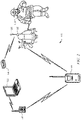
- FIG. 2 illustrates an emergency responder tracking system 110.
- the system 110 includes incident commander 112, an optional RF relay station 114, the RF beacon 100 (breadcrumb), and a portable device 116.
- a wireless protocol such as, for example, BLE, low power wide area network (“LPWAN"), 802.15.4, or combinations thereof, may be a communication protocol for communication between RF beacon 100 and portable device 116.
- a wireless protocol such as, for example, a long range radio may be a communication protocol for communication among the RF relay station 114, the portable device 116, and the incident commander 112.
- the incident commander 112 includes a computer system for monitoring the RF beacon(s) 100 and processing information received from the RF beacon(s) 100 and communication module 113 (e.g., long range radio).
- the incident commander 112 may be manned or unmanned.
- the RF relay station 114 may be an optional component of the system 110.
- the RF relay station(s) 114 may be deployed as needed to increase a communication range between incident commander 112 and the portable device 116.
- the portable device 116 may include long range (e.g., up to about 20 miles) radio 118, and may relay information (e.g., a unique identifier, the RF beacon 100's location (e.g., regional location), last location (e.g., regional location) a firefighter was detected, and/or current time) it receives from the RF beacon 100 to the RF relay station 114 which may relay the information to incident commander 112.
- the RF relay station 114 may be a long range radio configured to relay a signal up to about 20 miles.
- portable device 116 may transmit the information directly to incident commander 112.
- the portable device 116 is worn by an emergency responder, such as, for example, firefighter 119.
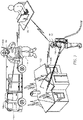
- FIG. 3 illustrates an RF beacon 100a positioned on an emergency vehicle (e.g., fire truck 120), and an RF beacon 100b positioned on structure 122.
- the RF beacon 100a may be activated by firefighter 119a and placed on fire truck 120.
- the firefighter 119a may then notify (e.g., via radio, cell phone) the incident commander 112 of the location of the RF beacon 100a (e.g., describing that the RF beacon 100a is positioned on fire truck 120).
- the RF beacon 100a transmits information including a unique identifier, RF beacon 100a's location (e.g., regional location), last location (e.g., regional location) firefighter 119a was detected, and/or current time, to portable device 116a which relays the information to incident commander 112 via radio 118a.
- location e.g., regional location
- last location e.g., regional location
- the firefighter 119b may activate the RF beacon 100b and place it on structure 122.
- the firefighter 119b may then notify (e.g., via radio, cell phone) incident commander 112 of the location of the RF beacon 100b (e.g., describing that the RF beacon 100b is positioned on structure 122, relaying the firefighter's 119b current location, etc.).
- the RF beacon 100b transmits information including a unique identifier, the RF beacon 100b's location (e.g., regional location), last location (e.g., regional location) firefighter 119b was detected, and/or current time, to portable device 116b which relays the information to incident commander 112 via radio 118b.
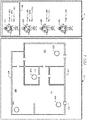
- FIG. 4 illustrates user interface 122 for incident commander 112.
- the user interface 122 may allow for rapid identification and selection of all of the personnel (e.g., firefighters 136, 138, 140, and 142) in the vicinity, and display annotations (e.g., markers) tracking the movement of the personnel (e.g., emergency responders).
- the incident commander 112 may draw floor plans 124 of structure 123 using location descriptions provided by a firefighter and/or the information provided by the RF beacons 100c-100f and display floor plans 124 in user interface 122.
- the floor plans 124 may include a map of the placement/location of each of the RF beacons 100c-100f. As illustrated in FIG.
- a firefighter may enter structure 123 via entrance 125, activate the RF beacons 100c-100f, and place the RF beacon 100c in area 126 (e.g., room, stairwell, or hallway), place 100d in area 128, place 100e in area 130, and place 100fin area 132.
- the firefighter may then contact the incident commander 112 and describe the regional placement/location of each of the RF beacons 100c-100f relative to internal structures, such as, for example, stairs, hallways, rooms, closets, doors, entrance 125, exit, structure level (e.g., second floor or first floor), elevators, furniture, etc.
- the incident commander 112 may then create/draw floor plans 124 based on the regional placement descriptions communicated to incident commander 112 by the firefighter.
- the panel 134 of the user interface 122 may show each firefighter (e.g., firefighter 136, firefighter 138, firefighter 140, firefighter 142) within structure 123.
- the panel 134 may also show the signal strength between each of the RF beacons 100c-100f and a portable device 116.
- the signal strength between the RF beacons 100c-100f and a portable device 116 shown on FIG.
- a firefighter i.e., a firefighter wearing portable device 116
- the signal strength may be calculated by incident commander 112 with a triangulation algorithm. Specific values for distances may depend upon building materials and/or the layout of structure 123.
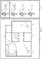
- FIG. 5 illustrates user interface 122 showing an estimated region or vicinity 144 of firefighter 136.
- the user interface 122 may select/highlight (e.g., box 146) a firefighter (e.g., firefighter 136) from a plurality of firefighters (e.g., firefighters 136, 138, 140, and 142) shown in panel 134 when displaying an estimated region (e.g., vicinity 144) for that particular firefighter.
- the signal strength between the RF beacons 100c-100f and a portable device 116 may indicate a vicinity (e.g., vicinity 144) where each firefighter may be located/positioned.
- the vicinity 144 may be shown with a circular graphic.
- the vicinity of each firefighter may be calculated by incident commander 112 with a triangulation algorithm. That is, a telemetry module may receive signals from 3 or more RF beacons 100 and may triangulate an estimated region of each firefighter based on signal strength.
- the signals detected by the firefighters from the RF beacon(s) can be transmitted back to the incident commander, where the signals can be detected and stored along with various identification information for the firefighters, as well as a time stamp.
- a path can be detected for each firefighter such that the relative locations and timings of the firefighters can be traced. This may allow other firefighters to follow a lead firefighter, or the firefighters' position to be tracked over time.
- FIG. 6 illustrates exit route 148 in user interface 122 based on the positions of the RF beacons 100c-100f.
- the incident commander 112 may draw an exit route 148 in user interface 122 for firefighters 136, 138, 140, and/or 142 within structure 123, and direct firefighters 136, 138, 140, and/or 142 to exit 150 based on signal strength between a portable device 116 of each of firefighters 136, 138, 140, 142, and the RF beacons 100c-100f.
- the incident commander 112 may also direct (e.g., via radio) each of the firefighters 136, 138, 140, and/or 142 to exit 150 based on the descriptions of the locations of each of the RF beacons 100c-100f.
- each of the firefighters 136, 138, 140, and/or 142 may have communicated to incident commander 112, a description of the location of each of the RF beacons 100c-100f during activation and positioning of RF beacons 100c-100f.
- the positions can then be used to locate and direct the firefighters to a position such as an exit, or the location of a firefighter who is in trouble or is injured.
Description
- The location of people and objects inside an environment, such as, for example, a building may be important. However, the cost of acquiring location data should not be prohibitive. Systems that can send and receive signals, and then process the signals to provide a location can be expensive. Reducing the cost of such systems is desirable.
-
US 7,598,856 B1 discloses a navigation system for navigating in low visibility environments, including a portable detection unit which uses position and orientation sensors and/or wireless location to track the position of the portable detection unit relative to some reference location, such as a fire truck. The relative position of the portable detection unit, and thus its user, is then output to a visual display for viewing by the user so that the user may see his/her position in a dark or smoky environment. The system may also include portable beacons which may be left at landmarks so that the relative positions of the landmarks may be seen on the visual display. - Aspects of the invention are set out in the appended claims.
- For a more complete understanding of the present disclosure, reference is now made to the following brief description, taken in connection with the accompanying drawings and detailed description, wherein like reference numerals represent like parts.
-
FIG. 1 is a schematic illustration of an RF beacon of an emergency responder tracking system according to embodiments of the present invention. -
FIG. 2 is a schematic illustration of the emergency responder tracking system according to embodiments of the present invention. -
FIG. 3 is a schematic illustration of an RF beacon positioned on an emergency vehicle not according to the present invention. -
FIG. 4 is a schematic illustration of a user interface displayed on a computer system of the emergency responder tracking system according to embodiments of the present invention. -
FIG. 5 is a schematic illustration of a user interface displayed on the computer system of the emergency responder tracking system according to embodiments of the present invention. The user interface shows an estimated region of an emergency responder. -
FIG. 6 is a schematic illustration of a user interface displayed on the computer system of the emergency responder tracking system according to embodiments of the present invention. The user interface shows an exit route. - It should be understood at the outset that although illustrative implementations are illustrated below, the disclosed systems and methods may be implemented using any number of techniques, whether currently known or not yet in existence. The disclosure should in no way be limited to the illustrative implementations, drawings, and techniques illustrated below, but may be modified within the scope of the appended claims
- The following brief definition of terms shall apply throughout the application:
- The term "comprising" means including but not limited to, and should be interpreted in the manner it is typically used in the patent context;
- If the specification describes something as "exemplary" or an "example," it should be understood that refers to a non-exclusive example;
- The terms "about" or "approximately" or the like, when used with a number, may mean that specific number, or alternatively, a range in proximity to the specific number, as understood by persons of skill in the art field; and
- If the specification states a component or feature "may," "can," "could," "should," "would," "preferably," "possibly," "typically," "optionally," "for example," "often," or "might" (or other such language) be included or have a characteristic, that particular component or feature is not required to be included or to have the characteristic. Such component or feature may be optionally included, or it may be excluded.
- Locating firefighters and emergency workers on the grounds of an active incident has been a key unmet need for some time. Precise location and tracking has been demonstrated to be feasible, but is currently orders of magnitude beyond acceptable cost targets. While some systems such as a Global Positioning System (GPS) could be used, such systems may not work within a closed structure. In addition, such systems often consume large amounts of power from the devices carried by the firefighters and emergency works. Most frequently, incident commanders may need to know the vicinity (e.g., side of the building, floor of the building) of a team member, rather than an exact position.
- The disclosure provides a simple-to-deploy system for identifying key regions and providing automated information on the time and last known position for accountability and directing search and rescue operations. Firefighter or emergency workers may cany portable systems (e.g., a self-contained breathing apparatus ("SCBA")) that can include a low cost, low power radio frequency ("RF") transceiver. These simple, disposable, low cost RF beacons may be provided to key members of a firefighting team, as they enter and move around a structure. At key points inside or outside the structure, the firefighters may take one of the RF beacons, activate the RF beacon (e.g., by turning
dial 104, etc.), and mount it to a surrounding structure. Upon activating the RF beacon, the RF beacon may begin transmitting a signal (e.g., wireless) providing its identification and/or location. The RF beacon may have a simple mounting mechanism (e.g., screws, bolts, straps, adhesive, or combinations thereof) to allow mounting of the RF beacon on many internal or external structures, such as, for example, a wall, door, siding, tree, telephone pole, etc. When a firefighter activates and attaches the RF beacon to a surrounding structure, the firefighter may also contact the incident commander and indicate the location of the RF beacon and verify its correct operation. The incident commander may maintain a map containing the locations of all of the RF beacons deployed, or list the location of each of the RF beacons using software integrated to an incident commander (e.g., a computer). Since the signal for the RF beacon may not travel significant distances; when subsequent firefighters pass through the same vicinity, their portable systems may detect the RF beacon and may relay the identification of the RF beacon back to the incident commander. Since the RF signal may travel a short distance, the incident commander can precisely note the place and time the firefighter was at that location associated with the specific RF beacon. Additional uses of the RF beacons may include mounting the RF beacons on rocks or heavy objects that can be thrown into a structure. If the RF beacon is thrown into the vicinity of a lost firefighter, the relay of the RF beacon identification can be used to confirm the firefighter's position. -
FIG. 1 is a schematic illustration of anRF beacon 100. TheRF beacon 100 includes anRF module 102 configured to communicate via radio frequencies. TheRF beacon 100 may also includedial 104 for turning theRF beacon 100 on/offDial 104 may also be utilized to set an address (e.g., a unique address) of the location of theRF beacon 100.Dial 104 may set the address via a color coding scheme (e.g., a specific color for a specific location, set by the factory/manufacturing facility or automatically set by a firefighter's system/equipment). TheRF beacon 100 may have a length, L, from about 1.5 inches to about 3 inches; a width, W, from about 1 inch to about 2 inches; and a height, H, from about 0.5 inch to about 1 inch. TheRF beacon 100 may be of any suitable shape, such as, for example, a polyhedron (e.g., cube, rectangular prism, a triangular prism). TheRF beacon 100 may operate using a battery having a suitable voltage (e.g., a 3 volt battery, etc.) and may be waterproof and/or heat resistant up to about 600°F. TheRF beacon 100 may be constructed in a minimally insulated package allowing it to survive for a short time period in a fire situation in order to transmit signals that can be relayed (e.g., through a portable device, etc.) back to an incident commander (e.g.,incident commander 112 shown onFIG. 2 ). - The
RF beacon 100 may be a low power radio/battery combination that uses one of many wireless protocols, such as, for example, low power protocols such as Bluetooth Low Energy ("BLE"), low power wide area network ("LPWAN"), 802.15.4, or combinations thereof. Turningdial 104 to an ON position may cause theRF beacon 100 to start transmitting a signal including information, such as, for example, a unique identifier, theRF beacon 100's location (e.g., a regional location, room identifier, site location, etc.), last location a firefighter was detected, and/or current time. This signal may be immediately received by the firefighter'sportable device 116 mounted telemetry module (e.g., a SCBA mounted telemetry module shown onFIG. 2 , a safety communicator comprising a portable communication device capable of using cellular communication protocols, etc.) and relayed to the incident commander. Data can be transmitted from the portable device to the RF beacon to be stored. For example, a location estimate, or any of the other information listed herein, provided by the portable device can be provided to the RF beacon, which can then be transmitted as part of the RF beacon transmission. - Using a voice radio or other digital means, the user may indicate an area the
RF beacon 100 has been mounted in. For example, a notification at the time the RF beacon is deployed can communicate the latest location determination of the portable device, which may be reasonably close to the location of theRF beacon 100 to serve as the location estimate. Subsequent firefighters coming into the same vicinity may detect theRF beacon 100 with their respective portable devices and relay information received from theRF beacon 100 to the incident commander. The transmitted information including the unique identifier, theRF beacon 100's location, a last location a firefighter was detected, and/or current time may be logged by the incident commander. - The
RF beacon 100 may be utilized as a location marker. That is, at key points inside or outside a structure (e.g., a building), a user (e.g., an emergency responder such as a firefighter) may take theRF beacon 100, activate theRF beacon 100 by turningdial 104 to an ON position, and attaching/mounting/positioning theRF beacon 100 on a surrounding structure (e.g., wall, floor, ceiling, furniture) within a building. Thedial 104 may be graspable by gloved hands (e.g., insulated gloves substantially larger than a human hand, such as firefighter gloves). Upon activating theRF beacon 100, theRF beacon 100 may begin transmitting, a signal including information, such as, for example, a unique identifier, theRF beacon 100's location (e.g., regional location), last location (e.g., regional location) a firefighter was detected, and/or current time. TheRF beacon 100 may include a simple mounting mechanism (e.g., screws, bolts, straps, adhesive, or combinations thereof) to allow mounting ofRF beacon 100 on many internal and/or external structures, such as, for example, a wall, door, siding, tree, telephone pole, etc. TheRF beacon 100 may also be placed/attached to vehicles (e.g., a fire truck) to identify a recovery area, nearness to trucks, etc. TheRF beacon 100 may indicate that a user is outside of a structure or inside a structure based on signal strength between theRF beacon 100 andportable device 116. When a firefighter activates and attaches theRF beacon 100 to a structure, the firefighter may also contact an incident commander (e.g., a computer system for monitoring RF beacon(s) 100 and processing information received from RF beacon(s) 100) and provide a description of the location of theRF beacon 100 and verify that theRF beacon 100 is operating correctly. The incident commander may maintain a map containing the locations/positions of theRF beacons 100 deployed, or list the location of eachRF beacon 100 by using software integrated toincident commander 112. Since signals from/to theRF beacon 100 may not travel significant distances (e.g., up to about 30 feet), when subsequent firefighters pass through the same vicinity, theirportable device 116 detect theRF beacon 100 and relay information including the unique identifier, theRF beacon 100's location (e.g., regional location), last location (e.g., regional location) a firefighter was detected, and/or current time toincident commander 112. Since the RF signal may travel a short distance,incident commander 112 can precisely or approximately note the place and time each firefighter was at that location. Additional uses of theRF beacons 100 may include mounting theRF beacons 100 on rocks or heavy objects that can be thrown into a structure. If theRF beacon 100 is activated and thrown/deployed into the vicinity of a lost firefighter, confirmation of the firefighter's position can be established. That is, theRF beacon 100 may be thrown into, for example, windows where a lost firefighter is thought to be, and may indicate a presence of the lost firefighter based on signal strength betweenRF beacon 100 and aportable device 116. Signal strength may indicate whether a firefighter is located at a near distance, a medium distance, or a far distance from theRF beacon 100. TheRF beacon 100 may contain a color code wheel numbering system to allow the incident commander to identify the locations of the RF beacon(s) 100. -
FIG. 2 illustrates an emergencyresponder tracking system 110. Thesystem 110 includesincident commander 112, an optionalRF relay station 114, the RF beacon 100 (breadcrumb), and aportable device 116. A wireless protocol, such as, for example, BLE, low power wide area network ("LPWAN"), 802.15.4, or combinations thereof, may be a communication protocol for communication betweenRF beacon 100 andportable device 116. A wireless protocol, such as, for example, a long range radio may be a communication protocol for communication among theRF relay station 114, theportable device 116, and theincident commander 112. - The
incident commander 112 includes a computer system for monitoring the RF beacon(s) 100 and processing information received from the RF beacon(s) 100 and communication module 113 (e.g., long range radio). Theincident commander 112 may be manned or unmanned. TheRF relay station 114 may be an optional component of thesystem 110. The RF relay station(s) 114 may be deployed as needed to increase a communication range betweenincident commander 112 and theportable device 116. Theportable device 116 may include long range (e.g., up to about 20 miles)radio 118, and may relay information (e.g., a unique identifier, theRF beacon 100's location (e.g., regional location), last location (e.g., regional location) a firefighter was detected, and/or current time) it receives from theRF beacon 100 to theRF relay station 114 which may relay the information toincident commander 112. For example, theRF relay station 114 may be a long range radio configured to relay a signal up to about 20 miles. Alternatively,portable device 116 may transmit the information directly toincident commander 112. Theportable device 116 is worn by an emergency responder, such as, for example,firefighter 119. -
FIG. 3 illustrates anRF beacon 100a positioned on an emergency vehicle (e.g., fire truck 120), and anRF beacon 100b positioned onstructure 122. TheRF beacon 100a may be activated byfirefighter 119a and placed onfire truck 120. Thefirefighter 119a may then notify (e.g., via radio, cell phone) theincident commander 112 of the location of theRF beacon 100a (e.g., describing that theRF beacon 100a is positioned on fire truck 120). TheRF beacon 100a transmits information including a unique identifier,RF beacon 100a's location (e.g., regional location), last location (e.g., regional location)firefighter 119a was detected, and/or current time, toportable device 116a which relays the information toincident commander 112 viaradio 118a. - The
firefighter 119b may activate theRF beacon 100b and place it onstructure 122. Thefirefighter 119b may then notify (e.g., via radio, cell phone)incident commander 112 of the location of theRF beacon 100b (e.g., describing that theRF beacon 100b is positioned onstructure 122, relaying the firefighter's 119b current location, etc.). TheRF beacon 100b transmits information including a unique identifier, theRF beacon 100b's location (e.g., regional location), last location (e.g., regional location)firefighter 119b was detected, and/or current time, toportable device 116b which relays the information toincident commander 112 viaradio 118b. -
FIG. 4 illustratesuser interface 122 forincident commander 112. Theuser interface 122 may allow for rapid identification and selection of all of the personnel (e.g.,firefighters incident commander 112 may drawfloor plans 124 ofstructure 123 using location descriptions provided by a firefighter and/or the information provided by theRF beacons 100c-100f anddisplay floor plans 124 inuser interface 122. The floor plans 124 may include a map of the placement/location of each of theRF beacons 100c-100f. As illustrated inFIG. 4 , a firefighter may enterstructure 123 viaentrance 125, activate theRF beacons 100c-100f, and place theRF beacon 100c in area 126 (e.g., room, stairwell, or hallway),place 100d inarea 128,place 100e inarea 130, andplace 100fin area 132. The firefighter may then contact theincident commander 112 and describe the regional placement/location of each of theRF beacons 100c-100f relative to internal structures, such as, for example, stairs, hallways, rooms, closets, doors,entrance 125, exit, structure level (e.g., second floor or first floor), elevators, furniture, etc. Theincident commander 112 may then create/draw floor plans 124 based on the regional placement descriptions communicated toincident commander 112 by the firefighter. Thepanel 134 of theuser interface 122 may show each firefighter (e.g.,firefighter 136,firefighter 138,firefighter 140, firefighter 142) withinstructure 123. Thepanel 134 may also show the signal strength between each of theRF beacons 100c-100f and aportable device 116. The signal strength between theRF beacons 100c-100f and a portable device 116 (shown onFIG. 2 ) may indicate whether a firefighter (i.e., a firefighter wearing portable device 116) is located at a near distance, a medium distance, or a far distance from each of theRF beacons 100c-100f, as shown inpanel 134. The signal strength may be calculated byincident commander 112 with a triangulation algorithm. Specific values for distances may depend upon building materials and/or the layout ofstructure 123. -
FIG. 5 illustratesuser interface 122 showing an estimated region orvicinity 144 offirefighter 136. Theuser interface 122 may select/highlight (e.g., box 146) a firefighter (e.g., firefighter 136) from a plurality of firefighters (e.g.,firefighters panel 134 when displaying an estimated region (e.g., vicinity 144) for that particular firefighter. The signal strength between theRF beacons 100c-100f and a portable device 116 (shown onFIG. 2 ) may indicate a vicinity (e.g., vicinity 144) where each firefighter may be located/positioned. Thevicinity 144 may be shown with a circular graphic. The vicinity of each firefighter may be calculated byincident commander 112 with a triangulation algorithm. That is, a telemetry module may receive signals from 3 ormore RF beacons 100 and may triangulate an estimated region of each firefighter based on signal strength. - During use, the signals detected by the firefighters from the RF beacon(s) can be transmitted back to the incident commander, where the signals can be detected and stored along with various identification information for the firefighters, as well as a time stamp. Upon passing by a plurality of RF beacons, a path can be detected for each firefighter such that the relative locations and timings of the firefighters can be traced. This may allow other firefighters to follow a lead firefighter, or the firefighters' position to be tracked over time.
-
FIG. 6 illustratesexit route 148 inuser interface 122 based on the positions of theRF beacons 100c-100f. Theincident commander 112 may draw anexit route 148 inuser interface 122 forfirefighters structure 123, anddirect firefighters portable device 116 of each offirefighters RF beacons 100c-100f. Theincident commander 112 may also direct (e.g., via radio) each of thefirefighters RF beacons 100c-100f. That is, as previously mentioned, each of thefirefighters incident commander 112, a description of the location of each of theRF beacons 100c-100f during activation and positioning ofRF beacons 100c-100f. The positions can then be used to locate and direct the firefighters to a position such as an exit, or the location of a firefighter who is in trouble or is injured. - While various techniques, systems, subsystems, and methods in accordance with the principles disclosed herein have been shown and described above, modifications thereof may be made by one skilled in the art. The techniques, systems, subsystems, and methods described herein are representative only and are not intended to be limiting. Many variations, combinations, and modifications are possible and are within the scope of the disclosure. Alternatives that result from combining, integrating, and/or omitting features are also within the scope of the disclosure. Accordingly, the scope of protection is not limited by the description set out above, but is defined by the claims which follow. Furthermore, any advantages and features described above shall not limit the application of such issued claims to processes and structures accomplishing any or all of the above advantages or having any or all of the above features.
- Use of broader terms such as "comprises," "includes," and "having" should be understood to provide support for narrower terms such as "consisting of," "consisting essentially of," and "comprised substantially of." Use of the terms "optionally," "may," "might," "possibly," and the like with respect to any element means that the element is not required, or alternatively, the element is required. Also, references to examples are merely provided for illustrative purposes, and are not intended to be exclusive.
- It should be understood that the disclosed systems and methods may be embodied in many other specific forms. The present examples are to be considered as illustrative and not restrictive, and the intention is not to be limited to the details given herein. For example, the various elements or components may be combined or integrated in another system or certain features may be omitted or not implemented.
- Also, techniques, systems, subsystems, and methods described and illustrated as discrete or separate may be combined or integrated with other systems, modules, techniques, or methods. Other items shown or discussed as directly coupled or communicating with each other may be indirectly coupled or communicating through some interface, device, or intermediate component, whether electrically, mechanically, or otherwise. Other examples of changes, substitutions, and alterations are ascertainable by one skilled in the art and could be made without departing from the scope as defined by the appended claims.
Claims (11)
- An emergency responder tracking system comprising:a computer system comprising a user interface (122);a plurality of portable beacons (100) comprising a radio frequency module (102) having a first range for communication;a portable device (116) that in use is worn by an emergency responder, the portable device (116) comprising a transceiver, wherein the portable device (116) is configured to receive a wireless signal from a portable beacon (100) of the plurality of portable beacons (100) when within the first range and transmit the wireless signal to the computer system within a second range greater than the first range;wherein the computer system is configured to:receive the wireless signal from the portable device (116);receive a description of a placement of the portable beacon (100) relative to a building;determine a location of the portable beacon (100) based on the description; anddisplay, on the user interface (122), the location of the portable beacon (100);wherein the wireless signal comprises a unique identifier, the location of the portable beacon (100), a last detected location of the emergency responder, and/or current time; andwherein the plurality of portable beacons (100) is configured for attachment to a structure within the building.
- The emergency responder tracking system of claim 1, wherein the portable device (116) is mounted on a self-contained breathing apparatus associated with an emergency responder.
- The emergency responder tracking system of claim 1, further comprising a radio frequency relay station (114) configured to receive the wireless signal from the portable device (116) and transmit the wireless signal to the computer system over a predetermined distance.
- The emergency responder tracking system of claim 1, wherein the computer system is configured to allow identification of at least one emergency responder within a predetermined vicinity of the building.
- The emergency responder tracking system of claim 1, wherein the user interface (122) is configured to display markers tracking movement of at least one emergency responder.
- The emergency responder tracking system of claim 5, wherein the user interface (122) is configured to indicate a predetermined vicinity, with a circular graphic, of the at least one emergency responder.
- The emergency responder tracking system of claim 1, wherein the computer system is configured to use a signal strength between the portable beacon (100) and the portable device (116) to determine a distance between the beacon (100) and the portable device (116).
- The emergency responder tracking system of claim 1, wherein the portable beacon (100) is configured to be mounted to structures by screws, bolts, straps, adhesive, or combinations thereof.
- The emergency responder tracking system of claim 1, wherein the portable beacon (100) comprises a dial to activate the beacon (100).
- The emergency responder tracking system of claim 1, wherein a wireless protocol for communication between the portable beacon (100) and the portable device (116) is BLUETOOTH low energy, low power wide area network, 802.15.4, or combinations thereof.
- A method for tracking an emergency responder comprising:attaching a plurality of portable beacons (100) within a building at a plurality of locations, wherein each portable beacon (100) of the plurality of portable beacons (100) comprises a radio frequency module (102) having a first range for communication;activating each portable beacon (100); communicating to a computer system a description of a placement of each portable beacon (100);detecting each portable beacon (100) by a portable device (116) that is within the first range and that is worn by an emergency responder moving within the building, wherein the portable device (116) has a second range for communication greater than the first range;transmitting information from each portable beacon (100) to the portable device (116) within the first range;transmitting the information from the portable device (116) to the computer system within the second range;displaying in a user interface (122), locations of each portable beacon (100); andtracking a location of the portable device (116) based on the information transmitted from the portable device (116) to the computer system.
Applications Claiming Priority (2)
| Application Number | Priority Date | Filing Date | Title |
|---|---|---|---|
| US15/634,044 US10129704B1 (en) | 2017-06-27 | 2017-06-27 | First responder tracking breadcrumbs |
| EP18180184.6A EP3422039B1 (en) | 2017-06-27 | 2018-06-27 | First responder tracking breadcrumbs |
Related Parent Applications (1)
| Application Number | Title | Priority Date | Filing Date |
|---|---|---|---|
| EP18180184.6A Division EP3422039B1 (en) | 2017-06-27 | 2018-06-27 | First responder tracking breadcrumbs |
Publications (2)
| Publication Number | Publication Date |
|---|---|
| EP3687196A1 EP3687196A1 (en) | 2020-07-29 |
| EP3687196B1 true EP3687196B1 (en) | 2022-08-17 |
Family
ID=62916412
Family Applications (2)
| Application Number | Title | Priority Date | Filing Date |
|---|---|---|---|
| EP20164449.9A Active EP3687196B1 (en) | 2017-06-27 | 2018-06-27 | First responder tracking breadcrumbs |
| EP18180184.6A Active EP3422039B1 (en) | 2017-06-27 | 2018-06-27 | First responder tracking breadcrumbs |
Family Applications After (1)
| Application Number | Title | Priority Date | Filing Date |
|---|---|---|---|
| EP18180184.6A Active EP3422039B1 (en) | 2017-06-27 | 2018-06-27 | First responder tracking breadcrumbs |
Country Status (2)
| Country | Link |
|---|---|
| US (1) | US10129704B1 (en) |
| EP (2) | EP3687196B1 (en) |
Families Citing this family (7)
| Publication number | Priority date | Publication date | Assignee | Title |
|---|---|---|---|---|
| WO2018094229A1 (en) | 2016-11-17 | 2018-05-24 | Lorenzo LO MONTE | Radio frequency identification (rfid) system for determining location |
| US11144867B2 (en) * | 2017-11-30 | 2021-10-12 | DoorDash, Inc. | Predictions by using beacons in a real-time last mile logistics platform |
| US10872584B2 (en) * | 2019-03-14 | 2020-12-22 | Curious Company, LLC | Providing positional information using beacon devices |
| US11263891B2 (en) * | 2019-05-15 | 2022-03-01 | Skydome Ab | Enhanced emergency response |
| US11783694B2 (en) | 2019-08-08 | 2023-10-10 | 3M Innovative Properties Company | Determining responder closest to downed responder |
| CN112601184B (en) * | 2020-12-18 | 2021-08-20 | 西安电子科技大学 | Portable field mobile emergency communication system |
| US11810050B2 (en) * | 2021-08-20 | 2023-11-07 | Ford Global Technologies, Llc | Robotic package delivery with ad-hoc network fusion localization |
Citations (1)
| Publication number | Priority date | Publication date | Assignee | Title |
|---|---|---|---|---|
| US20080211906A1 (en) * | 2005-02-16 | 2008-09-04 | Ivan Lovric | Intelligent Remote Multi-Communicating Surveillance System And Method |
Family Cites Families (13)
| Publication number | Priority date | Publication date | Assignee | Title |
|---|---|---|---|---|
| US5898363A (en) * | 1997-03-05 | 1999-04-27 | Safety Systems, Inc. | Portable audible beacon |
| AU1125300A (en) * | 1998-10-22 | 2000-05-08 | University Of Maryland | Method and system for providing location dependent and personal identification information to a public safety answering point |
| US7398097B2 (en) * | 2002-12-23 | 2008-07-08 | Scott Technologies, Inc. | Dual-mesh network and communication system for emergency services personnel |
| US7177623B2 (en) * | 2003-07-02 | 2007-02-13 | The United States Of America As Represented By The Secretary Of The Army | Localized cellular awareness and tracking of emergencies |
| US7135967B2 (en) * | 2003-08-01 | 2006-11-14 | Spectrum Tracking Systems, Inc. | Method for locating an asset |
| US7899583B2 (en) | 2005-04-12 | 2011-03-01 | Ehud Mendelson | System and method of detecting and navigating to empty parking spaces |
| US7598856B1 (en) | 2006-01-31 | 2009-10-06 | Firesite Llc | Navigation aid for low-visibility environments |
| US8688375B2 (en) * | 2006-05-31 | 2014-04-01 | Trx Systems, Inc. | Method and system for locating and monitoring first responders |
| US20080122696A1 (en) | 2006-11-28 | 2008-05-29 | Huseth Steve D | Low cost fire fighter tracking system |
| US9717065B2 (en) * | 2013-12-20 | 2017-07-25 | Apple Inc. | Indoor remote triggered location scanning |
| US9494674B2 (en) | 2014-03-03 | 2016-11-15 | Safetracks Gps Canada Inc. | Personal locator beacon system |
| WO2017100686A1 (en) * | 2015-12-11 | 2017-06-15 | Patrocinium Systems, Llc | Secure beacon-based location systems and methods |
| US10142772B2 (en) * | 2015-12-16 | 2018-11-27 | Qualcomm Incorporated | Systems and methods for emergency data communication |
-
2017
- 2017-06-27 US US15/634,044 patent/US10129704B1/en active Active
-
2018
- 2018-06-27 EP EP20164449.9A patent/EP3687196B1/en active Active
- 2018-06-27 EP EP18180184.6A patent/EP3422039B1/en active Active
Patent Citations (1)
| Publication number | Priority date | Publication date | Assignee | Title |
|---|---|---|---|---|
| US20080211906A1 (en) * | 2005-02-16 | 2008-09-04 | Ivan Lovric | Intelligent Remote Multi-Communicating Surveillance System And Method |
Also Published As
| Publication number | Publication date |
|---|---|
| EP3687196A1 (en) | 2020-07-29 |
| EP3422039B1 (en) | 2020-04-08 |
| EP3422039A1 (en) | 2019-01-02 |
| US10129704B1 (en) | 2018-11-13 |
Similar Documents
| Publication | Publication Date | Title |
|---|---|---|
| EP3687196B1 (en) | First responder tracking breadcrumbs | |
| US11232702B2 (en) | Automated sensing of firefighter teams | |
| US10147295B2 (en) | Personnel tracking and monitoring system and method employing protective gear including a personnel electronic monitor device | |
| AU2021201818B2 (en) | Tracking and accountability device and system | |
| CN109275097B (en) | Indoor positioning and monitoring system based on UWB | |
| US7327252B2 (en) | Emergency rescuer tracking system and method | |
| US20080122696A1 (en) | Low cost fire fighter tracking system | |
| JP2008111828A (en) | Portable positioning and navigation system | |
| EP3064899A1 (en) | Tracking in an indoor environment | |
| JP6080568B2 (en) | Monitoring system | |
| US20080186161A1 (en) | System and method for tracking, locating, and guiding personnel at a location | |
| Di Giampaolo | A passive-RFID based indoor navigation system for visually impaired people | |
| WO2012143952A2 (en) | A system and apparatus for safe remote on-line tracing, shadowing, surveillance, inter-communication, location, navigation, tagging, rescue, recovery and restitution of humans and stolen/missing chattels, and the method/s thereof | |
| EP2597423A1 (en) | Indoor navigation and localisation system and method to locate a mobile unit | |
| US9858791B1 (en) | Tracking and accountability device and system | |
| US20070194910A1 (en) | Real time personnel location system and method | |
| KR20150121341A (en) | Building energy management and rescue system using living body signal | |
| Pascucci et al. | A REference implementation of interoperable indoor location & communication systems for First REsponders: The REFIRE project | |
| US20070040743A1 (en) | Method and arrangement for locating people | |
| KR102026704B1 (en) | Luggage location notification system using distance sensor and luggage location notifying method using distance sensor | |
| WO2015015371A1 (en) | Security system for users and equipment |
Legal Events
| Date | Code | Title | Description |
|---|---|---|---|
| PUAI | Public reference made under article 153(3) epc to a published international application that has entered the european phase |
Free format text: ORIGINAL CODE: 0009012 |
|
| STAA | Information on the status of an ep patent application or granted ep patent |
Free format text: STATUS: THE APPLICATION HAS BEEN PUBLISHED |
|
| AC | Divisional application: reference to earlier application |
Ref document number: 3422039 Country of ref document: EP Kind code of ref document: P |
|
| AK | Designated contracting states |
Kind code of ref document: A1 Designated state(s): AL AT BE BG CH CY CZ DE DK EE ES FI FR GB GR HR HU IE IS IT LI LT LU LV MC MK MT NL NO PL PT RO RS SE SI SK SM TR |
|
| STAA | Information on the status of an ep patent application or granted ep patent |
Free format text: STATUS: REQUEST FOR EXAMINATION WAS MADE |
|
| 17P | Request for examination filed |
Effective date: 20210122 |
|
| RBV | Designated contracting states (corrected) |
Designated state(s): AL AT BE BG CH CY CZ DE DK EE ES FI FR GB GR HR HU IE IS IT LI LT LU LV MC MK MT NL NO PL PT RO RS SE SI SK SM TR |
|
| GRAP | Despatch of communication of intention to grant a patent |
Free format text: ORIGINAL CODE: EPIDOSNIGR1 |
|
| STAA | Information on the status of an ep patent application or granted ep patent |
Free format text: STATUS: GRANT OF PATENT IS INTENDED |
|
| RIC1 | Information provided on ipc code assigned before grant |
Ipc: G08B 7/06 20060101ALN20220208BHEP Ipc: G06Q 50/10 20120101ALI20220208BHEP Ipc: G08B 21/02 20060101ALI20220208BHEP Ipc: A62C 99/00 20100101ALI20220208BHEP Ipc: G01C 21/20 20060101ALI20220208BHEP Ipc: H04W 4/33 20180101ALI20220208BHEP Ipc: H04W 4/80 20180101ALI20220208BHEP Ipc: H04W 4/90 20180101ALI20220208BHEP Ipc: H04W 4/029 20180101AFI20220208BHEP |
|
| RIC1 | Information provided on ipc code assigned before grant |
Ipc: G08B 7/06 20060101ALN20220221BHEP Ipc: G06Q 50/10 20120101ALI20220221BHEP Ipc: G08B 21/02 20060101ALI20220221BHEP Ipc: A62C 99/00 20100101ALI20220221BHEP Ipc: G01C 21/20 20060101ALI20220221BHEP Ipc: H04W 4/33 20180101ALI20220221BHEP Ipc: H04W 4/80 20180101ALI20220221BHEP Ipc: H04W 4/90 20180101ALI20220221BHEP Ipc: H04W 4/029 20180101AFI20220221BHEP |
|
| INTG | Intention to grant announced |
Effective date: 20220310 |
|
| GRAS | Grant fee paid |
Free format text: ORIGINAL CODE: EPIDOSNIGR3 |
|
| GRAA | (expected) grant |
Free format text: ORIGINAL CODE: 0009210 |
|
| STAA | Information on the status of an ep patent application or granted ep patent |
Free format text: STATUS: THE PATENT HAS BEEN GRANTED |
|
| AC | Divisional application: reference to earlier application |
Ref document number: 3422039 Country of ref document: EP Kind code of ref document: P |
|
| AK | Designated contracting states |
Kind code of ref document: B1 Designated state(s): AL AT BE BG CH CY CZ DE DK EE ES FI FR GB GR HR HU IE IS IT LI LT LU LV MC MK MT NL NO PL PT RO RS SE SI SK SM TR |
|
| REG | Reference to a national code |
Ref country code: CH Ref legal event code: EP |
|
| REG | Reference to a national code |
Ref country code: DE Ref legal event code: R096 Ref document number: 602018039568 Country of ref document: DE |
|
| REG | Reference to a national code |
Ref country code: IE Ref legal event code: FG4D |
|
| REG | Reference to a national code |
Ref country code: AT Ref legal event code: REF Ref document number: 1512950 Country of ref document: AT Kind code of ref document: T Effective date: 20220915 |
|
| REG | Reference to a national code |
Ref country code: NL Ref legal event code: MP Effective date: 20220817 |
|
| REG | Reference to a national code |
Ref country code: LT Ref legal event code: MG9D |
|
| PG25 | Lapsed in a contracting state [announced via postgrant information from national office to epo] |
Ref country code: SE Free format text: LAPSE BECAUSE OF FAILURE TO SUBMIT A TRANSLATION OF THE DESCRIPTION OR TO PAY THE FEE WITHIN THE PRESCRIBED TIME-LIMIT Effective date: 20220817 Ref country code: RS Free format text: LAPSE BECAUSE OF FAILURE TO SUBMIT A TRANSLATION OF THE DESCRIPTION OR TO PAY THE FEE WITHIN THE PRESCRIBED TIME-LIMIT Effective date: 20220817 Ref country code: PT Free format text: LAPSE BECAUSE OF FAILURE TO SUBMIT A TRANSLATION OF THE DESCRIPTION OR TO PAY THE FEE WITHIN THE PRESCRIBED TIME-LIMIT Effective date: 20221219 Ref country code: NO Free format text: LAPSE BECAUSE OF FAILURE TO SUBMIT A TRANSLATION OF THE DESCRIPTION OR TO PAY THE FEE WITHIN THE PRESCRIBED TIME-LIMIT Effective date: 20221117 Ref country code: NL Free format text: LAPSE BECAUSE OF FAILURE TO SUBMIT A TRANSLATION OF THE DESCRIPTION OR TO PAY THE FEE WITHIN THE PRESCRIBED TIME-LIMIT Effective date: 20220817 Ref country code: LV Free format text: LAPSE BECAUSE OF FAILURE TO SUBMIT A TRANSLATION OF THE DESCRIPTION OR TO PAY THE FEE WITHIN THE PRESCRIBED TIME-LIMIT Effective date: 20220817 Ref country code: LT Free format text: LAPSE BECAUSE OF FAILURE TO SUBMIT A TRANSLATION OF THE DESCRIPTION OR TO PAY THE FEE WITHIN THE PRESCRIBED TIME-LIMIT Effective date: 20220817 Ref country code: FI Free format text: LAPSE BECAUSE OF FAILURE TO SUBMIT A TRANSLATION OF THE DESCRIPTION OR TO PAY THE FEE WITHIN THE PRESCRIBED TIME-LIMIT Effective date: 20220817 |
|
| REG | Reference to a national code |
Ref country code: AT Ref legal event code: MK05 Ref document number: 1512950 Country of ref document: AT Kind code of ref document: T Effective date: 20220817 |
|
| PG25 | Lapsed in a contracting state [announced via postgrant information from national office to epo] |
Ref country code: PL Free format text: LAPSE BECAUSE OF FAILURE TO SUBMIT A TRANSLATION OF THE DESCRIPTION OR TO PAY THE FEE WITHIN THE PRESCRIBED TIME-LIMIT Effective date: 20220817 Ref country code: IS Free format text: LAPSE BECAUSE OF FAILURE TO SUBMIT A TRANSLATION OF THE DESCRIPTION OR TO PAY THE FEE WITHIN THE PRESCRIBED TIME-LIMIT Effective date: 20221217 Ref country code: HR Free format text: LAPSE BECAUSE OF FAILURE TO SUBMIT A TRANSLATION OF THE DESCRIPTION OR TO PAY THE FEE WITHIN THE PRESCRIBED TIME-LIMIT Effective date: 20220817 Ref country code: GR Free format text: LAPSE BECAUSE OF FAILURE TO SUBMIT A TRANSLATION OF THE DESCRIPTION OR TO PAY THE FEE WITHIN THE PRESCRIBED TIME-LIMIT Effective date: 20221118 |
|
| PG25 | Lapsed in a contracting state [announced via postgrant information from national office to epo] |
Ref country code: SM Free format text: LAPSE BECAUSE OF FAILURE TO SUBMIT A TRANSLATION OF THE DESCRIPTION OR TO PAY THE FEE WITHIN THE PRESCRIBED TIME-LIMIT Effective date: 20220817 Ref country code: RO Free format text: LAPSE BECAUSE OF FAILURE TO SUBMIT A TRANSLATION OF THE DESCRIPTION OR TO PAY THE FEE WITHIN THE PRESCRIBED TIME-LIMIT Effective date: 20220817 Ref country code: ES Free format text: LAPSE BECAUSE OF FAILURE TO SUBMIT A TRANSLATION OF THE DESCRIPTION OR TO PAY THE FEE WITHIN THE PRESCRIBED TIME-LIMIT Effective date: 20220817 Ref country code: DK Free format text: LAPSE BECAUSE OF FAILURE TO SUBMIT A TRANSLATION OF THE DESCRIPTION OR TO PAY THE FEE WITHIN THE PRESCRIBED TIME-LIMIT Effective date: 20220817 Ref country code: CZ Free format text: LAPSE BECAUSE OF FAILURE TO SUBMIT A TRANSLATION OF THE DESCRIPTION OR TO PAY THE FEE WITHIN THE PRESCRIBED TIME-LIMIT Effective date: 20220817 Ref country code: AT Free format text: LAPSE BECAUSE OF FAILURE TO SUBMIT A TRANSLATION OF THE DESCRIPTION OR TO PAY THE FEE WITHIN THE PRESCRIBED TIME-LIMIT Effective date: 20220817 |
|
| REG | Reference to a national code |
Ref country code: DE Ref legal event code: R097 Ref document number: 602018039568 Country of ref document: DE |
|
| PG25 | Lapsed in a contracting state [announced via postgrant information from national office to epo] |
Ref country code: SK Free format text: LAPSE BECAUSE OF FAILURE TO SUBMIT A TRANSLATION OF THE DESCRIPTION OR TO PAY THE FEE WITHIN THE PRESCRIBED TIME-LIMIT Effective date: 20220817 Ref country code: EE Free format text: LAPSE BECAUSE OF FAILURE TO SUBMIT A TRANSLATION OF THE DESCRIPTION OR TO PAY THE FEE WITHIN THE PRESCRIBED TIME-LIMIT Effective date: 20220817 |
|
| PLBE | No opposition filed within time limit |
Free format text: ORIGINAL CODE: 0009261 |
|
| STAA | Information on the status of an ep patent application or granted ep patent |
Free format text: STATUS: NO OPPOSITION FILED WITHIN TIME LIMIT |
|
| PG25 | Lapsed in a contracting state [announced via postgrant information from national office to epo] |
Ref country code: AL Free format text: LAPSE BECAUSE OF FAILURE TO SUBMIT A TRANSLATION OF THE DESCRIPTION OR TO PAY THE FEE WITHIN THE PRESCRIBED TIME-LIMIT Effective date: 20220817 |
|
| 26N | No opposition filed |
Effective date: 20230519 |
|
| PGFP | Annual fee paid to national office [announced via postgrant information from national office to epo] |
Ref country code: FR Payment date: 20230622 Year of fee payment: 6 Ref country code: DE Payment date: 20230627 Year of fee payment: 6 |
|
| PG25 | Lapsed in a contracting state [announced via postgrant information from national office to epo] |
Ref country code: SI Free format text: LAPSE BECAUSE OF FAILURE TO SUBMIT A TRANSLATION OF THE DESCRIPTION OR TO PAY THE FEE WITHIN THE PRESCRIBED TIME-LIMIT Effective date: 20220817 |
|
| PGFP | Annual fee paid to national office [announced via postgrant information from national office to epo] |
Ref country code: GB Payment date: 20230620 Year of fee payment: 6 |
|
| PG25 | Lapsed in a contracting state [announced via postgrant information from national office to epo] |
Ref country code: MC Free format text: LAPSE BECAUSE OF FAILURE TO SUBMIT A TRANSLATION OF THE DESCRIPTION OR TO PAY THE FEE WITHIN THE PRESCRIBED TIME-LIMIT Effective date: 20220817 |
|
| PG25 | Lapsed in a contracting state [announced via postgrant information from national office to epo] |
Ref country code: MC Free format text: LAPSE BECAUSE OF FAILURE TO SUBMIT A TRANSLATION OF THE DESCRIPTION OR TO PAY THE FEE WITHIN THE PRESCRIBED TIME-LIMIT Effective date: 20220817 |
|
| REG | Reference to a national code |
Ref country code: CH Ref legal event code: PL |
|
| REG | Reference to a national code |
Ref country code: BE Ref legal event code: MM Effective date: 20230630 |
|
| PG25 | Lapsed in a contracting state [announced via postgrant information from national office to epo] |
Ref country code: LU Free format text: LAPSE BECAUSE OF NON-PAYMENT OF DUE FEES Effective date: 20230627 |
|
| REG | Reference to a national code |
Ref country code: IE Ref legal event code: MM4A |
|
| PG25 | Lapsed in a contracting state [announced via postgrant information from national office to epo] |
Ref country code: LU Free format text: LAPSE BECAUSE OF NON-PAYMENT OF DUE FEES Effective date: 20230627 |
|
| PG25 | Lapsed in a contracting state [announced via postgrant information from national office to epo] |
Ref country code: IE Free format text: LAPSE BECAUSE OF NON-PAYMENT OF DUE FEES Effective date: 20230627 |