EP3687030A1 - Drahtloser stromempfänger und steuerungsverfahren dafür - Google Patents
Drahtloser stromempfänger und steuerungsverfahren dafür Download PDFInfo
- Publication number
- EP3687030A1 EP3687030A1 EP20164197.4A EP20164197A EP3687030A1 EP 3687030 A1 EP3687030 A1 EP 3687030A1 EP 20164197 A EP20164197 A EP 20164197A EP 3687030 A1 EP3687030 A1 EP 3687030A1
- Authority
- EP
- European Patent Office
- Prior art keywords
- wireless power
- power transmitter
- power receiver
- transmitter
- mode
- Prior art date
- Legal status (The legal status is an assumption and is not a legal conclusion. Google has not performed a legal analysis and makes no representation as to the accuracy of the status listed.)
- Pending
Links
- 238000000034 method Methods 0.000 title claims abstract description 68
- 230000007704 transition Effects 0.000 claims abstract description 54
- 238000004891 communication Methods 0.000 claims description 137
- 230000006854 communication Effects 0.000 claims description 137
- 238000001514 detection method Methods 0.000 description 22
- 230000008859 change Effects 0.000 description 21
- 230000005540 biological transmission Effects 0.000 description 13
- 238000010586 diagram Methods 0.000 description 12
- 238000003780 insertion Methods 0.000 description 11
- 230000037431 insertion Effects 0.000 description 11
- 230000004044 response Effects 0.000 description 11
- 230000006870 function Effects 0.000 description 8
- 230000008569 process Effects 0.000 description 8
- 230000003068 static effect Effects 0.000 description 8
- 238000012546 transfer Methods 0.000 description 7
- 238000005516 engineering process Methods 0.000 description 6
- 230000005674 electromagnetic induction Effects 0.000 description 5
- 230000001413 cellular effect Effects 0.000 description 3
- 230000007175 bidirectional communication Effects 0.000 description 2
- 239000003990 capacitor Substances 0.000 description 2
- 238000005259 measurement Methods 0.000 description 2
- 230000002093 peripheral effect Effects 0.000 description 2
- 230000011664 signaling Effects 0.000 description 2
- DFUSDJMZWQVQSF-XLGIIRLISA-N (2r)-2-methyl-2-[(4r,8r)-4,8,12-trimethyltridecyl]-3,4-dihydrochromen-6-ol Chemical compound OC1=CC=C2O[C@@](CCC[C@H](C)CCC[C@H](C)CCCC(C)C)(C)CCC2=C1 DFUSDJMZWQVQSF-XLGIIRLISA-N 0.000 description 1
- 241000370685 Arge Species 0.000 description 1
- 101100172132 Mus musculus Eif3a gene Proteins 0.000 description 1
- 238000006243 chemical reaction Methods 0.000 description 1
- 238000010276 construction Methods 0.000 description 1
- 238000011109 contamination Methods 0.000 description 1
- 238000009826 distribution Methods 0.000 description 1
- 230000000694 effects Effects 0.000 description 1
- 230000005611 electricity Effects 0.000 description 1
- 230000005672 electromagnetic field Effects 0.000 description 1
- 238000002474 experimental method Methods 0.000 description 1
- 238000005304 joining Methods 0.000 description 1
- 238000010295 mobile communication Methods 0.000 description 1
- 238000012986 modification Methods 0.000 description 1
- 230000004048 modification Effects 0.000 description 1
- 238000012545 processing Methods 0.000 description 1
- 230000005855 radiation Effects 0.000 description 1
- 238000011160 research Methods 0.000 description 1
- 230000008054 signal transmission Effects 0.000 description 1
- 230000007480 spreading Effects 0.000 description 1
- 238000003892 spreading Methods 0.000 description 1
- 238000003860 storage Methods 0.000 description 1
- 239000002699 waste material Substances 0.000 description 1
Images


Classifications
-
- H—ELECTRICITY
- H04—ELECTRIC COMMUNICATION TECHNIQUE
- H04B—TRANSMISSION
- H04B5/00—Near-field transmission systems, e.g. inductive or capacitive transmission systems
- H04B5/70—Near-field transmission systems, e.g. inductive or capacitive transmission systems specially adapted for specific purposes
- H04B5/79—Near-field transmission systems, e.g. inductive or capacitive transmission systems specially adapted for specific purposes for data transfer in combination with power transfer
-
- H—ELECTRICITY
- H01—ELECTRIC ELEMENTS
- H01M—PROCESSES OR MEANS, e.g. BATTERIES, FOR THE DIRECT CONVERSION OF CHEMICAL ENERGY INTO ELECTRICAL ENERGY
- H01M10/00—Secondary cells; Manufacture thereof
- H01M10/42—Methods or arrangements for servicing or maintenance of secondary cells or secondary half-cells
- H01M10/425—Structural combination with electronic components, e.g. electronic circuits integrated to the outside of the casing
- H01M10/4257—Smart batteries, e.g. electronic circuits inside the housing of the cells or batteries
-
- H—ELECTRICITY
- H02—GENERATION; CONVERSION OR DISTRIBUTION OF ELECTRIC POWER
- H02J—CIRCUIT ARRANGEMENTS OR SYSTEMS FOR SUPPLYING OR DISTRIBUTING ELECTRIC POWER; SYSTEMS FOR STORING ELECTRIC ENERGY
- H02J50/00—Circuit arrangements or systems for wireless supply or distribution of electric power
- H02J50/10—Circuit arrangements or systems for wireless supply or distribution of electric power using inductive coupling
- H02J50/12—Circuit arrangements or systems for wireless supply or distribution of electric power using inductive coupling of the resonant type
-
- H—ELECTRICITY
- H02—GENERATION; CONVERSION OR DISTRIBUTION OF ELECTRIC POWER
- H02J—CIRCUIT ARRANGEMENTS OR SYSTEMS FOR SUPPLYING OR DISTRIBUTING ELECTRIC POWER; SYSTEMS FOR STORING ELECTRIC ENERGY
- H02J50/00—Circuit arrangements or systems for wireless supply or distribution of electric power
- H02J50/60—Circuit arrangements or systems for wireless supply or distribution of electric power responsive to the presence of foreign objects, e.g. detection of living beings
-
- H—ELECTRICITY
- H02—GENERATION; CONVERSION OR DISTRIBUTION OF ELECTRIC POWER
- H02J—CIRCUIT ARRANGEMENTS OR SYSTEMS FOR SUPPLYING OR DISTRIBUTING ELECTRIC POWER; SYSTEMS FOR STORING ELECTRIC ENERGY
- H02J7/00—Circuit arrangements for charging or depolarising batteries or for supplying loads from batteries
- H02J7/00032—Circuit arrangements for charging or depolarising batteries or for supplying loads from batteries characterised by data exchange
- H02J7/00034—Charger exchanging data with an electronic device, i.e. telephone, whose internal battery is under charge
-
- H—ELECTRICITY
- H04—ELECTRIC COMMUNICATION TECHNIQUE
- H04B—TRANSMISSION
- H04B5/00—Near-field transmission systems, e.g. inductive or capacitive transmission systems
- H04B5/20—Near-field transmission systems, e.g. inductive or capacitive transmission systems characterised by the transmission technique; characterised by the transmission medium
- H04B5/24—Inductive coupling
-
- H—ELECTRICITY
- H02—GENERATION; CONVERSION OR DISTRIBUTION OF ELECTRIC POWER
- H02J—CIRCUIT ARRANGEMENTS OR SYSTEMS FOR SUPPLYING OR DISTRIBUTING ELECTRIC POWER; SYSTEMS FOR STORING ELECTRIC ENERGY
- H02J50/00—Circuit arrangements or systems for wireless supply or distribution of electric power
- H02J50/80—Circuit arrangements or systems for wireless supply or distribution of electric power involving the exchange of data, concerning supply or distribution of electric power, between transmitting devices and receiving devices
-
- Y—GENERAL TAGGING OF NEW TECHNOLOGICAL DEVELOPMENTS; GENERAL TAGGING OF CROSS-SECTIONAL TECHNOLOGIES SPANNING OVER SEVERAL SECTIONS OF THE IPC; TECHNICAL SUBJECTS COVERED BY FORMER USPC CROSS-REFERENCE ART COLLECTIONS [XRACs] AND DIGESTS
- Y02—TECHNOLOGIES OR APPLICATIONS FOR MITIGATION OR ADAPTATION AGAINST CLIMATE CHANGE
- Y02E—REDUCTION OF GREENHOUSE GAS [GHG] EMISSIONS, RELATED TO ENERGY GENERATION, TRANSMISSION OR DISTRIBUTION
- Y02E60/00—Enabling technologies; Technologies with a potential or indirect contribution to GHG emissions mitigation
- Y02E60/10—Energy storage using batteries
Definitions
- the present invention generally relates to a wireless power transmitter, a wireless power receiver and a control method thereof, and more particularly, to a wireless power transmitter capable of wirelessly transmitting charging power, a wireless power receiver capable of wirelessly receiving charging power, and a control method thereof.
- Mobile terminals such as cellular phones and Personal Digital Assistants (PDAs) are powered by a rechargeable battery due to their portability.
- electrical energy may be supplied to the battery of the mobile terminal using a separate charging device.
- the charging device and the battery have separate contact terminals mounted on their exposed surfaces, and the charging device and the battery may be electrically connected by causing their contact terminals to be in contact with each other.
- wireless or non-contact charging technology has recently been developed and utilized in many electronic devices.
- the wireless charging technology which is based on wireless power transmission/reception, may ensure a system in which a battery may be automatically charged by simply placing, for example, a cellular phone on a charging pad without connecting the cellular phone to a separate charging connector.
- wireless electronic toothbrushes or cordless electric shavers are well known as devices employing wireless charging technology.
- the wireless charging technology may improve the waterproof performance of electronic products by wirelessly charging the electronic products, and may ensure the portability of electronic devices because of the unnecessity of a wired charger. In the coming era of electric vehicles, the related technologies are expected to significantly evolve.
- the wireless charging technology may be roughly classified into a coil-based electromagnetic induction scheme, a resonance scheme, and Radio Frequency (RF)/micro wave radiation scheme that converts electrical energy into microwaves and transfers the microwaves.
- RF Radio Frequency
- the electromagnetic induction-based power transmission method corresponds to a scheme of transmitting power between a primary coil and a secondary coil. If a magnet moves around a coil, an induced current may be generated. Based on this principle, a transmitter generates a magnetic field, and a current is induced in a receiver due to a change in the magnetic field, creating energy. This phenomenon is called an electromagnetic induction phenomenon, and a power transmission method employing this phenomenon is excellent in energy transmission efficiency.
- the resonance scheme electricity is wirelessly transferred by using the resonance-based power transmission principle as a coupled mode theory even if an electronic device is apart from a charging device by several meters.
- the wireless charging system causes electromagnetic waves containing electrical energy to resonate, and the resonating electrical energy may be directly transferred only to an electronic device having the resonant frequency.
- the unused electrical energy may be reabsorbed as an electromagnetic field instead of spreading in the air, so the resonating electrical energy, unlike other electromagnetic waves, may not affect the nearby devices or human bodies.
- a wireless power receiver may perform communication with a wireless power transmitter by receiving charging power from the wireless power transmitter.
- the wireless power receiver may store a stack for communication in its Application Processor (AP), and may load the stack from the AP and communicate with the wireless power transmitter in a process of performing communication with the wireless power transmitter.
- AP Application Processor
- the wireless power receiver may not load the stack from the AP, so communication for wireless charging may not be performed.
- an aspect of the present invention is to provide a wireless power receiver capable of performing communication with a wireless power transmitter even during discharge of its battery, and a control method thereof.
- Another aspect of the present invention is to provide a wireless power transmitter for performing communication in response to the battery discharge, and a control method thereof.
- a control method for performing wireless charging in a wireless power receiver includes receiving charging power from a wireless power transmitter; detecting transition of the wireless power receiver from a Stand Alone (SA) mode to a Non Stand Alone (NSA) mode; upon detecting the mode transition, generating a message including address information used to re-connect with the wireless power transmitter; and transmitting the message to the wireless power transmitter.
- SA Stand Alone
- NSA Non Stand Alone
- a control method for performing wireless charging in a wireless power transmitter includes transmitting charging power to a wireless power receiver; receiving, from the wireless power receiver, a message including address information used to re-connect with the wireless power transmitter; and upon receiving the message from the wireless power receiver, reconnecting with the wireless power receiver using the address information.
- FIG. 1 illustrates the concept of the overall operation of a wireless charging system.
- the wireless charging system includes, a wireless power transmitter 100 and at least one wireless power receivers 110-1, 110-2 and 110-n.
- the wireless power transmitter 100 wirelessly transmits power 1-1, 1-2 and 1-n to the wireless power receivers 110-1, 110-2 and 110-n, respectively. More specifically, the wireless power transmitter 100 wirelessly transmits the power 1-1, 1-2 and 1-n only to the wireless power receiver(s) that is authenticated by performing a predetermined authentication procedure.
- the wireless power transmitter 100 forms an electrical connection to the wireless power receivers 110-1, 110-2 and 110-n.
- the wireless power transmitter 100 may transmit wireless power in the form of electromagnetic wave to the wireless power receivers 110-1, 110-2 and 110-n.
- the wireless power transmitter 100 may perform bi-directional communication with the wireless power receivers 110-1, 110-2 and 110-n.
- the wireless power transmitter 100 and the wireless power receivers 110-1, 110-2 and 110-n process or transmit/receive packets 2-1, 2-2 and 2-n, which are configured in a predetermined frame.
- the frame will be described in detail below.
- the wireless power receiver may be implemented as, for example, a mobile communication terminal, a Personal Digital Assistants (PDA), a Personal Multimedia Player (PMP), a smart phone, and the like.
- PDA Personal Digital Assistants
- PMP Personal Multimedia Player
- the wireless power transmitter 100 wirelessly supplies power to the plurality of wireless power receivers 110-1, 110-2 and 110-n.
- the wireless power transmitter 100 may transmit power to the plurality of wireless power receivers 110-1, 110-2 and 110-n using the resonance scheme. If the wireless power transmitter 100 adopts the resonance scheme, the distance between the wireless power transmitter 100 and the plurality of wireless power receivers 110-1, 110-2 and 110-n should be less than 30m. If the wireless power transmitter 100 adopts the electromagnetic induction scheme, the distance between the wireless power transmitter 100 and the plurality of wireless power receivers 110-1, 110-2 and 110-n should be preferably less than 10cm.
- the wireless power receivers 110-1, 110-2 and 110-n receive wireless power from the wireless power transmitter 100, and charge batteries mounted therein with the received power.
- the wireless power receivers 110-1, 110-2 and 110-n may transmit, to the wireless power transmitter 100, a signal for requesting transmission of wireless power, information needed for reception of wireless power, status information of the wireless power receiver, information for control of the wireless power transmitter 100, and the like.
- the transmission signal information will be described in detail below.
- the wireless power receivers 110-1, 110-2 and 110-n may send a message indicating their charging status to the wireless power transmitter 100.
- the wireless power transmitter 100 may include a display means such as a display, and displays the status of each of the wireless power receivers 110-1, 110-2 and 110-n on the display based on a message received from each of the wireless power receivers 110-1, 110-2 and 110-n.
- the wireless power transmitter 100 may display, on the display, the time that is expected until each of the wireless power receivers 110-1, 110-2 and 110-n is fully charged.
- the wireless power transmitter 100 may transmit a control signal for disabling the wireless charging function to each of the wireless power receivers 110-1, 110-2 and 110-n. Upon receiving the control signal for disabling the wireless charging function from the wireless power transmitter 100, the wireless power receiver disables the wireless charging function.
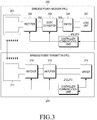
- FIG. 2 is a block diagram of a wireless power transmitter and a wireless power receiver according to an embodiment of the present invention.
- a wireless power transmitter 200 includes a power transmitting unit 211, a controller 212, and a communication unit 213.
- a wireless power receiver 250 may include a power receiving unit 251, a controller 252 and a communication unit 253.
- the power transmitting unit 211 supplies the power required by the wireless power transmitter 200, and may wirelessly supply the power to the wireless power receiver 250.
- the power transmitting unit 211 supplies power in the form of an Alternating Current (AC) waveform, or may supply power in the form of Direct Current (DC) waveform. In the latter case, the power transmitting unit 211 converts the DC waveform into an AC waveform using an inverter, and supplies the power in the form of an AC waveform.
- the power transmitting unit 211 may be implemented in the form of built-in battery, or may be implemented in the form of power receiving interface to receive power from the outside and supply the received power to the other components. It will be apparent to those of ordinary skill in the art that any means may replace the power transmitting unit 211 as long as it can supply power in the form of a predetermined AC waveform.
- the power transmitting unit 211 may provide AC waveforms to the wireless power receiver 250 in the form of electromagnetic waves.
- the power transmitting unit 211 may further include a resonance circuit, so the power transmitting unit 211 transmits or receives predetermined electromagnetic waves. If the power transmitting unit 211 is implemented with a resonance circuit, an inductance L of a loop coil in the resonance circuit may be subject to change. It will be apparent to those of ordinary skill in the art that any means may replace the power transmitting unit 211 as long as it can transmit and receive electromagnetic waves.
- the controller 212 controls the overall operation of the wireless power transmitter 200.
- the controller 212 may control the overall operation of the wireless power transmitter 200 using an algorithm, a program or an application, each of which is read from a storage (not shown) and required for the control.
- the controller 212 may be implemented in the form of a Central Processing Unit (CPU), a microprocessor, a minicomputer, and the like. A detailed operation of the controller 212 will be described in more detail below.
- the communication unit 213 performs communication with the wireless power receiver 250 using a predetermined communication scheme.
- the communication unit 213 may perform communication with the communication unit 253 of the wireless power receiver 250, using Near Field Communication (NFC), Zigbee, Infrared Data Association (IrDA), Visible Light Communication (VLC), Bluetooth, Bluetooth Low Energy (BLE), and the like.
- the communication unit 213 may employ a Carrier Sense Multiple Access with Collision Avoidance (CSMA/CA) algorithm.
- CSMA/CA Carrier Sense Multiple Access with Collision Avoidance
- the communication unit 213 transmits a signal for information about the wireless power transmitter 200.
- the communication unit 213 may unicast, multicast, or broadcast the signal.
- Table 1 below illustrates a data structure of a signal transmitted from the wireless power transmitter 200 according to an embodiment of the present invention.
- the wireless power transmitter 200 transmits a signal having the following frame at a preset cycle, and the signal may be called herein a 'Notice' signal.
- Table 1 fra me type pro tocol version seq uence number net work ID RX to Report(schedule mask) Res erved Nu mber of Rx Not ice 4 bit 1 Byte 1 Byte 1 Byte 5 bit 3 bit
- a 'frame type' field which is a field indicating a type of the signal, indicates that the signal is a 'Notice' signal.
- a 'protocol version' field which is a field indicating a protocol type of a communication scheme, may be allocated, for example, 4 bits.
- a 'sequence number' field which is a field indicating a sequence number of the signal, may be allocated, for example, 1 byte. The sequence number may increase one by one in response to, for example, a signal transmission/reception phase.
- a 'network ID' field which is a field indicating a network ID of the wireless power transmitter 200, may be allocated, for example, 1 byte.
- a 'Rx to Report(schedule mask)' field which is a field indicating the wireless power receivers that will make a report to the wireless power transmitter 200, may be allocated, for example, 1 byte.
- Table 2 illustrates the 'Rx to Report(schedule mask)' field according to an embodiment of the present invention.
- Table 2 Rx to Report(schedule mask) 1 Rx 2 Rx R x3 R x4 R x5 R x6 R x7 R x8 1 0 0 0 0 1 1 1
- Rx1 to Rx8 may correspond to first to eighth wireless power receivers.
- a 'Reserved' field which is a field reserved for future use, may be allocated, for example, 5 bits.
- a 'Number of Rx' field which is a field indicating the number of wireless power receivers around the wireless power transmitter 200, may be allocated, for example, 3 bits.
- the communication unit 213 receives power information from the wireless power receiver 250.
- the communication unit 213 transmits a charging function control signal for controlling the charging function of the wireless power receiver 250.
- the charging function control signal may be a control signal for enabling or disabling the charging function by controlling the power receiving unit 251 of the wireless power receiver 250.
- the power information may include information about insertion of a wired charging terminal, transition from a Stand Alone (SA) mode to a Non Stand Alone (NSA) mode, and release of error situations, all of which will be described below.
- SA Stand Alone
- NSA Non Stand Alone
- the communication unit 213 may receive not only the signal from the wireless power receiver 250, but also the signal from at least one other wireless power transmitter (not shown). For example, the communication unit 213 may receive the 'Notice' signal of the frame in Table 1 from another wireless power transmitter.
- the power transmitting unit 211 and the communication unit 213 are configured as different hardware structures in FIG. 2 , so the wireless power transmitter 200 seems to communicate in an out-band way, this is merely illustrative.
- the power transmitting unit 211 and the communication unit 213 may be implemented as a single hardware structure, so the wireless power transmitter 200 may perform communication in an in-band way.
- the wireless power transmitter 200 transmits and receives a variety of signals to/from the wireless power receiver 250. Accordingly, a process in which the wireless power receiver 250 joins the wireless power network managed by the wireless power transmitter 200 and a process in which the wireless power receiver 250 is charged through wireless power transmission/reception are performed, and a detailed description thereof will be given below.
- FIG. 3 is a detailed block diagram of a wireless power transmitter and a wireless power receiver according to an embodiment of the present invention.
- the wireless power transmitter (or Power Transmission Unit (PTU)) 200 includes the power transmitting unit 211, a controller/communication unit(or MCU & Out-of-band Signaling unit) 212/213, a driver 214, an amplifier 215, and a matcher 216.
- the wireless power receiver (or Power Reception Unit (PRU)) 250 includes the power receiving unit 251, a controller/communication unit(or MCU & Out-of-band Signaling unit) 252/253, a rectifier 254, a DC/DC converter 255, a switch 256, and a load unit 257.
- the driver 214 outputs DC power having a preset voltage value.
- the voltage value of the DC power output from the driver 214 is controlled by the controller/communication unit 212/213.
- a DC current output from the driver 214 is output to the amplifier 215.
- the amplifier 215 amplifies the DC current with a preset gain.
- the amplifier 215 converts the DC current into an AC current based on the signal received from the controller/communication unit 212/213. Accordingly, the amplifier 215 outputs an AC current.
- the matcher 216 performs impedance matching. For example, the matcher 216 adjusts the impedance seen from the matcher 216 to control the output power to have high efficiency and high power. The matcher 216 adjusts the impedance under controller of the controller/communication unit 212/213.
- the matcher 216 may include at least one of a coil and a capacitor.
- the controller/communication unit 212/213 may control a connection status to at least one of the coil and the capacitor, and performs impedance matching according thereto.
- the power transmitting unit 211 transmits the input AC power to the power receiving unit 251.
- Each of the power transmitting unit 211 and the power receiving unit 251 may be implemented with a resonance circuit having the same resonant frequency.
- the resonant frequency may be determined as 6.78MHz.
- the controller/communication unit 212/213 performs communication with the controller/communication unit 252/253 in the wireless power receiver 250, and may perform, for example, bi-directional communication at a frequency of 2.4GHz.
- the power receiving unit 251 receives charging power.
- the rectifier 254 rectifies the wireless power received at the power receiving unit 251 into DC power, and may be implemented in the form of, for example, a bridge diode.
- the DC/DC converter 255 converts the rectified power with a preset gain.
- the DC/DC converter 255 may convert the rectified power so that its output terminal 259 may have a voltage of 5V.
- the minimum value and maximum value of a voltage applicable to a front end 258 of the DC/DC converter 255 may be set in advance.
- the switch 256 connects the DC/DC converter 255 to the load unit 257.
- the switch 256 keeps an ON/OFF status under control of the controller 252. If the switch 256 is in an ON status, the load unit 257 stores the converted power received from the DC/DC converter 255.
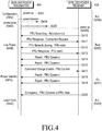
- FIG. 4 is a flow diagram illustrating operations of a wireless power transmitter and a wireless power receiver according to an embodiment of the present invention.
- a wireless power transmitter (or PTU) 400 is powered up in step S401.
- the wireless power transmitter 400 configures (or sets) the environment in step S402.
- the wireless power transmitter 400 enters a power save mode in step S403.
- the wireless power transmitter 400 may apply different detection-purpose power beacons at their own cycles, and a detailed description thereof will be given with reference to FIG. 6 .
- the wireless power transmitter 400 may apply detection-purpose power beacons 404 and 405, and the detection-purpose power beacons 404 and 405 may be different from each other in magnitude of a power value.
- All or some of the detection-purpose power beacons 404 and 405 may have the power that can drive a communication unit of a wireless power receiver (or PRU) 450.
- the wireless power receiver 450 performs communication with the wireless power transmitter 400 by driving its communication unit by means of all or some of the detection-purpose power beacons 404 and 405.
- the above status is referred to as a null status S406.
- the wireless power transmitter 400 may detect a change in load, which is caused by the arrangement of the wireless power receiver 450.
- the wireless power transmitter 400 enters a low power mode in step S408.
- the low power mode will be described in detail with reference to FIG. 6 .
- the wireless power receiver 450 drives its communication unit based on the power received from the wireless power transmitter 400 in step S409.
- the wireless power receiver 450 transmits a PTU searching signal to the wireless power transmitter 400 in step S410.
- the wireless power receiver 450 transmits the PTU searching signal as an Advertisement signal that is based on Bluetooth Low Energy (BLE).
- BLE Bluetooth Low Energy
- the wireless power receiver 450 may periodically transmit the PTU searching signal and receive a response signal from the wireless power transmitter 400, or may transmit the PTU searching signal until a preset time has arrived.
- the wireless power transmitter 400 Upon receiving the PTU searching signal from the wireless power receiver 450, the wireless power transmitter 400 transmits a PRU Response signal in step S411.
- the response signal may be used to form a connection between the wireless power transmitter 400 and the wireless power receiver 450.
- the wireless power receiver 450 transmits a PRU static signal in step S412.
- the PRU static signal may be a signal indicating a status of the wireless power receiver 450, and may be used to request joining the wireless power network managed by the wireless power transmitter 400.
- the wireless power transmitter 400 transmits a PTU static signal in step S413.
- the PTU static signal transmitted by the wireless power transmitter 400 may be a signal indicating the capability of the wireless power transmitter 400.
- the wireless power receiver 450 periodically transmits a PRU Dynamic signal in steps S414 and S415.
- the PRU Dynamic signal may include information about at least one parameter measured in the wireless power receiver 450.
- the PRU Dynamic signal may include information about a voltage at a rear end of a rectifier in the wireless power receiver 450.
- the above status of the wireless power receiver 450 is referred to as a boot status S407.
- the wireless power transmitter 400 enters a power transfer mode in step S416, and the wireless power transmitter 400 transmits a PRU command signal, which is a command signal for enabling the wireless power receiver 450 to perform charging, in step S417. In the power transfer mode, the wireless power transmitter 400 transmits charging power.
- the PRU command signal transmitted by the wireless power transmitter 400 may include information for enabling/disabling the charging of the wireless power receiver 450, and information for permitting the charging of the wireless power receiver 450.
- the PRU command signal may be transmitted if the wireless power transmitter 400 commands to change the status of the wireless power receiver 450, or may be transmitted at a preset cycle of, for example, 250ms.
- the wireless power receiver 450 changes the configuration according to the PRU command signal, and transmits a PRU Dynamic signal for reporting the status of the wireless power receiver 450 in steps S418 and S419.
- the PRU Dynamic signal transmitted by the wireless power receiver 450 may include information about at least one of voltage, current, PRU status, and temperature. The above status of the wireless power receiver 450 is referred to as an ON status S421.
- the PRU Dynamic signal may have a data structure as illustrated in Table 3.
- Table 3 Field octets descripti on use units optional fields 1 defines which optional fields are populated mandator y Vrect 2 voltage at diode output mandator y mV Irect 2 current at diode output mandator y mA Vout 2 voltage at charge/battery port optional mV lout 2 current at charge/battery port optional mA temperat ure 1 temperat ure of PRU optional Deg C from -40C Vrect min dyn 2 Vrect low limit(dynamic value) optional mV Vrect set dyn 2 desired Vrect (dynamic value) optional mV Vrect high dyn 2 Vrect high limit (dynamic value) optional mV PRU alert 1 warnings mandator y Bit field RFU(Res erved for Future Use) 3 undefine d
- the PRU Dynamic signal may include at least one of information about optional fields, information about a voltage at a rear end of a rectifier of the wireless power receiver Vrect, information about a current at the rear end of the rectifier of the wireless power receiver Irect, information about a voltage at a rear end of a DC/DC converter of the wireless power receiver Vout, information about a current at the rear end of the DC/DC converter of the wireless power receiver lout, temperature information, information about the minimum voltage at the rear end of the rectifier of the wireless power receiver Vrect min dyn, information about the optimal voltage at the rear end of the rectifier of the wireless power receiver Vrect set dyn, information about the maximum voltage at the rear end of the rectifier of the wireless power receiver Vrect high dyn, and alert information PRU alert.
- the alert information('PRU alert') may be formed in a data structure as illustrated in Table 4.
- the alert information may include, as illustrated in Table 4, 'over voltage' information, 'over current' information, 'over temperature' information, 'charge complete' information, 'TA detect' information (for detecting insertion of a wired charging terminal (or Travel Adapter (TA) terminal)), 'transition' information (for transition between the SA mode and the NSA mode), 'restart request' information and the like.
- the wireless power receiver 450 performs charging by receiving a PRU command signal. For example, if the wireless power transmitter 400 has power enough to charge the wireless power receiver 450, the wireless power transmitter 400 transmits a PRU command signal for enabling the charging.
- the PRU command signal may be transmitted every time the charging status is changed.
- the PRU command signal may be transmitted every 250ms for example, or may be transmitted when there is a change in parameters.
- the PRU command signal may be set such that the PRU command signal should be transmitted within a preset threshold time (e.g., one second) even though there is no change in a parameter.
- the wireless power receiver 450 may detect occurrence of an error.
- the wireless power receiver 450 transmits an alert signal to the wireless power transmitter 400 in step S420.
- the alert signal may be transmitted as a PRU Dynamic signal, or may be transmitted as a PRU alert signal.
- the wireless power receiver 450 may reflect the error situations in the PRU alert field in Table 3, and transmit the results to the wireless power transmitter 400.
- the wireless power receiver 450 may transmit a single PRU alert signal indicating the error situations to the wireless power transmitter 400.
- the wireless power transmitter 400 Upon receiving the alert signal, the wireless power transmitter 400 enters a latch fault mode in step S422.
- the wireless power receiver 450 enters a null status in step S423.
- FIG. 5 is a flowchart illustrating operations of a wireless power transmitter and a wireless power receiver according to another embodiment of the present invention. The control method in FIG. 5 will be described in more detail with reference to FIG. 6.
- FIG. 6 is a time axis graph for power applied by a wireless power transmitter in an embodiment of FIG. 5 .
- a wireless power transmitter starts its driving in step S501.
- the wireless power transmitter resets an initial configuration (or initial settings) in step S503.
- the wireless power transmitter enters the power save mode in step S505.
- the power save mode may correspond to an interval in which the wireless power transmitter applies powers having different power levels to its power transmitting unit.
- the power save mode may correspond to an interval in which the wireless power transmitter applies second detection powers 601 and 602 and third detection powers 611, 612, 613, 614 and 615 in FIG. 6 , to the power transmitting unit.
- the wireless power transmitter may periodically apply the second powers 601 and 602 at a second cycle, and when applying the second powers 601 and 602, the wireless power transmitter may apply the second powers 601 and 602 for a second period.
- the wireless power transmitter may periodically apply the third powers 611, 612, 613, 614 and 615 at a third cycle, and when applying the third powers 611, 612, 613, 614 and 615, the wireless power transmitter may apply the third powers 611, 612, 613, 614 and 615 for a third period.
- the power value for each of the third powers 611, 612, 613, 614 and 615 may be different from, or equal to, each other.
- the wireless power transmitter may output the third power 612 having the same power level.
- the wireless power transmitter may output the third power having the same power level, the third power may have a power level capable of detecting the lowest-power wireless power receiver (e.g., a wireless power receiver in category 1, with category 1 denoting the lowest-power wireless power receiver).
- the wireless power transmitter may output the third power 612 having a different power level.
- each of the third powers may correspond to a power level capable of detecting wireless power receivers in categories 1 to 5.
- the third power 611 may have a power level capable of detecting a wireless power receiver in category 1
- the third power 612 may have a power level capable of detecting a wireless power receiver in category 3
- the third power 613 may have a power level capable of detecting a wireless power receiver in category 5.
- category 1 refers to the lowest-power wireless power receiver
- category 5 refers to the highest-power wireless power receiver.
- the second powers 601 and 602 may be the power that can drive the wireless power receiver. More specifically, the second powers 601 and 602 may have a power level capable of driving a controller and a communication unit in the wireless power receiver.
- the wireless power transmitter applies the second powers 601 and 602 and the third powers 611, 612, 613, 614 and 615 to the power receiving unit at a second cycle and a third cycle, respectively. If the wireless power receiver is placed on the wireless power transmitter, the impedance seen at one point of the wireless power transmitter may be changed.
- the wireless power transmitter detects the change in impedance while the second powers 601 and 602 and the third powers 611, 612, 613, 614 and 615 are applied. For example, the wireless power transmitter may detect a change in impedance while applying the third power 615. Accordingly, the wireless power transmitter detects an object in step S507. If no object is detected in step S507, the wireless power transmitter remains in the power save mode, in which the wireless power transmitter periodically applies different powers, in step S505.
- the low power mode is a mode in which the wireless power transmitter applies driving power having a power level capable of driving a controller and a communication unit in the wireless power receiver.
- the wireless power transmitter applies driving power 620 to its power transmitting unit.
- the wireless power receiver drives its controller and communication unit by receiving the driving power 620.
- the wireless power receiver performs communication with the wireless power transmitter based on a predetermined scheme using the driving power 620.
- the wireless power receiver may transmit/receive the data required for authentication, and based thereon, the wireless power receiver joins the wireless power network managed by the wireless power transmitter.
- the wireless power transmitter determines in step S511 whether the object placed thereon is a foreign object. For example, upon failure to receive a response from the object for a preset time, the wireless power transmitter determines the object to be a foreign object. If the wireless power transmitter determines that the object is not a foreign object in step S511, the object which is a wireless power receiver, joins the wireless power network managed by the wireless power transmitter in step S519.
- the wireless power transmitter enters the latch fault mode in step S513.
- the wireless power transmitter may periodically apply first powers 631 to 634 in FIG. 6 at a first cycle.
- the wireless power transmitter may detect a change in impedance while applying the first powers. For example, if the foreign object is removed, the wireless power transmitter may detect a change in impedance, and the wireless power transmitter determines that the foreign object is removed. If the foreign object is not removed, the wireless power transmitter may not detect a change in impedance, and the wireless power transmitter determines that the foreign object is not removed.
- the wireless power transmitter may output at least one of lamp light and alert tone, notifying the user that the current status of the wireless power transmitter is an error status. Accordingly, the wireless power transmitter may include an output unit for outputting at least one of the lamp light and the alert tone.
- the wireless power transmitter If it is determined that the foreign object has not been removed in step S515, the wireless power transmitter remains in the latch fault mode in step S513. On the other hand, if it is determined that the foreign object has been removed in step S515, the wireless power transmitter re-enters the power save mode in step S517. For example, the wireless power transmitter applies second powers 651 and 652 and third powers 661 to 665 in FIG. 6 .
- the wireless power transmitter enters the latch fault mode, if a foreign object other than the wireless power receiver is placed thereon.
- the wireless power transmitter may determine whether the foreign object is removed, depending on the change in impedance, which is caused by the power applied in the latch fault mode.
- a latch fault mode entry condition in the embodiments of FIGs. 5 and 6 is the arrangement of the foreign object.
- the wireless power transmitter may have a variety of latch fault mode entry conditions in addition to the arrangement of the foreign object. For example, the wireless power transmitter may enter the latch fault mode if the wireless power transmitter is cross-connected to the wireless power receiver placed thereon.
- the wireless power transmitter may set, as a latch fault mode entry condition, cross connection, which occurs if a wireless power receiver placed on another wireless power transmitter joins the wireless power network managed by the wireless power transmitter.
- cross connection may set, as a latch fault mode entry condition, cross connection, which occurs if a wireless power receiver placed on another wireless power transmitter joins the wireless power network managed by the wireless power transmitter.
- FIG. 7 to describe an operation of a wireless power transmitter, which is performed when an error including cross connection occurs.
- FIG. 7 is a flowchart illustrating a control method of a wireless power transmitter according to an embodiment of the present invention. The control method in FIG. 7 will be described in more detail with reference to FIG. 8.
- FIG. 8 is a time axis graph for power applied by a wireless power transmitter in an embodiment of FIG. 7 .
- a wireless power transmitter starts its driving in step S701.
- the wireless power transmitter resets an initial configuration (or initial settings) in step S703.
- the wireless power transmitter enters the power save mode in step S705.
- the power save mode may correspond to an interval in which the wireless power transmitter applies powers having different power levels to its power transmitting unit.
- the power save mode may correspond to an interval in which the wireless power transmitter applies second powers 801 and 802 and third powers 811, 812, 813, 814 and 815 in FIG. 8 , to the power transmitting unit.
- the wireless power transmitter may periodically apply the second powers 801 and 802 at a second cycle, and when applying the second powers 801 and 802, the wireless power transmitter may apply the second powers 801 and 802 for a second period.
- the wireless power transmitter may periodically apply the third powers 811, 812, 813, 814 and 815 at a third cycle, and when applying the third powers 811, 812, 813, 814 and 815, the wireless power transmitter may apply the third powers 811, 812, 813, 814 and 815 for a third period.
- the power value for each of the third powers 811, 812, 813, 814 and 815 may be different from, or equal to, each other.
- the second powers 801 and 802 may be the power that can drive the wireless power receiver. More specifically, the second powers 801 and 802 may have a power level capable of driving a controller and a communication unit in the wireless power receiver.
- the wireless power transmitter applies the second powers 801 and 802 and the third powers 811, 812, 813, 814 and 815 to the power receiving unit at a second cycle and a third cycle, respectively. If the wireless power receiver is placed on the wireless power transmitter, the impedance seen at one point of the wireless power transmitter may be changed.
- the wireless power transmitter may detect the change in impedance while the second powers 801 and 802 and the third powers 811, 812, 813, 814 and 815 are applied. For example, the wireless power transmitter may detect a change in impedance while applying the third power 815. Accordingly, the wireless power transmitter detects an object in step S707. If no object is detected in step S707, the wireless power transmitter remains in the power save mode, in which the wireless power transmitter periodically applies different powers, in step S705.
- the wireless power transmitter enters the low power mode in step S709.
- the low power mode is a mode in which the wireless power transmitter applies driving power having a power level capable of driving a controller and a communication unit in the wireless power receiver.
- the wireless power transmitter applies driving power 820 to its power transmitting unit.
- the wireless power receiver drives its controller and communication unit by receiving the driving power 820.
- the wireless power receiver performs communication with the wireless power transmitter based on a predetermined scheme using the driving power 820.
- the wireless power receiver may transmit/receive the data required for authentication, and based thereon, the wireless power receiver may join the wireless power network managed by the wireless power transmitter.
- the wireless power transmitter enters the power transfer mode, in which the wireless power transmitter transmits charging power, in step S711.
- the wireless power transmitter may apply charging power 821 as in FIG. 8 , and the charging power may be transmitted to the wireless power receiver.
- the wireless power transmitter determines in step S713 whether an error occurs.
- the error may include a foreign object being placed on a wireless power transmitter, cross connection, over voltage, over current, over temperature, and the like.
- the wireless power transmitter may include a sensing unit capable of measuring the over voltage, over current, over temperature, and the like.
- the wireless power transmitter may measure a power or a current at a reference point, and if the measured voltage or current exceeds a threshold, the wireless power transmitter determines that over-voltage or over-current conditions are met.
- the wireless power transmitter may include a temperature sensing means, and the temperature sensing means may measure the temperature at a reference point of the wireless power transmitter. If the temperature at the reference point exceeds a threshold, the wireless power transmitter determines that the over-temperature conditions are met.
- the error is not limited thereto, and it will be apparent to those of ordinary skill in the art that the wireless power transmitter may operate in a similar process, even upon occurrence of a foreign object being placed on the wireless power transmitter, cross connection, over voltage, over current, over temperature, and the like.
- step S713 the wireless power transmitter remains in the power transfer mode in step S711.
- the wireless power transmitter enters the latch fault mode in step S715.
- the wireless power transmitter may apply first powers 831 to 835 as in FIG. 8 .
- the wireless power transmitter may output an error indication including at least one of lamp light and alert tone during the latch fault mode. If it is determined in step S717 that a foreign object or a wireless power receiver has not been removed, the wireless power transmitter remains in the latch fault mode in step S715. On the contrary, if it is determined in step S717 that a foreign object or a wireless power receiver has been removed, the wireless power transmitter re-enters the power save mode in step S719. For example, the wireless power transmitter may apply second detection powers 851 and 852 and third detection powers 861 to 865 in FIG. 8 .
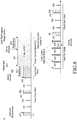
- FIG. 9 is a flowchart illustrating a control method of a wireless power transmitter according to an embodiment of the present invention. The control method in FIG. 9 will be described in more detail with reference to FIG. 10.
- FIG. 10 is a time axis graph for power applied by a wireless power transmitter in an embodiment of FIG. 9 .
- a wireless power transmitter transmits charging power to a first wireless power receiver in step S901.
- the wireless power transmitter may cause a second wireless power receiver to join the wireless power network in step S903.
- the wireless power transmitter also transmits charging power to the second wireless power receiver in step S905. More specifically, the wireless power transmitter may apply, to the power receiving units, a sum of the charging power required by the first wireless power receiver and the charging power required by the second wireless power receiver.
- steps S901 to S905 is illustrated in FIG. 10 .
- the wireless power transmitter remains in the power save mode in which the wireless power transmitter applies second powers 1001 and 1002 and third powers 1011 to 1015.
- the wireless power transmitter upon detecting the first wireless power receiver, the wireless power transmitter enters the low power mode in which the wireless power transmitter keeps detection power 1020.
- the wireless power transmitter enters the power transfer mode in which the wireless power transmitter applies first charging power 1030.
- the wireless power transmitter detects the second wireless power receiver, and causes the second wireless power receiver to join the wireless power network.
- the wireless power transmitter may apply second charging power 1040 that has the total power level corresponding to a power level required by the first wireless power receiver and a power level required by the second wireless power receiver.
- the wireless power transmitter detects whether an error has occurred in step S907 while transmitting the charging power to both of the first and second wireless power receivers in step S905.
- the error may include arrangement of a foreign object, cross connection, over voltage, over current, over temperature, and the like. If no error occurs in step S907, the wireless power transmitter continues to apply the second charging power 1040.
- the wireless power transmitter enters the latch fault mode in step S909.
- the wireless power transmitter may apply first powers 1051 to 1055 in FIG. 10 at a first cycle.
- the wireless power transmitter determines in operation S911 whether both of the first wireless power receiver and the second wireless power receiver have been removed.
- the wireless power transmitter may detect a change in impedance while applying the first powers 1051 to 1055. Based on whether the impedance returns to its initial value, the wireless power transmitter may determine whether both of the first wireless power receiver and the second wireless power receiver are removed.
- the wireless power transmitter enters the power save mode in step S913.
- the wireless power transmitter may apply second powers 1061 and 1062 and third powers 1071 to 1075 in FIG. 10 at a second cycle and a third cycle, respectively.
- the wireless power transmitter may easily determine whether a wireless power receiver or a foreign object is removed, upon occurrence of an error.
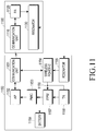
- FIG. 11 is a block diagram of a wireless power transmitter and a wireless power receiver according to an embodiment of the present invention.
- a wireless power transmitter 1100 includes a communication unit 1110, a Power Amplifier (PA) 1120 and a resonator 1130.
- a wireless power receiver 1150 includes a communication unit 1151, an Application Processor (AP) 1152, a Power Management Integrated Circuit (PMIC) 1153, a wireless power integrated circuit 1154, a resonator 1155, an Interface Power Management IC (IFPM) 1157, a wired charging adapter (also known as a Travel Adapter (TA)) 1158, and a battery 1159.
- AP Application Processor
- PMIC Power Management Integrated Circuit
- IFPM Interface Power Management IC
- TA Travel Adapter
- the communication unit 1110 performs communication with the communication unit 1151 based on a predetermined scheme (e.g., BLE scheme).
- a predetermined scheme e.g., BLE scheme
- the communication unit 1151 in the wireless power receiver 1150 may transmit a PRU Dynamic signal having the data structure of Table 3 to the communication unit 1110 in the wireless power transmitter 1100.
- the PRU Dynamic signal may include at least one of voltage information, current information, temperature information and alert information of the wireless power receiver 1150.
- an output power value from the power amplifier 1120 may be adjusted. For example, if over voltage, over current or over temperature is applied to the wireless power receiver 1150, a power value output from the power amplifier 1120 may be reduced. In addition, if the voltage or current of the wireless power receiver 1150 is less than a preset value, the power value output from the power amplifier 1120 may increase.
- the charging power from the resonator 1130 is wirelessly transmitted to the resonator 1155.
- the wireless power integrated circuit 1154 rectifies the charging power received from the resonator 1155, and perform DC/DC conversion on the rectified charging power.
- the wireless power integrated circuit 1154 may drive the communication unit 1151 with the converted power, or may charge the battery 1159 with the converted power.
- a wired charging terminal may be inserted in the wired charging adapter (TA) 1158.
- TA wired charging adapter
- a wired charging terminal such as a 30-pin connector, a Universal Serial Bus (USB) connector or the like may be inserted.
- the wired charging adapter 1158 may receive power supplied from an external power source, and charge the battery 1159 with the received power.
- the interface power management integrated circuit 1157 processes the power received from the wired charging terminal, and outputs the processed power to the battery 1159 and the power management integrated circuit 1153.
- the power management integrated circuit 1153 manages the power received wirelessly or by wires, and the power applied to each of the components of the wireless power receiver 1150.
- the AP 1152 receives power information from the power management integrated circuit 1153, and controls the communication unit 1151 to transmit a PRU Dynamic signal for reporting the received power information.
- a node 1156 connected to the wireless power integrated circuit 1154 may also be connected to the wired charging adapter 1158. If a wired charging connector (or a wired charging terminal) is inserted in the wired charging adapter 1158, a preset voltage (e.g., 5V) may be applied to the node 1156.
- the wireless power integrated circuit 1154 monitors a voltage applied to the node 1156, to determine whether the wired charging adapter 1158 is inserted.
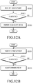
- FIG. 12A is a flowchart illustrating a control method of a wireless power receiver according to an embodiment of the present invention.
- the wireless power receiver 1150 wirelessly receives charging power from the wireless power transmitter 1100 in step S1201.
- the wireless power receiver 1150 determines in step S1203 whether a wired charging terminal is inserted in a wired charging adapter (TA).
- TA wired charging adapter
- the wireless power receiver 1150 may determine whether the wired charging terminal is inserted in the wired charging adapter, by determining whether a voltage applied to a rear end of the wired charging adapter corresponds to a preset voltage value.
- the wireless power receiver 1150 transmits a signal indicating the insertion of the wired charging terminal, to the wireless power transmitter 1100 in step S1205.
- the wireless power receiver 1150 may transmit, to the wireless power transmitter 1100, a PRU Dynamic signal indicating TA detect (3) in a PRU alert field in Table 4.
- the wireless power receiver 1150 transmits a signal indicating the insertion of the wired charging terminal to the wireless power transmitter 1100 as a signal different from the PRU Dynamic signal.
- the wireless power receiver 1150 stops wireless charging by releasing the connection to the resonator 1155.
- FIG. 12B is a flowchart illustrating a control method of a wireless power transmitter according to an embodiment of the present invention.
- the wireless power transmitter 1100 wirelessly transmits charging power to the wireless power receiver 1150 in step S1211.
- the wireless power transmitter 1100 receives a signal indicating the insertion of the wired charging terminal from the wireless power receiver 1150 in step S1213. If the signal indicating the insertion of the wired charging terminal is received in step S1213, the wireless power transmitter 1100 adjusts the charging power in step S1215. For example, the wireless power transmitter 1100 may stop the transmission of the charging power by adjusting the charging power to zero (0).
- the wireless power transmitter 1100 stops the wireless charging, preventing overpower from being applied.
- FIG. 13 is a flowchart illustrating operations of a wireless power transmitter and a wireless power receiver according to an embodiment of the present invention.
- the wireless power transmitter 1100 transmits a charging start command signal to the wireless power receiver 1150 in step S1301.
- the wireless power receiver 1150 performs wireless charging by turning on a load switch in step S1302.
- the wireless power receiver 1150 transmits a PRU Dynamic signal in step S1303, and the wireless power transmitter 1100 receives and analyzes the PRU Dynamic signal in step S1304.
- the wireless power transmitter 1100 may determine information about voltage, current and temperature of the wireless power receiver 1150, or wireless charging environment change information such as information about insertion of the wired charging terminal.
- a user may insert the wired charging terminal in the wireless power receiver 1150, and the wireless power receiver 1150 detects the insertion in step S1305.
- the wireless power receiver 1150 determines in step S1306 whether wired or wireless power is received. If neither of the wired nor wireless power is received in step S1306, the wireless power receiver 1150 enters the power save mode in step S1307. However, if it is determined that both of wired charging and wireless charging are performed in step S1306, the IFPM 1157 in the wireless power receiver 1150 stops the wireless charging by releasing the connection from the resonator 1155 in step S1308.
- the wireless power receiver 1150 outputs information indicating the detection of the insertion of the wired charging terminal to the communication unit 1151 in step S1309, and the communication unit 1151 transmits a signal indicating the detection of the insertion of the wired charging terminal to the wireless power transmitter 1100 in step S1310.
- the wireless power transmitter 1100 adjusts the charging power in step S1311. For example, the wireless power transmitter 1100 may stop the wireless charging by adjusting the charging power to zero (0).
- the wireless power transmitter 1100 instructs 'no power reception' in step S1312, and the wireless power transmitter 1100 transmits a load switch OFF signal to the wireless power receiver 1150 in step S1313.
- the wireless power receiver 1150 may turns off the load switch in step S1314.
- the wireless power receiver 1150 may periodically transmit a PRU Dynamic signal in step S1315.
- the wireless power transmitter 1100 receives and analyzes the PRU Dynamic signal in step S1316.
- the wireless power receiver 1150 detects the release (or plug-out) of the wired charging terminal (TA) in step S1317.
- the wireless power receiver 1150 may detect the release of the wired charging terminal by detecting a change in voltage applied to a rear end of the wired charging adapter 1158.
- the wireless power receiver 1150 transmits a signal indicating the detection of the release of the wired charging terminal to the wireless power transmitter 1100 in step S1318.
- the wireless power receiver 1150 may transmit the signal indicating the detection of the release of the wired charging terminal as a PRU Dynamic signal or a single signal.
- the wireless power transmitter 1100 analyzes the PRU Dynamic signal or the single signal and determines that the insertion of the wired charging terminal into the wireless power receiver 1150 is released, in step S1319.
- the wireless power transmitter 1100 transmits a load switch ON signal to the wireless power receiver 1150 in step S1320, and upon receiving the load switch ON signal, the wireless power receiver 1150 turns on the load switch in step S1321.
- the wireless power transmitter 1100 performs wireless charging by re-adjusting the charging power, and the wireless power receiver 1150 performs wireless charging by turning on the load switch.
- the wireless power transmitter 1100 may determine whether the wired charging terminal is inserted in, or drawn out from the wireless power receiver 1150. The wireless power transmitter 1100 may adjust the charging power depending on whether the wired charging terminal is inserted in, or drawn out from the wireless power receiver 1150, thereby preventing the waste of power and preventing overpower from being applied to the wireless power receiver 1150.
- FIG. 14 is a block diagram of a communication unit and peripheral components of a wireless power receiver according to an embodiment of the present invention.
- the communication unit 1151 of the wireless power receiver 1150 includes a Random Access Memory (RAM) 1161, and a Read Only Memory (ROM) 1162.
- the communication unit 1151 performs communication with the wireless power transmitter 1100 based on a predetermined scheme (e.g., BLE scheme). Accordingly, a stack (e.g., BLE stack) of the predetermined communication scheme needs to be loaded in the RAM 1161 of the communication unit 1151.
- the communication unit 1151 may receive a BLE stack from the AP 1152, and load the BLE stack in the RAM 1161.
- NSA Non-Stand Alone
- the wireless power receiver 1150 is placed on the wireless power transmitter 1100 after the battery 1159 is discharged. In this case, the wireless power receiver 1150 cannot drive the AP 1152 since the battery 1159 is discharged.
- the wireless power receiver 1150 drives the communication unit 1151 of the wireless power receiver 1150 by receiving detection-purpose power beacons.
- the communication unit 1151 may not receive the stack of the predetermined communication scheme from the AP 1152.
- the communication unit 1151 may store the stack of the predetermined communication scheme in the ROM 1162, and performs communication with the wireless power transmitter 1100 using the stack of the predetermined communication scheme, which is stored in the ROM 1162.
- SA Stand Alone
- FIG. 15A is a flowchart illustrating a control method of a wireless power receiver according to an embodiment of the present invention.
- the wireless power receiver 1150 is powered off due to the discharge of the battery 1159 in step S1501.
- the wireless power receiver 1150 receives first power capable of driving the communication unit 1151, from the wireless power transmitter 1100 in step S1503, and drives the communication unit 1151 using the received power.
- the wireless power receiver 1150 enters the SA mode, and loads a BLE stack for example, from the ROM in step S1505.
- the communication unit 1151 of the wireless power receiver 1150 performs communication with the wireless power transmitter 1100 using the loaded BLE stack in step S1507.
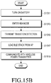
- FIG. 15B is a flowchart illustrating a control method of a wireless power receiver according to an embodiment of the present invention.
- the wireless power receiver 1150 performs wireless charging while operating in the SA mode. Based on the wireless charging, the wireless power receiver 1150 turns on the battery 1159 and the AP 1152 in step S1511. The wireless power receiver 1150 transitions from the SA mode to the NSA mode in step S1513. The wireless power receiver 1150 transmits a mode transition detection signal to the wireless power transmitter 1100 in step S1515. The wireless power receiver 1150 loads a BLE stack from the AP 1152 in step S1517, and resumes the communication with the wireless power transmitter 1100 in step S1519.
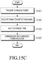
- FIG. 15C is a flowchart illustrating a control method of a wireless power transmitter according to an embodiment of the present invention.
- the wireless power transmitter 1100 transmits charging power to the wireless power receiver 1150 in step S1521.
- the wireless power transmitter 1100 receives a detection signal indicating transition from the SA mode to the NSA mode from the wireless power receiver 1150 in step S1523.
- the wireless power transmitter 1100 waits for a preset waiting time in step S1525.
- the wireless power transmitter 1100 may be set to exclude the wireless power receiver 1150 from the wireless power network if no signal is received from the wireless power receiver 1150 for one second.
- the wireless power transmitter 1100 does not exclude the wireless power receiver 1150 from the wireless power network even if no signal is received from the wireless power receiver 1150 for a preset waiting time.
- the wireless power transmitter 1100 resumes communication with the wireless power receiver 1150 in step S1527.
- the wireless power transmitter 1100 does not exclude the wireless power receiver 1150 from the wireless power network, even if no signal is received from the wireless power receiver 1150 for a preset waiting time. As a result, it is possible to prevent an error from unintentionally occurring due to the mode transition of the wireless power receiver.
- the wireless power transmitter 1100 may determine changes in wireless power transmission environment, such as the mode transition, and does not exclude the wireless power receiver 1150 from the wireless power network in response to the changes in wireless power transmission environment.
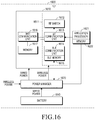
- FIG. 16 is a block diagram of a wireless power receiver according to an embodiment of the present invention.
- an application processor 1621 of a wireless power receiver 1600 includes a memory 1622.
- a communication unit 1611 also individually includes a BLE memory 1615.
- the memory 1622 of the application processor 1621 may store a public address for communication of the wireless power receiver 1600.
- the BLE memory 1615 may store a stack (e.g., BLE stack) for communication. More specifically, the BLE memory 1615 may also store the public address.
- the wireless power receiver 1600 may use addresses defined in Table 5 below, in each of the SA mode and the NSA mode.
- Table 5 Address in SA mode Address in NSA mode Random address Random address same as that in SA mode Random address Public address Public address First random address Second random address
- the wireless power receiver 1600 performs communication with the wireless power transmitter 1100 using a random address in the SA mode.
- the random address may be generated by the wireless power receiver 1600.
- the wireless power receiver 1600 transmits a mode transition detection signal to the wireless power transmitter 1100.
- the wireless power receiver 1600 may store the random address it has used in the SA mode, while transmitting the mode transition detection signal.
- the wireless power transmitter 1100 receives the mode transition detection signal, and stores the random address it has used in the SA mode.
- the wireless power receiver 1600 transitions to the NSA mode, and may use the same random address it has used in the SA mode, even in the NSA mode.
- the wireless power transmitter 1100 may also use the same random address it has used in the SA mode. Accordingly, the wireless power transmitter 1100 and the wireless power receiver 1600 perform communication using the random address they have used in the SA mode, even in the NSA mode.
- the wireless power transmitter 1100 keeps applying the charging power, and does not determine the wireless power receiver 1600 to be a foreign object even if no signal is received from the wireless power receiver 1600 for a preset time.
- the wireless power receiver 1600 performs communication with the wireless power transmitter 1100 using a random address in the SA mode.
- the wireless power receiver 1600 When transitioning from the SA mode to the NSA mode, the wireless power receiver 1600 obtains a public address from the application processor 1621 and stores the public address in the RAM The wireless power receiver 1600 transmits a mode transition detection signal to the wireless power transmitter 1100.
- the mode transition detection signal may include public address information.
- the wireless power transmitter 1100 checks information about the public address to be used in the NSA mode, by analyzing the received mode transition detection signal.
- the wireless power receiver 1600 performs mode transition from the SA mode to the NSA mode.
- the wireless power receiver 1600 performs communication with the wireless power transmitter 1100 using the public address.
- the wireless power transmitter 1100 may also perform communication with the wireless power receiver 1600 using the public address obtained from the mode transition detection signal.
- the wireless power transmitter 1100 keeps applying the charging power, and does not determine the wireless power receiver 1600 to be a foreign object even if no signal is received from the wireless power receiver 1600 for a preset time.
- the wireless power receiver 1600 may store in advance the same public address as that of the application processor 1621 in the ROM of the communication unit 1611. Accordingly, the wireless power receiver 1600 performs communication with the wireless power transmitter 1100 using the public address even in the SA mode. The wireless power receiver 1600 transmits a mode transition detection signal to the wireless power transmitter 1100 before the mode transition.
- the wireless power transmitter 1100 stores the public address of the wireless power receiver 1600. In addition, the wireless power transmitter 1100 receives the mode transition detection signal, and uses the stored public address when resuming the communication in the NSA mode. Upon transition of the mode, the wireless power transmitter 1100 keeps applying the charging power, and does not determine the wireless power receiver 1600 to be a foreign object even if no signal is received from the wireless power receiver 1600 for a preset time.
- the wireless power receiver 1600 generates a first random address, and performs communication with the wireless power transmitter 1100 using the generated first random address.
- the wireless power receiver 1600 transitions from the SA mode to the NSA mode.
- the wireless power receiver 1600 transmits a mode transition detection signal to the wireless power transmitter 1100.
- the wireless power transmitter 1100 Upon transition of the mode, the wireless power transmitter 1100 keeps applying the charging power, and does not determine the wireless power receiver 1600 to be a foreign object even if no signal is received from the wireless power receiver 1600 for a preset time.
- the wireless power receiver 1600 generates a second random address in the NSA mode.
- the wireless power receiver 1600 may re-perform the boot operation (step S407) in FIG. 4 , using the second random address. More specifically, the wireless power receiver 1600 may perform the process of transmitting a PTU searching signal (step S410), receiving PRU response signal (step S411), transmitting PRU static signal (step S412), and receiving a PTU static signal (step S413), by using the second random address.
- various embodiments of the present invention may provide a wireless power receiver capable of performing communication with a wireless power transmitter even during discharge of its battery, and a control method thereof.
- various embodiments of the present invention may provide a wireless power transmitter for performing communication in response to the battery discharge, and a control method thereof.
- the wireless power transmitter and the wireless power receiver may stably maintain communication even in a mode transition process, so communication for wireless charging may be stably performed.
Landscapes
- Engineering & Computer Science (AREA)
- Computer Networks & Wireless Communication (AREA)
- Power Engineering (AREA)
- Signal Processing (AREA)
- Microelectronics & Electronic Packaging (AREA)
- Manufacturing & Machinery (AREA)
- Chemical & Material Sciences (AREA)
- Chemical Kinetics & Catalysis (AREA)
- Electrochemistry (AREA)
- General Chemical & Material Sciences (AREA)
- Charge And Discharge Circuits For Batteries Or The Like (AREA)
Applications Claiming Priority (2)
| Application Number | Priority Date | Filing Date | Title |
|---|---|---|---|
| KR1020130050293A KR101787796B1 (ko) | 2013-05-03 | 2013-05-03 | 무선 전력 송신기, 무선 전력 수신기 및 각각의 제어 방법 |
| EP14166586.9A EP2800422B1 (de) | 2013-05-03 | 2014-04-30 | Drahtloser Stromsender, drahtloser Stromempfänger und Steuerungsverfahren dafür |
Related Parent Applications (2)
| Application Number | Title | Priority Date | Filing Date |
|---|---|---|---|
| EP14166586.9A Division-Into EP2800422B1 (de) | 2013-05-03 | 2014-04-30 | Drahtloser Stromsender, drahtloser Stromempfänger und Steuerungsverfahren dafür |
| EP14166586.9A Division EP2800422B1 (de) | 2013-05-03 | 2014-04-30 | Drahtloser Stromsender, drahtloser Stromempfänger und Steuerungsverfahren dafür |
Publications (1)
| Publication Number | Publication Date |
|---|---|
| EP3687030A1 true EP3687030A1 (de) | 2020-07-29 |
Family
ID=50639293
Family Applications (2)
| Application Number | Title | Priority Date | Filing Date |
|---|---|---|---|
| EP14166586.9A Active EP2800422B1 (de) | 2013-05-03 | 2014-04-30 | Drahtloser Stromsender, drahtloser Stromempfänger und Steuerungsverfahren dafür |
| EP20164197.4A Pending EP3687030A1 (de) | 2013-05-03 | 2014-04-30 | Drahtloser stromempfänger und steuerungsverfahren dafür |
Family Applications Before (1)
| Application Number | Title | Priority Date | Filing Date |
|---|---|---|---|
| EP14166586.9A Active EP2800422B1 (de) | 2013-05-03 | 2014-04-30 | Drahtloser Stromsender, drahtloser Stromempfänger und Steuerungsverfahren dafür |
Country Status (5)
| Country | Link |
|---|---|
| US (5) | US9461502B2 (de) |
| EP (2) | EP2800422B1 (de) |
| KR (1) | KR101787796B1 (de) |
| CN (2) | CN105191062B (de) |
| WO (1) | WO2014178660A1 (de) |
Families Citing this family (228)
| Publication number | Priority date | Publication date | Assignee | Title |
|---|---|---|---|---|
| US9806537B2 (en) | 2011-12-15 | 2017-10-31 | Samsung Electronics Co., Ltd | Apparatus and method for determining whether a power receiver is removed from the apparatus |
| KR101951358B1 (ko) | 2011-12-15 | 2019-02-22 | 삼성전자주식회사 | 무선 전력 송신기 및 그 제어 방법 |
| KR101848097B1 (ko) * | 2012-01-11 | 2018-04-11 | 삼성전자주식회사 | 공진 방식 무선 전력 송신 장치용 과전압 보호 장치 및 그 제어 방법 |
| US9939864B1 (en) | 2014-08-21 | 2018-04-10 | Energous Corporation | System and method to control a wireless power transmission system by configuration of wireless power transmission control parameters |
| US9867062B1 (en) | 2014-07-21 | 2018-01-09 | Energous Corporation | System and methods for using a remote server to authorize a receiving device that has requested wireless power and to determine whether another receiving device should request wireless power in a wireless power transmission system |
| US10312715B2 (en) | 2015-09-16 | 2019-06-04 | Energous Corporation | Systems and methods for wireless power charging |
| US9941747B2 (en) | 2014-07-14 | 2018-04-10 | Energous Corporation | System and method for manually selecting and deselecting devices to charge in a wireless power network |
| US10063064B1 (en) | 2014-05-23 | 2018-08-28 | Energous Corporation | System and method for generating a power receiver identifier in a wireless power network |
| US10211680B2 (en) | 2013-07-19 | 2019-02-19 | Energous Corporation | Method for 3 dimensional pocket-forming |
| US10224982B1 (en) | 2013-07-11 | 2019-03-05 | Energous Corporation | Wireless power transmitters for transmitting wireless power and tracking whether wireless power receivers are within authorized locations |
| US20150326070A1 (en) | 2014-05-07 | 2015-11-12 | Energous Corporation | Methods and Systems for Maximum Power Point Transfer in Receivers |
| US10206185B2 (en) | 2013-05-10 | 2019-02-12 | Energous Corporation | System and methods for wireless power transmission to an electronic device in accordance with user-defined restrictions |
| US9991741B1 (en) | 2014-07-14 | 2018-06-05 | Energous Corporation | System for tracking and reporting status and usage information in a wireless power management system |
| US10063105B2 (en) | 2013-07-11 | 2018-08-28 | Energous Corporation | Proximity transmitters for wireless power charging systems |
| US9871398B1 (en) | 2013-07-01 | 2018-01-16 | Energous Corporation | Hybrid charging method for wireless power transmission based on pocket-forming |
| US10211682B2 (en) | 2014-05-07 | 2019-02-19 | Energous Corporation | Systems and methods for controlling operation of a transmitter of a wireless power network based on user instructions received from an authenticated computing device powered or charged by a receiver of the wireless power network |
| US9887584B1 (en) | 2014-08-21 | 2018-02-06 | Energous Corporation | Systems and methods for a configuration web service to provide configuration of a wireless power transmitter within a wireless power transmission system |
| US9853692B1 (en) | 2014-05-23 | 2017-12-26 | Energous Corporation | Systems and methods for wireless power transmission |
| US10050462B1 (en) | 2013-08-06 | 2018-08-14 | Energous Corporation | Social power sharing for mobile devices based on pocket-forming |
| US10063106B2 (en) | 2014-05-23 | 2018-08-28 | Energous Corporation | System and method for a self-system analysis in a wireless power transmission network |
| US9787103B1 (en) | 2013-08-06 | 2017-10-10 | Energous Corporation | Systems and methods for wirelessly delivering power to electronic devices that are unable to communicate with a transmitter |
| US10256657B2 (en) | 2015-12-24 | 2019-04-09 | Energous Corporation | Antenna having coaxial structure for near field wireless power charging |
| US10291055B1 (en) | 2014-12-29 | 2019-05-14 | Energous Corporation | Systems and methods for controlling far-field wireless power transmission based on battery power levels of a receiving device |
| US10381880B2 (en) | 2014-07-21 | 2019-08-13 | Energous Corporation | Integrated antenna structure arrays for wireless power transmission |
| US9948135B2 (en) | 2015-09-22 | 2018-04-17 | Energous Corporation | Systems and methods for identifying sensitive objects in a wireless charging transmission field |
| US9876648B2 (en) | 2014-08-21 | 2018-01-23 | Energous Corporation | System and method to control a wireless power transmission system by configuration of wireless power transmission control parameters |
| US10223717B1 (en) | 2014-05-23 | 2019-03-05 | Energous Corporation | Systems and methods for payment-based authorization of wireless power transmission service |
| US9843201B1 (en) | 2012-07-06 | 2017-12-12 | Energous Corporation | Wireless power transmitter that selects antenna sets for transmitting wireless power to a receiver based on location of the receiver, and methods of use thereof |
| US9941754B2 (en) | 2012-07-06 | 2018-04-10 | Energous Corporation | Wireless power transmission with selective range |
| US10148097B1 (en) | 2013-11-08 | 2018-12-04 | Energous Corporation | Systems and methods for using a predetermined number of communication channels of a wireless power transmitter to communicate with different wireless power receivers |
| US10193396B1 (en) | 2014-05-07 | 2019-01-29 | Energous Corporation | Cluster management of transmitters in a wireless power transmission system |
| US9806564B2 (en) | 2014-05-07 | 2017-10-31 | Energous Corporation | Integrated rectifier and boost converter for wireless power transmission |
| US9859757B1 (en) | 2013-07-25 | 2018-01-02 | Energous Corporation | Antenna tile arrangements in electronic device enclosures |
| US9859756B2 (en) | 2012-07-06 | 2018-01-02 | Energous Corporation | Transmittersand methods for adjusting wireless power transmission based on information from receivers |
| US9899873B2 (en) | 2014-05-23 | 2018-02-20 | Energous Corporation | System and method for generating a power receiver identifier in a wireless power network |
| US9900057B2 (en) | 2012-07-06 | 2018-02-20 | Energous Corporation | Systems and methods for assigning groups of antenas of a wireless power transmitter to different wireless power receivers, and determining effective phases to use for wirelessly transmitting power using the assigned groups of antennas |
| US10124754B1 (en) | 2013-07-19 | 2018-11-13 | Energous Corporation | Wireless charging and powering of electronic sensors in a vehicle |
| US9825674B1 (en) | 2014-05-23 | 2017-11-21 | Energous Corporation | Enhanced transmitter that selects configurations of antenna elements for performing wireless power transmission and receiving functions |
| US9876394B1 (en) | 2014-05-07 | 2018-01-23 | Energous Corporation | Boost-charger-boost system for enhanced power delivery |
| US10205239B1 (en) | 2014-05-07 | 2019-02-12 | Energous Corporation | Compact PIFA antenna |
| US9966765B1 (en) | 2013-06-25 | 2018-05-08 | Energous Corporation | Multi-mode transmitter |
| US10992185B2 (en) | 2012-07-06 | 2021-04-27 | Energous Corporation | Systems and methods of using electromagnetic waves to wirelessly deliver power to game controllers |
| US9831718B2 (en) | 2013-07-25 | 2017-11-28 | Energous Corporation | TV with integrated wireless power transmitter |
| US9812890B1 (en) | 2013-07-11 | 2017-11-07 | Energous Corporation | Portable wireless charging pad |
| US9876379B1 (en) | 2013-07-11 | 2018-01-23 | Energous Corporation | Wireless charging and powering of electronic devices in a vehicle |
| US10230266B1 (en) | 2014-02-06 | 2019-03-12 | Energous Corporation | Wireless power receivers that communicate status data indicating wireless power transmission effectiveness with a transmitter using a built-in communications component of a mobile device, and methods of use thereof |
| US9923386B1 (en) | 2012-07-06 | 2018-03-20 | Energous Corporation | Systems and methods for wireless power transmission by modifying a number of antenna elements used to transmit power waves to a receiver |
| US9859797B1 (en) | 2014-05-07 | 2018-01-02 | Energous Corporation | Synchronous rectifier design for wireless power receiver |
| US10090699B1 (en) | 2013-11-01 | 2018-10-02 | Energous Corporation | Wireless powered house |
| US10224758B2 (en) | 2013-05-10 | 2019-03-05 | Energous Corporation | Wireless powering of electronic devices with selective delivery range |
| US10128699B2 (en) | 2014-07-14 | 2018-11-13 | Energous Corporation | Systems and methods of providing wireless power using receiver device sensor inputs |
| US9793758B2 (en) | 2014-05-23 | 2017-10-17 | Energous Corporation | Enhanced transmitter using frequency control for wireless power transmission |
| US10270261B2 (en) | 2015-09-16 | 2019-04-23 | Energous Corporation | Systems and methods of object detection in wireless power charging systems |
| US10291066B1 (en) | 2014-05-07 | 2019-05-14 | Energous Corporation | Power transmission control systems and methods |
| US9847679B2 (en) | 2014-05-07 | 2017-12-19 | Energous Corporation | System and method for controlling communication between wireless power transmitter managers |
| US9843213B2 (en) | 2013-08-06 | 2017-12-12 | Energous Corporation | Social power sharing for mobile devices based on pocket-forming |
| US10103582B2 (en) | 2012-07-06 | 2018-10-16 | Energous Corporation | Transmitters for wireless power transmission |
| US9912199B2 (en) | 2012-07-06 | 2018-03-06 | Energous Corporation | Receivers for wireless power transmission |
| US10128693B2 (en) | 2014-07-14 | 2018-11-13 | Energous Corporation | System and method for providing health safety in a wireless power transmission system |
| US9368020B1 (en) | 2013-05-10 | 2016-06-14 | Energous Corporation | Off-premises alert system and method for wireless power receivers in a wireless power network |
| US10141768B2 (en) | 2013-06-03 | 2018-11-27 | Energous Corporation | Systems and methods for maximizing wireless power transfer efficiency by instructing a user to change a receiver device's position |
| US9838083B2 (en) | 2014-07-21 | 2017-12-05 | Energous Corporation | Systems and methods for communication with remote management systems |
| US9882430B1 (en) | 2014-05-07 | 2018-01-30 | Energous Corporation | Cluster management of transmitters in a wireless power transmission system |
| US10038337B1 (en) | 2013-09-16 | 2018-07-31 | Energous Corporation | Wireless power supply for rescue devices |
| US10992187B2 (en) | 2012-07-06 | 2021-04-27 | Energous Corporation | System and methods of using electromagnetic waves to wirelessly deliver power to electronic devices |
| US9143000B2 (en) | 2012-07-06 | 2015-09-22 | Energous Corporation | Portable wireless charging pad |
| US9438045B1 (en) | 2013-05-10 | 2016-09-06 | Energous Corporation | Methods and systems for maximum power point transfer in receivers |
| US9899861B1 (en) | 2013-10-10 | 2018-02-20 | Energous Corporation | Wireless charging methods and systems for game controllers, based on pocket-forming |
| US10008889B2 (en) | 2014-08-21 | 2018-06-26 | Energous Corporation | Method for automatically testing the operational status of a wireless power receiver in a wireless power transmission system |
| US10218227B2 (en) | 2014-05-07 | 2019-02-26 | Energous Corporation | Compact PIFA antenna |
| US9847677B1 (en) | 2013-10-10 | 2017-12-19 | Energous Corporation | Wireless charging and powering of healthcare gadgets and sensors |
| US9941707B1 (en) | 2013-07-19 | 2018-04-10 | Energous Corporation | Home base station for multiple room coverage with multiple transmitters |
| US9124125B2 (en) | 2013-05-10 | 2015-09-01 | Energous Corporation | Wireless power transmission with selective range |
| US10211674B1 (en) | 2013-06-12 | 2019-02-19 | Energous Corporation | Wireless charging using selected reflectors |
| US10965164B2 (en) | 2012-07-06 | 2021-03-30 | Energous Corporation | Systems and methods of wirelessly delivering power to a receiver device |
| US10263432B1 (en) | 2013-06-25 | 2019-04-16 | Energous Corporation | Multi-mode transmitter with an antenna array for delivering wireless power and providing Wi-Fi access |
| US10199835B2 (en) | 2015-12-29 | 2019-02-05 | Energous Corporation | Radar motion detection using stepped frequency in wireless power transmission system |
| US10075008B1 (en) | 2014-07-14 | 2018-09-11 | Energous Corporation | Systems and methods for manually adjusting when receiving electronic devices are scheduled to receive wirelessly delivered power from a wireless power transmitter in a wireless power network |
| US10243414B1 (en) * | 2014-05-07 | 2019-03-26 | Energous Corporation | Wearable device with wireless power and payload receiver |
| US9891669B2 (en) | 2014-08-21 | 2018-02-13 | Energous Corporation | Systems and methods for a configuration web service to provide configuration of a wireless power transmitter within a wireless power transmission system |
| US9906065B2 (en) | 2012-07-06 | 2018-02-27 | Energous Corporation | Systems and methods of transmitting power transmission waves based on signals received at first and second subsets of a transmitter's antenna array |
| US10186913B2 (en) | 2012-07-06 | 2019-01-22 | Energous Corporation | System and methods for pocket-forming based on constructive and destructive interferences to power one or more wireless power receivers using a wireless power transmitter including a plurality of antennas |
| US10090886B1 (en) | 2014-07-14 | 2018-10-02 | Energous Corporation | System and method for enabling automatic charging schedules in a wireless power network to one or more devices |
| US20140008993A1 (en) | 2012-07-06 | 2014-01-09 | DvineWave Inc. | Methodology for pocket-forming |
| US10199849B1 (en) | 2014-08-21 | 2019-02-05 | Energous Corporation | Method for automatically testing the operational status of a wireless power receiver in a wireless power transmission system |
| US9887739B2 (en) | 2012-07-06 | 2018-02-06 | Energous Corporation | Systems and methods for wireless power transmission by comparing voltage levels associated with power waves transmitted by antennas of a plurality of antennas of a transmitter to determine appropriate phase adjustments for the power waves |
| US9853458B1 (en) | 2014-05-07 | 2017-12-26 | Energous Corporation | Systems and methods for device and power receiver pairing |
| US9893554B2 (en) | 2014-07-14 | 2018-02-13 | Energous Corporation | System and method for providing health safety in a wireless power transmission system |
| US9954374B1 (en) | 2014-05-23 | 2018-04-24 | Energous Corporation | System and method for self-system analysis for detecting a fault in a wireless power transmission Network |
| US11502551B2 (en) | 2012-07-06 | 2022-11-15 | Energous Corporation | Wirelessly charging multiple wireless-power receivers using different subsets of an antenna array to focus energy at different locations |
| US9252628B2 (en) | 2013-05-10 | 2016-02-02 | Energous Corporation | Laptop computer as a transmitter for wireless charging |
| US9893768B2 (en) | 2012-07-06 | 2018-02-13 | Energous Corporation | Methodology for multiple pocket-forming |
| US10141791B2 (en) | 2014-05-07 | 2018-11-27 | Energous Corporation | Systems and methods for controlling communications during wireless transmission of power using application programming interfaces |
| US9882427B2 (en) | 2013-05-10 | 2018-01-30 | Energous Corporation | Wireless power delivery using a base station to control operations of a plurality of wireless power transmitters |
| US9973021B2 (en) | 2012-07-06 | 2018-05-15 | Energous Corporation | Receivers for wireless power transmission |
| US10439448B2 (en) | 2014-08-21 | 2019-10-08 | Energous Corporation | Systems and methods for automatically testing the communication between wireless power transmitter and wireless power receiver |
| US9893555B1 (en) | 2013-10-10 | 2018-02-13 | Energous Corporation | Wireless charging of tools using a toolbox transmitter |
| US9824815B2 (en) | 2013-05-10 | 2017-11-21 | Energous Corporation | Wireless charging and powering of healthcare gadgets and sensors |
| KR101787796B1 (ko) | 2013-05-03 | 2017-10-18 | 삼성전자주식회사 | 무선 전력 송신기, 무선 전력 수신기 및 각각의 제어 방법 |
| US9819230B2 (en) | 2014-05-07 | 2017-11-14 | Energous Corporation | Enhanced receiver for wireless power transmission |
| US9419443B2 (en) | 2013-05-10 | 2016-08-16 | Energous Corporation | Transducer sound arrangement for pocket-forming |
| US9866279B2 (en) | 2013-05-10 | 2018-01-09 | Energous Corporation | Systems and methods for selecting which power transmitter should deliver wireless power to a receiving device in a wireless power delivery network |
| US9537357B2 (en) | 2013-05-10 | 2017-01-03 | Energous Corporation | Wireless sound charging methods and systems for game controllers, based on pocket-forming |
| US9538382B2 (en) | 2013-05-10 | 2017-01-03 | Energous Corporation | System and method for smart registration of wireless power receivers in a wireless power network |
| US10103552B1 (en) | 2013-06-03 | 2018-10-16 | Energous Corporation | Protocols for authenticated wireless power transmission |
| US10003211B1 (en) | 2013-06-17 | 2018-06-19 | Energous Corporation | Battery life of portable electronic devices |
| US10021523B2 (en) | 2013-07-11 | 2018-07-10 | Energous Corporation | Proximity transmitters for wireless power charging systems |
| US9979440B1 (en) | 2013-07-25 | 2018-05-22 | Energous Corporation | Antenna tile arrangements configured to operate as one functional unit |
| JP6230318B2 (ja) * | 2013-07-29 | 2017-11-15 | キヤノン株式会社 | 受電装置、受電装置の制御方法、及びプログラム |
| KR20150052367A (ko) | 2013-10-10 | 2015-05-14 | 엘지이노텍 주식회사 | 무선 전력 송신 장치 |
| JP2015133815A (ja) * | 2014-01-10 | 2015-07-23 | 船井電機株式会社 | 給電装置、給電方法および受電装置 |
| KR101943082B1 (ko) * | 2014-01-23 | 2019-04-18 | 한국전자통신연구원 | 무선 전력 송신 장치, 무선 전력 수신 장치, 및 무선 전력 전송 시스템 |
| US10075017B2 (en) | 2014-02-06 | 2018-09-11 | Energous Corporation | External or internal wireless power receiver with spaced-apart antenna elements for charging or powering mobile devices using wirelessly delivered power |
| US9935482B1 (en) | 2014-02-06 | 2018-04-03 | Energous Corporation | Wireless power transmitters that transmit at determined times based on power availability and consumption at a receiving mobile device |
| AU2015218706B2 (en) | 2014-02-23 | 2018-01-04 | Apple Inc. | Impedance matching for inductive power transfer systems |
| WO2015127127A1 (en) | 2014-02-23 | 2015-08-27 | Apple Inc. | Adjusting filter in a coupled coil system |
| US20150263548A1 (en) * | 2014-03-14 | 2015-09-17 | Emily Cooper | Systems and methods for wireless power distribution allocation |
| US9966784B2 (en) | 2014-06-03 | 2018-05-08 | Energous Corporation | Systems and methods for extending battery life of portable electronic devices charged by sound |
| US10158257B2 (en) | 2014-05-01 | 2018-12-18 | Energous Corporation | System and methods for using sound waves to wirelessly deliver power to electronic devices |
| US10153653B1 (en) | 2014-05-07 | 2018-12-11 | Energous Corporation | Systems and methods for using application programming interfaces to control communications between a transmitter and a receiver |
| US9973008B1 (en) | 2014-05-07 | 2018-05-15 | Energous Corporation | Wireless power receiver with boost converters directly coupled to a storage element |
| US9800172B1 (en) | 2014-05-07 | 2017-10-24 | Energous Corporation | Integrated rectifier and boost converter for boosting voltage received from wireless power transmission waves |
| US10153645B1 (en) | 2014-05-07 | 2018-12-11 | Energous Corporation | Systems and methods for designating a master power transmitter in a cluster of wireless power transmitters |
| US10170917B1 (en) | 2014-05-07 | 2019-01-01 | Energous Corporation | Systems and methods for managing and controlling a wireless power network by establishing time intervals during which receivers communicate with a transmitter |
| US9876536B1 (en) | 2014-05-23 | 2018-01-23 | Energous Corporation | Systems and methods for assigning groups of antennas to transmit wireless power to different wireless power receivers |
| US10032557B1 (en) | 2014-05-29 | 2018-07-24 | Apple Inc. | Tuning of primary and secondary resonant frequency for improved efficiency of inductive power transfer |
| US9537353B1 (en) | 2014-06-03 | 2017-01-03 | Apple Inc. | Methods for detecting mated coils |
| US9685814B1 (en) | 2014-06-13 | 2017-06-20 | Apple Inc. | Detection of coil coupling in an inductive charging system |
| US10116143B1 (en) | 2014-07-21 | 2018-10-30 | Energous Corporation | Integrated antenna arrays for wireless power transmission |
| US10068703B1 (en) | 2014-07-21 | 2018-09-04 | Energous Corporation | Integrated miniature PIFA with artificial magnetic conductor metamaterials |
| US9871301B2 (en) | 2014-07-21 | 2018-01-16 | Energous Corporation | Integrated miniature PIFA with artificial magnetic conductor metamaterials |
| US9635222B2 (en) | 2014-08-03 | 2017-04-25 | PogoTec, Inc. | Wearable camera systems and apparatus for aligning an eyewear camera |
| CN106687858A (zh) | 2014-08-03 | 2017-05-17 | 波戈技术有限公司 | 可穿戴相机系统与用于将相机系统或其它电子装置附接到可穿戴物品的设备及方法 |
| US9917477B1 (en) | 2014-08-21 | 2018-03-13 | Energous Corporation | Systems and methods for automatically testing the communication between power transmitter and wireless receiver |
| US9965009B1 (en) | 2014-08-21 | 2018-05-08 | Energous Corporation | Systems and methods for assigning a power receiver to individual power transmitters based on location of the power receiver |
| US10014733B2 (en) * | 2014-08-28 | 2018-07-03 | Apple Inc. | Temperature management in a wireless energy transfer system |
| US10193372B2 (en) | 2014-09-02 | 2019-01-29 | Apple Inc. | Operating an inductive energy transfer system |
| JP6376919B2 (ja) * | 2014-09-22 | 2018-08-22 | キヤノン株式会社 | 給電装置及び電子機器 |
| CN114301191A (zh) | 2014-12-02 | 2022-04-08 | 欧希亚有限公司 | 在无线功率输送环境中编码信标信号的无线功率传输系统 |
| KR102026984B1 (ko) * | 2014-12-15 | 2019-10-07 | 주식회사 위츠 | 무선 충전 제어 방법 및 그를 이용한 무선 전력 송신 장치 및 수신 장치 |
| RU2017124378A (ru) | 2014-12-23 | 2019-01-24 | Поготек, Инк. | Система и способы беспроводной камеры |
| US10122415B2 (en) | 2014-12-27 | 2018-11-06 | Energous Corporation | Systems and methods for assigning a set of antennas of a wireless power transmitter to a wireless power receiver based on a location of the wireless power receiver |
| US9893535B2 (en) | 2015-02-13 | 2018-02-13 | Energous Corporation | Systems and methods for determining optimal charging positions to maximize efficiency of power received from wirelessly delivered sound wave energy |
| US20160336816A1 (en) * | 2015-05-12 | 2016-11-17 | Powermat Technologies Ltd. | System and method for responding to activation of over voltage protection mechanisms during wireless power transfer |
| AU2016274951A1 (en) | 2015-06-10 | 2018-01-04 | PogoTec, Inc. | Eyewear with magnetic track for electronic wearable device |
| US10481417B2 (en) | 2015-06-10 | 2019-11-19 | PogoTec, Inc. | Magnetic attachment mechanism for electronic wearable device |
| US10666084B2 (en) | 2015-07-10 | 2020-05-26 | Apple Inc. | Detection and notification of an unpowered releasable charging device |
| DE102015213981A1 (de) * | 2015-07-24 | 2017-01-26 | Conti Temic Microelectronic Gmbh | Detektion eines Fremdkörpers in einem elektromagnetischen Feld, insbesondere mit Hilfe eines NFC Chips |
| US10523033B2 (en) | 2015-09-15 | 2019-12-31 | Energous Corporation | Receiver devices configured to determine location within a transmission field |
| JP6632282B2 (ja) * | 2015-09-15 | 2020-01-22 | キヤノン株式会社 | 受電装置、受電装置の制御方法、プログラム |
| US9906275B2 (en) | 2015-09-15 | 2018-02-27 | Energous Corporation | Identifying receivers in a wireless charging transmission field |
| US9941752B2 (en) | 2015-09-16 | 2018-04-10 | Energous Corporation | Systems and methods of object detection in wireless power charging systems |
| US10778041B2 (en) | 2015-09-16 | 2020-09-15 | Energous Corporation | Systems and methods for generating power waves in a wireless power transmission system |
| US10186893B2 (en) | 2015-09-16 | 2019-01-22 | Energous Corporation | Systems and methods for real time or near real time wireless communications between a wireless power transmitter and a wireless power receiver |
| US9871387B1 (en) | 2015-09-16 | 2018-01-16 | Energous Corporation | Systems and methods of object detection using one or more video cameras in wireless power charging systems |
| US11710321B2 (en) | 2015-09-16 | 2023-07-25 | Energous Corporation | Systems and methods of object detection in wireless power charging systems |
| US10008875B1 (en) | 2015-09-16 | 2018-06-26 | Energous Corporation | Wireless power transmitter configured to transmit power waves to a predicted location of a moving wireless power receiver |
| US10199850B2 (en) | 2015-09-16 | 2019-02-05 | Energous Corporation | Systems and methods for wirelessly transmitting power from a transmitter to a receiver by determining refined locations of the receiver in a segmented transmission field associated with the transmitter |
| US10158259B1 (en) | 2015-09-16 | 2018-12-18 | Energous Corporation | Systems and methods for identifying receivers in a transmission field by transmitting exploratory power waves towards different segments of a transmission field |
| US10211685B2 (en) | 2015-09-16 | 2019-02-19 | Energous Corporation | Systems and methods for real or near real time wireless communications between a wireless power transmitter and a wireless power receiver |
| US9893538B1 (en) | 2015-09-16 | 2018-02-13 | Energous Corporation | Systems and methods of object detection in wireless power charging systems |
| US10020678B1 (en) | 2015-09-22 | 2018-07-10 | Energous Corporation | Systems and methods for selecting antennas to generate and transmit power transmission waves |
| US10135294B1 (en) | 2015-09-22 | 2018-11-20 | Energous Corporation | Systems and methods for preconfiguring transmission devices for power wave transmissions based on location data of one or more receivers |
| US10135295B2 (en) | 2015-09-22 | 2018-11-20 | Energous Corporation | Systems and methods for nullifying energy levels for wireless power transmission waves |
| US10153660B1 (en) | 2015-09-22 | 2018-12-11 | Energous Corporation | Systems and methods for preconfiguring sensor data for wireless charging systems |
| US10050470B1 (en) | 2015-09-22 | 2018-08-14 | Energous Corporation | Wireless power transmission device having antennas oriented in three dimensions |
| US10033222B1 (en) | 2015-09-22 | 2018-07-24 | Energous Corporation | Systems and methods for determining and generating a waveform for wireless power transmission waves |
| US10027168B2 (en) | 2015-09-22 | 2018-07-17 | Energous Corporation | Systems and methods for generating and transmitting wireless power transmission waves using antennas having a spacing that is selected by the transmitter |
| US10128686B1 (en) | 2015-09-22 | 2018-11-13 | Energous Corporation | Systems and methods for identifying receiver locations using sensor technologies |
| US9634496B2 (en) * | 2015-09-25 | 2017-04-25 | Intel IP Corporation | Powering up a wireless power receiving device |
| US10333332B1 (en) | 2015-10-13 | 2019-06-25 | Energous Corporation | Cross-polarized dipole antenna |
| US10734717B2 (en) | 2015-10-13 | 2020-08-04 | Energous Corporation | 3D ceramic mold antenna |
| US9853485B2 (en) | 2015-10-28 | 2017-12-26 | Energous Corporation | Antenna for wireless charging systems |
| US9899744B1 (en) | 2015-10-28 | 2018-02-20 | Energous Corporation | Antenna for wireless charging systems |
| US10341787B2 (en) | 2015-10-29 | 2019-07-02 | PogoTec, Inc. | Hearing aid adapted for wireless power reception |
| US10027180B1 (en) | 2015-11-02 | 2018-07-17 | Energous Corporation | 3D triple linear antenna that acts as heat sink |
| US10063108B1 (en) | 2015-11-02 | 2018-08-28 | Energous Corporation | Stamped three-dimensional antenna |
| US10135112B1 (en) | 2015-11-02 | 2018-11-20 | Energous Corporation | 3D antenna mount |
| US10079515B2 (en) | 2016-12-12 | 2018-09-18 | Energous Corporation | Near-field RF charging pad with multi-band antenna element with adaptive loading to efficiently charge an electronic device at any position on the pad |
| US10027159B2 (en) | 2015-12-24 | 2018-07-17 | Energous Corporation | Antenna for transmitting wireless power signals |
| US10256677B2 (en) | 2016-12-12 | 2019-04-09 | Energous Corporation | Near-field RF charging pad with adaptive loading to efficiently charge an electronic device at any position on the pad |
| US10038332B1 (en) | 2015-12-24 | 2018-07-31 | Energous Corporation | Systems and methods of wireless power charging through multiple receiving devices |
| US10320446B2 (en) | 2015-12-24 | 2019-06-11 | Energous Corporation | Miniaturized highly-efficient designs for near-field power transfer system |
| US11863001B2 (en) | 2015-12-24 | 2024-01-02 | Energous Corporation | Near-field antenna for wireless power transmission with antenna elements that follow meandering patterns |
| US10218207B2 (en) | 2015-12-24 | 2019-02-26 | Energous Corporation | Receiver chip for routing a wireless signal for wireless power charging or data reception |
| WO2018111921A1 (en) | 2016-12-12 | 2018-06-21 | Energous Corporation | Methods of selectively activating antenna zones of a near-field charging pad to maximize wireless power delivered |
| US10164478B2 (en) | 2015-12-29 | 2018-12-25 | Energous Corporation | Modular antenna boards in wireless power transmission systems |
| US11558538B2 (en) | 2016-03-18 | 2023-01-17 | Opkix, Inc. | Portable camera system |
| KR20170138271A (ko) * | 2016-06-07 | 2017-12-15 | 엘지이노텍 주식회사 | 무선 전력 수신기의 동작 방법 및 무선 전력 송신기의 동작 방법 |
| JP6730135B2 (ja) * | 2016-08-25 | 2020-07-29 | ラピスセミコンダクタ株式会社 | 送電装置、受電装置、給電システム及び送電方法 |
| US10644531B1 (en) | 2016-09-22 | 2020-05-05 | Apple Inc. | Adaptable power rectifier for wireless charger system |
| US10923954B2 (en) | 2016-11-03 | 2021-02-16 | Energous Corporation | Wireless power receiver with a synchronous rectifier |
| TW201830953A (zh) | 2016-11-08 | 2018-08-16 | 美商帕戈技術股份有限公司 | 用於電子可穿戴裝置之智慧外殼 |
| US10680319B2 (en) | 2017-01-06 | 2020-06-09 | Energous Corporation | Devices and methods for reducing mutual coupling effects in wireless power transmission systems |
| US10389161B2 (en) | 2017-03-15 | 2019-08-20 | Energous Corporation | Surface mount dielectric antennas for wireless power transmitters |
| US10439442B2 (en) | 2017-01-24 | 2019-10-08 | Energous Corporation | Microstrip antennas for wireless power transmitters |
| US11011942B2 (en) | 2017-03-30 | 2021-05-18 | Energous Corporation | Flat antennas having two or more resonant frequencies for use in wireless power transmission systems |
| US10523063B2 (en) | 2017-04-07 | 2019-12-31 | Apple Inc. | Common mode noise compensation in wireless power systems |
| WO2018184230A1 (zh) * | 2017-04-07 | 2018-10-11 | Oppo广东移动通信有限公司 | 无线充电系统、装置、方法及待充电设备 |
| US10389274B2 (en) | 2017-04-07 | 2019-08-20 | Apple Inc. | Boosted output inverter for electronic devices |
| CN109417308B (zh) | 2017-04-07 | 2023-06-20 | Oppo广东移动通信有限公司 | 无线充电系统、装置、方法及待充电设备 |
| WO2018190593A1 (en) * | 2017-04-12 | 2018-10-18 | Samsung Electronics Co., Ltd. | Electronic device for wirelessly receiving power and operation method thereof |
| US10511097B2 (en) | 2017-05-12 | 2019-12-17 | Energous Corporation | Near-field antennas for accumulating energy at a near-field distance with minimal far-field gain |
| US11462949B2 (en) | 2017-05-16 | 2022-10-04 | Wireless electrical Grid LAN, WiGL Inc | Wireless charging method and system |
| US10848853B2 (en) | 2017-06-23 | 2020-11-24 | Energous Corporation | Systems, methods, and devices for utilizing a wire of a sound-producing device as an antenna for receipt of wirelessly delivered power |
| US10893453B2 (en) * | 2017-08-09 | 2021-01-12 | Qualcomm Incorporated | Methods and apparatus for mitigating co-existence issues in communication systems |
| US10122219B1 (en) | 2017-10-10 | 2018-11-06 | Energous Corporation | Systems, methods, and devices for using a battery as a antenna for receiving wirelessly delivered power from radio frequency power waves |
| US11342798B2 (en) | 2017-10-30 | 2022-05-24 | Energous Corporation | Systems and methods for managing coexistence of wireless-power signals and data signals operating in a same frequency band |
| US10615647B2 (en) | 2018-02-02 | 2020-04-07 | Energous Corporation | Systems and methods for detecting wireless power receivers and other objects at a near-field charging pad |
| US11159057B2 (en) | 2018-03-14 | 2021-10-26 | Energous Corporation | Loop antennas with selectively-activated feeds to control propagation patterns of wireless power signals |
| US11515732B2 (en) | 2018-06-25 | 2022-11-29 | Energous Corporation | Power wave transmission techniques to focus wirelessly delivered power at a receiving device |
| US11300857B2 (en) | 2018-11-13 | 2022-04-12 | Opkix, Inc. | Wearable mounts for portable camera |
| US11437735B2 (en) | 2018-11-14 | 2022-09-06 | Energous Corporation | Systems for receiving electromagnetic energy using antennas that are minimally affected by the presence of the human body |
| US11539243B2 (en) | 2019-01-28 | 2022-12-27 | Energous Corporation | Systems and methods for miniaturized antenna for wireless power transmissions |
| KR20210123329A (ko) | 2019-02-06 | 2021-10-13 | 에너저스 코포레이션 | 안테나 어레이에 있어서의 개별 안테나들에 이용하기 위해 최적 위상을 추정하는 시스템 및 방법 |
| CN110430610B (zh) * | 2019-06-28 | 2021-02-26 | 华为技术有限公司 | 一种组网模式切换方法、装置及系统 |
| KR20210015467A (ko) * | 2019-08-02 | 2021-02-10 | 삼성전자주식회사 | 전자 장치와 통신하는 무선 충전 장치 및 그 무선 충전 장치의 통신 방법 |
| EP4032166A4 (de) | 2019-09-20 | 2023-10-18 | Energous Corporation | Systeme und verfahren zum schutz von drahtlosen leistungsempfängern unter verwendung mehrerer gleichrichter und herstellung von bandinterner kommunikation unter verwendung mehrerer gleichrichter |
| WO2021055898A1 (en) | 2019-09-20 | 2021-03-25 | Energous Corporation | Systems and methods for machine learning based foreign object detection for wireless power transmission |
| CN114731061A (zh) | 2019-09-20 | 2022-07-08 | 艾诺格思公司 | 使用无线功率发射系统中的功率放大器控制器集成电路来分类和检测异物 |
| US11381118B2 (en) | 2019-09-20 | 2022-07-05 | Energous Corporation | Systems and methods for machine learning based foreign object detection for wireless power transmission |
| EP4073905A4 (de) | 2019-12-13 | 2024-01-03 | Energous Corp | Ladepad mit führungskonturen zum ausrichten einer elektronischen vorrichtung auf dem ladepad und zur effizienten übertragung von nahfeld-hochfrequenzenergie auf die elektronische vorrichtung |
| US10985617B1 (en) | 2019-12-31 | 2021-04-20 | Energous Corporation | System for wirelessly transmitting energy at a near-field distance without using beam-forming control |
| US20230075393A1 (en) * | 2020-02-18 | 2023-03-09 | Gan Systems Inc. | Apparatus, systems and methods for load-adaptive 3d wireless charging |
| JP2021164370A (ja) * | 2020-04-02 | 2021-10-11 | キヤノン株式会社 | 受電装置、電子機器、送電装置、それらの制御方法及びプログラム |
| US11799324B2 (en) | 2020-04-13 | 2023-10-24 | Energous Corporation | Wireless-power transmitting device for creating a uniform near-field charging area |
| US11837896B2 (en) | 2021-07-13 | 2023-12-05 | Abl Ip Holding Llc | Wireless lighting controller wireless charging |
| US11916398B2 (en) | 2021-12-29 | 2024-02-27 | Energous Corporation | Small form-factor devices with integrated and modular harvesting receivers, and shelving-mounted wireless-power transmitters for use therewith |
Citations (2)
| Publication number | Priority date | Publication date | Assignee | Title |
|---|---|---|---|---|
| EP2568572A1 (de) * | 2011-09-08 | 2013-03-13 | Samsung Electronics Co., Ltd. | Drahtloser Stromempfänger und Steuerverfahren dafür |
| EP2573902A2 (de) * | 2011-09-26 | 2013-03-27 | Sony Corporation | Leistungsempfangsvorrichtung, Leistungsübertragungsvorrichtung, drahtloses Leistungsübertragungssystem und drahtloses Leistungsübertragungsverfahren |
Family Cites Families (19)
| Publication number | Priority date | Publication date | Assignee | Title |
|---|---|---|---|---|
| US6334047B1 (en) * | 1999-04-09 | 2001-12-25 | Telefonaktiebolaget Lm Ericsson (Publ) | Adaptive power control in a mobile radio communications system |
| KR100792308B1 (ko) * | 2006-01-31 | 2008-01-07 | 엘에스전선 주식회사 | 코일 어레이를 구비한 무접점 충전장치, 무접점 충전시스템 및 충전 방법 |
| US20090284369A1 (en) * | 2008-05-13 | 2009-11-19 | Qualcomm Incorporated | Transmit power control for a wireless charging system |
| CN101640439A (zh) * | 2008-07-16 | 2010-02-03 | 精工爱普生株式会社 | 输电/受电控制装置、输电/受电装置、电子设备及无接点电力传输方法 |
| CN101835255B (zh) * | 2009-01-21 | 2014-06-25 | 开曼群岛威睿电通股份有限公司 | 自适应确认和功率控制装置、方法和系统 |
| US9136914B2 (en) * | 2009-01-22 | 2015-09-15 | Qualcomm Incorporated | Impedance change detection in wireless power transmission |
| US20110062788A1 (en) * | 2009-09-17 | 2011-03-17 | Yung-Hsiang Chen | Wirless power supply device |
| KR20110103296A (ko) * | 2010-03-12 | 2011-09-20 | 삼성전자주식회사 | 전자 기기의 무선 충전 방법 및 장치 |
| JP5807215B2 (ja) | 2010-12-22 | 2015-11-10 | パナソニックIpマネジメント株式会社 | 無線電力伝送オーディオシステムおよびこれに用いられる送信側機器ならびにスピーカ |
| US8824346B2 (en) | 2011-02-23 | 2014-09-02 | Lg Electronics Inc. | Remote wakeup of application processor of mobile device |
| US9306634B2 (en) * | 2011-03-01 | 2016-04-05 | Qualcomm Incorporated | Waking up a wireless power transmitter from beacon mode |
| CN102738497A (zh) | 2011-04-15 | 2012-10-17 | 动能科技股份有限公司 | 复合式动力电池模组 |
| CN102324756B (zh) * | 2011-04-29 | 2015-04-15 | 海尔集团公司 | 设备充电的控制方法和电器设备 |
| KR101580342B1 (ko) * | 2011-08-29 | 2015-12-24 | 삼성전기주식회사 | 무선 전력 전송 시스템 및 그의 제어방법 |
| US20130058379A1 (en) * | 2011-09-05 | 2013-03-07 | Samsung Electronics Co., Ltd. | Communication apparatus and communication method in wireless power transmission system |
| KR102039375B1 (ko) | 2013-03-08 | 2019-11-04 | 삼성전자주식회사 | 무선 전력 송신기 및 그 제어 방법 |
| EP2782209A1 (de) * | 2013-03-21 | 2014-09-24 | Samsung Electronics Co., Ltd. | Drahtlose Stromübertragungseinheit, drahtlose Stromempfangseinheit und Steuerungsverfahren dafür |
| KR101787796B1 (ko) * | 2013-05-03 | 2017-10-18 | 삼성전자주식회사 | 무선 전력 송신기, 무선 전력 수신기 및 각각의 제어 방법 |
| US9967173B2 (en) | 2015-07-31 | 2018-05-08 | At&T Intellectual Property I, L.P. | Method and apparatus for authentication and identity management of communicating devices |
-
2013
- 2013-05-03 KR KR1020130050293A patent/KR101787796B1/ko active IP Right Grant
-
2014
- 2014-04-30 CN CN201480025175.6A patent/CN105191062B/zh active Active
- 2014-04-30 CN CN201811345583.6A patent/CN109450113B/zh active Active
- 2014-04-30 WO PCT/KR2014/003877 patent/WO2014178660A1/en active Application Filing
- 2014-04-30 EP EP14166586.9A patent/EP2800422B1/de active Active
- 2014-04-30 EP EP20164197.4A patent/EP3687030A1/de active Pending
- 2014-05-05 US US14/269,686 patent/US9461502B2/en active Active
-
2016
- 2016-09-28 US US15/278,887 patent/US10033228B2/en active Active
-
2018
- 2018-07-23 US US16/042,603 patent/US10348134B2/en active Active
-
2019
- 2019-06-10 US US16/436,411 patent/US10886784B2/en active Active
-
2020
- 2020-03-31 US US16/836,375 patent/US10804746B2/en active Active
Patent Citations (2)
| Publication number | Priority date | Publication date | Assignee | Title |
|---|---|---|---|---|
| EP2568572A1 (de) * | 2011-09-08 | 2013-03-13 | Samsung Electronics Co., Ltd. | Drahtloser Stromempfänger und Steuerverfahren dafür |
| EP2573902A2 (de) * | 2011-09-26 | 2013-03-27 | Sony Corporation | Leistungsempfangsvorrichtung, Leistungsübertragungsvorrichtung, drahtloses Leistungsübertragungssystem und drahtloses Leistungsübertragungsverfahren |
Also Published As
| Publication number | Publication date |
|---|---|
| US10033228B2 (en) | 2018-07-24 |
| KR20140131215A (ko) | 2014-11-12 |
| US10886784B2 (en) | 2021-01-05 |
| CN105191062A (zh) | 2015-12-23 |
| CN109450113B (zh) | 2022-03-18 |
| EP2800422A3 (de) | 2015-01-07 |
| US20190296585A1 (en) | 2019-09-26 |
| US10804746B2 (en) | 2020-10-13 |
| US20180351410A1 (en) | 2018-12-06 |
| CN109450113A (zh) | 2019-03-08 |
| KR101787796B1 (ko) | 2017-10-18 |
| WO2014178660A1 (en) | 2014-11-06 |
| US20140327409A1 (en) | 2014-11-06 |
| CN105191062B (zh) | 2018-12-07 |
| US9461502B2 (en) | 2016-10-04 |
| EP2800422B1 (de) | 2020-06-03 |
| US10348134B2 (en) | 2019-07-09 |
| US20200227947A1 (en) | 2020-07-16 |
| US20170018955A1 (en) | 2017-01-19 |
| EP2800422A2 (de) | 2014-11-05 |
Similar Documents
| Publication | Publication Date | Title |
|---|---|---|
| EP2800422B1 (de) | Drahtloser Stromsender, drahtloser Stromempfänger und Steuerungsverfahren dafür | |
| EP2782210B1 (de) | Drahtlose leistungsübertragungseinheit, drahtlose leistungsempfangseinheit und steuerverfahren dafür | |
| EP3282546B1 (de) | Einheit zur drahtlosen stromübertragung, einheit zum drahtlosen stromempfang und steuerungsverfahren dafür | |
| EP3404797B1 (de) | Drahtloser stromsender, drahtloser stromempfänger und steuerungsverfahren dafür | |
| EP3661068B1 (de) | Drahtloser stromsender, drahtloser stromempfänger und steuerungsverfahren dafür | |
| EP3180834B1 (de) | Verfahren zur bestimmung einer querverbindung bei drahtlosem laden | |
| JP6588455B2 (ja) | 無線充電の間の異常を防止する方法 | |
| EP3008794B1 (de) | Verfahren zur erzeugung einer ladungsvariation zur erkennung einer drahtlosen stromaufnahmeeinheit in einem drahtlosen ladevorgang und drahtlose stromaufnahmeeinheit | |
| EP3105837B1 (de) | Verfahren zur steuerung eines drahtlosen stromsenders und drahtlosen stromempfängers | |
| EP2909919B1 (de) | Drahtloser stromempfänger und verfahren zur einstellung eines schlafmodus in diesem drahtlosen stromempfänger | |
| KR102407895B1 (ko) | 무선 충전 시스템에서 무선 전력 송신기의 신호 전송 방법, 무선 전력 송신기, 및 무선 전력 수신기 | |
| KR102028455B1 (ko) | 무선 전력 송신기, 무선 전력 수신기 및 각각의 제어 방법 | |
| EP3108570B1 (de) | Verfahren zur detektion von ladung beim drahtlosen laden | |
| KR20240015704A (ko) | 무선 전력 송신기 및 무선 전력 수신기와 그 동작 방법 |
Legal Events
| Date | Code | Title | Description |
|---|---|---|---|
| PUAI | Public reference made under article 153(3) epc to a published international application that has entered the european phase |
Free format text: ORIGINAL CODE: 0009012 |
|
| STAA | Information on the status of an ep patent application or granted ep patent |
Free format text: STATUS: THE APPLICATION HAS BEEN PUBLISHED |
|
| AC | Divisional application: reference to earlier application |
Ref document number: 2800422 Country of ref document: EP Kind code of ref document: P |
|
| AK | Designated contracting states |
Kind code of ref document: A1 Designated state(s): AL AT BE BG CH CY CZ DE DK EE ES FI FR GB GR HR HU IE IS IT LI LT LU LV MC MK MT NL NO PL PT RO RS SE SI SK SM TR |
|
| STAA | Information on the status of an ep patent application or granted ep patent |
Free format text: STATUS: REQUEST FOR EXAMINATION WAS MADE |
|
| 17P | Request for examination filed |
Effective date: 20201002 |
|
| RBV | Designated contracting states (corrected) |
Designated state(s): AL AT BE BG CH CY CZ DE DK EE ES FI FR GB GR HR HU IE IS IT LI LT LU LV MC MK MT NL NO PL PT RO RS SE SI SK SM TR |
|
| STAA | Information on the status of an ep patent application or granted ep patent |
Free format text: STATUS: EXAMINATION IS IN PROGRESS |
|
| 17Q | First examination report despatched |
Effective date: 20211104 |