EP3686980A1 - Separation film complex and redox flow battery - Google Patents
Separation film complex and redox flow battery Download PDFInfo
- Publication number
- EP3686980A1 EP3686980A1 EP18856787.9A EP18856787A EP3686980A1 EP 3686980 A1 EP3686980 A1 EP 3686980A1 EP 18856787 A EP18856787 A EP 18856787A EP 3686980 A1 EP3686980 A1 EP 3686980A1
- Authority
- EP
- European Patent Office
- Prior art keywords
- exchange membrane
- anion exchange
- separation membrane
- convexities
- concavities
- Prior art date
- Legal status (The legal status is an assumption and is not a legal conclusion. Google has not performed a legal analysis and makes no representation as to the accuracy of the status listed.)
- Pending
Links
Images

Classifications
-
- H—ELECTRICITY
- H01—ELECTRIC ELEMENTS
- H01M—PROCESSES OR MEANS, e.g. BATTERIES, FOR THE DIRECT CONVERSION OF CHEMICAL ENERGY INTO ELECTRICAL ENERGY
- H01M8/00—Fuel cells; Manufacture thereof
- H01M8/10—Fuel cells with solid electrolytes
- H01M8/1016—Fuel cells with solid electrolytes characterised by the electrolyte material
- H01M8/1018—Polymeric electrolyte materials
- H01M8/1041—Polymer electrolyte composites, mixtures or blends
- H01M8/1053—Polymer electrolyte composites, mixtures or blends consisting of layers of polymers with at least one layer being ionically conductive
-
- H—ELECTRICITY
- H01—ELECTRIC ELEMENTS
- H01M—PROCESSES OR MEANS, e.g. BATTERIES, FOR THE DIRECT CONVERSION OF CHEMICAL ENERGY INTO ELECTRICAL ENERGY
- H01M8/00—Fuel cells; Manufacture thereof
- H01M8/02—Details
- H01M8/0202—Collectors; Separators, e.g. bipolar separators; Interconnectors
- H01M8/0204—Non-porous and characterised by the material
- H01M8/0221—Organic resins; Organic polymers
-
- H—ELECTRICITY
- H01—ELECTRIC ELEMENTS
- H01M—PROCESSES OR MEANS, e.g. BATTERIES, FOR THE DIRECT CONVERSION OF CHEMICAL ENERGY INTO ELECTRICAL ENERGY
- H01M8/00—Fuel cells; Manufacture thereof
- H01M8/02—Details
- H01M8/0202—Collectors; Separators, e.g. bipolar separators; Interconnectors
- H01M8/0204—Non-porous and characterised by the material
- H01M8/0223—Composites
- H01M8/0228—Composites in the form of layered or coated products
-
- H—ELECTRICITY
- H01—ELECTRIC ELEMENTS
- H01M—PROCESSES OR MEANS, e.g. BATTERIES, FOR THE DIRECT CONVERSION OF CHEMICAL ENERGY INTO ELECTRICAL ENERGY
- H01M8/00—Fuel cells; Manufacture thereof
- H01M8/02—Details
- H01M8/0202—Collectors; Separators, e.g. bipolar separators; Interconnectors
- H01M8/0247—Collectors; Separators, e.g. bipolar separators; Interconnectors characterised by the form
-
- H—ELECTRICITY
- H01—ELECTRIC ELEMENTS
- H01M—PROCESSES OR MEANS, e.g. BATTERIES, FOR THE DIRECT CONVERSION OF CHEMICAL ENERGY INTO ELECTRICAL ENERGY
- H01M8/00—Fuel cells; Manufacture thereof
- H01M8/18—Regenerative fuel cells, e.g. redox flow batteries or secondary fuel cells
- H01M8/184—Regeneration by electrochemical means
- H01M8/188—Regeneration by electrochemical means by recharging of redox couples containing fluids; Redox flow type batteries
-
- H—ELECTRICITY
- H01—ELECTRIC ELEMENTS
- H01M—PROCESSES OR MEANS, e.g. BATTERIES, FOR THE DIRECT CONVERSION OF CHEMICAL ENERGY INTO ELECTRICAL ENERGY
- H01M2300/00—Electrolytes
- H01M2300/0088—Composites
- H01M2300/0094—Composites in the form of layered products, e.g. coatings
-
- Y—GENERAL TAGGING OF NEW TECHNOLOGICAL DEVELOPMENTS; GENERAL TAGGING OF CROSS-SECTIONAL TECHNOLOGIES SPANNING OVER SEVERAL SECTIONS OF THE IPC; TECHNICAL SUBJECTS COVERED BY FORMER USPC CROSS-REFERENCE ART COLLECTIONS [XRACs] AND DIGESTS
- Y02—TECHNOLOGIES OR APPLICATIONS FOR MITIGATION OR ADAPTATION AGAINST CLIMATE CHANGE
- Y02E—REDUCTION OF GREENHOUSE GAS [GHG] EMISSIONS, RELATED TO ENERGY GENERATION, TRANSMISSION OR DISTRIBUTION
- Y02E60/00—Enabling technologies; Technologies with a potential or indirect contribution to GHG emissions mitigation
- Y02E60/30—Hydrogen technology
- Y02E60/50—Fuel cells
Definitions
- the present disclosure relates to a separation membrane complex and a redox flow battery. More particularly, the present disclosure relates to a separation membrane complex which can improve the durability when applied to a redox flow battery by using a cation exchange membrane and an anion exchange membrane at the same time, can prevent a crossover phenomenon of active materials charged between an anode electrolyte and a cathode electrolyte, and can improve the efficiency of the battery by controlling the movement of cations/anions, and a redox flow battery including the same.
- power storage technology has been the focus of research and development activities for broadening the usability of renewable energy sources against their significant susceptibility to external conditions and for enhancing the efficiency of power utilization, wherein secondary batteries receive more intensive interest and their research and development efforts are being actively undertaken.
- a redox flow battery refers to an oxidation/reduction cell capable of converting chemical energy of an active substance directly into electrical energy, and it represents an energy storage system adapted to store new and renewable energy with substantial output variations according to environmental conditions such as sunlight and wind, and to convert the same into high-quality power.
- the redox flow battery has electrolytes containing an active material that causes an oxidation/reduction reaction, and that circulate between opposite electrodes and a storage tank, to perform charging and discharging.
- Such a redox flow battery typically includes a tank containing active materials in different oxidized states, a pump for circulating the active materials during charge/discharge, and unit cells partitioned by a separation membrane, wherein the unit cell includes electrodes, an electrolyte, and a separation membrane.
- the separation membrane of the redox flow battery is a core material that generates a current flow through the movement of ions generated by the reaction between an anode electrolyte and a cathode electrolyte during charge/discharge.
- the redox flow battery generally uses a porous separation membrane for the other secondary battery such as lithium battery, lead-acid battery, and fuel cell, or an ion exchange membrane.
- such previous separation membrane causes a high crossover of active materials charged between the anode electrolyte and the cathode electrolyte, lowers the energy density of the battery and is insufficient in oxidative stability, and thus, there is a limitation in that it is difficult to sufficiently secure the life of the battery.
- U.S. Patent No. 4190707 and Korean Patent Registration No. 1042931 disclose microporous separators for alkaline batteries and secondary batteries, but such a conventional porous separation membrane does not suggest a property that can prevent crossover of ions between the anode electrolyte and the cathode electrolyte required in a redox flow battery, or a method capable of securing resistance to bromine.
- a separation membrane complex having an anion exchange membrane and a cation exchange membrane coming in face-to-face contact with each other, the cation exchange membrane and the anion exchange membrane each having two or more concavities and convexities which interlock with each other in a reverse phase.
- a redox flow battery including the aforementioned separation membrane complex.
- a separation membrane complex having an anion exchange membrane and a cation exchange membrane coming in face-to-face contact with each other, the cation exchange membrane and the anion exchange membrane each having two or more concavities and convexities which interlock with each other in a reverse phase.
- the present inventors have conducted research on a separation membrane of a battery, and prepared a separation membrane complex by a process in which two or more concavities and convexities are formed on the substrate surface of the anion exchange membrane (or cation exchange membrane), one surface of the cation exchange membrane (or anion exchange membrane) is formed with concavities and convexities in a reverse phase to those of the anion exchange membrane, and these membranes are combined.
- the inventors have found through experiments that such a separation membrane complex can effectively control a crossover of active materials generated during charging, and can greatly improve energy efficiency, voltage efficiency and charge efficiency through the control of the movement of cations and anions, thereby completing the present disclosure.
- the separation membrane complex even when either the cation exchange membrane or the anion exchange membrane has reduced mechanical strength or chemical stability, the other side of the ion exchange membranes may serve to compensate for this reduction.
- the bonding force of the two types of ion exchange membranes is greatly enhanced, and thus, the separation membrane complex can have a strong internal structure.
- the "reverse phase" of the concavities and convexities means a shape corresponding to the concavities and convexities formed on either the anion exchange membrane or the cation exchange membrane, and for example, the predetermined concavities and convexities and the reverse phase thereof may overlap in contact with the respective concave portions and convex portions.
- the anion exchange membrane and the cation exchange membrane in the separation membrane complex may be combined via the concavities and convexities, and the concave portion of the anion exchange membrane and the convex portion of the cation exchange membrane may be combined in contact with each other.
- the separation membrane complex may be used for a redox flow battery.
- the specific type of the redox flow battery is not limited, but for example, it may be a zinc-bromine redox flow battery or a vanadium redox flow battery.
- the thickness of the separation membrane complex may vary depending on the capacity or size of the battery used, and for example, it may be in the range of 10 ⁇ m to 200 ⁇ m, 30 ⁇ m to 100 ⁇ m, and 40 ⁇ m to 80 ⁇ m.
- the concavities and convexities formed on the surface of the anion exchange membrane may have a height and a width of micro units.
- the height of the concavities and convexities defined from the substrate surface of the anion exchange membrane may be 1 ⁇ m to 200 ⁇ m, or 20 ⁇ m to 80 ⁇ m.
- the width of the fine concavities and convexities defined in the direction parallel to the substrate surface of the anion exchange membrane may be 1 ⁇ m to 200 ⁇ m, or 20 ⁇ m to 80 ⁇ m.
- the specific shapes of the concavities and convexities formed on the surface of the anion exchange membrane are not particularly limited, and it may be a linear type, a fine protrusion type, a continuous pattern type, etc.
- the concavities and convexities are fine protrusion types, it may have a column portion having the shape of a cylinder, a circular truncated cone, a polygonal column, a polygonal truncated cone, a reverse circular truncated cone or a reversed truncated polypyramid.
- the concavities and convexities are linear, it may be a linear pattern formed by connecting the fine concavities and convexities protruding from the substrate surface of the anion exchange membrane to the outside.
- the concavities and convexities when the concavities and convexities are continuous patterns, it may be a pattern forming a three-dimensional by connecting the entire three-dimensional shapes in which the fine concavities and convexities protruding from the substrate surface of the anion exchange membrane to the outside are protruded to the film outside.
- a concave portion defined from the sidewall of the fine pattern and the substrate surface of the anion exchange membrane may be formed in the continuous pattern.
- the cross section of the concave portion with respect to the substrate surface direction of the anion exchange membrane may be circular, elliptical or polygonal.
- the bonding strength between the anion exchange membrane and the cation exchange membrane can be increased through the interfacial structure of the cation exchange membrane and the anion exchange membrane, and thus, the separation membrane complex may have a strong internal structure.
- the interfacial binding force between the cation exchange membrane and the anion exchange membrane can be lowered, and the stability of the structure of the separation membrane complex may be lowered.
- the thickness of the entire separation membrane complex or the thickness of each of the cation exchange membrane and the anion exchange membrane may be increased, thereby increasing the resistance of the separation membrane complex.
- the substrate surface of the anion exchange membrane may have a thickness of 1 ⁇ m to 200 ⁇ m, or 2 ⁇ m to 80 ⁇ m, or 5 ⁇ m to 50 ⁇ m.
- the substrate surface of the anion exchange membrane may perform a role of blocking the crossover of the redox material and a role of a layer supporting the concave and convex structure. By having the above thickness, the crossover suppressing function can be exhibited or the concave and convex structure can be firmly maintained.
- the distance between the concavities and convexities adjacent to each other in the anion exchange membrane may be 1 ⁇ m to 200 ⁇ m, or 20 ⁇ m to 80 ⁇ m. If the distance between the concavities and convexities adjacent to each other is too small, the mechanical strength of the concave and convex structure can be greatly reduced. Further, if the distance between the concavities and convexities adjacent to each other are too large, the contact surface of the cation exchange membrane and the anion exchange membrane is reduced, the interfacial binding strength is lowered, and the stability of the structure of the separation membrane complex may be lowered.
- the other surface of which the concavities and convexities are not formed in the anion exchange membrane may be a flat membrane or may be formed with the concavities and convexities having the same or different shape as the above concavities and convexities.
- the cation exchange membrane may include two or more concavities and convexities in the reverse phase to the concavities and convexities of the substrate surface and the anion exchange membrane.
- the size and the like of the concavities and convexities formed on the cation exchange membrane can be defined by the size and the like of the concavities and convexities of the anion exchange membrane.
- the separation membrane complex may be prepared by pressing the cation exchange membrane on the anion exchange membrane.
- the separation membrane complex may be prepared by coating the raw material of the cation exchange membrane on the anion exchange membrane.
- the characteristics of the cationic effect membrane may vary depending on the manufacturing method or the battery applied.
- the other surface of the substrate surface of the cation exchange membrane which is not in contact with the anion exchange membrane may be a flat membrane or may be formed of the concavities and convexities.
- the height, width and spacing of the concavities and convexities formed on the other surface of the substrate surface of the cation exchange membrane may be 10% to 200% of the height, width and spacing of the fine concavities and convexities formed on the anion exchange membrane.
- the anion exchange membrane may include a generally known anion polymer.
- the anion exchange membrane may include an anion polymer in which one or more anion exchange functional groups selected from the group consisting of ammonium, phosphonium, and sulfonium are substituted.
- each of the ammonium, phosphonium, and sulfonium may be substituted with 1 to 4 alkyl groups having 1 to 10 carbon atoms, and more specifically, it can be derived from tri(C1 to C10 alkyl) ammonium, tetra(C1 to C10 alkyl) phosphonium, tri(C1 to C10 alkyl) sulfonium.
- Such anionic polymer may have a weight average molecular weight of 10,000 to 500,000.
- the weight average molecular weight means a weight average molecular weight in terms of polystyrene measured by GPC method.
- anionic polymer examples include one or more polymers selected from the group consisting of perfluoro-based polymers, benzimidazole-based polymers, polyimide-based polymers, polyetherimide-based polymers, polyphenylene sulfide-based polymers, polysulfone-based polymers, polyetherketone-based polymers, polyethersulfone-based polymers, polyether ketone-based polymers, polyether-etherketone-based polymer, and polyterylquinoxaline-based polymers, which are substituted with one or more anion exchange functional group selected from the group consisting of ammonium, phosphonium and sulfonium.
- the cation exchange membrane may include a generally known cationic polymer.
- the cation exchange membrane may include a cationic polymer in which one or more cation exchange functional groups selected from the group consisting of a sulfonic acid group, a carboxyl group and a phosphoric acid group are substituted.
- Such cationic polymers may also have a weight average molecular weight of 10,000 to 500,000.
- the weight average molecular weight means a weight average molecular weight in terms of polystyrene measured by GPC method.
- the cation exchange membrane may include one or more polymers selected from the group consisting of sulfonated tetrafluoroethylene-based polymer, sulfonated polyimide (sPI), sulfonated poly(arylene ether sulfone) (sPAES), sulfonated polyetheretherketone (sPEEK), sulfonated polyetherketone (sPEK), poly(vinylidene fluoride)-graft-poly(styrene sulfonic acid) (PVDF-g-PSSA) and sulfonated poly(fluorenyl ether ketone).
- sPI sulfonated polyimide
- sPAES sulfonated poly(arylene ether sulfone)
- sPEEK sulfonated polyetheretherketone
- sPEK poly(vinylidene fluoride)-graft-poly(styrene s
- the cation exchange membrane may include a sulfonated tetrafluoroethylene-based polymer, and among them, NafionTM, commercially available from Dupont, may be used.
- a redox flow battery including the separation membrane complex.
- the redox flow battery may be a zinc-bromine redox flow battery or a vanadium redox flow battery.
- the redox flow battery may include a unit cell including the separation membrane complex (separator) and an electrode, a tank in which active materials having different oxidation states are stored, and a pump for circulating the active material between the unit cell and the tank during charge/discharge.
- a unit cell including the separation membrane complex (separator) and an electrode
- a tank in which active materials having different oxidation states are stored
- a pump for circulating the active material between the unit cell and the tank during charge/discharge.
- the details regarding the separation membrane includes the content described above with respect to the embodiment.
- a separation membrane complex which can improve the durability when applied to a redox flow battery by using a cation exchange membrane and an anion exchange membrane at the same time, can prevent a crossover phenomenon of active materials charged between an anode electrolyte and a cathode electrolyte, and can improve the efficiency of the battery by controlling the movement of cations/anions, and a redox flow battery including the same.
- An anion exchange resin (trimethylammonium functionalized polysulfone) was spin-coated on a silica mold that had been subjected to a hydrophilic treatment through a process such as plasma at 3000 rpm for 60 seconds. It was dried at a temperature of 80°C for 3 hours, and the silicon mold coated with the anion exchange resin was impregnated with deionized water to obtain an anion exchange resin membrane.
- a plurality of concavities and convexities were formed on the substrate surface having a thickness of about 10 ⁇ m at a height of about 40 ⁇ m and a spacing of about 20 ⁇ m.
- Nafion D520, DuPont a 25 ⁇ m thick Nafion (Nafion D520, DuPont) was placed on the anion-exchange resin film on which the concavities and convexities were formed, and thermally pressed at a temperature of 130°C under a pressure of 5 atm to prepare a separation membrane complex.
- Nafion separation membrane A 50 ⁇ m thick Nafion (Nafion 212, DuPont) separation membrane was used.
- a unit cell was prepared as shown in FIG 2 .
- the unit cell is composed of a flow frame 50 for forming a flow path so that the electrolyte can move symmetrically to the separation membrane 60, an electrode 40 for moving electrons, and an end plate 30 that serves to maintain a unit cell shape and plays a role as a support.
- the electrolyte in the electrolyte container was supplied to the unit cell via a pump, and an electric current was applied through a charging/discharging device 70 so that charging and discharging were performed.
- the electrolyte solution stored in the electrolyte container a solution in which 1.5M VOSO 4 was dissolved in 3M H 2 SO 4 aqueous solution was used.
- the electrolyte used an anode and a cathode in an amount of 40ml, respectively, and the electrolyte supplied from an electrolyte circulating pump was supplied at a rate of 40 ml/min.
- the anode electrolyte was used as a V(+4)/V(+5) redox couple
- the cathode electrolyte was used as a V(+2)/V(+3) redox couple.
- Example 1 As shown in Table 1 and FIG. 1 , it was confirmed that the unit cell including the separation membrane of Example 1 was significantly superior in energy efficiency, voltage efficiency, and charge efficiency compared to the unit cell including the separation membrane of Comparative Example 1.
Landscapes
- Chemical & Material Sciences (AREA)
- Life Sciences & Earth Sciences (AREA)
- Engineering & Computer Science (AREA)
- Manufacturing & Machinery (AREA)
- Sustainable Development (AREA)
- Sustainable Energy (AREA)
- Chemical Kinetics & Catalysis (AREA)
- Electrochemistry (AREA)
- General Chemical & Material Sciences (AREA)
- Composite Materials (AREA)
- Fuel Cell (AREA)
- Manufacture Of Macromolecular Shaped Articles (AREA)
Abstract
Description
- This application claims priority to and the benefits of Korean Patent Application No.
10-2017-0119832 filed on September 18, 2017 - The present disclosure relates to a separation membrane complex and a redox flow battery. More particularly, the present disclosure relates to a separation membrane complex which can improve the durability when applied to a redox flow battery by using a cation exchange membrane and an anion exchange membrane at the same time, can prevent a crossover phenomenon of active materials charged between an anode electrolyte and a cathode electrolyte, and can improve the efficiency of the battery by controlling the movement of cations/anions, and a redox flow battery including the same.
- Existing power generation systems have various inherent limitations, for example, thermal power generation emitting a large amount of greenhouse gases and environmental pollutions by using fossil fuels, and nuclear power plants entailing their stability issue and hazardous waste processing. In response thereto, research efforts have increased significantly to develop environmentally friendlier, higher efficiency energy sources and a power supply system using the same.
- In particular, power storage technology has been the focus of research and development activities for broadening the usability of renewable energy sources against their significant susceptibility to external conditions and for enhancing the efficiency of power utilization, wherein secondary batteries receive more intensive interest and their research and development efforts are being actively undertaken.
- A redox flow battery refers to an oxidation/reduction cell capable of converting chemical energy of an active substance directly into electrical energy, and it represents an energy storage system adapted to store new and renewable energy with substantial output variations according to environmental conditions such as sunlight and wind, and to convert the same into high-quality power. Specifically, the redox flow battery has electrolytes containing an active material that causes an oxidation/reduction reaction, and that circulate between opposite electrodes and a storage tank, to perform charging and discharging.
- Such a redox flow battery typically includes a tank containing active materials in different oxidized states, a pump for circulating the active materials during charge/discharge, and unit cells partitioned by a separation membrane, wherein the unit cell includes electrodes, an electrolyte, and a separation membrane.
- The separation membrane of the redox flow battery is a core material that generates a current flow through the movement of ions generated by the reaction between an anode electrolyte and a cathode electrolyte during charge/discharge. Currently, the redox flow battery generally uses a porous separation membrane for the other secondary battery such as lithium battery, lead-acid battery, and fuel cell, or an ion exchange membrane. However, such previous separation membrane causes a high crossover of active materials charged between the anode electrolyte and the cathode electrolyte, lowers the energy density of the battery and is insufficient in oxidative stability, and thus, there is a limitation in that it is difficult to sufficiently secure the life of the battery.
-
U.S. Patent No. 4190707 and Korean Patent Registration No.1042931 -
- (Patent Literature 1)
US Patent No. 4190707 - (Patent Literature 2) Korean Patent Registration No.
1042931 - It is an object of the present disclosure to provide a separation membrane complex which can improve the durability when applied to a redox flow battery by using a cation exchange membrane and an anion exchange membrane at the same time, can prevent a crossover phenomenon of active materials charged between an anode electrolyte and a cathode electrolyte, and can improve the efficiency of the battery by controlling the movement of cations/anions.
- It is another object of the present disclosure to provide a redox flow battery including the aforementioned separation membrane complex.
- In one aspect, there is provided a separation membrane complex having an anion exchange membrane and a cation exchange membrane coming in face-to-face contact with each other, the cation exchange membrane and the anion exchange membrane each having two or more concavities and convexities which interlock with each other in a reverse phase.
- In another aspect, there is provided a redox flow battery including the aforementioned separation membrane complex.
- Hereinafter, the separation membrane complex and the redox flow battery according to specific embodiments of the present disclosure will be described in more detail.
- According to one embodiment of the present disclosure, there can be provided a separation membrane complex having an anion exchange membrane and a cation exchange membrane coming in face-to-face contact with each other, the cation exchange membrane and the anion exchange membrane each having two or more concavities and convexities which interlock with each other in a reverse phase.
- The present inventors have conducted research on a separation membrane of a battery, and prepared a separation membrane complex by a process in which two or more concavities and convexities are formed on the substrate surface of the anion exchange membrane (or cation exchange membrane), one surface of the cation exchange membrane (or anion exchange membrane) is formed with concavities and convexities in a reverse phase to those of the anion exchange membrane, and these membranes are combined. As a result, the inventors have found through experiments that such a separation membrane complex can effectively control a crossover of active materials generated during charging, and can greatly improve energy efficiency, voltage efficiency and charge efficiency through the control of the movement of cations and anions, thereby completing the present disclosure.
- In the separation membrane complex, even when either the cation exchange membrane or the anion exchange membrane has reduced mechanical strength or chemical stability, the other side of the ion exchange membranes may serve to compensate for this reduction. In addition, due to the structure based on the shape in which the concavities and convexities are interlocked, the bonding force of the two types of ion exchange membranes is greatly enhanced, and thus, the separation membrane complex can have a strong internal structure.
- The "reverse phase" of the concavities and convexities means a shape corresponding to the concavities and convexities formed on either the anion exchange membrane or the cation exchange membrane, and for example, the predetermined concavities and convexities and the reverse phase thereof may overlap in contact with the respective concave portions and convex portions.
- That is, the anion exchange membrane and the cation exchange membrane in the separation membrane complex may be combined via the concavities and convexities, and the concave portion of the anion exchange membrane and the convex portion of the cation exchange membrane may be combined in contact with each other.
- The separation membrane complex may be used for a redox flow battery. The specific type of the redox flow battery is not limited, but for example, it may be a zinc-bromine redox flow battery or a vanadium redox flow battery.
- The thickness of the separation membrane complex may vary depending on the capacity or size of the battery used, and for example, it may be in the range of 10 µm to 200 µm, 30 µm to 100 µm, and 40 µm to 80 µm.
- The concavities and convexities formed on the surface of the anion exchange membrane may have a height and a width of micro units.
- For example, the height of the concavities and convexities defined from the substrate surface of the anion exchange membrane may be 1 µm to 200 µm, or 20 µm to 80 µm.
- Further, the width of the fine concavities and convexities defined in the direction parallel to the substrate surface of the anion exchange membrane may be 1µm to 200µm, or 20µm to 80µm.
- The specific shapes of the concavities and convexities formed on the surface of the anion exchange membrane are not particularly limited, and it may be a linear type, a fine protrusion type, a continuous pattern type, etc.
- When the concavities and convexities are fine protrusion types, it may have a column portion having the shape of a cylinder, a circular truncated cone, a polygonal column, a polygonal truncated cone, a reverse circular truncated cone or a reversed truncated polypyramid.
- Further, when the concavities and convexities are linear, it may be a linear pattern formed by connecting the fine concavities and convexities protruding from the substrate surface of the anion exchange membrane to the outside.
- Further, when the concavities and convexities are continuous patterns, it may be a pattern forming a three-dimensional by connecting the entire three-dimensional shapes in which the fine concavities and convexities protruding from the substrate surface of the anion exchange membrane to the outside are protruded to the film outside. A concave portion defined from the sidewall of the fine pattern and the substrate surface of the anion exchange membrane may be formed in the continuous pattern. The cross section of the concave portion with respect to the substrate surface direction of the anion exchange membrane may be circular, elliptical or polygonal.
- As the concavities and convexities are formed on the surface of the anion exchange membrane, the bonding strength between the anion exchange membrane and the cation exchange membrane can be increased through the interfacial structure of the cation exchange membrane and the anion exchange membrane, and thus, the separation membrane complex may have a strong internal structure.
- If the concavities and convexities are too small in height and width in micro units, the interfacial binding force between the cation exchange membrane and the anion exchange membrane can be lowered, and the stability of the structure of the separation membrane complex may be lowered.
- Further, if the concavities and convexities are too high in height and width in micro units, the thickness of the entire separation membrane complex or the thickness of each of the cation exchange membrane and the anion exchange membrane may be increased, thereby increasing the resistance of the separation membrane complex.
- The substrate surface of the anion exchange membrane may have a thickness of 1 µm to 200 µm, or 2 µm to 80 µm, or 5 µm to 50 µm. The substrate surface of the anion exchange membrane may perform a role of blocking the crossover of the redox material and a role of a layer supporting the concave and convex structure. By having the above thickness, the crossover suppressing function can be exhibited or the concave and convex structure can be firmly maintained.
- The distance between the concavities and convexities adjacent to each other in the anion exchange membrane may be 1 µm to 200 µm, or 20 µm to 80 µm. If the distance between the concavities and convexities adjacent to each other is too small, the mechanical strength of the concave and convex structure can be greatly reduced. Further, if the distance between the concavities and convexities adjacent to each other are too large, the contact surface of the cation exchange membrane and the anion exchange membrane is reduced, the interfacial binding strength is lowered, and the stability of the structure of the separation membrane complex may be lowered.
- The other surface of which the concavities and convexities are not formed in the anion exchange membrane may be a flat membrane or may be formed with the concavities and convexities having the same or different shape as the above concavities and convexities.
- Meanwhile, as the cation exchange membrane is formed with concavities and convexities in a reverse phase to the concavities and convexities of the anion exchange membrane, the cation exchange membrane may include two or more concavities and convexities in the reverse phase to the concavities and convexities of the substrate surface and the anion exchange membrane.
- The size and the like of the concavities and convexities formed on the cation exchange membrane can be defined by the size and the like of the concavities and convexities of the anion exchange membrane.
- The separation membrane complex may be prepared by pressing the cation exchange membrane on the anion exchange membrane. In addition, the separation membrane complex may be prepared by coating the raw material of the cation exchange membrane on the anion exchange membrane.
- As such, the characteristics of the cationic effect membrane may vary depending on the manufacturing method or the battery applied. For example, the other surface of the substrate surface of the cation exchange membrane which is not in contact with the anion exchange membrane may be a flat membrane or may be formed of the concavities and convexities.
- The height, width and spacing of the concavities and convexities formed on the other surface of the substrate surface of the cation exchange membrane may be 10% to 200% of the height, width and spacing of the fine concavities and convexities formed on the anion exchange membrane.
- The anion exchange membrane may include a generally known anion polymer. Specifically, the anion exchange membrane may include an anion polymer in which one or more anion exchange functional groups selected from the group consisting of ammonium, phosphonium, and sulfonium are substituted. For example, each of the ammonium, phosphonium, and sulfonium may be substituted with 1 to 4 alkyl groups having 1 to 10 carbon atoms, and more specifically, it can be derived from tri(C1 to C10 alkyl) ammonium, tetra(C1 to C10 alkyl) phosphonium, tri(C1 to C10 alkyl) sulfonium.
- Such anionic polymer may have a weight average molecular weight of 10,000 to 500,000. The weight average molecular weight means a weight average molecular weight in terms of polystyrene measured by GPC method.
- A more specific example of the anionic polymer include one or more polymers selected from the group consisting of perfluoro-based polymers, benzimidazole-based polymers, polyimide-based polymers, polyetherimide-based polymers, polyphenylene sulfide-based polymers, polysulfone-based polymers, polyetherketone-based polymers, polyethersulfone-based polymers, polyether ketone-based polymers, polyether-etherketone-based polymer, and polyterylquinoxaline-based polymers, which are substituted with one or more anion exchange functional group selected from the group consisting of ammonium, phosphonium and sulfonium.
- The cation exchange membrane may include a generally known cationic polymer. Specifically, the cation exchange membrane may include a cationic polymer in which one or more cation exchange functional groups selected from the group consisting of a sulfonic acid group, a carboxyl group and a phosphoric acid group are substituted.
- Such cationic polymers may also have a weight average molecular weight of 10,000 to 500,000. The weight average molecular weight means a weight average molecular weight in terms of polystyrene measured by GPC method.
- More specifically, the cation exchange membrane may include one or more polymers selected from the group consisting of sulfonated tetrafluoroethylene-based polymer, sulfonated polyimide (sPI), sulfonated poly(arylene ether sulfone) (sPAES), sulfonated polyetheretherketone (sPEEK), sulfonated polyetherketone (sPEK), poly(vinylidene fluoride)-graft-poly(styrene sulfonic acid) (PVDF-g-PSSA) and sulfonated poly(fluorenyl ether ketone).
- The cation exchange membrane may include a sulfonated tetrafluoroethylene-based polymer, and among them, Nafion™, commercially available from Dupont, may be used.
- Meanwhile, according to another embodiment of the present disclosure, there can be provided a redox flow battery including the separation membrane complex.
- The redox flow battery may be a zinc-bromine redox flow battery or a vanadium redox flow battery.
- The redox flow battery may include a unit cell including the separation membrane complex (separator) and an electrode, a tank in which active materials having different oxidation states are stored, and a pump for circulating the active material between the unit cell and the tank during charge/discharge.
- The details regarding the separation membrane includes the content described above with respect to the embodiment.
- According to the present disclosure, there can be provided a separation membrane complex which can improve the durability when applied to a redox flow battery by using a cation exchange membrane and an anion exchange membrane at the same time, can prevent a crossover phenomenon of active materials charged between an anode electrolyte and a cathode electrolyte, and can improve the efficiency of the battery by controlling the movement of cations/anions, and a redox flow battery including the same.
-
-
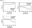
Fig. 1 is a graph showing the results of evaluation of the charge and discharge performance of a unit cell including the separation membrane complex of Example 1 and Comparative Example 1. -
FIG. 2 is a schematic diagram of a unit cell for confirming the performance of the separation membrane complex of Example 1 and Comparative Example 1. - Hereinafter, the present disclosure will be described in more detail with reference to examples. However, these Examples are presented only to illustrate the invention and the scope of the present disclosure is not limited thereto.
- An anion exchange resin (trimethylammonium functionalized polysulfone) was spin-coated on a silica mold that had been subjected to a hydrophilic treatment through a process such as plasma at 3000 rpm for 60 seconds. It was dried at a temperature of 80°C for 3 hours, and the silicon mold coated with the anion exchange resin was impregnated with deionized water to obtain an anion exchange resin membrane.
- At this time, in the anion exchange resin film, a plurality of concavities and convexities were formed on the substrate surface having a thickness of about 10 µm at a height of about 40 µm and a spacing of about 20 µm.
- Then, a 25 µm thick Nafion (Nafion D520, DuPont) was placed on the anion-exchange resin film on which the concavities and convexities were formed, and thermally pressed at a temperature of 130°C under a pressure of 5 atm to prepare a separation membrane complex.
- A 50 µm thick Nafion (Nafion 212, DuPont) separation membrane was used.
- In order to confirm the performance of the separation membrane of Example 1 and Comparative Example 1, a unit cell was prepared as shown in
FIG 2 . The unit cell is composed of aflow frame 50 for forming a flow path so that the electrolyte can move symmetrically to theseparation membrane 60, anelectrode 40 for moving electrons, and anend plate 30 that serves to maintain a unit cell shape and plays a role as a support. The electrolyte in the electrolyte container was supplied to the unit cell via a pump, and an electric current was applied through a charging/dischargingdevice 70 so that charging and discharging were performed. - As the electrolyte solution stored in the electrolyte container, a solution in which 1.5M VOSO4 was dissolved in 3M H2SO4 aqueous solution was used. The electrolyte used an anode and a cathode in an amount of 40ml, respectively, and the electrolyte supplied from an electrolyte circulating pump was supplied at a rate of 40 ml/min. In addition, the anode electrolyte was used as a V(+4)/V(+5) redox couple, and the cathode electrolyte was used as a V(+2)/V(+3) redox couple.
- With respect to the unit cells prepared by the separation membranes of Example 1 and Comparative Example 1, one stripping after one charge/discharge process was set to 1 cycle, and the energy efficiency, voltage efficiency and charge efficiency were measured. The results are shown in Table 1 below. At this time, the voltage efficiency [VE, the calculation method is the average discharge voltage(V)/average charge voltage(V)] was measured by dividing the average charge voltage and the average discharge voltage, and the energy efficiency (EE, the calculation method is the charge output amount(Wh) / discharge output amount(Wh)) was measured by dividing the charge output amount and the discharge output amount.
- At this time, Wonatec product was used as a charge/discharge device, and the measurement was performed under the conditions of room temperature, total charge of the system of 1.6 Ah, charge/discharge voltage range of 0.8 to 1.6Ah, charge of 80mA/cm2, discharge of 80mA/cm2, and voltage of less than 0.01V.
[Table 1] Unit: % (28 cycle average) Energy efficiency Voltage efficiency Charge efficiency Example 1 81.77 83.01 98.49 Comparative Example 1 69.77 78.15 89.39 - As shown in Table 1 and
FIG. 1 , it was confirmed that the unit cell including the separation membrane of Example 1 was significantly superior in energy efficiency, voltage efficiency, and charge efficiency compared to the unit cell including the separation membrane of Comparative Example 1. -
- 30: end plate
- 40: electrode
- 50: flow frame
- 60: separation membrane
- 70: charge/discharge device
Claims (7)
- A separation membrane complex having an anion exchange membrane and a cation exchange membrane coming in face-to-face contact with each other, the cation exchange membrane and the anion exchange membrane each having two or more concavities and convexities which interlock with each other in a reverse phase.
- The separation membrane complex of claim 1, wherein a height of the anion exchange membrane is 1 µm to 200 µm.
- The separation membrane complex of claim 1, wherein a width of the fine concavities and convexities of the anion exchange membrane is 1µm to 200µm.
- The separation membrane complex of claim 1, wherein the distance between the concavities and convexities adjacent to each other in the anion exchange membrane is 1 µm to 200 µm.
- The separation membrane complex of claim 1, wherein the separation membrane complex is used for a redox flow battery.
- The separation membrane complex of claim 1, wherein the anion exchange membrane includes an anion exchange polymer in which one or more anion exchange functional groups selected from the group consisting of ammonium, phosphonium and sulfonium are substituted.
- The separation membrane complex of claim 1, wherein the cation exchange membrane includes a cationic polymer in which one or more cation exchange functional groups selected from the group consisting of a sulfonic acid group, a carboxyl group and a phosphoric acid group are substituted.
Applications Claiming Priority (2)
| Application Number | Priority Date | Filing Date | Title |
|---|---|---|---|
| KR1020170119832A KR102066239B1 (en) | 2017-09-18 | 2017-09-18 | Separator complex and redox flow battery |
| PCT/KR2018/010708 WO2019054759A1 (en) | 2017-09-18 | 2018-09-12 | Separation film complex and redox flow battery |
Publications (2)
| Publication Number | Publication Date |
|---|---|
| EP3686980A1 true EP3686980A1 (en) | 2020-07-29 |
| EP3686980A4 EP3686980A4 (en) | 2021-06-02 |
Family
ID=65724005
Family Applications (1)
| Application Number | Title | Priority Date | Filing Date |
|---|---|---|---|
| EP18856787.9A Pending EP3686980A4 (en) | 2017-09-18 | 2018-09-12 | SEPARATION FILM COMPLEX AND REDOX FLOW BATTERY |
Country Status (6)
| Country | Link |
|---|---|
| US (1) | US11374234B2 (en) |
| EP (1) | EP3686980A4 (en) |
| JP (1) | JP6980184B2 (en) |
| KR (1) | KR102066239B1 (en) |
| CN (1) | CN111201655B (en) |
| WO (1) | WO2019054759A1 (en) |
Families Citing this family (2)
| Publication number | Priority date | Publication date | Assignee | Title |
|---|---|---|---|---|
| CN111370723B (en) * | 2020-03-19 | 2021-04-09 | 辽宁科京新材料科技有限公司 | Preparation method of perfluorosulfonic acid membrane with adjustable and controllable microstructure |
| US20250239630A1 (en) * | 2022-02-15 | 2025-07-24 | Daramic, Llc | Porous membranes for flow batteries and batteries including such membranes |
Family Cites Families (35)
| Publication number | Priority date | Publication date | Assignee | Title |
|---|---|---|---|---|
| JPS5937292B2 (en) | 1977-10-03 | 1984-09-08 | 旭化成株式会社 | Polyolefin resin porous membrane, alkaline storage battery separator, and microfilter |
| JPS59205165A (en) * | 1983-05-09 | 1984-11-20 | Asahi Chem Ind Co Ltd | Diaphragm for redox battery and its use |
| JP2524012B2 (en) | 1990-05-31 | 1996-08-14 | 株式会社トクヤマ | Bipolar film and manufacturing method thereof |
| JP3134016B2 (en) * | 1992-05-14 | 2001-02-13 | 株式会社トクヤマ | Bipolar membrane |
| US5304432A (en) * | 1992-10-13 | 1994-04-19 | Hughes Aircraft Company | Membrane flow cell battery |
| JPH06260183A (en) | 1993-03-04 | 1994-09-16 | Sumitomo Electric Ind Ltd | Diaphragm for water-solvent electrochemical device and water-solvent battery using the same |
| JPH0992321A (en) | 1995-09-27 | 1997-04-04 | Kashimakita Kyodo Hatsuden Kk | Redox cell |
| JP3729386B2 (en) | 1997-10-21 | 2005-12-21 | オルガノ株式会社 | Electric deionized water production equipment |
| JPH11260390A (en) | 1998-03-05 | 1999-09-24 | Kashimakita Kyodo Hatsuden Kk | Redox flow battery |
| JP4830190B2 (en) * | 1999-09-27 | 2011-12-07 | 住友電気工業株式会社 | Redox flow battery |
| PT1143546E (en) | 1999-09-27 | 2009-11-27 | Sumitomo Electric Industries | Redox flow battery |
| KR100441376B1 (en) | 2002-01-31 | 2004-07-23 | (주)퓨얼셀 파워 | A very thin Composite membrane |
| CN2561499Y (en) * | 2002-08-07 | 2003-07-23 | 浙江欧美环境工程有限公司 | Convex cloumn stylei on exchange film with equal thickness |
| US7959780B2 (en) * | 2004-07-26 | 2011-06-14 | Emporia Capital Funding Llc | Textured ion exchange membranes |
| US20100028736A1 (en) * | 2008-08-01 | 2010-02-04 | Georgia Tech Research Corporation | Hybrid Ionomer Electrochemical Devices |
| JP5339878B2 (en) | 2008-12-08 | 2013-11-13 | 株式会社アストム | Bipolar membrane and manufacturing method thereof |
| KR101042931B1 (en) | 2009-03-03 | 2011-06-21 | 세방산업 주식회사 | Method for producing polyolefin microporous membrane |
| WO2011038190A1 (en) * | 2009-09-24 | 2011-03-31 | Georgia Tech Research Corporation | Electrochemical devices based on multiple junction ionic conductive membranes |
| EP2638189A1 (en) * | 2010-11-12 | 2013-09-18 | Siemens Pte Ltd. | Modular electrochemical systems and methods |
| KR101265201B1 (en) * | 2011-04-18 | 2013-05-24 | 삼성에스디아이 주식회사 | Separator for redox flow battery and redox flow battery |
| KR101261703B1 (en) | 2011-04-27 | 2013-05-06 | 한국과학기술원 | Method for improving capacity retention of lithium secondary cell, separator for the same, manufacturing method for the separator, and secondary cell comprising the same |
| CN103620846A (en) | 2011-06-17 | 2014-03-05 | 纳幕尔杜邦公司 | Improved composite polymer electrolyte membrane |
| KR101351280B1 (en) | 2011-09-02 | 2014-01-22 | 충남대학교산학협력단 | Anion exchange membrane for redox flow battery and method for preparing the same |
| CN105845958B (en) | 2011-12-28 | 2018-04-06 | 旭化成株式会社 | Oxidation, reduction liquid secondary cell and oxidation, reduction liquid secondary cell Electrolyte Membranes |
| NL2008538C2 (en) * | 2012-03-26 | 2013-09-30 | Stichting Wetsus Ct Excellence Sustainable Water Technology | Energy generating system using capacitive electrodes and method there for. |
| KR101322127B1 (en) * | 2012-05-11 | 2013-10-28 | 주식회사 포스코 | Separator-collector assembly, fuel cell stack having thereof and manufacturing method thereof |
| KR20130132107A (en) | 2012-05-25 | 2013-12-04 | 삼성전자주식회사 | Ion exchange membrane filling composition, method of preparing ion exchange membrane, ion exchange membrane and redox flow battery |
| EP2888205B1 (en) * | 2012-08-27 | 2018-10-24 | Merck Patent GmbH | Improved electrodeionization module and apparatus |
| KR20140119598A (en) | 2013-04-01 | 2014-10-10 | 황완석 | How to make the Redox flow battery for nanocomposite membrane |
| CA2924686C (en) | 2013-09-25 | 2024-02-13 | Lockheed Martin Advanced Energy Storage, Llc | Electrolyte balancing strategies for flow batteries |
| KR101633908B1 (en) * | 2014-02-19 | 2016-06-27 | 전남대학교산학협력단 | Coated membrane with low permeability, method for fabricating the same and redox flow battery comprising the same |
| KR101648844B1 (en) | 2014-05-19 | 2016-08-17 | 한국화학연구원 | Seperator membrane made of ion-conducting polymer comprising phenyl pendant substituted with at least two sulfonated aromatic groups and redox flow batteries comprising the same |
| JP6563279B2 (en) * | 2014-09-05 | 2019-08-21 | 日本特殊陶業株式会社 | Method for producing a single fuel cell |
| US10411285B2 (en) | 2015-04-14 | 2019-09-10 | Lockheed Martin Energy, Llc | Flow battery balancing cells having a bipolar membrane for simultaneous modification of a negative electrolyte solution and a positive electrolyte solution |
| CN107171010A (en) * | 2017-05-11 | 2017-09-15 | 厦门大学 | A kind of compound Bipolar Membrane and preparation method thereof |
-
2017
- 2017-09-18 KR KR1020170119832A patent/KR102066239B1/en active Active
-
2018
- 2018-09-12 US US16/648,124 patent/US11374234B2/en active Active
- 2018-09-12 WO PCT/KR2018/010708 patent/WO2019054759A1/en not_active Ceased
- 2018-09-12 CN CN201880060347.1A patent/CN111201655B/en active Active
- 2018-09-12 EP EP18856787.9A patent/EP3686980A4/en active Pending
- 2018-09-12 JP JP2020513624A patent/JP6980184B2/en active Active
Also Published As
| Publication number | Publication date |
|---|---|
| US20200235408A1 (en) | 2020-07-23 |
| WO2019054759A1 (en) | 2019-03-21 |
| US11374234B2 (en) | 2022-06-28 |
| WO2019054759A8 (en) | 2020-02-20 |
| JP6980184B2 (en) | 2021-12-15 |
| KR102066239B1 (en) | 2020-01-14 |
| EP3686980A4 (en) | 2021-06-02 |
| CN111201655A (en) | 2020-05-26 |
| KR20190031864A (en) | 2019-03-27 |
| JP2020532844A (en) | 2020-11-12 |
| CN111201655B (en) | 2023-08-29 |
Similar Documents
| Publication | Publication Date | Title |
|---|---|---|
| Ye et al. | Redox flow batteries for energy storage: a technology review | |
| Li et al. | Ion exchange membranes for vanadium redox flow battery (VRB) applications | |
| US9147903B2 (en) | Separator for redox flow battery and redox flow battery | |
| Amiri et al. | Designing ion‐selective membranes for vanadium redox flow batteries | |
| US11980879B2 (en) | Anion exchange polymers and membranes for electrolysis | |
| US20220093954A1 (en) | Separator for redox flow battery and manufacturing method therefor | |
| Qian et al. | Review and perspectives of sulfonated poly (ether ether ketone) proton exchange membrane for vanadium flow batteries | |
| US20120301767A1 (en) | Redox flow battery | |
| KR101851849B1 (en) | Polymer electrolyte membrane, electrochemical cell comprising the polymer electrolyte membrane, electrochemical cell module having the electrochemical cell, flow battery including polymer electrolyte membrane, method of manufacturing the polymer electrolyte membrane and electrolyte for flow battery | |
| Jiang et al. | The structure–activity relationship in membranes for vanadium redox flow batteries | |
| US11374234B2 (en) | Separation membrane complex and redox flow battery | |
| Hosseiny et al. | Ion exchange membranes for vanadium redox flow batteries | |
| KR20190026530A (en) | Separator of redox flow battery, preparation method for separator of flow battery, and redox flow battery | |
| KR102098447B1 (en) | Polymer electrolyte membrane, electrochemical cell and fuel cell comprising the polymer electrolyte membrane, composition for polymer electrolyte membrane, and method of manufacturing polymer electrolyte membrane | |
| KR102232262B1 (en) | Composite separator for redox flow battery and redox flow battery comprising the same | |
| US20240194901A1 (en) | Separator for secondary battery and method of fabricating same | |
| KR102706751B1 (en) | Method for manufacturing electrolyte membrane | |
| KR102092997B1 (en) | Ion exchange membrane, electrochemical cell, flow battery and fuel cell comprising the same, and method for manufacturing the same | |
| KR20170003276A (en) | Manufacturing methode of reinforced membrane, manufacturing apparatus of reinforced membrane and reinforced membrane | |
| US12255369B2 (en) | Zipped ion-exchange membrane | |
| Bora et al. | Membranes for Redox Flow Batteries | |
| KR102293564B1 (en) | Reinforced membrane, electrochemical cell and fuel cell comprising the same, and method for manufacturing the reinforced membrane | |
| Altalhi | Advanced Redox Flow Technology | |
| EP3252036A1 (en) | Compound comprising aromatic ring and polymer electrolyte membrane using same | |
| JP2026503367A (en) | Polybenzimidazole-based separator for secondary battery and method for producing same |
Legal Events
| Date | Code | Title | Description |
|---|---|---|---|
| STAA | Information on the status of an ep patent application or granted ep patent |
Free format text: STATUS: THE INTERNATIONAL PUBLICATION HAS BEEN MADE |
|
| PUAI | Public reference made under article 153(3) epc to a published international application that has entered the european phase |
Free format text: ORIGINAL CODE: 0009012 |
|
| STAA | Information on the status of an ep patent application or granted ep patent |
Free format text: STATUS: REQUEST FOR EXAMINATION WAS MADE |
|
| 17P | Request for examination filed |
Effective date: 20200309 |
|
| AK | Designated contracting states |
Kind code of ref document: A1 Designated state(s): AL AT BE BG CH CY CZ DE DK EE ES FI FR GB GR HR HU IE IS IT LI LT LU LV MC MK MT NL NO PL PT RO RS SE SI SK SM TR |
|
| AX | Request for extension of the european patent |
Extension state: BA ME |
|
| DAV | Request for validation of the european patent (deleted) | ||
| DAX | Request for extension of the european patent (deleted) | ||
| A4 | Supplementary search report drawn up and despatched |
Effective date: 20210503 |
|
| RIC1 | Information provided on ipc code assigned before grant |
Ipc: H01M 8/1053 20160101AFI20210427BHEP Ipc: H01M 8/0221 20160101ALI20210427BHEP Ipc: H01M 8/0228 20160101ALI20210427BHEP Ipc: H01M 8/0247 20160101ALI20210427BHEP Ipc: H01M 8/18 20060101ALI20210427BHEP |
|
| STAA | Information on the status of an ep patent application or granted ep patent |
Free format text: STATUS: EXAMINATION IS IN PROGRESS |
|
| 17Q | First examination report despatched |
Effective date: 20231017 |