EP3686604A1 - Microdevice for detecting aldehydes or ketones - Google Patents
Microdevice for detecting aldehydes or ketones Download PDFInfo
- Publication number
- EP3686604A1 EP3686604A1 EP18924573.1A EP18924573A EP3686604A1 EP 3686604 A1 EP3686604 A1 EP 3686604A1 EP 18924573 A EP18924573 A EP 18924573A EP 3686604 A1 EP3686604 A1 EP 3686604A1
- Authority
- EP
- European Patent Office
- Prior art keywords
- ketones
- aldehydes
- eluent
- detection part
- microfluidic channel
- Prior art date
- Legal status (The legal status is an assumption and is not a legal conclusion. Google has not performed a legal analysis and makes no representation as to the accuracy of the status listed.)
- Granted
Links
Images




Classifications
-
- B—PERFORMING OPERATIONS; TRANSPORTING
- B01—PHYSICAL OR CHEMICAL PROCESSES OR APPARATUS IN GENERAL
- B01L—CHEMICAL OR PHYSICAL LABORATORY APPARATUS FOR GENERAL USE
- B01L3/00—Containers or dishes for laboratory use, e.g. laboratory glassware; Droppers
- B01L3/50—Containers for the purpose of retaining a material to be analysed, e.g. test tubes
- B01L3/502—Containers for the purpose of retaining a material to be analysed, e.g. test tubes with fluid transport, e.g. in multi-compartment structures
- B01L3/5027—Containers for the purpose of retaining a material to be analysed, e.g. test tubes with fluid transport, e.g. in multi-compartment structures by integrated microfluidic structures, i.e. dimensions of channels and chambers are such that surface tension forces are important, e.g. lab-on-a-chip
- B01L3/502715—Containers for the purpose of retaining a material to be analysed, e.g. test tubes with fluid transport, e.g. in multi-compartment structures by integrated microfluidic structures, i.e. dimensions of channels and chambers are such that surface tension forces are important, e.g. lab-on-a-chip characterised by interfacing components, e.g. fluidic, electrical, optical or mechanical interfaces
-
- G—PHYSICS
- G01—MEASURING; TESTING
- G01N—INVESTIGATING OR ANALYSING MATERIALS BY DETERMINING THEIR CHEMICAL OR PHYSICAL PROPERTIES
- G01N35/00—Automatic analysis not limited to methods or materials provided for in any single one of groups G01N1/00 - G01N33/00; Handling materials therefor
- G01N35/00029—Automatic analysis not limited to methods or materials provided for in any single one of groups G01N1/00 - G01N33/00; Handling materials therefor provided with flat sample substrates, e.g. slides
- G01N35/00069—Automatic analysis not limited to methods or materials provided for in any single one of groups G01N1/00 - G01N33/00; Handling materials therefor provided with flat sample substrates, e.g. slides whereby the sample substrate is of the bio-disk type, i.e. having the format of an optical disk
-
- B—PERFORMING OPERATIONS; TRANSPORTING
- B01—PHYSICAL OR CHEMICAL PROCESSES OR APPARATUS IN GENERAL
- B01L—CHEMICAL OR PHYSICAL LABORATORY APPARATUS FOR GENERAL USE
- B01L3/00—Containers or dishes for laboratory use, e.g. laboratory glassware; Droppers
-
- B—PERFORMING OPERATIONS; TRANSPORTING
- B01—PHYSICAL OR CHEMICAL PROCESSES OR APPARATUS IN GENERAL
- B01L—CHEMICAL OR PHYSICAL LABORATORY APPARATUS FOR GENERAL USE
- B01L3/00—Containers or dishes for laboratory use, e.g. laboratory glassware; Droppers
- B01L3/50—Containers for the purpose of retaining a material to be analysed, e.g. test tubes
- B01L3/502—Containers for the purpose of retaining a material to be analysed, e.g. test tubes with fluid transport, e.g. in multi-compartment structures
- B01L3/5027—Containers for the purpose of retaining a material to be analysed, e.g. test tubes with fluid transport, e.g. in multi-compartment structures by integrated microfluidic structures, i.e. dimensions of channels and chambers are such that surface tension forces are important, e.g. lab-on-a-chip
-
- G—PHYSICS
- G01—MEASURING; TESTING
- G01N—INVESTIGATING OR ANALYSING MATERIALS BY DETERMINING THEIR CHEMICAL OR PHYSICAL PROPERTIES
- G01N1/00—Sampling; Preparing specimens for investigation
- G01N1/28—Preparing specimens for investigation including physical details of (bio-)chemical methods covered elsewhere, e.g. G01N33/50, C12Q
-
- G—PHYSICS
- G01—MEASURING; TESTING
- G01N—INVESTIGATING OR ANALYSING MATERIALS BY DETERMINING THEIR CHEMICAL OR PHYSICAL PROPERTIES
- G01N21/00—Investigating or analysing materials by the use of optical means, i.e. using sub-millimetre waves, infrared, visible or ultraviolet light
- G01N21/17—Systems in which incident light is modified in accordance with the properties of the material investigated
- G01N21/25—Colour; Spectral properties, i.e. comparison of effect of material on the light at two or more different wavelengths or wavelength bands
- G01N21/31—Investigating relative effect of material at wavelengths characteristic of specific elements or molecules, e.g. atomic absorption spectrometry
- G01N21/33—Investigating relative effect of material at wavelengths characteristic of specific elements or molecules, e.g. atomic absorption spectrometry using ultraviolet light
-
- G—PHYSICS
- G01—MEASURING; TESTING
- G01N—INVESTIGATING OR ANALYSING MATERIALS BY DETERMINING THEIR CHEMICAL OR PHYSICAL PROPERTIES
- G01N33/00—Investigating or analysing materials by specific methods not covered by groups G01N1/00 - G01N31/00
- G01N33/48—Biological material, e.g. blood, urine; Haemocytometers
- G01N33/50—Chemical analysis of biological material, e.g. blood, urine; Testing involving biospecific ligand binding methods; Immunological testing
- G01N33/64—Chemical analysis of biological material, e.g. blood, urine; Testing involving biospecific ligand binding methods; Immunological testing involving ketones
-
- G—PHYSICS
- G01—MEASURING; TESTING
- G01N—INVESTIGATING OR ANALYSING MATERIALS BY DETERMINING THEIR CHEMICAL OR PHYSICAL PROPERTIES
- G01N35/00—Automatic analysis not limited to methods or materials provided for in any single one of groups G01N1/00 - G01N33/00; Handling materials therefor
- G01N35/08—Automatic analysis not limited to methods or materials provided for in any single one of groups G01N1/00 - G01N33/00; Handling materials therefor using a stream of discrete samples flowing along a tube system, e.g. flow injection analysis
- G01N35/085—Flow Injection Analysis
-
- B—PERFORMING OPERATIONS; TRANSPORTING
- B01—PHYSICAL OR CHEMICAL PROCESSES OR APPARATUS IN GENERAL
- B01L—CHEMICAL OR PHYSICAL LABORATORY APPARATUS FOR GENERAL USE
- B01L2200/00—Solutions for specific problems relating to chemical or physical laboratory apparatus
- B01L2200/10—Integrating sample preparation and analysis in single entity, e.g. lab-on-a-chip concept
-
- B—PERFORMING OPERATIONS; TRANSPORTING
- B01—PHYSICAL OR CHEMICAL PROCESSES OR APPARATUS IN GENERAL
- B01L—CHEMICAL OR PHYSICAL LABORATORY APPARATUS FOR GENERAL USE
- B01L2200/00—Solutions for specific problems relating to chemical or physical laboratory apparatus
- B01L2200/16—Reagents, handling or storing thereof
-
- B—PERFORMING OPERATIONS; TRANSPORTING
- B01—PHYSICAL OR CHEMICAL PROCESSES OR APPARATUS IN GENERAL
- B01L—CHEMICAL OR PHYSICAL LABORATORY APPARATUS FOR GENERAL USE
- B01L2300/00—Additional constructional details
- B01L2300/06—Auxiliary integrated devices, integrated components
- B01L2300/0627—Sensor or part of a sensor is integrated
-
- B—PERFORMING OPERATIONS; TRANSPORTING
- B01—PHYSICAL OR CHEMICAL PROCESSES OR APPARATUS IN GENERAL
- B01L—CHEMICAL OR PHYSICAL LABORATORY APPARATUS FOR GENERAL USE
- B01L2300/00—Additional constructional details
- B01L2300/08—Geometry, shape and general structure
- B01L2300/0803—Disc shape
-
- B—PERFORMING OPERATIONS; TRANSPORTING
- B01—PHYSICAL OR CHEMICAL PROCESSES OR APPARATUS IN GENERAL
- B01L—CHEMICAL OR PHYSICAL LABORATORY APPARATUS FOR GENERAL USE
- B01L2300/00—Additional constructional details
- B01L2300/08—Geometry, shape and general structure
- B01L2300/0861—Configuration of multiple channels and/or chambers in a single devices
- B01L2300/087—Multiple sequential chambers
-
- B—PERFORMING OPERATIONS; TRANSPORTING
- B01—PHYSICAL OR CHEMICAL PROCESSES OR APPARATUS IN GENERAL
- B01L—CHEMICAL OR PHYSICAL LABORATORY APPARATUS FOR GENERAL USE
- B01L2300/00—Additional constructional details
- B01L2300/08—Geometry, shape and general structure
- B01L2300/0861—Configuration of multiple channels and/or chambers in a single devices
- B01L2300/088—Channel loops
-
- B—PERFORMING OPERATIONS; TRANSPORTING
- B01—PHYSICAL OR CHEMICAL PROCESSES OR APPARATUS IN GENERAL
- B01L—CHEMICAL OR PHYSICAL LABORATORY APPARATUS FOR GENERAL USE
- B01L2300/00—Additional constructional details
- B01L2300/10—Means to control humidity and/or other gases
-
- B—PERFORMING OPERATIONS; TRANSPORTING
- B01—PHYSICAL OR CHEMICAL PROCESSES OR APPARATUS IN GENERAL
- B01L—CHEMICAL OR PHYSICAL LABORATORY APPARATUS FOR GENERAL USE
- B01L2300/00—Additional constructional details
- B01L2300/16—Surface properties and coatings
-
- B—PERFORMING OPERATIONS; TRANSPORTING
- B01—PHYSICAL OR CHEMICAL PROCESSES OR APPARATUS IN GENERAL
- B01L—CHEMICAL OR PHYSICAL LABORATORY APPARATUS FOR GENERAL USE
- B01L2400/00—Moving or stopping fluids
- B01L2400/04—Moving fluids with specific forces or mechanical means
- B01L2400/0403—Moving fluids with specific forces or mechanical means specific forces
- B01L2400/0406—Moving fluids with specific forces or mechanical means specific forces capillary forces
-
- B—PERFORMING OPERATIONS; TRANSPORTING
- B01—PHYSICAL OR CHEMICAL PROCESSES OR APPARATUS IN GENERAL
- B01L—CHEMICAL OR PHYSICAL LABORATORY APPARATUS FOR GENERAL USE
- B01L2400/00—Moving or stopping fluids
- B01L2400/04—Moving fluids with specific forces or mechanical means
- B01L2400/0403—Moving fluids with specific forces or mechanical means specific forces
- B01L2400/0409—Moving fluids with specific forces or mechanical means specific forces centrifugal forces
-
- B—PERFORMING OPERATIONS; TRANSPORTING
- B01—PHYSICAL OR CHEMICAL PROCESSES OR APPARATUS IN GENERAL
- B01L—CHEMICAL OR PHYSICAL LABORATORY APPARATUS FOR GENERAL USE
- B01L2400/00—Moving or stopping fluids
- B01L2400/04—Moving fluids with specific forces or mechanical means
- B01L2400/0403—Moving fluids with specific forces or mechanical means specific forces
- B01L2400/0466—Evaporation to induce underpressure
-
- B—PERFORMING OPERATIONS; TRANSPORTING
- B01—PHYSICAL OR CHEMICAL PROCESSES OR APPARATUS IN GENERAL
- B01L—CHEMICAL OR PHYSICAL LABORATORY APPARATUS FOR GENERAL USE
- B01L3/00—Containers or dishes for laboratory use, e.g. laboratory glassware; Droppers
- B01L3/50—Containers for the purpose of retaining a material to be analysed, e.g. test tubes
- B01L3/502—Containers for the purpose of retaining a material to be analysed, e.g. test tubes with fluid transport, e.g. in multi-compartment structures
- B01L3/5027—Containers for the purpose of retaining a material to be analysed, e.g. test tubes with fluid transport, e.g. in multi-compartment structures by integrated microfluidic structures, i.e. dimensions of channels and chambers are such that surface tension forces are important, e.g. lab-on-a-chip
- B01L3/502723—Containers for the purpose of retaining a material to be analysed, e.g. test tubes with fluid transport, e.g. in multi-compartment structures by integrated microfluidic structures, i.e. dimensions of channels and chambers are such that surface tension forces are important, e.g. lab-on-a-chip characterised by venting arrangements
-
- G—PHYSICS
- G01—MEASURING; TESTING
- G01N—INVESTIGATING OR ANALYSING MATERIALS BY DETERMINING THEIR CHEMICAL OR PHYSICAL PROPERTIES
- G01N35/00—Automatic analysis not limited to methods or materials provided for in any single one of groups G01N1/00 - G01N33/00; Handling materials therefor
- G01N35/00029—Automatic analysis not limited to methods or materials provided for in any single one of groups G01N1/00 - G01N33/00; Handling materials therefor provided with flat sample substrates, e.g. slides
- G01N2035/00099—Characterised by type of test elements
- G01N2035/00158—Elements containing microarrays, i.e. "biochip"
-
- G—PHYSICS
- G01—MEASURING; TESTING
- G01N—INVESTIGATING OR ANALYSING MATERIALS BY DETERMINING THEIR CHEMICAL OR PHYSICAL PROPERTIES
- G01N35/00—Automatic analysis not limited to methods or materials provided for in any single one of groups G01N1/00 - G01N33/00; Handling materials therefor
- G01N2035/00465—Separating and mixing arrangements
- G01N2035/00564—Handling or washing solid phase elements, e.g. beads
-
- G—PHYSICS
- G01—MEASURING; TESTING
- G01N—INVESTIGATING OR ANALYSING MATERIALS BY DETERMINING THEIR CHEMICAL OR PHYSICAL PROPERTIES
- G01N30/00—Investigating or analysing materials by separation into components using adsorption, absorption or similar phenomena or using ion-exchange, e.g. chromatography or field flow fractionation
- G01N30/02—Column chromatography
- G01N30/60—Construction of the column
- G01N30/6095—Micromachined or nanomachined, e.g. micro- or nanosize
Definitions
- the present invention relates to a device and a system for detecting aldehydes or ketones, and more specifically, to a device and a system for detecting aldehydes or ketones using a rotatable platform.
- aldehyde has no chromophore and UV detection is impossible. Therefore, it is common to conduct derivatization with an acetyl acetone reagent or a 2,4-dinitrophenylhydrazine (DNPH) reagent and then to detect the aldehyde using High Performance Liquid Chromatography (HPLC).
- the method using acetyl acetone is a derivatization method wherein the acetyl acetone selectively reacts with formaldehyde
- the method using DNPH is a method of analyzing DNPH derivatives produced by the reaction between carbonyl compounds and DNPH by reacting with the carbonyl compounds.
- commercially available DNPH cartridges are used for aldehydes and ketones existing in the air. Since conventional methods require expensive equipment and skilled analytical techniques, it is difficult to perform analysis of aldehydes or ketones quickly and simply in the field.
- the device for detecting aldehydes or ketones according to the present invention may comprise:
- the aldehydes or ketones which can be contained in the sample may be at least one selected from the group consisting of acetaldehyde, acetone, acrolein, benzaldehyde, butyraldehyde, formaldehyde and propionaldehyde.
- the inside of the sample injection part may be filled with 2,4-DNPH coated silica in the form of beads.
- the microfluidic structure may be provided in a plurality, and the plurality of microfluidic structures can accommodate different fluidic samples, respectively, and may be disposed radially symmetrically on the rotatable platform.
- the microfluidic structure may comprise a reserve area connecting the second microfluidic channel and the detection part, and one end of the detection part may be accommodated in the reserve area.
- the microfluidic structure may further comprise: a first air circulation channel connecting the sample injection part and the other end of the detection part; and a second air circulation channel connecting the eluent introduction part and the other end of the detection part, wherein the first air circulation channel and the second air circulation channel may increase the evaporation rate of the fluidic sample and the eluent in the detection part and prevent moisture condensation in the detection part.
- the first microfluidic channel and the second microfluidic channel may comprise bending parts, respectively, and the number of the bending part of the second microfluidic channel may be one more than the number of the bending part of the first microfluidic channel.
- the injected fluidic sample may move to the rear end of the sample injection part, and the injected eluent may move to the rear end of the eluent introduction part; upon stopping the device after the first rotation of the device, the sample may move from the sample injection part to the first microfluidic channel, and the eluent may move from the eluent introduction part to the first bending part of the second microfluidic channel; during the second rotation of the device, the sample may be introduced from the first microfluidic channel to the detection part; upon stopping the device after the second rotation of the device, the eluent may move from the first bending part of the second microfluidic channel to the second bending part of the second microfluidic channel; during the third rotation of the device, the eluent may be introduced from the second microfluidic channel to the reserve area; and upon stopping the device after the third rotation of the device, the
- a system for detecting aldehydes or ketones comprising: the device for detecting aldehydes or ketones according to the present invention, and a UV lamp for visually observing the aldehydes or ketones separated and developed on the detection part by irradiating UV to the detection part may be provided.
- the device for detecting aldehydes or ketones according to the present invention may comprise:
- the aldehydes or ketones which can be contained in the sample may be at least one selected from the group consisting of acetaldehyde, acetone, acrolein, benzaldehyde, butyraldehyde, formaldehyde and propionaldehyde.
- the inside of the sample injection part may be filled with 2,4-DNPH coated silica in the form of beads.
- the microfluidic structure may be provided in a plurality, and the plurality of microfluidic structures can accommodate different fluidic samples, respectively, and may be disposed radially symmetrically on the rotatable platform.
- the microfluidic structure may comprise the reserve area connecting the second microfluidic channel and the detection part, and one end of the detection part may be accommodated in the reserve area.
- the microfluidic structure may further comprise: a first air circulation channel connecting the sample injection part and the other end of the detection part; and a second air circulation channel connecting the eluent introduction part and the other end of the detection part, wherein the first air circulation channel and the second air circulation channel may increase the evaporation rate of the fluidic sample and the eluent in the detection part and may prevent moisture condensation in the detection part.
- the first microfluidic channel and the second microfluidic channel may comprise bending parts, respectively, and the number of the bending part of the second microfluidic channel may be one more than the number of the bending part of the first microfluidic channel.
- the injected fluidic sample may move to the rear end of the sample injection part, and the injected eluent may move to the rear end of the eluent introduction part; upon stopping the device after the first rotation of the device, the sample may move from the sample injection part to the first microfluidic channel, and the eluent may move from the eluent introduction part to the first bending part of the second microfluidic channel; during the second rotation of the device, the sample may be introduced from the first microfluidic channel to the detection part; upon stopping the device after the second rotation of the device, the eluent may move from the first bending part of the second microfluidic channel to the second bending part of the second microfluidic channel; during the third rotation of the device, the eluent may be introduced from the second microfluidic channel to the reserve area; and upon stopping the device after the third rotation of the device, the
- a system for detecting aldehydes or ketones comprising: the device for detecting aldehydes or ketones according to the present invention, and a UV lamp for visually observing the aldehydes or ketones separated and developed on the detection part by irradiating UV to the detection part can be provided.
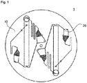
- Fig. 1 illustrates the device for detecting aldehydes and/or ketones 1 according to one embodiment of the present invention
- Fig. 2 illustrates a microfluidic structure 20 of the rotatable disk system of Fig. 1 .
- the device for detecting aldehydes and/or ketones 1 comprises a rotatable platform 10 and a microfluidic structure 20 equipped in the rotatable platform 10.
- the rotatable platform 10 may be, for example, a circular disk, and its size may be, for example, 14 cm to 17 cm in diameter.
- the rotatable platform 10 contains the microfluidic structure 20.
- the rotatable platform 10 may contain one microfluidic structure 20, or a plurality of microfluidic structures 20.
- the plurality of microfluidic structures 20 is disposed radially symmetrically on the rotatable platform 10.
- Fig 1 illustrates the case that two microfluidic structures 20 are disposed on the rotatable platform 10.
- three, four, five, six or more microfluidic structures can be disposed.
- Fig. 2 illustrates the microfluidic structure 20 of each of the plurality of microfluidic structures 20.
- the microfluidic structure 20 comprises: a sample injection part 100 where a fluidic sample containing the aldehydes or ketones is injected and a first microfluidic channel (siphon channel) 110 that is a passage through which the fluidic sample can move from the sample injection part 100 to a detection part 120, the detection part 120 that can separate and detect multiple aldehydes or ketones contained in the fluidic sample, an eluent introduction part 130, a second microfluidic channel 140 that is a passage through which the eluent can move from the eluent introduction part 130 to the detection part 120, and a reserve area 150 that connects the second microfluidic channel 140 and the detection part 120.
- a sample injection part 100 where a fluidic sample containing the aldehydes or ketones is injected
- a first microfluidic channel (siphon channel) 110 that is a passage
- the microfluidic structure 20 can accommodate the fluidic samples containing a plurality of aldehydes and/or ketones and then can separate and detect the aldehydes and/or ketones.
- the aldehydes and/or ketones that can be contained in the fluidic sample may be, for example, at least one selected from the group consisting of acetaldehyde, acetone, acrolein, benzaldehyde, butyraldehyde, formaldehyde and propionaldehyde.
- the sample injection part 100 has space to accommodate the fluidic sample containing aldehydes and/or ketones and contains an inlet 100a through which the fluidic sample can be injected into the space.
- 2,4-DNPH coated silica may be filled in the form of beads. Since aldehydes and/or ketones do not have a chromophore, the fluidic sample containing aldehydes and/or ketones is first subjected to DNPH derivatization in the sample injection part 100 before the fluidic sample containing aldehydes and/or ketones moves to the detection part 120.
- the sample injection part 100 and the detection part 120 can be connected to the first microfluidic channel 110. Further, the sample injection part 100 can contain a blocking part 100b.
- the blocking part serves to trap the sample in the inner space of the sample injection part 100 using difference in level of the channel so that when the sample is injected through the inlet 100a, the injected sample is prevented from flowing directly to the first microfluidic channel 110.
- the blocking part 100b is provided with an opening part for moving the sample from the inlet 100a to the rear end part 100c of the sample injection part. By the first rotation of the rotatable platform 10, the sample moves from the inlet 100a to the rear end part 100c of the sample injection part.
- the rear end part 100c of the sample injection part i.e., the vicinity of where the sample injection part 100 is connected to the first microfluidic channel 110, has a streamlined shape, for example. Accordingly, when the fluidic sample injected into the sample injection part 100 moves to the first microfluidic channel 110, the resistance is minimized so that the fluidic sample injected into the sample injection part 100 can completely move to the first microfluidic channel 110.
- the first microfluidic channel 110 contains a bending part 111.
- the bending part 111 contains, for example, a "U" shaped tube part.
- the fluidic sample containing DNPH-derivatized multiple aldehydes and/or ketones can move by the capillary force to the first microfluidic channel 110, which is hydrophilic inside the channel.
- the fluidic sample can be accommodated in the channel of the first microfluidic channel 110.
- the end part of the first microfluidic channel 110 is connected to the detection part 120.
- the end part of the first microfluidic channel 110 may be located near the reserve area 150 so that the sample is provided from the first microfluidic channel 110 to the detection part 120 and the sample can be developed on the detection part 120 by the eluent provided in the reserve area 150 to be described later.
- the present invention is not limited to the above description, and various modifications are possible, for examples, the end part of the first microfluidic channel 110 can be connected to a part accommodated in the reserve area 150 of the detection part 120.
- the detection part 120 can be coated with a substance that can react with the aldehydes and/or ketones of the fluidic sample to develop the fluidic sample.
- the detection part 120 may be, for example, RP-18 F254s TLC plate wherein a substance in which C18 group is bonded to silica is coated on an aluminum support to a thickness of 0.2 mm.
- the detection part may be coated with fluorescent detectable F254s, and water can be used up to 40%.
- the size of the detection part 120 may be, for example, 10 cm in length and 1 cm in width. This detection part 120 may be applicable to a small amount (e.g., 0.5 ⁇ L) of sample.
- the eluent introduction part 130 has space to accommodate the eluent and the space contains an inlet 130a into which the eluent can be injected.
- the eluent introduction part 130 and the detection part 120 can be connected to the second microfluidic channel 140.
- the eluent introduction part 130 may contain a blocking part 130b which serves to trap the sample in the inner space of the eluent introduction part 130 using difference in level of the channel so that when the sample is injected through the inlet 130a, the injected sample is prevented from flowing directly to the second microfluidic channel 140.
- the blocking part 130b is provided with an opening part for moving the eluent from the inlet 130a to the rear end part 130c of the eluent introduction part.
- the eluent moves from the inlet 130a to the rear end part 130c of the eluent introduction part.
- the rear end part 130c of the eluent introduction part i.e., the vicinity of where the eluent introduction part 130 is connected to the second microfluidic channel 140, has a streamlined shape, for example. Accordingly, when the fluidic sample injected into the eluent introduction part 130 moves to the second microfluidic channel 140, the resistance is minimized so that the fluidic sample injected into the eluent introduction part 130 can completely move to the second microfluidic channel 140.
- the second microfluidic channel 140 contains at least two bending parts 141, 142.
- Each of the bending parts 141, 142 contains, for example, a "U" shaped tube part.
- the number of the bending parts 141, 142 of the second microfluidic channel 140 is one more than the number of the bending part 111 of the first microfluidic channel 110. This is because the sample is first introduced into the detection part 120 through the first microfluidic channel 110, and then the eluent is subsequently introduced into the detection part 120 through the second microfluidic channel 140.
- the eluent upon stopping the rotatable platform 10 after the first rotation and before the second rotation of the detecting device 1, the eluent can move by the capillary force to the hydrophilic second microfluidic channel 140. As a result, the eluent can be accommodated in the channel of the second microfluidic channel 140. More specifically, after the first rotation and before the second rotation, the eluent moves from the eluent introduction part 130 to the first bending part 141. Then, after the second rotation, the eluent moves from the first bending part 141 to the second bending part 142.
- the device for detecting aldehydes and/or ketones 1 contains a reserve area 150 at the end where the second microfluidic channel 140 is connected to the detection part 120, and one end of the detection part 120 is accommodated in the reserve area 150.
- the reserve area 150 is a concavely patterned area in the middle layer part and the bottom layer part of the rotatable platform 10 (see, Fig. 3a , Fig. 3c , Fig. 3d ), respectively, so as to accommodate the eluent therein.
- the eluent accommodated in the second microfluidic channel 140 moves from the second microfluidic channel 140 to the reserve area 150 during the third rotation of the rotatable platform 10, and at this time, the centrifugal force due to the rotation causes the eluent to be remained (i.e., trapped) in the reserve area 150 without being developed to the detection part 120.
- the eluent is developed to the detection part 120 connected to the reserve area 150, and the sample first introduced into the detection part 120 by the eluent is developed on the detection part 120 together.
- the device for detecting aldehydes and/or ketones 1 comprises the first air circulation channel 160 and the second air circulation channel 170.
- the first air circulation channel 160 connects between the sample injection part 100 and the other end part of the detection part 120. Accordingly, the components are connected in such a way that air circulates in the order of the sample injection part 100 - the first microfluidic channel 110 - the detection part 120 - the first air circulation channel 140- the sample injection part 100.
- the second air circulation channel 170 connects between the eluent introduction part 130 and the other end part of the detection part 120.
- the components are connected in such a way that air circulates in the order of the eluent introduction part 130 - the second microfluidic channel 140 - the reserve area 150 - the detection part 120 - the second air circulation channel 140 - the eluent introduction part 130.
- a capillary valve is formed by air pressure by drilling a hole with a thickness of about 1 mm and a diameter of about 0.8 mm at each of the points where the sample injection part 100 and the first air circulation channe 140 are connected and the eluent introduction part 130 and the second air circulation channel 170 are connected, so that backflow of the sample and the eluent to the first air circulation channel 160 and the second air circulation channel 170 can be prevented.
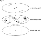
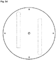
- Fig. 3a to Fig. 3d illustrate each layer of the rotatable platform 10 containing the microfluidic structure 20 of Fig. 1 .
- the rotatable platform 10 containing the microfluidic structure 20 can be composed of three layers, an upper layer part ( Fig. 3b ), a middle layer part ( Fig. 3c ) and a lower layer part ( Fig. 3d ).
- Each component of the microfluidic structure 20 except the detection part 120 can be formed by a patterning process using micro milling.
- the first part 110a of the first microfluidic channel 110 is disposed in the middle layer part, and the first part 110a includes a part connected to the sample injection part 100 and a bending part 111.
- the second part 110b of the first microfluidic channel 110 is disposed in the upper layer part, and the second part 110b includes a part connected to the detection part 120.
- the fluidic sample containing DNPH-derivatized multiple aldehydes and/or ketones is injected from the first microfluidic channel 110 located in the upper layer part of the rotatable platform 10 to the detection part 120 inserted in the middle layer part and the lower layer part of the rotatable platform 10, i.e., in a downward.
- the fluidic sample can be developed more uniformly on the detection part 120.
- the first part 140a of the second microfluidic channel 140 is disposed in the middle layer part, and the first part 140a includes a part connected to the eluent introduction part 130 and bending parts 141, 142.
- the second part 140b of the second microfluidic channel 140 is disposed over the upper layer part and the middle layer part, and the second part 140b includes a part connected to the detection part 120. This is to allow the eluent to be introduced into the bottom center of the detection part 120.
- the upper layer part includes an inlet 100a of the sample injection part 100 and an inlet 130a of the eluent introduction part 130.
- the inlet 100a of the sample injection part 100 and the inlet 130a of the eluent introduction part 130 are formed over the upper layer part and the middle layer part.
- the sample and the eluent are injected into the inlet 100a of the sample injection part 100 and the inlet 130a of the eluent introduction part 130 provided above the rotatable platform 10 (i.e., the upper layer part), respectively, the sample and the eluent are accommodated in the injection part 100 and the eluent introduction part 130 provided in the middle layer, respectively.
- a space that corresponds to the shape of the detection part 120 across the middle layer part and the lower layer part and into which the detection part 120 can be inserted, and the reserve area 150 through which one end of the detection part 120 can be inserted are provided.
- the middle layer part is opened to allow the detection part 120 to be inserted, and the lower layer part is provided with a concave portion that corresponds to the shape of the detection part 120 and in which the detection part 120 can be inserted.
- the detection part 120 can be disposed over the middle layer part and the lower layer part.
- the reserve area 150 is provided so that one end of the detection part 120 can be inserted over the middle layer part and the lower layer part.
- the present invention is not limited to the above description, and various modifications and changes are possible, for examples, the part where the detection part 120 is disposed in the upper layer part may be provided with a concave portion corresponding to the shape of the detection part 120 at the lower surface of the upper layer part so that the detection part 120 can be inserted.
- Materials of the upper layer part, the middle layer part and the lower layer part may include, for example, polycarbonate (PC) or polymethylmethacrylate (PMMA) and the like.
- an adhesive layer (not shown) is provided between the upper layer part, the middle layer part and the lower layer part to bond the upper layer part and the middle layer part, and the middle layer part and the lower layer part.
- the adhesive layer can be, for example, made of an acryl-based double-sided adhesive tape.
- a tape of a plate made of a material having an adhesive component corresponding to the size of the rotatable platform 10 the regions corresponding to the above-described components of each layer part can be removed by, for example, cutting.
- the region corresponding to the inlet 100a of the sample injection part 100 and the inlet 130a of the eluent introduction part 130 may be cut so that the sample and the eluent injected through the inlet 100a of the sample injection part 100 and the inlet 130a of the eluent introduction part 130 of the upper layer part, respectively, can move to the middle layer part.
- the regions corresponding to the components of the middle layer part and the lower layer part may be cut.
- the fluidic sample containing aldehydes and/or ketones can move from the sample injection part 100 to the first microfluidic channel 110 and then to the detection part 120.
- the eluent can move from the eluent introduction part 130 to the second microfluidic channel 140 and then to the detection part 120.
- the fluidic sample containing aldehydes and/or ketones is injected into the sample injection part 100
- the detecting device 1 when the detecting device 1 is rotated firstly at 3500 RPM for 20 seconds, the sample injected into the inlet 100a of the sample injection part 100 moves to a rear end part 100c of the sample injection part 100, and upon stopping of the detecting device 1 after the first rotation, the fluidic sample containing aldehydes and/or ketones moves from the rear end part 100c of the sample injection part 100 to the first microfluidic channel 110 by the capillary force.
- the eluent injected into the inlet 130a of the eluent introduction part 130 moves to the rear end part 130c of the eluent introduction part 130, and upon stopping of the detecting device 1 after the first rotation, the eluent moves to the first bending part 141 of the second microfluidic channel 140 by the capillary force.
- the detecting device 1 rotates secondly at 3500 RPM for 20 seconds, the sample is introduced from the first microfluidic channel 110 to the detection part 120. Upon stopping of the detecting device 1 after the second rotation, the eluent moves to the second bending part 142 of the second microfluidic channel.
- the third rotation of the detecting device 1 proceeds at 1500 RPM for 20 seconds, the eluent is loaded on the reserve area 150, and after the third rotation of the detecting device 1 is stopped, the fluidic sample containing aldehydes and/or ketones is developed on the detection part 120 by the capillary force of the eluent.
- Fig. 4 illustrates the system for detecting aldehydes and/or ketones 2 comprising the device for detecting aldehydes and/or ketones 1 according to the present invention.
- the system for detecting aldehydes and/or ketones 2 further comprises a UV lamp (not shown).
- the UV lamp may be installed, for example, on the underside of the ceiling part of the system for detecting aldehydes and/or ketones 2.
- the present invention is not limited thereto, and the position where the UV lamp can be installed can be variously modified and changed as long as the aldehydes and/or ketones sample developed on the detection part 120 can be visually confirmed by the irradiating the detection part 120 using the UV lamp.
- the aldehydes and/or ketones do not contain a chromophore
- the DNP-derivatized aldehydes and/or ketones is developed on the detection part 120 after DNP derivatization in the sample injection part 100, and when the detection part 120 where the DNPH-derivatized aldehydes and/or ketones are developed is irradiated with the UV lamp, the aldehydes and/or ketones can be separated and detected visually.
- a plurality of aldehydes and/or ketones such as acetaldehyde, acetone, acrolein, benzaldehyde, butyraldehyde, formaldehyde and propionaldehyde can be qualitatively analyzed within 5 minutes. Since the seven kinds of aldehydes and/or ketones contained in the fluidic sample are developed differently on the detection part 120, the seven kinds of aldehydes and/or ketones developed on the detection part 120 can be detected, respectively, by irradiating the UV lamp 30 to the detection part 120.
- the DNPH derivatization of the aldehydes and/or ketones and their development on the detection part is accomplished by controlling the centrifugal force and capillary force by rotation control of the rotatable platform 10 on which the microfluidic structure 20 is placed.
- the detecting device 1 it is possible to economically and rapidly separate and detect the multiple aldehydes and/or ketones.
- the device is more economical than the conventional expensive HPLC analysis equipment and can shorten the time required for analysis. Further, the device can be applied quickly and conveniently in the field where separation and detection of the multiple aldehydes and/or ketones is required. Moreover, if multiple samples are present and each of these samples contains different compositions of aldehydes and/or ketones, the multiple samples can be analyzed simultaneously in one device 1.
Landscapes
- Chemical & Material Sciences (AREA)
- Health & Medical Sciences (AREA)
- Physics & Mathematics (AREA)
- Analytical Chemistry (AREA)
- General Health & Medical Sciences (AREA)
- Life Sciences & Earth Sciences (AREA)
- Immunology (AREA)
- Biochemistry (AREA)
- General Physics & Mathematics (AREA)
- Pathology (AREA)
- Spectroscopy & Molecular Physics (AREA)
- Hematology (AREA)
- Clinical Laboratory Science (AREA)
- Chemical Kinetics & Catalysis (AREA)
- Dispersion Chemistry (AREA)
- Engineering & Computer Science (AREA)
- Biomedical Technology (AREA)
- Urology & Nephrology (AREA)
- Molecular Biology (AREA)
- Microbiology (AREA)
- Cell Biology (AREA)
- Biotechnology (AREA)
- Food Science & Technology (AREA)
- Medicinal Chemistry (AREA)
- Automatic Analysis And Handling Materials Therefor (AREA)
- Optical Measuring Cells (AREA)
- Investigating Or Analyzing Non-Biological Materials By The Use Of Chemical Means (AREA)
Abstract
Description
- The present application claims the benefits of priority to Korean Patent Application No.
10-2018-0072922, filed on June 25, 2018 - The present invention relates to a device and a system for detecting aldehydes or ketones, and more specifically, to a device and a system for detecting aldehydes or ketones using a rotatable platform.
- Generally, aldehyde has no chromophore and UV detection is impossible. Therefore, it is common to conduct derivatization with an acetyl acetone reagent or a 2,4-dinitrophenylhydrazine (DNPH) reagent and then to detect the aldehyde using High Performance Liquid Chromatography (HPLC). The method using acetyl acetone is a derivatization method wherein the acetyl acetone selectively reacts with formaldehyde, and the method using DNPH is a method of analyzing DNPH derivatives produced by the reaction between carbonyl compounds and DNPH by reacting with the carbonyl compounds. For aldehydes and ketones existing in the air, commercially available DNPH cartridges are used. Since conventional methods require expensive equipment and skilled analytical techniques, it is difficult to perform analysis of aldehydes or ketones quickly and simply in the field.
- It is required to develop an economical and cost-effective color development-based aldehydes and/or ketones analysis system for the replacement of an expensive aldehydes and/or ketones analysis equipment, and it is required to develop a miniaturized analysis system that can be conveniently applied in the field.
- Further, it is required to develop a system capable of simultaneously detecting a plurality of samples including aldehydes and/or ketones and reducing the analysis time.
- The device for detecting aldehydes or ketones according to the present invention may comprise:
- a disk-shaped rotatable platform; and
- a microfluidic structure disposed on the rotatable platform, which may comprise:
- a sample injection part where a fluidic sample containing the aldehydes or ketones is injected and the aldehydes or ketones can be subjected to DNPH derivatization;
- a first microfluidic channel (siphon channel) that is a passage through which the sample can move to a detection part and connects the sample injection part and the detection part;
- an eluent introduction part into which an eluent can be injected;
- a second microfluidic channel that is a passage through which the eluent can move to the detection part and connects the eluent introduction part and the detection part; and
- a detection part coated with a substance capable of causing reaction with the aldehydes or ketones of the sample so that the aldehydes or ketones of the sample can be separated and developed with the eluent,
- Further, in the device for detecting aldehydes or ketones according to the present invention, the aldehydes or ketones which can be contained in the sample may be at least one selected from the group consisting of acetaldehyde, acetone, acrolein, benzaldehyde, butyraldehyde, formaldehyde and propionaldehyde.
- Further, in the device for detecting aldehydes or ketones according to the present invention, the inside of the sample injection part may be filled with 2,4-DNPH coated silica in the form of beads.
- Further, in the device for detecting aldehydes or ketones according to the present invention, the microfluidic structure may be provided in a plurality, and the plurality of microfluidic structures can accommodate different fluidic samples, respectively, and may be disposed radially symmetrically on the rotatable platform.
- Further, in the device for detecting aldehydes or ketones according to the present invention, the microfluidic structure may comprise a reserve area connecting the second microfluidic channel and the detection part, and one end of the detection part may be accommodated in the reserve area.
- Further, in the device for detecting aldehydes or ketones according to the present invention, the microfluidic structure may further comprise: a first air circulation channel connecting the sample injection part and the other end of the detection part; and a second air circulation channel connecting the eluent introduction part and the other end of the detection part, wherein the first air circulation channel and the second air circulation channel may increase the evaporation rate of the fluidic sample and the eluent in the detection part and prevent moisture condensation in the detection part.
- Further, in the device for detecting aldehydes or ketones according to the present invention, the first microfluidic channel and the second microfluidic channel may comprise bending parts, respectively, and the number of the bending part of the second microfluidic channel may be one more than the number of the bending part of the first microfluidic channel.
- Further, in the device for detecting aldehydes or ketones according to the present invention,
during the first rotation of the device, the injected fluidic sample may move to the rear end of the sample injection part, and the injected eluent may move to the rear end of the eluent introduction part;
upon stopping the device after the first rotation of the device, the sample may move from the sample injection part to the first microfluidic channel, and the eluent may move from the eluent introduction part to the first bending part of the second microfluidic channel;
during the second rotation of the device, the sample may be introduced from the first microfluidic channel to the detection part;
upon stopping the device after the second rotation of the device, the eluent may move from the first bending part of the second microfluidic channel to the second bending part of the second microfluidic channel;
during the third rotation of the device, the eluent may be introduced from the second microfluidic channel to the reserve area; and
upon stopping the device after the third rotation of the device, the sample may be developed on the detection part by the eluent. - Further, a system for detecting aldehydes or ketones comprising: the device for detecting aldehydes or ketones according to the present invention, and a UV lamp for visually observing the aldehydes or ketones separated and developed on the detection part by irradiating UV to the detection part may be provided.
- According to the present invention, it is possible to provide an economical and cost-effective color development-based aldehydes or ketones analysis system as compared with an expensive HPLC which is a conventional aldehydes or ketones analysis equipment, and also to provide a miniaturized analysis system that can be conveniently applied in the field.
- Further, according to the present invention, there is an advantage that it is possible to perform analysis by detecting a plurality of samples including aldehydes or ketones simultaneously, thereby shortening the analysis time.
-
-
Fig. 1 illustrates the device for detection according to one embodiment of the present invention. -
Fig. 2 illustrates a microfluidic structure of the device for detection ofFig. 1 . -
Fig. 3a to Fig. 3d illustrate each layer of a rotatable platform comprising a microfluidic structure. -
Fig. 4 illustrates a qualitative analytic system comprising the device for detection according to the present invention and capable of rotating the device. - Various changes in form and details may be made to the presently disclosed embodiment and thus should not be construed as being limited to the aspects set forth herein. The presently disclosed embodiment is not limited to the aspects described in the present description, and thus it should be understood that the presently disclosed embodiment includes every kind of variation example or alternative equivalent included in the spirit and scope of the presently disclosed embodiment. Also, while describing the aspects, detailed descriptions about related well-known functions or configurations that may diminish the clarity of the points of the aspects of the presently disclosed embodiment will be omitted.
- The device for detecting aldehydes or ketones according to the present invention may comprise:
- a disk-shaped rotatable platform; and
- a microfluidic structure disposed on the rotatable platform, which may comprise:
- a sample injection part where a fluidic sample containing the aldehydes or ketones is injected and the aldehydes or ketones can be subjected to DNPH derivatization;
- a first microfluidic channel (siphon channel) that is a passage through which the sample can move to a detection part and connects the sample injection part and the detection part;
- an eluent introduction part into which an eluent can be injected;
- a second microfluidic channel that is a passage through which the eluent can move to the detection part and connects the eluent introduction part and the detection part; and
- a detection part coated with a substance capable of causing reaction with the aldehydes or ketones of the sample so that the aldehydes or ketones of the sample can be separated and developed with the eluent,
- Further, in the device for detecting aldehydes or ketones according to the present invention, the aldehydes or ketones which can be contained in the sample may be at least one selected from the group consisting of acetaldehyde, acetone, acrolein, benzaldehyde, butyraldehyde, formaldehyde and propionaldehyde.
- Further, in the device for detecting aldehydes or ketones according to the present invention, the inside of the sample injection part may be filled with 2,4-DNPH coated silica in the form of beads.
- Further, in the device for detecting aldehydes or ketones according to the present invention, the microfluidic structure may be provided in a plurality, and the plurality of microfluidic structures can accommodate different fluidic samples, respectively, and may be disposed radially symmetrically on the rotatable platform.
- Further, in the device for detecting aldehydes or ketones according to the present invention, the microfluidic structure may comprise the reserve area connecting the second microfluidic channel and the detection part, and one end of the detection part may be accommodated in the reserve area.
- Further, in the device for detecting aldehydes or ketones according to the present invention, the microfluidic structure may further comprise: a first air circulation channel connecting the sample injection part and the other end of the detection part; and a second air circulation channel connecting the eluent introduction part and the other end of the detection part, wherein the first air circulation channel and the second air circulation channel may increase the evaporation rate of the fluidic sample and the eluent in the detection part and may prevent moisture condensation in the detection part.
- Further, in the device for detecting aldehydes or ketones according to the present invention, the first microfluidic channel and the second microfluidic channel may comprise bending parts, respectively, and the number of the bending part of the second microfluidic channel may be one more than the number of the bending part of the first microfluidic channel.
- Further, in the device for detecting aldehydes or ketones according to the present invention,
during the first rotation of the device, the injected fluidic sample may move to the rear end of the sample injection part, and the injected eluent may move to the rear end of the eluent introduction part;
upon stopping the device after the first rotation of the device, the sample may move from the sample injection part to the first microfluidic channel, and the eluent may move from the eluent introduction part to the first bending part of the second microfluidic channel;
during the second rotation of the device, the sample may be introduced from the first microfluidic channel to the detection part;
upon stopping the device after the second rotation of the device, the eluent may move from the first bending part of the second microfluidic channel to the second bending part of the second microfluidic channel;
during the third rotation of the device, the eluent may be introduced from the second microfluidic channel to the reserve area; and
upon stopping the device after the third rotation of the device, the sample may be developed on the detection part by the eluent. - Further, a system for detecting aldehydes or ketones comprising: the device for detecting aldehydes or ketones according to the present invention, and a UV lamp for visually observing the aldehydes or ketones separated and developed on the detection part by irradiating UV to the detection part can be provided.
- Hereinafter, the device for detecting aldehydes or ketones using a rotatable disk system according to the present invention will be explained in detail. The accompanying drawings are provided for illustration only and should not be construed as limiting the scope of the invention.
- In addition, the same or corresponding components are given by the same or similar reference numerals, regardless of the reference numerals in the drawings, for which the repeated explanation will be omitted, and for convenience of description, the size and shape of each illustrated structural member may be exaggerated or downsized.
-
Fig. 1 illustrates the device for detecting aldehydes and/orketones 1 according to one embodiment of the present invention, andFig. 2 illustrates amicrofluidic structure 20 of the rotatable disk system ofFig. 1 . - First, referring to
Fig. 1 , the device for detecting aldehydes and/orketones 1 comprises arotatable platform 10 and amicrofluidic structure 20 equipped in therotatable platform 10. Therotatable platform 10 may be, for example, a circular disk, and its size may be, for example, 14 cm to 17 cm in diameter. - The
rotatable platform 10 contains themicrofluidic structure 20. Therotatable platform 10 may contain onemicrofluidic structure 20, or a plurality ofmicrofluidic structures 20. The plurality ofmicrofluidic structures 20 is disposed radially symmetrically on therotatable platform 10. For example,Fig 1 illustrates the case that twomicrofluidic structures 20 are disposed on therotatable platform 10. Depending on the various circumstances in which the present invention is implemented, such as the size of therotatable platform 10 and the plurality ofmicrofluidic structures 20, three, four, five, six or more microfluidic structures can be disposed. - Referring to
Fig. 2, Fig. 2 illustrates themicrofluidic structure 20 of each of the plurality ofmicrofluidic structures 20. Themicrofluidic structure 20 comprises: asample injection part 100 where a fluidic sample containing the aldehydes or ketones is injected and a first microfluidic channel (siphon channel) 110 that is a passage through which the fluidic sample can move from thesample injection part 100 to adetection part 120, thedetection part 120 that can separate and detect multiple aldehydes or ketones contained in the fluidic sample, aneluent introduction part 130, a secondmicrofluidic channel 140 that is a passage through which the eluent can move from theeluent introduction part 130 to thedetection part 120, and areserve area 150 that connects the secondmicrofluidic channel 140 and thedetection part 120. - The
microfluidic structure 20 can accommodate the fluidic samples containing a plurality of aldehydes and/or ketones and then can separate and detect the aldehydes and/or ketones. The aldehydes and/or ketones that can be contained in the fluidic sample may be, for example, at least one selected from the group consisting of acetaldehyde, acetone, acrolein, benzaldehyde, butyraldehyde, formaldehyde and propionaldehyde. - The
sample injection part 100 has space to accommodate the fluidic sample containing aldehydes and/or ketones and contains aninlet 100a through which the fluidic sample can be injected into the space. In thesample injection part 100, 2,4-DNPH coated silica may be filled in the form of beads. Since aldehydes and/or ketones do not have a chromophore, the fluidic sample containing aldehydes and/or ketones is first subjected to DNPH derivatization in thesample injection part 100 before the fluidic sample containing aldehydes and/or ketones moves to thedetection part 120. - The
sample injection part 100 and thedetection part 120 can be connected to the firstmicrofluidic channel 110. Further, thesample injection part 100 can contain a blockingpart 100b. The blocking part serves to trap the sample in the inner space of thesample injection part 100 using difference in level of the channel so that when the sample is injected through theinlet 100a, the injected sample is prevented from flowing directly to the firstmicrofluidic channel 110. The blockingpart 100b is provided with an opening part for moving the sample from theinlet 100a to therear end part 100c of the sample injection part. By the first rotation of therotatable platform 10, the sample moves from theinlet 100a to therear end part 100c of the sample injection part. In thesample injection part 100, therear end part 100c of the sample injection part, i.e., the vicinity of where thesample injection part 100 is connected to the firstmicrofluidic channel 110, has a streamlined shape, for example. Accordingly, when the fluidic sample injected into thesample injection part 100 moves to the firstmicrofluidic channel 110, the resistance is minimized so that the fluidic sample injected into thesample injection part 100 can completely move to the firstmicrofluidic channel 110. - The first
microfluidic channel 110 contains a bendingpart 111. The bendingpart 111 contains, for example, a "U" shaped tube part. As will be described later, upon stopping the device for detecting aldehydes and/orketones 1 after the first rotation and before the second rotation of the detectingdevice 1, the fluidic sample containing DNPH-derivatized multiple aldehydes and/or ketones can move by the capillary force to the firstmicrofluidic channel 110, which is hydrophilic inside the channel. As a result, the fluidic sample can be accommodated in the channel of the firstmicrofluidic channel 110. - The end part of the first
microfluidic channel 110 is connected to thedetection part 120. The end part of the firstmicrofluidic channel 110 may be located near thereserve area 150 so that the sample is provided from the firstmicrofluidic channel 110 to thedetection part 120 and the sample can be developed on thedetection part 120 by the eluent provided in thereserve area 150 to be described later. However, the present invention is not limited to the above description, and various modifications are possible, for examples, the end part of the firstmicrofluidic channel 110 can be connected to a part accommodated in thereserve area 150 of thedetection part 120. - The
detection part 120 can be coated with a substance that can react with the aldehydes and/or ketones of the fluidic sample to develop the fluidic sample. Thedetection part 120 may be, for example, RP-18 F254s TLC plate wherein a substance in which C18 group is bonded to silica is coated on an aluminum support to a thickness of 0.2 mm. The detection part may be coated with fluorescent detectable F254s, and water can be used up to 40%. The size of thedetection part 120 may be, for example, 10 cm in length and 1 cm in width. Thisdetection part 120 may be applicable to a small amount (e.g., 0.5 µL) of sample. - The
eluent introduction part 130 has space to accommodate the eluent and the space contains aninlet 130a into which the eluent can be injected. Theeluent introduction part 130 and thedetection part 120 can be connected to the secondmicrofluidic channel 140. Further, theeluent introduction part 130 may contain a blockingpart 130b which serves to trap the sample in the inner space of theeluent introduction part 130 using difference in level of the channel so that when the sample is injected through theinlet 130a, the injected sample is prevented from flowing directly to the secondmicrofluidic channel 140. The blockingpart 130b is provided with an opening part for moving the eluent from theinlet 130a to therear end part 130c of the eluent introduction part. By the first rotation of therotatable platform 10, the eluent moves from theinlet 130a to therear end part 130c of the eluent introduction part. In theeluent introduction part 130, therear end part 130c of the eluent introduction part, i.e., the vicinity of where theeluent introduction part 130 is connected to the secondmicrofluidic channel 140, has a streamlined shape, for example. Accordingly, when the fluidic sample injected into theeluent introduction part 130 moves to the secondmicrofluidic channel 140, the resistance is minimized so that the fluidic sample injected into theeluent introduction part 130 can completely move to the secondmicrofluidic channel 140. - The second
microfluidic channel 140 contains at least two bendingparts parts parts microfluidic channel 140 is one more than the number of the bendingpart 111 of the firstmicrofluidic channel 110. This is because the sample is first introduced into thedetection part 120 through the firstmicrofluidic channel 110, and then the eluent is subsequently introduced into thedetection part 120 through the secondmicrofluidic channel 140. As will be described later, upon stopping therotatable platform 10 after the first rotation and before the second rotation of the detectingdevice 1, the eluent can move by the capillary force to the hydrophilic secondmicrofluidic channel 140. As a result, the eluent can be accommodated in the channel of the secondmicrofluidic channel 140. More specifically, after the first rotation and before the second rotation, the eluent moves from theeluent introduction part 130 to thefirst bending part 141. Then, after the second rotation, the eluent moves from thefirst bending part 141 to thesecond bending part 142. - Further, the device for detecting aldehydes and/or
ketones 1 contains areserve area 150 at the end where the secondmicrofluidic channel 140 is connected to thedetection part 120, and one end of thedetection part 120 is accommodated in thereserve area 150. Thereserve area 150 is a concavely patterned area in the middle layer part and the bottom layer part of the rotatable platform 10 (see,Fig. 3a ,Fig. 3c ,Fig. 3d ), respectively, so as to accommodate the eluent therein. After the first rotation of therotatable platform 10, the eluent accommodated in the secondmicrofluidic channel 140 moves from the secondmicrofluidic channel 140 to thereserve area 150 during the third rotation of therotatable platform 10, and at this time, the centrifugal force due to the rotation causes the eluent to be remained (i.e., trapped) in thereserve area 150 without being developed to thedetection part 120. Upon stopping the third rotation of therotatable platform 10, the eluent is developed to thedetection part 120 connected to thereserve area 150, and the sample first introduced into thedetection part 120 by the eluent is developed on thedetection part 120 together. - Further, the device for detecting aldehydes and/or
ketones 1 comprises the firstair circulation channel 160 and the secondair circulation channel 170. The firstair circulation channel 160 connects between thesample injection part 100 and the other end part of thedetection part 120. Accordingly, the components are connected in such a way that air circulates in the order of the sample injection part 100 - the first microfluidic channel 110 - the detection part 120 - the first air circulation channel 140- thesample injection part 100. In the same manner, the secondair circulation channel 170 connects between theeluent introduction part 130 and the other end part of thedetection part 120. Accordingly, the components are connected in such a way that air circulates in the order of the eluent introduction part 130 - the second microfluidic channel 140 - the reserve area 150 - the detection part 120 - the second air circulation channel 140 - theeluent introduction part 130. - By introducing the first
air circulation channel 160 and the secondair circulation channel 170, the evaporation rate of the fluidic sample and the eluent in thedetection part 120 is increased while the moisture condensation in thedetection part 120 is prevented. A capillary valve is formed by air pressure by drilling a hole with a thickness of about 1 mm and a diameter of about 0.8 mm at each of the points where thesample injection part 100 and the firstair circulation channe 140 are connected and theeluent introduction part 130 and the secondair circulation channel 170 are connected, so that backflow of the sample and the eluent to the firstair circulation channel 160 and the secondair circulation channel 170 can be prevented. -
Fig. 3a to Fig. 3d illustrate each layer of therotatable platform 10 containing themicrofluidic structure 20 ofFig. 1 . As shown inFig. 3a , therotatable platform 10 containing themicrofluidic structure 20 can be composed of three layers, an upper layer part (Fig. 3b ), a middle layer part (Fig. 3c ) and a lower layer part (Fig. 3d ). Each component of themicrofluidic structure 20 except thedetection part 120 can be formed by a patterning process using micro milling. - First, referring to
Fig. 3a to Fig. 3c , thefirst part 110a of the firstmicrofluidic channel 110 is disposed in the middle layer part, and thefirst part 110a includes a part connected to thesample injection part 100 and a bendingpart 111. Thesecond part 110b of the firstmicrofluidic channel 110 is disposed in the upper layer part, and thesecond part 110b includes a part connected to thedetection part 120. This is to provide the sample in a manner that the sample falls down from the top of thedetection part 120 in a downward direction, i.e., onto thedetection part 120 when the sample is provided from the firstmicrofluidic channel 110 to thedetection part 120 after the sample is accommodated in thefirst part 110a of the firstmicrofluidic channel 110 from thesample injection part 100 disposed in the middle layer. Accordingly, the sample can be developed more uniformly on thedetection part 120. - The fluidic sample containing DNPH-derivatized multiple aldehydes and/or ketones is injected from the first
microfluidic channel 110 located in the upper layer part of therotatable platform 10 to thedetection part 120 inserted in the middle layer part and the lower layer part of therotatable platform 10, i.e., in a downward. Thus, the fluidic sample can be developed more uniformly on thedetection part 120. - Further, referring to
Fig. 3a to Fig. 3c , thefirst part 140a of the secondmicrofluidic channel 140 is disposed in the middle layer part, and thefirst part 140a includes a part connected to theeluent introduction part 130 and bendingparts second part 140b of the secondmicrofluidic channel 140 is disposed over the upper layer part and the middle layer part, and thesecond part 140b includes a part connected to thedetection part 120. This is to allow the eluent to be introduced into the bottom center of thedetection part 120. - Further, as shown in
Fig. 3b , the upper layer part includes aninlet 100a of thesample injection part 100 and aninlet 130a of theeluent introduction part 130. As shown inFig. 3b andFig. 3c , theinlet 100a of thesample injection part 100 and theinlet 130a of theeluent introduction part 130 are formed over the upper layer part and the middle layer part. Thus, when the sample and the eluent are injected into theinlet 100a of thesample injection part 100 and theinlet 130a of theeluent introduction part 130 provided above the rotatable platform 10 (i.e., the upper layer part), respectively, the sample and the eluent are accommodated in theinjection part 100 and theeluent introduction part 130 provided in the middle layer, respectively. - In the middle layer part, most of the components described above with reference to
Fig. 1 andFig. 2 are disposed. Therefore, the description overlapping with the components described inFig. 1 andFig. 2 with respect to the middle layer part will be described with reference toFig. 1 andFig. 2 described above. - Referring to
Fig. 3c andFig. 3d , a space that corresponds to the shape of thedetection part 120 across the middle layer part and the lower layer part and into which thedetection part 120 can be inserted, and thereserve area 150 through which one end of thedetection part 120 can be inserted are provided. The middle layer part is opened to allow thedetection part 120 to be inserted, and the lower layer part is provided with a concave portion that corresponds to the shape of thedetection part 120 and in which thedetection part 120 can be inserted. Thedetection part 120 can be disposed over the middle layer part and the lower layer part. Further, thereserve area 150 is provided so that one end of thedetection part 120 can be inserted over the middle layer part and the lower layer part. However, the present invention is not limited to the above description, and various modifications and changes are possible, for examples, the part where thedetection part 120 is disposed in the upper layer part may be provided with a concave portion corresponding to the shape of thedetection part 120 at the lower surface of the upper layer part so that thedetection part 120 can be inserted. - Materials of the upper layer part, the middle layer part and the lower layer part may include, for example, polycarbonate (PC) or polymethylmethacrylate (PMMA) and the like.
- On the other hand, an adhesive layer (not shown) is provided between the upper layer part, the middle layer part and the lower layer part to bond the upper layer part and the middle layer part, and the middle layer part and the lower layer part. The adhesive layer can be, for example, made of an acryl-based double-sided adhesive tape. In a tape of a plate made of a material having an adhesive component corresponding to the size of the
rotatable platform 10, the regions corresponding to the above-described components of each layer part can be removed by, for example, cutting. - For example, in the adhesive layer bonding the upper layer part and the middle layer part, the region corresponding to the
inlet 100a of thesample injection part 100 and theinlet 130a of theeluent introduction part 130 may be cut so that the sample and the eluent injected through theinlet 100a of thesample injection part 100 and theinlet 130a of theeluent introduction part 130 of the upper layer part, respectively, can move to the middle layer part. Further, in the adhesive layer bonding the middle layer part and the lower layer part, as shown inFig. 3a , the regions corresponding to the components of the middle layer part and the lower layer part may be cut. - According to the detecting
device 1 according to the present invention, by controlling the rotation of the device for detecting aldehydes and/orketones 1, the fluidic sample containing aldehydes and/or ketones can move from thesample injection part 100 to the firstmicrofluidic channel 110 and then to thedetection part 120. Likewise, the eluent can move from theeluent introduction part 130 to the secondmicrofluidic channel 140 and then to thedetection part 120. - For example, after the fluidic sample containing aldehydes and/or ketones is injected into the
sample injection part 100, when the detectingdevice 1 is rotated firstly at 3500 RPM for 20 seconds, the sample injected into theinlet 100a of thesample injection part 100 moves to arear end part 100c of thesample injection part 100, and upon stopping of the detectingdevice 1 after the first rotation, the fluidic sample containing aldehydes and/or ketones moves from therear end part 100c of thesample injection part 100 to the firstmicrofluidic channel 110 by the capillary force. Further, during the first rotation, the eluent injected into theinlet 130a of theeluent introduction part 130 moves to therear end part 130c of theeluent introduction part 130, and upon stopping of the detectingdevice 1 after the first rotation, the eluent moves to thefirst bending part 141 of the secondmicrofluidic channel 140 by the capillary force. - Again, when the detecting
device 1 rotates secondly at 3500 RPM for 20 seconds, the sample is introduced from the firstmicrofluidic channel 110 to thedetection part 120. Upon stopping of the detectingdevice 1 after the second rotation, the eluent moves to thesecond bending part 142 of the second microfluidic channel. - When the third rotation of the detecting
device 1 proceeds at 1500 RPM for 20 seconds, the eluent is loaded on thereserve area 150, and after the third rotation of the detectingdevice 1 is stopped, the fluidic sample containing aldehydes and/or ketones is developed on thedetection part 120 by the capillary force of the eluent. -
Fig. 4 illustrates the system for detecting aldehydes and/or ketones 2 comprising the device for detecting aldehydes and/orketones 1 according to the present invention. The system for detecting aldehydes and/or ketones 2 further comprises a UV lamp (not shown). The UV lamp may be installed, for example, on the underside of the ceiling part of the system for detecting aldehydes and/or ketones 2. However, the present invention is not limited thereto, and the position where the UV lamp can be installed can be variously modified and changed as long as the aldehydes and/or ketones sample developed on thedetection part 120 can be visually confirmed by the irradiating thedetection part 120 using the UV lamp. As described above, since the aldehydes and/or ketones do not contain a chromophore, the DNP-derivatized aldehydes and/or ketones is developed on thedetection part 120 after DNP derivatization in thesample injection part 100, and when thedetection part 120 where the DNPH-derivatized aldehydes and/or ketones are developed is irradiated with the UV lamp, the aldehydes and/or ketones can be separated and detected visually. - Like this, by using the detecting
device 1 according to the present invention, a plurality of aldehydes and/or ketones such as acetaldehyde, acetone, acrolein, benzaldehyde, butyraldehyde, formaldehyde and propionaldehyde can be qualitatively analyzed within 5 minutes. Since the seven kinds of aldehydes and/or ketones contained in the fluidic sample are developed differently on thedetection part 120, the seven kinds of aldehydes and/or ketones developed on thedetection part 120 can be detected, respectively, by irradiating the UV lamp 30 to thedetection part 120. - According to the present invention, the DNPH derivatization of the aldehydes and/or ketones and their development on the detection part is accomplished by controlling the centrifugal force and capillary force by rotation control of the
rotatable platform 10 on which themicrofluidic structure 20 is placed. - Further, by using the detecting
device 1 according to one embodiment of the present invention, it is possible to economically and rapidly separate and detect the multiple aldehydes and/or ketones. The device is more economical than the conventional expensive HPLC analysis equipment and can shorten the time required for analysis. Further, the device can be applied quickly and conveniently in the field where separation and detection of the multiple aldehydes and/or ketones is required. Moreover, if multiple samples are present and each of these samples contains different compositions of aldehydes and/or ketones, the multiple samples can be analyzed simultaneously in onedevice 1. - It should be understood that those skilled in the art can carry out other modifications without changing its technical spirit or essential features. Therefore, the above-described embodiment of the present invention is merely exemplary in all aspects and should not be construed to be limited, and it should be understood that the scope of the present invention is defined by the following claims and the meanings and ranges of the claims and all modifications and changed forms derived from their equivalents pertain to the scope of the present invention.
-
- 1:
- Device for detecting aldehydes and/or ketones
- 2:
- Analysis system for detecting aldehydes and/or ketones
- 10:
- Rotatable platform
- 20:
- Microfluidic structure
- 100:
- Sample injection part
- 110:
- First microfluidic channel
- 120:
- Detection part
- 130:
- Eluent introduction part
- 140:
- Second microfluidic channel
- 150:
- Reserve area
- 160:
- First air circulation channel
- 170:
- Second air circulation channel
Claims (9)
- A device for detecting aldehydes or ketones comprising:a disk-shaped rotatable platform; anda microfluidic structure disposed on the rotatable platform, which comprises:a sample injection part where a fluidic sample containing the aldehydes or ketones is injected and the aldehydes or ketones can be subjected to DNPH derivatization;a first microfluidic channel (siphon channel) that is a passage through which the fluidic sample can move to a detection part and connects the sample injection part and the detection part;an eluent introduction part into which an eluent can be injected;a second microfluidic channel that is a passage through which the eluent can move to the detection part and connects the eluent introduction part and the detection part; andthe detection part coated with a substance capable of causing reaction with the aldehydes or ketones of the fluidic sample so that the aldehydes or ketones of the fluidic sample can be separated and developed with the eluent,wherein upon rotation of the rotatable platform, the aldehydes or ketones injected into the sample injection part are subjected to DNPH derivatization.
- The device for detecting aldehydes or ketones according to claim 1, wherein the aldehydes or ketones which can be contained in the fluidic sample is at least one selected from the group consisting of acetaldehyde, acetone, acrolein, benzaldehyde, butyraldehyde, formaldehyde and propionaldehyde.
- The device for detecting aldehydes or ketones according to claim 1, wherein the inside of the sample injection part is filled with 2,4-DNPH coated silica in the form of beads.
- The device for detecting aldehydes or ketones according to claim 1, wherein the microfluidic structure is provided in a plurality, and
the plurality of microfluidic structures can accommodate different fluidic samples, respectively, and are disposed radially symmetrically on the rotatable platform. - The device for detecting aldehydes or ketones according to claim 1, wherein the microfluidic structure comprises a reserve area connecting the second microfluidic channel and the detection part, and one end of the detection part is accommodated in the reserve area.
- The device for detecting aldehydes or ketones according to claim 5, wherein the microfluidic structure further comprises:a first air circulation channel connecting the sample injection part and the other end of the detection part; anda second air circulation channel connecting the eluent introduction part and the other end of the detection part,wherein the first air circulation channel and the second air circulation channel increase the evaporation rate of the fluidic sample and the eluent in the detection part and prevent moisture condensation in the detection part.
- The device for detecting aldehydes or ketones according to claim 1, wherein the first microfluidic channel and the second microfluidic channel comprises bending parts, respectively,
and the number of the bending part of the second microfluidic channel is one more than the number of the bending part of the first microfluidic channel. - The device for detecting aldehydes or ketones according to claim 5, wherein during a first rotation of the device, the injected fluidic sample moves to a rear end of the sample injection part, and the injected eluent moves to a rear end of the eluent introduction part;
upon stopping the device after the first rotation of the device, the fluidic sample moves from the sample injection part to the first microfluidic channel, and the eluent moves from the eluent introduction part to a first bending part of the second microfluidic channel;
during a second rotation of the device, the fluidic sample is introduced from the first microfluidic channel to the detection part;
upon stopping the device after the second rotation of the device, the eluent moves from the first bending part of the second microfluidic channel to a second bending part of the second microfluidic channel;
during a third rotation of the device, the eluent is introduced from the second microfluidic channel to the reserve area; and
upon stopping the device after the third rotation of the device, the fluidic sample is developed on the detection part by the eluent. - A system for detecting aldehydes or ketones comprising: the device for detecting aldehydes or ketones according to any one of claim 1 to claim 8, and a UV lamp for visually observing the aldehydes or ketones separated and developed on the detection part by irradiating UV to the detection part.
Applications Claiming Priority (2)
| Application Number | Priority Date | Filing Date | Title |
|---|---|---|---|
| KR1020180072922A KR102301178B1 (en) | 2018-06-25 | 2018-06-25 | A device for detecting Aldehyde/Ketone |
| PCT/KR2018/012426 WO2020004719A1 (en) | 2018-06-25 | 2018-10-19 | Microdevice for detecting aldehydes or ketones |
Publications (3)
| Publication Number | Publication Date |
|---|---|
| EP3686604A1 true EP3686604A1 (en) | 2020-07-29 |
| EP3686604A4 EP3686604A4 (en) | 2020-07-29 |
| EP3686604B1 EP3686604B1 (en) | 2022-07-20 |
Family
ID=68987130
Family Applications (1)
| Application Number | Title | Priority Date | Filing Date |
|---|---|---|---|
| EP18924573.1A Active EP3686604B1 (en) | 2018-06-25 | 2018-10-19 | Microdevice for detecting aldehydes or ketones |
Country Status (6)
| Country | Link |
|---|---|
| US (1) | US11484880B2 (en) |
| EP (1) | EP3686604B1 (en) |
| JP (1) | JP6875046B2 (en) |
| KR (1) | KR102301178B1 (en) |
| CN (1) | CN111316107B (en) |
| WO (1) | WO2020004719A1 (en) |
Families Citing this family (1)
| Publication number | Priority date | Publication date | Assignee | Title |
|---|---|---|---|---|
| KR102463382B1 (en) | 2019-04-19 | 2022-11-03 | 주식회사 엘지화학 | Device for detecting Aldehyde/Ketone |
Family Cites Families (22)
| Publication number | Priority date | Publication date | Assignee | Title |
|---|---|---|---|---|
| US6342349B1 (en) | 1996-07-08 | 2002-01-29 | Burstein Technologies, Inc. | Optical disk-based assay devices and methods |
| JPH11101791A (en) * | 1997-07-30 | 1999-04-13 | Wako Pure Chem Ind Ltd | Analysis of aldehyde |
| JP2001174408A (en) | 1999-12-22 | 2001-06-29 | Firmware Technology Co Ltd | Method and apparatus for measuring formaldehyde |
| EP1849005A1 (en) * | 2005-01-17 | 2007-10-31 | Gyros Patent Ab | A method for detecting an at least bivalent analyte using two affinity reactants |
| JP2007205867A (en) * | 2006-02-01 | 2007-08-16 | Shinwa Kako Kk | Fiber-filled needle for analysis of aldehydes and ketones and analyzing apparatus and method |
| KR100818274B1 (en) | 2006-09-05 | 2008-04-01 | 삼성전자주식회사 | Microfluidic system control device and method thereof, and microfluidic system |
| CN101113973A (en) | 2007-08-24 | 2008-01-30 | 湖南中烟工业公司 | A method for detecting volatile carbonyl compounds in cigarette filters by solid-phase extraction capillary gas chromatography |
| EP3869205B1 (en) * | 2008-01-21 | 2023-11-22 | Nexus Dx, Inc. | Thin-film layered centrifuge device and analysis method using the same |
| KR101099495B1 (en) * | 2008-10-14 | 2011-12-28 | 삼성전자주식회사 | Centrifugal force-based microfluidic device, its manufacturing method and sample analysis method using the same |
| KR101722548B1 (en) * | 2010-01-29 | 2017-04-03 | 삼성전자주식회사 | Centrifugal Micro-fluidic Device and Method for detecting analytes from liquid specimen |
| KR20120080765A (en) * | 2011-01-10 | 2012-07-18 | 삼성전자주식회사 | Microfluidic device and analyte detection method using the same |
| CN103517762B (en) | 2011-03-24 | 2015-12-23 | 拜森菲特有限公司 | To the control of the liquid stream order of microfluidic device |
| KR101256474B1 (en) * | 2011-06-15 | 2013-04-23 | 국립대학법인 울산과학기술대학교 산학협력단 | Microfluidic device and mamufacturing method thereof, apparatus and method detecting specimen using the same |
| KR20140055528A (en) * | 2012-10-31 | 2014-05-09 | 삼성전자주식회사 | Microfluidic structure, microfluidic system and control method for microfluidic test device |
| KR20140148194A (en) | 2013-06-21 | 2014-12-31 | 삼성전기주식회사 | Real-time monitoring process fluid device and method for real time monitoring process using the same |
| CN103698458B (en) | 2013-12-26 | 2015-03-11 | 国家烟草质量监督检验中心 | Method for measuring main carbonyl compounds in main stream smoke of cigarette through ultra high performance convergence chromatography |
| KR20160018200A (en) * | 2014-08-08 | 2016-02-17 | 삼성전자주식회사 | Microfluidic device |
| CN105675894B (en) * | 2014-11-20 | 2017-10-20 | 绍兴普施康生物科技有限公司 | Gas type microfluidic test device and its operation method |
| KR101763510B1 (en) * | 2015-08-07 | 2017-08-01 | 한국과학기술원 | Microdevice integrated with ics and diagnosis method using the same |
| CN206441437U (en) | 2016-11-08 | 2017-08-25 | 安徽中医药高等专科学校 | A kind of microchip imparted knowledge to students for TLC |
| KR102594393B1 (en) | 2016-12-21 | 2023-10-27 | 엘지디스플레이 주식회사 | Organic light emitting display panel, organic light emitting display device |
| CN106872603B (en) | 2017-03-02 | 2019-11-08 | 国家烟草质量监督检验中心 | The high-performance liquid chromatogram determination method of formaldehyde and acetaldehyde in a kind of quick-fried pearl of cigarette filter |
-
2018
- 2018-06-25 KR KR1020180072922A patent/KR102301178B1/en active Active
- 2018-10-19 EP EP18924573.1A patent/EP3686604B1/en active Active
- 2018-10-19 WO PCT/KR2018/012426 patent/WO2020004719A1/en not_active Ceased
- 2018-10-19 JP JP2020524333A patent/JP6875046B2/en active Active
- 2018-10-19 US US16/763,094 patent/US11484880B2/en active Active
- 2018-10-19 CN CN201880072220.1A patent/CN111316107B/en active Active
Also Published As
| Publication number | Publication date |
|---|---|
| US11484880B2 (en) | 2022-11-01 |
| CN111316107A (en) | 2020-06-19 |
| JP2021501890A (en) | 2021-01-21 |
| JP6875046B2 (en) | 2021-05-19 |
| CN111316107B (en) | 2023-07-14 |
| KR20200000732A (en) | 2020-01-03 |
| WO2020004719A1 (en) | 2020-01-02 |
| EP3686604B1 (en) | 2022-07-20 |
| US20200360926A1 (en) | 2020-11-19 |
| EP3686604A4 (en) | 2020-07-29 |
| KR102301178B1 (en) | 2021-09-09 |
Similar Documents
| Publication | Publication Date | Title |
|---|---|---|
| EP2564207B1 (en) | Centrifugal micro-fluidic device and method for immunoassay | |
| EP2529220B1 (en) | Centrifugal micro-fluidic device and method for detecting analytes from liquid specimen | |
| US7390464B2 (en) | Fluidic circuits for sample preparation including bio-discs and methods relating thereto | |
| US20020076354A1 (en) | Apparatus and methods for separating components of particulate suspension | |
| US11635445B2 (en) | Device and method for qualitative and quantitative analysis of heavy metals utilizing rotary disc system | |
| US20070280859A1 (en) | Fluidic circuits for sample preparation including bio-discs and methods relating thereto | |
| CN110180611B (en) | Microfluidic chip assembly | |
| EP3686604B1 (en) | Microdevice for detecting aldehydes or ketones | |
| TW200521430A (en) | Fluidic circuits for sample preparation including bio-discs and methods relating thereto | |
| EP3809131B1 (en) | Rotary analysis system | |
| Vloemans et al. | Precise sample metering method by coordinated burst action of hydrophobic burst valves applied to dried blood spot collection | |
| US12090479B2 (en) | Method for detecting aldehydes or ketones | |
| KR102647283B1 (en) | A device for detecting Aldehyde/Ketone | |
| CN109070078A (en) | Analyte is measured with cylinder | |
| CN108572172B (en) | Detection device and detection method | |
| EP3809130B1 (en) | Microdevice for detecting aldehydes or ketones | |
| EP1503209A1 (en) | Chemical analyzer and gene diagnosing apparatus | |
| CN206960360U (en) | Paper box | |
| CN210206903U (en) | Microfluidic chip assembly |
Legal Events
| Date | Code | Title | Description |
|---|---|---|---|
| STAA | Information on the status of an ep patent application or granted ep patent |
Free format text: STATUS: THE INTERNATIONAL PUBLICATION HAS BEEN MADE |
|
| PUAI | Public reference made under article 153(3) epc to a published international application that has entered the european phase |
Free format text: ORIGINAL CODE: 0009012 |
|
| STAA | Information on the status of an ep patent application or granted ep patent |
Free format text: STATUS: REQUEST FOR EXAMINATION WAS MADE |
|
| 17P | Request for examination filed |
Effective date: 20200428 |
|
| A4 | Supplementary search report drawn up and despatched |
Effective date: 20200604 |
|
| AK | Designated contracting states |
Kind code of ref document: A1 Designated state(s): AL AT BE BG CH CY CZ DE DK EE ES FI FR GB GR HR HU IE IS IT LI LT LU LV MC MK MT NL NO PL PT RO RS SE SI SK SM TR |
|
| AX | Request for extension of the european patent |
Extension state: BA ME |
|
| DAV | Request for validation of the european patent (deleted) | ||
| DAX | Request for extension of the european patent (deleted) | ||
| STAA | Information on the status of an ep patent application or granted ep patent |
Free format text: STATUS: EXAMINATION IS IN PROGRESS |
|
| 17Q | First examination report despatched |
Effective date: 20211007 |
|
| GRAP | Despatch of communication of intention to grant a patent |
Free format text: ORIGINAL CODE: EPIDOSNIGR1 |
|
| STAA | Information on the status of an ep patent application or granted ep patent |
Free format text: STATUS: GRANT OF PATENT IS INTENDED |
|
| INTG | Intention to grant announced |
Effective date: 20220405 |
|
| GRAS | Grant fee paid |
Free format text: ORIGINAL CODE: EPIDOSNIGR3 |
|
| GRAA | (expected) grant |
Free format text: ORIGINAL CODE: 0009210 |
|
| STAA | Information on the status of an ep patent application or granted ep patent |
Free format text: STATUS: THE PATENT HAS BEEN GRANTED |
|
| AK | Designated contracting states |
Kind code of ref document: B1 Designated state(s): AL AT BE BG CH CY CZ DE DK EE ES FI FR GB GR HR HU IE IS IT LI LT LU LV MC MK MT NL NO PL PT RO RS SE SI SK SM TR |
|
| REG | Reference to a national code |
Ref country code: CH Ref legal event code: EP |
|
| REG | Reference to a national code |
Ref country code: DE Ref legal event code: R096 Ref document number: 602018038327 Country of ref document: DE |
|
| REG | Reference to a national code |
Ref country code: AT Ref legal event code: REF Ref document number: 1505852 Country of ref document: AT Kind code of ref document: T Effective date: 20220815 |
|
| REG | Reference to a national code |
Ref country code: IE Ref legal event code: FG4D |
|
| REG | Reference to a national code |
Ref country code: LT Ref legal event code: MG9D |
|
| REG | Reference to a national code |
Ref country code: NL Ref legal event code: MP Effective date: 20220720 |
|
| PG25 | Lapsed in a contracting state [announced via postgrant information from national office to epo] |
Ref country code: SE Free format text: LAPSE BECAUSE OF FAILURE TO SUBMIT A TRANSLATION OF THE DESCRIPTION OR TO PAY THE FEE WITHIN THE PRESCRIBED TIME-LIMIT Effective date: 20220720 Ref country code: RS Free format text: LAPSE BECAUSE OF FAILURE TO SUBMIT A TRANSLATION OF THE DESCRIPTION OR TO PAY THE FEE WITHIN THE PRESCRIBED TIME-LIMIT Effective date: 20220720 Ref country code: PT Free format text: LAPSE BECAUSE OF FAILURE TO SUBMIT A TRANSLATION OF THE DESCRIPTION OR TO PAY THE FEE WITHIN THE PRESCRIBED TIME-LIMIT Effective date: 20221121 Ref country code: NO Free format text: LAPSE BECAUSE OF FAILURE TO SUBMIT A TRANSLATION OF THE DESCRIPTION OR TO PAY THE FEE WITHIN THE PRESCRIBED TIME-LIMIT Effective date: 20221020 Ref country code: NL Free format text: LAPSE BECAUSE OF FAILURE TO SUBMIT A TRANSLATION OF THE DESCRIPTION OR TO PAY THE FEE WITHIN THE PRESCRIBED TIME-LIMIT Effective date: 20220720 Ref country code: LV Free format text: LAPSE BECAUSE OF FAILURE TO SUBMIT A TRANSLATION OF THE DESCRIPTION OR TO PAY THE FEE WITHIN THE PRESCRIBED TIME-LIMIT Effective date: 20220720 Ref country code: LT Free format text: LAPSE BECAUSE OF FAILURE TO SUBMIT A TRANSLATION OF THE DESCRIPTION OR TO PAY THE FEE WITHIN THE PRESCRIBED TIME-LIMIT Effective date: 20220720 Ref country code: FI Free format text: LAPSE BECAUSE OF FAILURE TO SUBMIT A TRANSLATION OF THE DESCRIPTION OR TO PAY THE FEE WITHIN THE PRESCRIBED TIME-LIMIT Effective date: 20220720 Ref country code: ES Free format text: LAPSE BECAUSE OF FAILURE TO SUBMIT A TRANSLATION OF THE DESCRIPTION OR TO PAY THE FEE WITHIN THE PRESCRIBED TIME-LIMIT Effective date: 20220720 |
|
| REG | Reference to a national code |
Ref country code: AT Ref legal event code: MK05 Ref document number: 1505852 Country of ref document: AT Kind code of ref document: T Effective date: 20220720 |
|
| PG25 | Lapsed in a contracting state [announced via postgrant information from national office to epo] |
Ref country code: PL Free format text: LAPSE BECAUSE OF FAILURE TO SUBMIT A TRANSLATION OF THE DESCRIPTION OR TO PAY THE FEE WITHIN THE PRESCRIBED TIME-LIMIT Effective date: 20220720 Ref country code: IS Free format text: LAPSE BECAUSE OF FAILURE TO SUBMIT A TRANSLATION OF THE DESCRIPTION OR TO PAY THE FEE WITHIN THE PRESCRIBED TIME-LIMIT Effective date: 20221120 Ref country code: HR Free format text: LAPSE BECAUSE OF FAILURE TO SUBMIT A TRANSLATION OF THE DESCRIPTION OR TO PAY THE FEE WITHIN THE PRESCRIBED TIME-LIMIT Effective date: 20220720 Ref country code: GR Free format text: LAPSE BECAUSE OF FAILURE TO SUBMIT A TRANSLATION OF THE DESCRIPTION OR TO PAY THE FEE WITHIN THE PRESCRIBED TIME-LIMIT Effective date: 20221021 |
|
| REG | Reference to a national code |
Ref country code: DE Ref legal event code: R097 Ref document number: 602018038327 Country of ref document: DE |
|
| PG25 | Lapsed in a contracting state [announced via postgrant information from national office to epo] |
Ref country code: SM Free format text: LAPSE BECAUSE OF FAILURE TO SUBMIT A TRANSLATION OF THE DESCRIPTION OR TO PAY THE FEE WITHIN THE PRESCRIBED TIME-LIMIT Effective date: 20220720 Ref country code: RO Free format text: LAPSE BECAUSE OF FAILURE TO SUBMIT A TRANSLATION OF THE DESCRIPTION OR TO PAY THE FEE WITHIN THE PRESCRIBED TIME-LIMIT Effective date: 20220720 Ref country code: DK Free format text: LAPSE BECAUSE OF FAILURE TO SUBMIT A TRANSLATION OF THE DESCRIPTION OR TO PAY THE FEE WITHIN THE PRESCRIBED TIME-LIMIT Effective date: 20220720 Ref country code: CZ Free format text: LAPSE BECAUSE OF FAILURE TO SUBMIT A TRANSLATION OF THE DESCRIPTION OR TO PAY THE FEE WITHIN THE PRESCRIBED TIME-LIMIT Effective date: 20220720 Ref country code: AT Free format text: LAPSE BECAUSE OF FAILURE TO SUBMIT A TRANSLATION OF THE DESCRIPTION OR TO PAY THE FEE WITHIN THE PRESCRIBED TIME-LIMIT Effective date: 20220720 |
|
| PLBE | No opposition filed within time limit |
Free format text: ORIGINAL CODE: 0009261 |
|
| STAA | Information on the status of an ep patent application or granted ep patent |
Free format text: STATUS: NO OPPOSITION FILED WITHIN TIME LIMIT |
|
| PG25 | Lapsed in a contracting state [announced via postgrant information from national office to epo] |
Ref country code: SK Free format text: LAPSE BECAUSE OF FAILURE TO SUBMIT A TRANSLATION OF THE DESCRIPTION OR TO PAY THE FEE WITHIN THE PRESCRIBED TIME-LIMIT Effective date: 20220720 Ref country code: MC Free format text: LAPSE BECAUSE OF FAILURE TO SUBMIT A TRANSLATION OF THE DESCRIPTION OR TO PAY THE FEE WITHIN THE PRESCRIBED TIME-LIMIT Effective date: 20220720 Ref country code: EE Free format text: LAPSE BECAUSE OF FAILURE TO SUBMIT A TRANSLATION OF THE DESCRIPTION OR TO PAY THE FEE WITHIN THE PRESCRIBED TIME-LIMIT Effective date: 20220720 |
|
| REG | Reference to a national code |
Ref country code: CH Ref legal event code: PL |
|
| REG | Reference to a national code |
Ref country code: BE Ref legal event code: MM Effective date: 20221031 |
|
| 26N | No opposition filed |
Effective date: 20230421 |
|
| PG25 | Lapsed in a contracting state [announced via postgrant information from national office to epo] |
Ref country code: LU Free format text: LAPSE BECAUSE OF NON-PAYMENT OF DUE FEES Effective date: 20221019 Ref country code: AL Free format text: LAPSE BECAUSE OF FAILURE TO SUBMIT A TRANSLATION OF THE DESCRIPTION OR TO PAY THE FEE WITHIN THE PRESCRIBED TIME-LIMIT Effective date: 20220720 |
|
| PG25 | Lapsed in a contracting state [announced via postgrant information from national office to epo] |
Ref country code: LI Free format text: LAPSE BECAUSE OF NON-PAYMENT OF DUE FEES Effective date: 20221031 Ref country code: CH Free format text: LAPSE BECAUSE OF NON-PAYMENT OF DUE FEES Effective date: 20221031 |
|
| PG25 | Lapsed in a contracting state [announced via postgrant information from national office to epo] |
Ref country code: SI Free format text: LAPSE BECAUSE OF FAILURE TO SUBMIT A TRANSLATION OF THE DESCRIPTION OR TO PAY THE FEE WITHIN THE PRESCRIBED TIME-LIMIT Effective date: 20220720 |
|
| PG25 | Lapsed in a contracting state [announced via postgrant information from national office to epo] |
Ref country code: BE Free format text: LAPSE BECAUSE OF NON-PAYMENT OF DUE FEES Effective date: 20221031 |
|
| PG25 | Lapsed in a contracting state [announced via postgrant information from national office to epo] |
Ref country code: IE Free format text: LAPSE BECAUSE OF NON-PAYMENT OF DUE FEES Effective date: 20221019 |
|
| PG25 | Lapsed in a contracting state [announced via postgrant information from national office to epo] |
Ref country code: HU Free format text: LAPSE BECAUSE OF FAILURE TO SUBMIT A TRANSLATION OF THE DESCRIPTION OR TO PAY THE FEE WITHIN THE PRESCRIBED TIME-LIMIT; INVALID AB INITIO Effective date: 20181019 |
|
| PG25 | Lapsed in a contracting state [announced via postgrant information from national office to epo] |
Ref country code: CY Free format text: LAPSE BECAUSE OF FAILURE TO SUBMIT A TRANSLATION OF THE DESCRIPTION OR TO PAY THE FEE WITHIN THE PRESCRIBED TIME-LIMIT Effective date: 20220720 |
|
| PG25 | Lapsed in a contracting state [announced via postgrant information from national office to epo] |
Ref country code: MK Free format text: LAPSE BECAUSE OF FAILURE TO SUBMIT A TRANSLATION OF THE DESCRIPTION OR TO PAY THE FEE WITHIN THE PRESCRIBED TIME-LIMIT Effective date: 20220720 Ref country code: IT Free format text: LAPSE BECAUSE OF FAILURE TO SUBMIT A TRANSLATION OF THE DESCRIPTION OR TO PAY THE FEE WITHIN THE PRESCRIBED TIME-LIMIT Effective date: 20220720 |
|
| PG25 | Lapsed in a contracting state [announced via postgrant information from national office to epo] |
Ref country code: BG Free format text: LAPSE BECAUSE OF FAILURE TO SUBMIT A TRANSLATION OF THE DESCRIPTION OR TO PAY THE FEE WITHIN THE PRESCRIBED TIME-LIMIT Effective date: 20220720 |
|
| PG25 | Lapsed in a contracting state [announced via postgrant information from national office to epo] |
Ref country code: MT Free format text: LAPSE BECAUSE OF FAILURE TO SUBMIT A TRANSLATION OF THE DESCRIPTION OR TO PAY THE FEE WITHIN THE PRESCRIBED TIME-LIMIT Effective date: 20220720 |
|
| PGFP | Annual fee paid to national office [announced via postgrant information from national office to epo] |
Ref country code: GB Payment date: 20250922 Year of fee payment: 8 |
|
| PGFP | Annual fee paid to national office [announced via postgrant information from national office to epo] |
Ref country code: FR Payment date: 20250925 Year of fee payment: 8 |
|
| PG25 | Lapsed in a contracting state [announced via postgrant information from national office to epo] |
Ref country code: TR Free format text: LAPSE BECAUSE OF FAILURE TO SUBMIT A TRANSLATION OF THE DESCRIPTION OR TO PAY THE FEE WITHIN THE PRESCRIBED TIME-LIMIT Effective date: 20220720 |
|
| PGFP | Annual fee paid to national office [announced via postgrant information from national office to epo] |
Ref country code: DE Payment date: 20250922 Year of fee payment: 8 |