EP3686033B1 - Fahrzeugluftreifen - Google Patents
Fahrzeugluftreifen Download PDFInfo
- Publication number
- EP3686033B1 EP3686033B1 EP19207331.0A EP19207331A EP3686033B1 EP 3686033 B1 EP3686033 B1 EP 3686033B1 EP 19207331 A EP19207331 A EP 19207331A EP 3686033 B1 EP3686033 B1 EP 3686033B1
- Authority
- EP
- European Patent Office
- Prior art keywords
- groove
- grooves
- tread
- pneumatic vehicle
- transverse
- Prior art date
- Legal status (The legal status is an assumption and is not a legal conclusion. Google has not performed a legal analysis and makes no representation as to the accuracy of the status listed.)
- Active
Links
Images
Classifications
-
- B—PERFORMING OPERATIONS; TRANSPORTING
- B60—VEHICLES IN GENERAL
- B60C—VEHICLE TYRES; TYRE INFLATION; TYRE CHANGING; CONNECTING VALVES TO INFLATABLE ELASTIC BODIES IN GENERAL; DEVICES OR ARRANGEMENTS RELATED TO TYRES
- B60C11/00—Tyre tread bands; Tread patterns; Anti-skid inserts
- B60C11/03—Tread patterns
- B60C11/0302—Tread patterns directional pattern, i.e. with main rolling direction
-
- B—PERFORMING OPERATIONS; TRANSPORTING
- B60—VEHICLES IN GENERAL
- B60C—VEHICLE TYRES; TYRE INFLATION; TYRE CHANGING; CONNECTING VALVES TO INFLATABLE ELASTIC BODIES IN GENERAL; DEVICES OR ARRANGEMENTS RELATED TO TYRES
- B60C11/00—Tyre tread bands; Tread patterns; Anti-skid inserts
- B60C11/03—Tread patterns
- B60C11/0306—Patterns comprising block rows or discontinuous ribs
-
- B—PERFORMING OPERATIONS; TRANSPORTING
- B60—VEHICLES IN GENERAL
- B60C—VEHICLE TYRES; TYRE INFLATION; TYRE CHANGING; CONNECTING VALVES TO INFLATABLE ELASTIC BODIES IN GENERAL; DEVICES OR ARRANGEMENTS RELATED TO TYRES
- B60C11/00—Tyre tread bands; Tread patterns; Anti-skid inserts
- B60C11/03—Tread patterns
- B60C11/13—Tread patterns characterised by the groove cross-section, e.g. for buttressing or preventing stone-trapping
- B60C11/1369—Tie bars for linking block elements and bridging the groove
-
- B—PERFORMING OPERATIONS; TRANSPORTING
- B60—VEHICLES IN GENERAL
- B60C—VEHICLE TYRES; TYRE INFLATION; TYRE CHANGING; CONNECTING VALVES TO INFLATABLE ELASTIC BODIES IN GENERAL; DEVICES OR ARRANGEMENTS RELATED TO TYRES
- B60C11/00—Tyre tread bands; Tread patterns; Anti-skid inserts
- B60C11/03—Tread patterns
- B60C2011/0337—Tread patterns characterised by particular design features of the pattern
- B60C2011/0339—Grooves
- B60C2011/0341—Circumferential grooves
- B60C2011/0344—Circumferential grooves provided at the equatorial plane
-
- B—PERFORMING OPERATIONS; TRANSPORTING
- B60—VEHICLES IN GENERAL
- B60C—VEHICLE TYRES; TYRE INFLATION; TYRE CHANGING; CONNECTING VALVES TO INFLATABLE ELASTIC BODIES IN GENERAL; DEVICES OR ARRANGEMENTS RELATED TO TYRES
- B60C11/00—Tyre tread bands; Tread patterns; Anti-skid inserts
- B60C11/03—Tread patterns
- B60C2011/0337—Tread patterns characterised by particular design features of the pattern
- B60C2011/0339—Grooves
- B60C2011/0358—Lateral grooves, i.e. having an angle of 45 to 90 degees to the equatorial plane
-
- B—PERFORMING OPERATIONS; TRANSPORTING
- B60—VEHICLES IN GENERAL
- B60C—VEHICLE TYRES; TYRE INFLATION; TYRE CHANGING; CONNECTING VALVES TO INFLATABLE ELASTIC BODIES IN GENERAL; DEVICES OR ARRANGEMENTS RELATED TO TYRES
- B60C11/00—Tyre tread bands; Tread patterns; Anti-skid inserts
- B60C11/03—Tread patterns
- B60C2011/0337—Tread patterns characterised by particular design features of the pattern
- B60C2011/0339—Grooves
- B60C2011/0374—Slant grooves, i.e. having an angle of about 5 to 35 degrees to the equatorial plane
-
- B—PERFORMING OPERATIONS; TRANSPORTING
- B60—VEHICLES IN GENERAL
- B60C—VEHICLE TYRES; TYRE INFLATION; TYRE CHANGING; CONNECTING VALVES TO INFLATABLE ELASTIC BODIES IN GENERAL; DEVICES OR ARRANGEMENTS RELATED TO TYRES
- B60C11/00—Tyre tread bands; Tread patterns; Anti-skid inserts
- B60C11/03—Tread patterns
- B60C2011/0337—Tread patterns characterised by particular design features of the pattern
- B60C2011/0339—Grooves
- B60C2011/0374—Slant grooves, i.e. having an angle of about 5 to 35 degrees to the equatorial plane
- B60C2011/0376—Slant grooves, i.e. having an angle of about 5 to 35 degrees to the equatorial plane characterised by width
Definitions
- the invention relates to a pneumatic vehicle tire with a tread with two middle rows of tread blocks separated from one another by a circumferential groove and with transverse grooves which are angled to the axial direction and are oriented in the same direction within each tread block row with respect to the tire circumferential direction, transverse grooves in each of which a base elevation are provided is formed, and wherein profile blocks are provided in each of which runs a transverse inclined groove in the respective profile block, which opens into the one transverse groove in the area of and radially outside of the base elevation, extends to the circumferential direction at an angle of 6 ° to 12 ° and one has continuously increasing width over its course and therefore has a narrow and a wide groove end.
- Such a pneumatic vehicle tire which is particularly well suited for driving under winter driving conditions, is, for example, from DE 10 2016 218 980 A1 and from the DE 10 2016 218 981 A1 known.
- the transverse grooves are each composed of two groove sections adjoining one another at an obtuse angle, with a base elevation running over its kink and therefore angled in plan view being formed in each transverse groove.
- inclined grooves opening into the transverse grooves are formed in all tread blocks of the two middle tread block rows, which run at an angle of 3 ° to 15 °, in particular 5 ° to 15 °, to the circumferential direction, all inclined grooves being inclined in the same direction with respect to the circumferential direction.
- the inclined grooves have a depth of 1.5 mm to 2.5 mm, at their broad groove end a width of 1.5 mm to 2.5 mm and at their narrow groove end a width of 0.5 mm to 1.5 mm. Due to the basic elevations, the tread blocks of the middle tread block rows are supported against each other, whereby the rigidity of the tread block rows is increased.
- the inclined grooves support the drainage of water and snow can easily collect in the "kinked" transverse grooves, which improves the snow grip.
- the decreasing width of the inclined grooves is particularly advantageous with regard to the rigidity of the profile blocks.
- the invention is based on the object of further improving a pneumatic vehicle tire of the type mentioned at the beginning with regard to its water drainage properties.
- further improvements are to be achieved with regard to the aquaplaning behavior and the braking behavior on wet roads.
- the directional design of the tread profile enables an orientation of the transverse grooves and the inclined grooves that is particularly advantageous for the water drainage properties.
- All inclined grooves in the middle rows of tread blocks are inclined in the same direction as the transverse grooves, which means that water is absorbed by the inclined grooves when driving on wet roads first into the transverse groove, from this is diverted directly into the respective shoulder-side circumferential groove acting as the main drainage groove and therefore in the direction of the outside of the tread. Since in all inclined grooves the wide end of the groove, through which the water flows out of the respective inclined groove, lies at a basic elevation, the water flowing out of the inclined grooves is guided directly over the basic elevations in a manner with little turbulence.
- the width of the inclined grooves at the wide groove end is 140% to 300%, in particular 160% to 200%, of the width of the inclined grooves at the narrow groove end.
- Such a variation in width brings about, in particular, a further improvement in the water drainage properties of the tread profile.
- the width of the inclined grooves at the narrow groove end is 2.0 mm to 6.0 mm, in particular up to 4.0 mm.
- the inclined grooves have a depth of 3.0 mm to 5.0 mm in the radial direction.
- the basic elevations mentioned reduce the void volume in the corresponding transverse grooves.
- the transverse grooves, in each of which a base elevation is formed run straight in plan view.
- the transverse grooves in which no base elevations are formed, are each composed in plan view of a groove section on the inside of the tread and a groove section on the outside of the tread that is more inclined to the axial direction than the inside of the tread, the inclined grooves each merging into a groove section on the inside of the tread.
- the groove sections of the transverse grooves on the inside of the tread, in which no basic elevations are formed are narrower than those transverse grooves in which a basic elevation is formed in each case.
- the tread blocks belonging to the one middle row of profiled blocks are in matching positions with respect to the circumferential direction of the tread blocks belonging to the other middle row of tread blocks, the inclined grooves running in axially adjacent tread blocks.
- the base elevations in the transverse grooves are at a distance of 10.0 mm to 25.0 mm in the axial direction from the circumferential groove separating the rows of tread blocks.
- Basic elevations positioned at such intervals have a particularly advantageous effect on the stabilization of the corresponding profile blocks.
- the inclined grooves have groove flanks which, viewed in cross section, run at an angle of 0 ° to 7 °, in particular of up to 5 °, to the radial direction.
- Such inclined grooves have a stabilizing effect, which in particular further improves the wet braking properties of the tire.
- the transverse grooves in which no base elevations are formed, are made shallower in the radial direction, in particular by 1.5 mm, than the transverse grooves, in each of which a base elevation is formed.
- Such transverse grooves can increase the rigidity of the row of tread blocks.
- the transverse grooves are located at the incoming ends of the inclined grooves, so that hardly any water is conducted into these transverse grooves from the inclined grooves.
- a tread pattern which is particularly advantageous with regard to the water drainage properties can be achieved if the circumferential groove separating the rows of tread blocks from one another runs along the tire equatorial plane.
- Pneumatic vehicle tires designed according to the invention are tires of any type, in particular tires of radial construction for passenger cars, vans, light trucks or commercial vehicle tires.
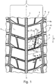
- FIG. 11 shows a plan view of a circumferential section of a tread of a pneumatic vehicle tire with two running in a central tread region Z.
- FIG middle tread block rows 1 and two in Fig. 1 merely indicated shoulder-side rows of tread blocks 2.
- the middle rows of tread blocks 1 and thus also the tread are designed to be directional, the pneumatic vehicle tire being mounted on the vehicle in such a way that it meets the in Fig. 1 has the rolling direction symbolized by the arrow R when driving forward.
- the middle rows of tread blocks 1 are separated from one another by a central circumferential groove 3 which runs straight along the tire equatorial plane (line A-A) and in the exemplary embodiment shown in plan view.
- the middle tread block rows 1 are separated by shoulder-side circumferential grooves 4, which in the embodiment shown run in a zigzag shape in plan view and are composed of alternating shorter sections 4a and longer sections 4b.
- the circumferential grooves 3, 4 are designed to the tread depth provided for the respective pneumatic vehicle tire, which for passenger cars, vans or light trucks is usually 6.5 mm to 9.0 mm.
- Each middle row of tread blocks 1 has a plurality of circumferentially successive tread blocks 5, which are separated from one another by transverse grooves 6 that run straight in plan view and transverse grooves 7 that are slightly bent at one point in plan view, with one straight transverse groove 6 alternating with one bent within each row of tread blocks 1
- Transverse groove 7 follows.
- the straight transverse grooves 6 open into the longer sections 4b of the respective circumferential groove 4 and the kinked transverse grooves 7 open into the shorter sections 4a of the respective circumferential groove 4.
- the transverse grooves 6, 7 are oriented in such a way that when the tire rolls forwards with their tread-inner groove ends lying on the central circumferential groove 3, they first enter the ground, so that the transverse grooves 6, 7 from the one middle row of tread blocks 1 are in opposite directions with respect to the circumferential direction to the transverse grooves 6, 7 from the other middle Profile block row 1 are inclined.
- the tread therefore has, at least in the central tread area Z, an "arrowed" profile with transverse grooves 6, 7 running flat "V-shaped" over the width of the central tread area Z.
- the profile blocks 5 located within the one middle row of profile blocks 1 have positions that correspond to the profile blocks 5 located within the other middle row of profile blocks 1 with respect to the circumferential direction.
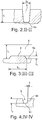
- the straight transverse grooves 6 run to the axial direction at an angle ⁇ of 10 ° to 35 °, in particular up to 25 °, have a width B 1 ( Fig. 2 ) from 3.0 mm to 7.0 mm and in the radial direction a depth T 1 ( Fig. 2 ) from 60% to 100% of the tread depth, whereby the depth T 1 ( Fig. 2 ) is preferably at least 1.5 mm less than the profile depth.
- Each bent transverse groove 7 is composed in plan view of a tread-inside groove section 7a opening into the central circumferential groove 3 and a tread-outside groove section 7b adjoining the short section 4a of the corresponding shoulder-side circumferential groove 4.
- the groove sections 7a on the inside of the tread run straight in plan view and, within a row of tread blocks 1, parallel to the straight transverse grooves 6 and therefore also at the aforementioned angle ⁇ and have a width B 2 of 3.0 mm to 7.0 mm at the tread periphery,
- the width B 2 in the embodiment shown is smaller than the width B 1 of the straight transverse grooves 6.
- Each tread-outside groove section 7b extends - based on the center line m QR of its transverse groove 7 - to the axial direction at an angle greater than the angle ⁇ ⁇ from 30 ° to 45 ° and spreads on one side and starting from the groove section 7a on the inside of the tread in the direction of the corresponding shoulder-side circumferential groove 4, so that, as already mentioned, it directly adjoins one of the shorter sections 4a of the circumferential groove 4.
- the transverse groove 7 has a preferably constant depth of 60% to 100% of the profile depth over its entire extent in the radial direction.
- each straight transverse groove 6 is at the groove bottom 6a (see also Fig. 2 ) a base elevation 8 is formed, which locally reduces the depth of the transverse groove 6, connects the respective adjacent middle profile blocks 5 to one another and has a distance a 1 of 10.0 mm to 25.0 mm in the axial direction from the central circumferential groove 3.
- a base elevation 8 is formed, which locally reduces the depth of the transverse groove 6, connects the respective adjacent middle profile blocks 5 to one another and has a distance a 1 of 10.0 mm to 25.0 mm in the axial direction from the central circumferential groove 3.
- the base elevation 8 in the illustrated embodiment is flat trapezoidal, has a width b 1 of 7.0 mm to at its base located on the groove base 6a 15.0 mm and compared to the level of the groove bottom 6a in the radial direction a height h 1 of 1.0 mm to 3.0 mm.
- every second tread block 5 is provided with an inclined groove 9 which traverses it and opens into a straight transverse groove 6 and a kinked transverse groove 7, the inclined grooves 9 formed within a tread block row 1 running parallel to one another in plan view.
- Each inclined groove 9 runs straight in plan view, relative to the circumferential direction at an angle ⁇ of 6 ° to 12 ° and with respect to the tire circumferential direction in the same direction as the transverse grooves 6, 7, based on its center line m SN aligned in the running direction of the groove.
- the inclined grooves 9 each have an infeed groove end 9a that first enters the ground when the tire rolls forwards and an outflowing groove end 9b, with the infeed groove end 9a on the inside of the tread groove section 7a of the respective kinked transverse groove 7 and the outflowing groove end 9b in the area which is located radially outside the corresponding base elevation 8 of the respective straight transverse groove 6.
- Each inclined groove 9 has a depth T 2 in the radial direction ( Fig. 4 ) from 3.0 mm to 5.0 mm and becomes continuously wider from its incoming groove end 9a to its outgoing groove end 9b, with a width B a of 2.0 mm at the incoming groove end 9a - determined on the respective transverse groove 7 up to 6.0 mm, in particular up to 4.0 mm, and at the tapering groove end 9b - determined on the respective transverse groove 6 - a width B b of 140% to 300%, in particular from 160% to 200%, of the width B. a has.
- each inclined groove 9 has a groove base 9c and groove flanks 9d which, viewed in cross section, extend to the radial direction at an angle ⁇ of 0 ° to 7 °, in particular of up to 5 °.
- the profile blocks can be provided with a plurality of incisions in a manner known per se.
- straight transverse grooves can be provided in plan view.
- the circumferential grooves can each run straight or at least in sections in a zigzag or undulating manner.
Landscapes
- Engineering & Computer Science (AREA)
- Mechanical Engineering (AREA)
- Tires In General (AREA)
Description
- Die Erfindung betrifft einen Fahrzeugluftreifen mit einem Laufstreifen mit zwei durch eine Umfangsrille voneinander getrennten mittleren Profilblockreihen mit Profilblöcken und mit diese voneinander trennenden, zur axialen Richtung gewinkelten, innerhalb jeder Profilbockreihe gegenüber der Reifenumfangsrichtung gleichsinnig orientierten Querrillen, wobei Querrillen vorgesehen sind, in welchen jeweils eine Grundanhebung ausgebildet ist, und wobei Profilblöcke vorgesehen sind, in welchen jeweils eine in den jeweiligen Profilblock durchquerende Schrägnut verläuft, welche in die eine Querrille im Bereich der und radial außerhalb der Grundanhebung einmündet, zur Umfangsrichtung unter einem Winkel von 6° bis 12° verläuft und eine über ihren Verlauf kontinuierlich zunehmende Breite und daher ein schmales und ein breites Nutende aufweist.
- Ein derartiger Fahrzeugluftreifen, welcher für das Fahren unter winterlichen Fahrbedingungen besonders gut geeignet ist, ist beispielsweise aus der
DE 10 2016 218 980 A1 und aus derDE 10 2016 218 981 A1 bekannt. Die Querrillen setzen sich jeweils aus zwei unter einem stumpfen Winkel aneinander anschließenden Rillenabschnitten zusammen, wobei in jeder Querrille eine über ihre Knickstelle verlaufende und daher in Draufsicht gewinkelte Grundanhebung ausgebildet ist. Ferner sind in sämtlichen Profilblöcken der beiden mittleren Profilblockreihen in die Querrillen einmündende Schrägnuten ausgebildet, welche zur Umfangsrichtung unter einem Winkel von 3° bis 15°, insbesondere von 5° bis 15°, verlaufen, wobei sämtliche Schrägnuten bezüglich der Umfangsrichtung gleichsinnig geneigt sind. Die Schrägnuten weisen eine Tiefe von 1,5 mm bis 2,5 mm, an ihrem breiten Nutende eine Breite von 1,5 mm bis 2,5 mm und an ihrem schmalen Nutende eine Breite von 0,5 mm bis 1,5 mm auf. Durch die Grundanhebungen werden die Profilblöcke der mittleren Profilblockreihen gegeneinander abgestützt, wodurch die Steifigkeit der Profilblockreihen erhöht wird. Die Schrägnuten unterstützen die Wasserableitung und in den "geknickten" Querrillen kann sich gut Schnee ansammeln, wodurch der Schneegriff verbessert wird. Die sich verringernde Breite der Schrägnuten ist insbesondere im Hinblick auf die Steifigkeit der Profilblöcke vorteilhaft. - Der Erfindung liegt die Aufgabe zugrunde, einen Fahrzeugluftreifen der eingangs genannten Art hinsichtlich seiner Wasserableiteigenschaften weiter zu verbessern. Insbesondere sollen weitere Verbesserungen im Hinblick auf das Aquaplaning-und das Bremsverhalten auf nasser Fahrbahn erzielt werden.
- Gelöst wird die gestellte Aufgabe erfindungsgemäß dadurch,
- dass der Laufstreifen laufrichtungsgebunden ausgeführt ist,
- wobei in jeder Profilblockreihe ausschließlich jeder zweite Profilblock mit einer Schrägnut und ausschließlich jede zweite Querrille mit einer Grundanhebung versehen ist,
- wobei in jeder der beiden mittleren Profilblockreihen die Schrägnuten bezüglich der Reifenumfangsrichtung gleichsinnig zu den Querrillen geneigt sind,
- wobei die Querrillen und die Schrägnuten in der einen mittleren Profilblockreihe zu den Querrillen und Schrägnuten in der anderen mittleren Profilblockreihe derart bezüglich der Reifenumfangsrichtung gegensinnig geneigt sind, dass bei am Fahrzeug montiertem Fahrzeugluftreifen bei Vorwärtsfahrt die Querrillen mit ihren weiter laufstreifeninnenseitig befindlichen Rillenenden, und die Schrägnuten mit ihren schmalen Nutenden zuerst in den Untergrund eintreten.
- Wie nachfolgend erläutert, ermöglicht die laufrichtungsgebundene Ausführung des Laufstreifenprofiles eine für die Wasserableiteigenschaften besonders vorteilhafte Orientierung der Querrillen und der Schrägnuten. Sämtliche Schrägnuten sind in den mittleren Profilblockreihen gleichsinnig zu den Querrillen geneigt, wodurch beim Fahren auf nasser Fahrbahn von den Schrägnuten aufgenommenes Wasser zunächst in die Querrille, von dieser unmittelbar in die jeweilige als Hauptentwässerungsrille wirkende schulterseitige Umfangsrille und daher in Richtung Laufstreifenaußenseite abgeleitet wird. Da bei sämtlichen Schrägnuten das breite Nutende, über welche das Wasser aus der jeweiligen Schrägnut herausfließt, bei einer Grundanhebung liegt, wird das aus den Schrägnuten fließende Wasser auf verwirbelungsarme Weise unmittelbar über die Grundanhebungen hinweggeleitet. Da die Breite der Schrägnuten in Wasserflussrichtung kontinuierlich zunimmt, ist zudem die Gefahr, dass eine Schrägnut "überläuft", äußerst gering. Es sind dadurch die Wasserableiteigenschaften des Laufstreifenprofils gegenüber Laufstreifenprofilen der eingangs genannten Art auch derart verbessert, dass beim Bremsen auf nasser Fahrbahn die Gefahr eines Aquaplaning begünstigenden "Wasserstaus" in den Rillen und Nuten verringert ist.
- Gemäß einer bevorzugten Ausführungsvariante beträgt die Breite der Schrägnuten am breiten Nutende 140% bis 300%, insbesondere 160% bis 200%, der Breite der Schrägnuten am schmalen Nutende. Eine solche Breitenvariation bewirkt insbesondere eine weitere Verbesserung der Wasserableiteigenschaften des Laufstreifenprofils.
- Es ist dabei ferner von Vorteil, wenn die Breite der Schrägnuten am schmalen Nutende 2,0 mm bis 6,0 mm, insbesondere bis zu 4,0 mm, beträgt.
- Gemäß einer weiteren bevorzugten Ausführungsvariante weisen die Schrägnuten in radialer Richtung eine Tiefe von 3,0 mm bis 5,0 mm auf. Durch diese Maßnahme ist das Laufstreifenprofil im Hinblick auf die Wasserableiteigenschaften und die Steifigkeit seiner mittleren Profilblockreihen sehr ausgewogen.
- Die erwähnten Grundanhebungen verringern das Leervolumen in den entsprechenden Querrillen. Für gute Wasserableiteigenschaften ist es daher vorteilhaft, wenn die Querrillen, in welchen jeweils eine Grundanhebung ausgebildet ist, in Draufsicht gerade verlaufen.
- Gemäß einer weiteren bevorzugten Ausführungsvariante setzen sich die Querrillen, in welchen keine Grundanhebungen ausgebildet sind, in Draufsicht jeweils aus einem laufstreifeninnenseitigen Rillenabschnitt und einem gegenüber dem laufstreifeninnenseitigen Rillenabschnitt zur axialen Richtung stärker geneigten laufstreifenaußenseitigen Rillenabschnitt zusammen, wobei die Schrägnuten jeweils in einen laufstreifeninnenseitigen Rillenabschnitt einmünden.
- Bei dieser Variante ist es ferner vorteilhaft, wenn die laufstreifeninnenseitigen Rillenabschnitte der Querrillen, in welchen keine Grundanhebungen ausgebildet sind, schmäler sind als jene Querrillen, in welchen jeweils eine Grundanhebung ausgebildet ist. Durch diese Maßnahme lässt sich insbesondere die Steifigkeit der Profilblockreihe vorteilhaft beeinflussen.
- Gemäß einer weiteren bevorzugten Ausführungsvariante befinden sich die zu der einen mittleren Profiblockreihe gehörenden Profilblöcke zu den zu der anderen mittleren Profilblockreihe gehörenden Profilblöcken bezüglich der Umfangsrichtung in übereinstimmenden Positionen, wobei die Schrägnuten in axial nebeneinander liegenden Profilblöcken verlaufen.
- Gemäß einer weiteren bevorzugten Ausführungsvariante weisen die Grundanhebungen in den Querrillen zu der die Profilblockreihen trennenden Umfangsrille in axialer Richtung einen Abstand von 10,0 mm bis 25,0 mm auf. In solchen Abständen positionierte Grundanhebungen wirken sich auf die Stabilisierung der entsprechenden Profilblöcke besonders vorteilhaft aus.
- Ferner ist es bevorzugt, wenn die Schrägnuten Nutflanken aufweisen, welche, im Querschnitt betrachtet, zur radialen Richtung unter einem Winkel von 0° bis zu 7°, insbesondere von bis zu 5°, verlaufen. Derartige Schrägnuten wirken stabilisierend, wodurch insbesondere die Nassbremseigenschaften des Reifens weiter verbessert werden.
- Gemäß einer weiteren bevorzugten Ausführungsvariante sind die Querrillen, in welchen keine Grundanhebungen ausgebildet sind, in radialer Richtung insbesondere um 1,5 mm seichter ausgeführt als die Querrillen, in welchen jeweils eine Grundanhebung ausgebildet ist. Durch solche Querrillen lässt sich die Steifigkeit der Profilblockreihe erhöhen. Die Querrillen befinden sich dabei an den einlaufenden Enden der Schrägnuten, sodass aus den Schrägnuten kaum Wasser in diese Querrillen geleitet wird.
- Mit den erwähnten Maßnahmen lässt sich eine im Hinblick auf die Wasserableiteigenschaften besonders vorteilhafte Laufstreifenprofilierung erreichen, wenn die die Profilblockreihen voneinander trennende Umfangsrille entlang der Reifenäquatorialebene verläuft.
- Weitere Merkmale, Vorteile und Einzelheiten der Erfindung werden nun anhand der Zeichnung, die schematisch ein Ausführungsbeispiel der Erfindung zeigt, näher beschrieben. Dabei zeigen
-
Fig. 1 eine schematische Draufsicht auf einen Ausschnitt eines Laufstreifens eines Fahrzeugluftreifens mit einer Ausführungsvariante der Erfindung, -
Fig. 2 einen Schnitt entlang der Linie II-II derFig. 1 , -
Fig. 3 einen Schnitt entlang der Linie III-III derFig. 1 und -
Fig. 4 einen Schnitt entlang der Linie IV-IV derFig. 1 . - Gemäß der Erfindung ausgeführte Fahrzeugluftreifen sind Reifen eines beliebigen Typs, insbesondere Reifen in Radialbauart für Personenkraftwagen, Vans, Light-Trucks oder Nutzfahrzeugreifen.
-
Fig. 1 zeigt eine Draufsicht auf einen Umfangsabschnitt eines Laufstreifens eines Fahrzeugluftreifens mit zwei in einem zentralen Laufstreifenbereich Z verlaufenden mittleren Profilblockreihen 1 und zwei inFig. 1 lediglich angedeuteten schulterseitigen Profilblockreihen 2. Die mittleren Profilblockreihen 1 und damit auch der Laufstreifen sind laufrichtungsgebunden ausgeführt, wobei der Fahrzeugluftreifen derart am Fahrzeug zu montieren ist, dass er die inFig. 1 durch den Pfeil R symbolisierte Abrollrichtung bei Vorwärtsfahrt aufweist. - Die mittleren Profilblockreihen 1 sind von einer entlang der Reifenäquatorialebene (Linie A-A) sowie beim gezeigten Ausführungsbeispiel in Draufsicht gerade verlaufenden, zentralen Umfangsrille 3 voneinander getrennt. Zu den schulterseitigen Profilblockreihen 2 sind die mittleren Profilblockreihen 1 durch schulterseitige Umfangsrillen 4 getrennt, welche beim gezeigten Ausführungsbeispiel in Draufsicht zick-zack-förmig verlaufen und sich aus abwechselnd aufeinanderfolgenden kürzeren Abschnitten 4a und längeren Abschnitten 4b zusammensetzen. Die Umfangsrillen 3,4 sind auf die für den jeweiligen Fahrzeugluftreifen vorgesehene Profiltiefe ausgeführt, welche für Personenkraftwagen, Vans oder Light-Trucks üblicherweise 6,5 mm bis 9,0 mm beträgt.
- Jede mittlere Profilblockreihe 1 weist eine Vielzahl von in Umfangsrichtung aufeinanderfolgenden Profilblöcken 5 auf, welche durch in Draufsicht gerade verlaufende Querrillen 6 und in Draufsicht an einer Stelle geringfügig geknickte Querrillen 7 voneinander getrennt sind, wobei innerhalb jeder Profilblockreihe 1 abwechselnd eine gerade Querrille 6 auf eine geknickte Querrille 7 folgt. Die geraden Querrillen 6 münden in die längeren Abschnitte 4b der jeweiligen Umfangsrille 4 und die geknickten Querrillen 7 münden in die kürzeren Abschnitte 4a der jeweiligen Umfangsrille 4.
- Die Querrillen 6, 7 sind derart orientiert, dass sie beim Abrollen des Reifens bei Vorwärtsfahrt mit ihren an der zentralen Umfangsrille 3 liegenden, laufstreifeninnseitigen Rillenenden zuerst in den Untergrund eintreten, sodass die Querrillen 6, 7 aus der einen mittleren Profilblockreihe 1 bezüglich der Umfangsrichtung gegensinnig zu den Querrillen 6, 7 aus der anderen mittleren Profilblockreihe 1 geneigt sind. Der Laufstreifen weist daher zumindest im zentralen Laufstreifenbereich Z ein "gepfeiltes" Profil mit flach "V-förmig" über die Breite des zentralen Laufstreifenbereiches Z verlaufenden Querrillen 6, 7 auf. Bei der gezeigten Ausführungsvariante weisen die innerhalb der einen mittleren Profilblockreihe 1 befindlichen Profilblöcke 5 zu den innerhalb der anderen mittleren Profilblockreihe 1 befindlichen Profilblöcken 5 bezüglich der Umfangsrichtung übereinstimmende Positionen auf.
- Die gerade verlaufenden Querrillen 6 verlaufen zur axialen Richtung unter einem Winkel α von 10° bis 35°, insbesondere von bis zu 25°, weisen an der Laufstreifenperipherie eine Breite B1 (
Fig. 2 ) von 3,0 mm bis 7,0 mm und in radialer Richtung eine Tiefe T1 (Fig. 2 ) von 60% bis 100% der Profiltiefe auf, wobei die Tiefe T1 (Fig. 2 ) vorzugsweise um mindestens 1,5 mm geringer ist als die Profiltiefe. - Gemäß
Fig. 1 setzt sich jede geknickte Querrille 7 in Draufsicht aus einem in die zentrale Umfangsrille 3 einmündenden, laufstreifeninnenseitigen Rillenabschnitt 7a und einem an den kurzen Abschnitt 4a der entsprechenden schulterseitigen Umfangsrille 4 anschließenden, laufstreifenaußenseitigen Rillenabschnitt 7b zusammen. Die laufstreifeninnenseitigen Rillenabschnitte 7a verlaufen in Draufsicht gerade sowie innerhalb einer Profilblockreihe 1 parallel zu den gerade verlaufenden Querrillen 6 und daher ebenfalls unter dem bereits erwähnten Winkel α und weisen an der Laufstreifenperipherie eine Breite B2 von 3,0 mm bis 7,0 mm auf, wobei die Breite B2 beim gezeigten Ausführungsbeispiel kleiner ist als die Breite B1 der gerade verlaufenden Querrillen 6. Jeder laufstreifenaußenseitige Rillenabschnitt 7b erstreckt sich - bezogen auf die Mittellinie mQR seiner Querrille 7 - zur axialen Richtung unter einem größer als der Winkel α ausgeführten Winkel β von 30° bis 45° und verbreitet sich einseitig sowie ausgehend vom laufstreifeninnenseitigen Rillenabschnitt 7a in Richtung zur entsprechenden schulterseitigen Umfangsrille 4, sodass er, wie bereits erwähnt, an einen der kürzeren Abschnitte 4a der Umfangsrille 4 unmittelbar anschließt. Die Querrille 7 weist über ihre gesamte Erstreckung in radialer Richtung eine vorzugsweise konstante Tiefe von 60% bis 100% der Profiltiefe auf. - In jeder gerade verlaufenden Querrille 6 ist am Rillengrund 6a (siehe auch
Fig. 2 ) eine Grundanhebung 8 ausgebildet, welche die Tiefe der Querrille 6 lokal verringert, die jeweiligen einander benachbarten mittleren Profilblöcke 5 aneinander anbindet und zur zentralen Umfangsrille 3 in axialer Richtung einen Abstand a1 von 10,0 mm bis 25,0 mm aufweist. GemäßFig. 3 , welche einen in Verlaufsrichtung einer Querrille 6 ausgerichteten Längsschnitt durch die Grundanhebung 8 zeigt, ist die Grundanhebung 8 beim gezeigten Ausführungsbeispiel, im Längsschnitt betrachtet, flach trapezartig ausgeführt, weist an ihrer am Rillengrund 6a liegenden Basis eine Breite b1 von 7,0 mm bis 15,0 mm und gegenüber dem Niveau des Rillengrundes 6a in radialer Richtung eine Höhe h1 von 1,0 mm bis 3,0 mm auf. - Wie
Fig. 1 zeigt, ist innerhalb jeder mittleren Profilblockreihe 1 jeder zweite Profilblock 5 mit einer ihn durchquerenden, in eine gerade verlaufende Querrille 6 und eine geknickte Querrille 7 einmündenden Schrägnut 9 versehen, wobei die innerhalb einer Profilblockreihe 1 ausgebildeten Schrägnuten 9 in Draufsicht parallel zueinander verlaufen. Jede Schrägnut 9 verläuft - bezogen auf ihre in Rillenlaufrichtung ausgerichtete Mittellinie mSN - in Draufsicht gerade, relativ zur Umfangsrichtung unter einem Winkel γ von 6° bis 12° und bezüglich der Reifenumfangsrichtung gleichsinnig zu den Querrillen 6, 7 geneigt. - Die Schrägnuten 9 weisen jeweils ein beim Abrollen des Reifens bei Vorwärtsfahrt zuerst in den Untergrund eintretendes, einlaufendes Nutende 9a und ein auslaufendes Nutende 9b auf, wobei sich das einlaufende Nutende 9a am laufstreifeninnenseitigen Rillenabschnitt 7a der jeweiligen geknickten Querrille 7 und das auslaufende Nutende 9b im Bereich der und radial außerhalb der entsprechenden Grundanhebung 8 der jeweiligen gerade verlaufenden Querrille 6 befindet.
- Jede Schrägnut 9 weist in radialer Richtung eine Tiefe T2 (
Fig. 4 ) von 3,0 mm bis 5,0 mm auf und wird von ihrem einlaufenden Nutende 9a zu ihrem auslaufenden Nutende 9b kontinuierlicher breiter, wobei sie am einlaufenden Nutende 9a - ermittelt an der jeweiligen Querrille 7 - eine Breite Ba von 2,0 mm bis 6,0 mm, insbesondere von bis zu 4,0 mm, und am auslaufenden Nutende 9b - ermittelt an der jeweiligen Querrille 6 - eine Breite Bb von 140% bis 300%, insbesondere von 160% bis 200%, der Breite Ba aufweist. GemäßFig. 4 weist jede Schrägnut 9 einen Nutgrund 9c und Nutflanken 9d auf, welche, im Querschnitt betrachtet, zur radialen Richtung unter einem Winkel δ von 0° bis zu 7°, insbesondere von bis zu 5°, verlaufen. - Die Erfindung ist auf die beschriebene und dargestellte Ausführungsvariante nicht eingeschränkt.
- Insbesondere können die Profilblöcke in an sich bekannter Weise mit einer Vielzahl von Einschnitten versehen sein. Anstelle der geknickten Querrillen können in Draufsicht gerade verlaufende Querrillen vorgesehen sein. Ferner können die Umfangsrillen in Draufsicht jeweils gerade oder zumindest abschnittweise zick-zack oder wellenförmig verlaufen.
-
- 1
- mittlere Profilblockreihe
- 2
- schulterseitige Profilblockreihe
- 3
- zentrale Umfangsrille
- 4
- schulterseitige Umfangsrille
- 4a
- kürzerer Abschnitt
- 4b
- längerer Abschnitt
- 5
- Profilblock
- 6
- Querrille
- 6a
- Rillengrund
- 7
- Querrille
- 7a
- Iaufstreifeninnenseitiger Rillenabschnitt
- 7b
- laufstreifenaußenseitiger Rillenabschnitt
- 8
- Grundanhebung
- 9
- Schrägnut
- 9a
- einlaufendes Nutende
- 9b
- auslaufendes Nutende
- 9c
- Nutgrund
- 9d
- Nutflanken
- a1
- Abstand
- A-A
- Linie (Reifenäquatorialebene)
- b1
- Breite
- B1, B2
- Breite
- Ba, Bb
- Breite
- h1
- Höhe
- mQR
- Mittellinie
- mSN
- Mittellinie
- R
- Pfeil (Abrollrichtung)
- T1, T2
- Tiefe
- Z
- zentraler Laufstreifenbereich
- α, β, γ, δ
- Winkel
Claims (12)
- Fahrzeugluftreifen mit einem Laufstreifen mit zwei durch eine Umfangsrille (3) voneinander getrennten mittleren Profilblockreihen (1) mit Profilblöcken (5) und mit diese voneinander trennenden, zur axialen Richtung gewinkelten (α, β), innerhalb jeder Profilbockreihe (1) gegenüber der Reifenumfangsrichtung gleichsinnig orientierten Querrillen (6, 7),wobei Querrillen (6) vorgesehen sind, in welchen jeweils eine Grundanhebung (8) ausgebildet ist, undwobei Profilblöcke (5) vorgesehen sind, in welchen jeweils eine den jeweiligen Profilblock (5) durchquerende Schrägnut (9) verläuft, welche in die eine Querrille (6) im Bereich der und radial außerhalb der Grundanhebung (8) einmündet, zur Umfangsrichtung unter einem Winkel (γ) von 6° bis 12° verläuft und eine über ihren Verlauf kontinuierlich zunehmende Breite (Ba, Bb) und daher ein schmales und ein breites Nutende (9a, 9b) aufweist,dadurch gekennzeichnet,dass der Laufstreifen laufrichtungsgebunden ausgeführt ist,wobei in jeder Profilblockreihe (1) ausschließlich jeder zweite Profilblock (5) mit einer Schrägnut (9) und ausschließlich jede zweite Querrille (6) mit einer Grundanhebung (8) versehen ist,wobei in jeder der beiden mittleren Profilblockreihen (1) die Schrägnuten (9) bezüglich der Reifenumfangsrichtung gleichsinnig zu den Querrillen (6, 7) geneigt sind,wobei die Querrillen (6, 7) und die Schrägnuten (9) in der einen mittleren Profilblockreihe (1) zu den Querrillen (6, 7) und Schrägnuten (9) in der anderen mittleren Profilblockreihe (1) derart bezüglich der Reifenumfangsrichtung gegensinnig geneigt sind, dass bei am Fahrzeug montiertem Fahrzeugluftreifen bei Vorwärtsfahrt (R) die Querrillen (6, 7) mit ihren weiter laufstreifeninnenseitig befindlichen Rillenenden, und die Schrägnuten (9) mit ihren schmalen Nutenden (9a) zuerst in den Untergrund eintreten.
- Fahrzeugluftreifen nach Anspruch 1, dadurch gekennzeichnet, dass die Breite (Bb) der Schrägnuten (9) am breiten Nutende (9b) 140% bis 300%, insbesondere 160% bis 200%, der Breite (Ba) der Schrägnuten (9) am schmalen Nutende (9a) beträgt.
- Fahrzeugluftreifen nach Anspruch 1 oder 2, dadurch gekennzeichnet, dass die Breite (Ba) der Schrägnuten (9) am schmalen Nutende (9a) 2,0 mm bis 6,0 mm, insbesondere bis zu 4,0 mm, beträgt.
- Fahrzeugluftreifen nach einem der Ansprüche 1 bis 3, dadurch gekennzeichnet, dass die Schrägnuten (9) in radialer Richtung eine Tiefe (T3) von 3,0 mm bis 5,0 mm aufweisen.
- Fahrzeugluftreifen nach einem der Ansprüche 1 bis 4, dadurch gekennzeichnet, dass die Querrillen (6), in welchen jeweils eine Grundanhebung (8) ausgebildet ist, in Draufsicht gerade verlaufen.
- Fahrzeugluftreifen nach einem der Ansprüche 1 bis 5, dadurch gekennzeichnet, dass sich die Querrillen (7), in welchen keine Grundanhebungen (8) ausgebildet sind, in Draufsicht jeweils aus einem laufstreifeninnenseitigen Rillenabschnitt (7a) und einem gegenüber dem laufstreifeninnenseitigen Rillenabschnitt (7a) zur axialen Richtung stärker geneigten laufstreifenaußenseitigen Rillenabschnitt (7b) zusammensetzen, wobei die Schrägnuten (9) jeweils in einen laufstreifeninnenseitigen Rillenabschnitt (7a) einmünden.
- Fahrzeugluftreifen nach Anspruch 6, dadurch gekennzeichnet, dass die laufstreifeninnenseitigen Rillenabschnitte (7a) der Querrillen (7), in welchen keine Grundanhebungen (8) ausgebildet sind, schmäler sind als jene Querrillen (6), in welchen jeweils eine Grundanhebung (8) ausgebildet ist.
- Fahrzeugluftreifen nach einem der Ansprüche 1 bis 7, dadurch gekennzeichnet, dass sich die zu der einen mittleren Profiblockreihe (1) gehörenden Profilblöcke (5) zu den zu der anderen mittleren Profilblockreihe (1) gehörenden Profilblöcken (5) bezüglich der Umfangsrichtung in übereinstimmenden Positionen befinden, wobei die Schrägnuten (9) in axial nebeneinander liegenden Profilblöcken (5) verlaufen.
- Fahrzeugluftreifen nach einem der Ansprüche 1 bis 8, dadurch gekennzeichnet, dass die Grundanhebungen (8) in den Querrillen (6) zu der die Profilblockreihen (1) trennenden Umfangsrille (3) in axialer Richtung einen Abstand (a1) von 10,0 mm bis 25,0 mm aufweisen.
- Fahrzeugluftreifen nach einem der Ansprüche 1 bis 9, dadurch gekennzeichnet, dass die Schrägnuten (9) Nutflanken (9d) aufweisen, welche im Querschnitt betrachtet, zur radialen Richtung unter einem Winkel (δ) von 0° bis zu 7°, insbesondere von bis zu 5°, verlaufen.
- Fahrzeugluftreifen nach einem der Ansprüche 1 bis 10, dadurch gekennzeichnet, dass die Querrillen (7), in welchen keine Grundanhebungen (8) ausgebildet sind, in radialer Richtung insbesondere um 1,5 mm seichter ausgeführt sind als die Querrillen (6), in welchen jeweils eine Grundanhebung (8) ausgebildet ist.
- Fahrzeugluftreifen nach einem der Ansprüche 1 bis 11, dadurch gekennzeichnet, dass die die Profilblockreihen (1) voneinander trennende Umfangsrille (3) entlang der Reifenäquatorialebene (A-A) verläuft.
Applications Claiming Priority (1)
| Application Number | Priority Date | Filing Date | Title |
|---|---|---|---|
| DE102019201010.5A DE102019201010A1 (de) | 2019-01-28 | 2019-01-28 | Fahrzeugluftreifen |
Publications (2)
| Publication Number | Publication Date |
|---|---|
| EP3686033A1 EP3686033A1 (de) | 2020-07-29 |
| EP3686033B1 true EP3686033B1 (de) | 2021-10-27 |
Family
ID=68470304
Family Applications (1)
| Application Number | Title | Priority Date | Filing Date |
|---|---|---|---|
| EP19207331.0A Active EP3686033B1 (de) | 2019-01-28 | 2019-11-06 | Fahrzeugluftreifen |
Country Status (2)
| Country | Link |
|---|---|
| EP (1) | EP3686033B1 (de) |
| DE (1) | DE102019201010A1 (de) |
Families Citing this family (1)
| Publication number | Priority date | Publication date | Assignee | Title |
|---|---|---|---|---|
| DE102021201350A1 (de) * | 2021-02-12 | 2022-08-18 | Continental Reifen Deutschland Gmbh | Fahrzeugluftreifen |
Family Cites Families (6)
| Publication number | Priority date | Publication date | Assignee | Title |
|---|---|---|---|---|
| JP3203057B2 (ja) * | 1992-07-28 | 2001-08-27 | 住友ゴム工業株式会社 | 空気入りタイヤ |
| JPH0648117A (ja) * | 1992-07-28 | 1994-02-22 | Toyo Tire & Rubber Co Ltd | ラジアルタイヤ |
| JP4580387B2 (ja) * | 2004-05-27 | 2010-11-10 | 株式会社ブリヂストン | 空気入りタイヤ |
| DE102007061148A1 (de) * | 2007-12-17 | 2009-06-18 | Continental Aktiengesellschaft | Fahrzeugluftreifen |
| DE102016218980A1 (de) | 2016-09-30 | 2018-04-05 | Continental Reifen Deutschland Gmbh | Fahrzeugluftreifen |
| DE102016218981A1 (de) | 2016-09-30 | 2018-04-05 | Continental Reifen Deutschland Gmbh | Fahrzeugluftreifen |
-
2019
- 2019-01-28 DE DE102019201010.5A patent/DE102019201010A1/de not_active Withdrawn
- 2019-11-06 EP EP19207331.0A patent/EP3686033B1/de active Active
Also Published As
| Publication number | Publication date |
|---|---|
| DE102019201010A1 (de) | 2020-07-30 |
| EP3686033A1 (de) | 2020-07-29 |
Similar Documents
| Publication | Publication Date | Title |
|---|---|---|
| DE19753819B4 (de) | Laufflächenprofil eines Winterreifens | |
| EP3589500B1 (de) | Fahrzeugluftreifen | |
| EP3589501A1 (de) | Fahrzeugluftreifen | |
| EP3256334B1 (de) | Fahrzeugluftreifen | |
| EP3300926B1 (de) | Fahrzeugluftreifen | |
| DE102019213044A1 (de) | Fahrzeugluftreifen | |
| WO2021013439A1 (de) | Fahrzeugluftreifen | |
| EP3256335B1 (de) | Fahrzeugluftreifen | |
| EP3686033B1 (de) | Fahrzeugluftreifen | |
| EP3450217B1 (de) | Fahrzeugluftreifen | |
| EP3765311B1 (de) | Fahrzeugluftreifen | |
| EP3300925B1 (de) | Fahrzeugluftreifen | |
| DE19957914A1 (de) | Fahrzeugluftreifen | |
| EP1798067B1 (de) | Laufflächenprofil | |
| EP3418076B1 (de) | Fahrzeugluftreifen | |
| WO2011057852A1 (de) | Laufstreifenprofil eines fahrzeugreifens | |
| EP4281296B1 (de) | Fahrzeugluftreifen | |
| EP3888951A1 (de) | Fahrzeugluftreifen | |
| EP3785937B1 (de) | Fahrzeugluftreifen | |
| EP1695845B1 (de) | Fahrzeugreifen mit einem Laufstreifenprofil | |
| EP3551474B1 (de) | Fahrzeugluftreifen | |
| EP4667240A1 (de) | Fahrzeugreifen | |
| EP4706991A1 (de) | Zu einer produktlinie gehörende erste und zweite fahrzeugreifen | |
| WO2016155854A1 (de) | Fahrzeugluftreifen | |
| DE102019200441A1 (de) | Fahrzeugluftreifen |
Legal Events
| Date | Code | Title | Description |
|---|---|---|---|
| PUAI | Public reference made under article 153(3) epc to a published international application that has entered the european phase |
Free format text: ORIGINAL CODE: 0009012 |
|
| STAA | Information on the status of an ep patent application or granted ep patent |
Free format text: STATUS: THE APPLICATION HAS BEEN PUBLISHED |
|
| AK | Designated contracting states |
Kind code of ref document: A1 Designated state(s): AL AT BE BG CH CY CZ DE DK EE ES FI FR GB GR HR HU IE IS IT LI LT LU LV MC MK MT NL NO PL PT RO RS SE SI SK SM TR |
|
| AX | Request for extension of the european patent |
Extension state: BA ME |
|
| RAP1 | Party data changed (applicant data changed or rights of an application transferred) |
Owner name: CONTINENTAL REIFEN DEUTSCHLAND GMBH |
|
| STAA | Information on the status of an ep patent application or granted ep patent |
Free format text: STATUS: REQUEST FOR EXAMINATION WAS MADE |
|
| 17P | Request for examination filed |
Effective date: 20210129 |
|
| RBV | Designated contracting states (corrected) |
Designated state(s): AL AT BE BG CH CY CZ DE DK EE ES FI FR GB GR HR HU IE IS IT LI LT LU LV MC MK MT NL NO PL PT RO RS SE SI SK SM TR |
|
| GRAP | Despatch of communication of intention to grant a patent |
Free format text: ORIGINAL CODE: EPIDOSNIGR1 |
|
| STAA | Information on the status of an ep patent application or granted ep patent |
Free format text: STATUS: GRANT OF PATENT IS INTENDED |
|
| RIC1 | Information provided on ipc code assigned before grant |
Ipc: B60C 11/13 20060101ALI20210428BHEP Ipc: B60C 11/03 20060101AFI20210428BHEP |
|
| INTG | Intention to grant announced |
Effective date: 20210531 |
|
| GRAS | Grant fee paid |
Free format text: ORIGINAL CODE: EPIDOSNIGR3 |
|
| GRAA | (expected) grant |
Free format text: ORIGINAL CODE: 0009210 |
|
| STAA | Information on the status of an ep patent application or granted ep patent |
Free format text: STATUS: THE PATENT HAS BEEN GRANTED |
|
| AK | Designated contracting states |
Kind code of ref document: B1 Designated state(s): AL AT BE BG CH CY CZ DE DK EE ES FI FR GB GR HR HU IE IS IT LI LT LU LV MC MK MT NL NO PL PT RO RS SE SI SK SM TR |
|
| REG | Reference to a national code |
Ref country code: GB Ref legal event code: FG4D Free format text: NOT ENGLISH |
|
| REG | Reference to a national code |
Ref country code: CH Ref legal event code: EP |
|
| REG | Reference to a national code |
Ref country code: DE Ref legal event code: R096 Ref document number: 502019002606 Country of ref document: DE |
|
| REG | Reference to a national code |
Ref country code: AT Ref legal event code: REF Ref document number: 1441468 Country of ref document: AT Kind code of ref document: T Effective date: 20211115 |
|
| REG | Reference to a national code |
Ref country code: IE Ref legal event code: FG4D Free format text: LANGUAGE OF EP DOCUMENT: GERMAN |
|
| REG | Reference to a national code |
Ref country code: NO Ref legal event code: T2 Effective date: 20211027 |
|
| REG | Reference to a national code |
Ref country code: SE Ref legal event code: TRGR |
|
| REG | Reference to a national code |
Ref country code: LT Ref legal event code: MG9D |
|
| REG | Reference to a national code |
Ref country code: NL Ref legal event code: MP Effective date: 20211027 |
|
| PG25 | Lapsed in a contracting state [announced via postgrant information from national office to epo] |
Ref country code: RS Free format text: LAPSE BECAUSE OF FAILURE TO SUBMIT A TRANSLATION OF THE DESCRIPTION OR TO PAY THE FEE WITHIN THE PRESCRIBED TIME-LIMIT Effective date: 20211027 Ref country code: LT Free format text: LAPSE BECAUSE OF FAILURE TO SUBMIT A TRANSLATION OF THE DESCRIPTION OR TO PAY THE FEE WITHIN THE PRESCRIBED TIME-LIMIT Effective date: 20211027 Ref country code: FI Free format text: LAPSE BECAUSE OF FAILURE TO SUBMIT A TRANSLATION OF THE DESCRIPTION OR TO PAY THE FEE WITHIN THE PRESCRIBED TIME-LIMIT Effective date: 20211027 Ref country code: BG Free format text: LAPSE BECAUSE OF FAILURE TO SUBMIT A TRANSLATION OF THE DESCRIPTION OR TO PAY THE FEE WITHIN THE PRESCRIBED TIME-LIMIT Effective date: 20220127 |
|
| PG25 | Lapsed in a contracting state [announced via postgrant information from national office to epo] |
Ref country code: IS Free format text: LAPSE BECAUSE OF FAILURE TO SUBMIT A TRANSLATION OF THE DESCRIPTION OR TO PAY THE FEE WITHIN THE PRESCRIBED TIME-LIMIT Effective date: 20220227 Ref country code: PT Free format text: LAPSE BECAUSE OF FAILURE TO SUBMIT A TRANSLATION OF THE DESCRIPTION OR TO PAY THE FEE WITHIN THE PRESCRIBED TIME-LIMIT Effective date: 20220228 Ref country code: PL Free format text: LAPSE BECAUSE OF FAILURE TO SUBMIT A TRANSLATION OF THE DESCRIPTION OR TO PAY THE FEE WITHIN THE PRESCRIBED TIME-LIMIT Effective date: 20211027 Ref country code: NL Free format text: LAPSE BECAUSE OF FAILURE TO SUBMIT A TRANSLATION OF THE DESCRIPTION OR TO PAY THE FEE WITHIN THE PRESCRIBED TIME-LIMIT Effective date: 20211027 Ref country code: LV Free format text: LAPSE BECAUSE OF FAILURE TO SUBMIT A TRANSLATION OF THE DESCRIPTION OR TO PAY THE FEE WITHIN THE PRESCRIBED TIME-LIMIT Effective date: 20211027 Ref country code: HR Free format text: LAPSE BECAUSE OF FAILURE TO SUBMIT A TRANSLATION OF THE DESCRIPTION OR TO PAY THE FEE WITHIN THE PRESCRIBED TIME-LIMIT Effective date: 20211027 Ref country code: GR Free format text: LAPSE BECAUSE OF FAILURE TO SUBMIT A TRANSLATION OF THE DESCRIPTION OR TO PAY THE FEE WITHIN THE PRESCRIBED TIME-LIMIT Effective date: 20220128 Ref country code: ES Free format text: LAPSE BECAUSE OF FAILURE TO SUBMIT A TRANSLATION OF THE DESCRIPTION OR TO PAY THE FEE WITHIN THE PRESCRIBED TIME-LIMIT Effective date: 20211027 |
|
| REG | Reference to a national code |
Ref country code: DE Ref legal event code: R097 Ref document number: 502019002606 Country of ref document: DE |
|
| PG25 | Lapsed in a contracting state [announced via postgrant information from national office to epo] |
Ref country code: SM Free format text: LAPSE BECAUSE OF FAILURE TO SUBMIT A TRANSLATION OF THE DESCRIPTION OR TO PAY THE FEE WITHIN THE PRESCRIBED TIME-LIMIT Effective date: 20211027 Ref country code: SK Free format text: LAPSE BECAUSE OF FAILURE TO SUBMIT A TRANSLATION OF THE DESCRIPTION OR TO PAY THE FEE WITHIN THE PRESCRIBED TIME-LIMIT Effective date: 20211027 Ref country code: RO Free format text: LAPSE BECAUSE OF FAILURE TO SUBMIT A TRANSLATION OF THE DESCRIPTION OR TO PAY THE FEE WITHIN THE PRESCRIBED TIME-LIMIT Effective date: 20211027 Ref country code: MC Free format text: LAPSE BECAUSE OF FAILURE TO SUBMIT A TRANSLATION OF THE DESCRIPTION OR TO PAY THE FEE WITHIN THE PRESCRIBED TIME-LIMIT Effective date: 20211027 Ref country code: LU Free format text: LAPSE BECAUSE OF NON-PAYMENT OF DUE FEES Effective date: 20211106 Ref country code: EE Free format text: LAPSE BECAUSE OF FAILURE TO SUBMIT A TRANSLATION OF THE DESCRIPTION OR TO PAY THE FEE WITHIN THE PRESCRIBED TIME-LIMIT Effective date: 20211027 Ref country code: DK Free format text: LAPSE BECAUSE OF FAILURE TO SUBMIT A TRANSLATION OF THE DESCRIPTION OR TO PAY THE FEE WITHIN THE PRESCRIBED TIME-LIMIT Effective date: 20211027 Ref country code: CZ Free format text: LAPSE BECAUSE OF FAILURE TO SUBMIT A TRANSLATION OF THE DESCRIPTION OR TO PAY THE FEE WITHIN THE PRESCRIBED TIME-LIMIT Effective date: 20211027 Ref country code: BE Free format text: LAPSE BECAUSE OF NON-PAYMENT OF DUE FEES Effective date: 20211130 |
|
| REG | Reference to a national code |
Ref country code: BE Ref legal event code: MM Effective date: 20211130 |
|
| PLBE | No opposition filed within time limit |
Free format text: ORIGINAL CODE: 0009261 |
|
| STAA | Information on the status of an ep patent application or granted ep patent |
Free format text: STATUS: NO OPPOSITION FILED WITHIN TIME LIMIT |
|
| 26N | No opposition filed |
Effective date: 20220728 |
|
| PG25 | Lapsed in a contracting state [announced via postgrant information from national office to epo] |
Ref country code: IE Free format text: LAPSE BECAUSE OF NON-PAYMENT OF DUE FEES Effective date: 20211106 Ref country code: AL Free format text: LAPSE BECAUSE OF FAILURE TO SUBMIT A TRANSLATION OF THE DESCRIPTION OR TO PAY THE FEE WITHIN THE PRESCRIBED TIME-LIMIT Effective date: 20211027 |
|
| PG25 | Lapsed in a contracting state [announced via postgrant information from national office to epo] |
Ref country code: SI Free format text: LAPSE BECAUSE OF FAILURE TO SUBMIT A TRANSLATION OF THE DESCRIPTION OR TO PAY THE FEE WITHIN THE PRESCRIBED TIME-LIMIT Effective date: 20211027 Ref country code: FR Free format text: LAPSE BECAUSE OF NON-PAYMENT OF DUE FEES Effective date: 20211227 |
|
| PG25 | Lapsed in a contracting state [announced via postgrant information from national office to epo] |
Ref country code: IT Free format text: LAPSE BECAUSE OF FAILURE TO SUBMIT A TRANSLATION OF THE DESCRIPTION OR TO PAY THE FEE WITHIN THE PRESCRIBED TIME-LIMIT Effective date: 20211027 |
|
| PG25 | Lapsed in a contracting state [announced via postgrant information from national office to epo] |
Ref country code: CY Free format text: LAPSE BECAUSE OF FAILURE TO SUBMIT A TRANSLATION OF THE DESCRIPTION OR TO PAY THE FEE WITHIN THE PRESCRIBED TIME-LIMIT Effective date: 20211027 |
|
| REG | Reference to a national code |
Ref country code: CH Ref legal event code: PL |
|
| PG25 | Lapsed in a contracting state [announced via postgrant information from national office to epo] |
Ref country code: LI Free format text: LAPSE BECAUSE OF NON-PAYMENT OF DUE FEES Effective date: 20221130 Ref country code: HU Free format text: LAPSE BECAUSE OF FAILURE TO SUBMIT A TRANSLATION OF THE DESCRIPTION OR TO PAY THE FEE WITHIN THE PRESCRIBED TIME-LIMIT; INVALID AB INITIO Effective date: 20191106 Ref country code: CH Free format text: LAPSE BECAUSE OF NON-PAYMENT OF DUE FEES Effective date: 20221130 |
|
| REG | Reference to a national code |
Ref country code: DE Ref legal event code: R081 Ref document number: 502019002606 Country of ref document: DE Owner name: CONTINENTAL REIFEN DEUTSCHLAND GMBH, DE Free format text: FORMER OWNER: CONTINENTAL REIFEN DEUTSCHLAND GMBH, 30165 HANNOVER, DE |
|
| PG25 | Lapsed in a contracting state [announced via postgrant information from national office to epo] |
Ref country code: MK Free format text: LAPSE BECAUSE OF FAILURE TO SUBMIT A TRANSLATION OF THE DESCRIPTION OR TO PAY THE FEE WITHIN THE PRESCRIBED TIME-LIMIT Effective date: 20211027 |
|
| GBPC | Gb: european patent ceased through non-payment of renewal fee |
Effective date: 20231106 |
|
| PG25 | Lapsed in a contracting state [announced via postgrant information from national office to epo] |
Ref country code: MT Free format text: LAPSE BECAUSE OF FAILURE TO SUBMIT A TRANSLATION OF THE DESCRIPTION OR TO PAY THE FEE WITHIN THE PRESCRIBED TIME-LIMIT Effective date: 20211027 |
|
| PG25 | Lapsed in a contracting state [announced via postgrant information from national office to epo] |
Ref country code: GB Free format text: LAPSE BECAUSE OF NON-PAYMENT OF DUE FEES Effective date: 20231106 |
|
| PG25 | Lapsed in a contracting state [announced via postgrant information from national office to epo] |
Ref country code: GB Free format text: LAPSE BECAUSE OF NON-PAYMENT OF DUE FEES Effective date: 20231106 |
|
| PG25 | Lapsed in a contracting state [announced via postgrant information from national office to epo] |
Ref country code: TR Free format text: LAPSE BECAUSE OF FAILURE TO SUBMIT A TRANSLATION OF THE DESCRIPTION OR TO PAY THE FEE WITHIN THE PRESCRIBED TIME-LIMIT Effective date: 20211027 |
|
| PGFP | Annual fee paid to national office [announced via postgrant information from national office to epo] |
Ref country code: DE Payment date: 20251130 Year of fee payment: 7 |
|
| PGFP | Annual fee paid to national office [announced via postgrant information from national office to epo] |
Ref country code: NO Payment date: 20251125 Year of fee payment: 7 |
|
| PG25 | Lapsed in a contracting state [announced via postgrant information from national office to epo] |
Ref country code: AT Free format text: LAPSE BECAUSE OF NON-PAYMENT OF DUE FEES Effective date: 20241106 |
|
| REG | Reference to a national code |
Ref country code: AT Ref legal event code: MM01 Ref document number: 1441468 Country of ref document: AT Kind code of ref document: T Effective date: 20241106 |
|
| PGFP | Annual fee paid to national office [announced via postgrant information from national office to epo] |
Ref country code: SE Payment date: 20251119 Year of fee payment: 7 |
|
| PGFP | Annual fee paid to national office [announced via postgrant information from national office to epo] |
Ref country code: AT Payment date: 20260410 Year of fee payment: 5 |