EP3685019B1 - Verbindung von leitschaufelelementen - Google Patents
Verbindung von leitschaufelelementen Download PDFInfo
- Publication number
- EP3685019B1 EP3685019B1 EP18770019.0A EP18770019A EP3685019B1 EP 3685019 B1 EP3685019 B1 EP 3685019B1 EP 18770019 A EP18770019 A EP 18770019A EP 3685019 B1 EP3685019 B1 EP 3685019B1
- Authority
- EP
- European Patent Office
- Prior art keywords
- vane
- lacing bar
- lacing
- units
- holes
- Prior art date
- Legal status (The legal status is an assumption and is not a legal conclusion. Google has not performed a legal analysis and makes no representation as to the accuracy of the status listed.)
- Active
Links
Images


Classifications
-
- F—MECHANICAL ENGINEERING; LIGHTING; HEATING; WEAPONS; BLASTING
- F01—MACHINES OR ENGINES IN GENERAL; ENGINE PLANTS IN GENERAL; STEAM ENGINES
- F01D—NON-POSITIVE DISPLACEMENT MACHINES OR ENGINES, e.g. STEAM TURBINES
- F01D5/00—Blades; Blade-carrying members; Heating, heat-insulating, cooling or antivibration means on the blades or the members
- F01D5/12—Blades
- F01D5/22—Blade-to-blade connections, e.g. for damping vibrations
- F01D5/24—Blade-to-blade connections, e.g. for damping vibrations using wire or the like
-
- F—MECHANICAL ENGINEERING; LIGHTING; HEATING; WEAPONS; BLASTING
- F01—MACHINES OR ENGINES IN GENERAL; ENGINE PLANTS IN GENERAL; STEAM ENGINES
- F01D—NON-POSITIVE DISPLACEMENT MACHINES OR ENGINES, e.g. STEAM TURBINES
- F01D25/00—Component parts, details, or accessories, not provided for in, or of interest apart from, other groups
- F01D25/24—Casings; Casing parts, e.g. diaphragms, casing fastenings
- F01D25/246—Fastening of diaphragms or stator-rings
-
- F—MECHANICAL ENGINEERING; LIGHTING; HEATING; WEAPONS; BLASTING
- F01—MACHINES OR ENGINES IN GENERAL; ENGINE PLANTS IN GENERAL; STEAM ENGINES
- F01D—NON-POSITIVE DISPLACEMENT MACHINES OR ENGINES, e.g. STEAM TURBINES
- F01D9/00—Stators
- F01D9/02—Nozzles; Nozzle boxes; Stator blades; Guide conduits, e.g. individual nozzles
- F01D9/04—Nozzles; Nozzle boxes; Stator blades; Guide conduits, e.g. individual nozzles forming ring or sector
- F01D9/042—Nozzles; Nozzle boxes; Stator blades; Guide conduits, e.g. individual nozzles forming ring or sector fixing blades to stators
-
- F—MECHANICAL ENGINEERING; LIGHTING; HEATING; WEAPONS; BLASTING
- F05—INDEXING SCHEMES RELATING TO ENGINES OR PUMPS IN VARIOUS SUBCLASSES OF CLASSES F01-F04
- F05D—INDEXING SCHEME FOR ASPECTS RELATING TO NON-POSITIVE-DISPLACEMENT MACHINES OR ENGINES, GAS-TURBINES OR JET-PROPULSION PLANTS
- F05D2260/00—Function
- F05D2260/30—Retaining components in desired mutual position
- F05D2260/36—Retaining components in desired mutual position by a form fit connection, e.g. by interlocking
-
- F—MECHANICAL ENGINEERING; LIGHTING; HEATING; WEAPONS; BLASTING
- F05—INDEXING SCHEMES RELATING TO ENGINES OR PUMPS IN VARIOUS SUBCLASSES OF CLASSES F01-F04
- F05D—INDEXING SCHEME FOR ASPECTS RELATING TO NON-POSITIVE-DISPLACEMENT MACHINES OR ENGINES, GAS-TURBINES OR JET-PROPULSION PLANTS
- F05D2260/00—Function
- F05D2260/96—Preventing, counteracting or reducing vibration or noise
Definitions
- the invention relates to a vane assembly and in particular to compressor stator vane units and a method of assembling vane units in a casing of the compressor.
- a compressor stator vane unit comprises a base for engaging with a (semi-circle) slot in a compressor casing and an airfoil extending from the base for cooperating with airfoils of blade units on the compressor rotor.
- Engagement of the vane unit with the casing slot conventionally is realized through protrusions extending from transversal faces of the base which cooperate with longitudinal grooves in a side walls of the slot.
- a plurality of vane units may be slid into the slot for forming a stage of the compressor.
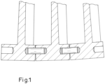
- US7984548 teaches providing (i) blind-holes in longitudinal faces of the bases such that the blind-holes are aligned along their axes, and (ii) pins for assembling into two blind-holes in the bases of adjacent vane units in a stage thus connecting the two vane units (see Fig. 1 ).
- DE102007059220 discloses a guide vane ring for thermal turbomachines, in particular aircraft engines, wherein guide vane feet of the guide vanes have grooves. Thereby, a ring element is positioned in a ring groove formed by the grooves of all the guide vane feet, which ring groove is open on one side for insertion of the ring element.
- All vane units in a stage may so be connected through the pins to form a vane ring, or at least halve a ring in a first halve of the casing.
- a disadvantage of the prior art method is that the robustness of the vane ring is not very controllable. For instance, the tightness of the fit between adjacent vane units in the vane ring may vary, resulting in sub-optimal damping characteristics and thus in wear and chatter over time.
- the invention provides a vane assembly according to claim 1.
- the invention overcomes the variability in fitting the vane units in a vane ring, thus providing a more robust ring with improved damping characteristics. More in particular, the invention allows clamping the individual vane units on a single shared connecting part, the lacing bar, which thus functions as the robust back bone of the assembly.
- the through-holes of adjacent vane units together form a cavity, wherein the cavity and the lacing bar have distinct/dissimilar arcuate shapes (i.e. have different radii of curvature) for providing a predefined tension in a vane assembly.
- the dissimilar arcuate form factors of the cavity formed by the through-holes and the lacing bar enable the vane assembly to be constructed with a predefined and reproducible tension causing the vane units to be clamped on the lacing bar.
- the variability present in the prior art solution is drastically diminished. This reduced variability improves the damping characteristics and thus minimizes wear of the vane units.
- the cross section of the lacing bar can be dimensioned to create a predefined spring force when it is inserted in the assembled units.
- the lacing bar - in contrast to the pin of the prior art - will be elastically deformed through bending upon insertion into and through the through-holes, thus providing the tension for reproducibly interconnecting the vane units in the assembly.
- the through-holes in adjacent vane units within the assembly are straight and together form a polygonal cavity in, respectively through, which the lacing bar is insertable.
- this overcomes the difficulty of machining the prior art blind-holes which are angled relative to the longitudinal base faces to accommodate the curvature of the casing slot.
- More sophisticated vane unit bases are trapezoidal allowing abutting the longitudinal base faces of adjacent units in the assembly, and (optionally) have adapted bottom faces congruent with the slot curvature.
- the lacing bar comprises a predefined arcuate shape for providing a predefined tension in a vane assembly.
- the predefined arcuate shape of the lacing bar enables providing a predefined and reproducible tension.
- the arcuate shape of the lacing bar enables easy and convenient assembly of vane units positioned in the slot and the lacing bar into a vane assembly.
- the arcuate shape of the lacing bar comprises a radius of curvature which deviates > 0% to 60% from an average radius of curvature of the through-holes (e.g. the polygonal cavity), preferably 10% to 50%, more preferably 20% to 40%.
- the elasticity of the lacing bar provides the predefined tension in the vane assembly for clamping the vane units to the lacing bar. Moreover, this allows for the vane units in the vane assembly to be pushed tight with their base protrusions into the longitudinal grooves in the slot side walls. Consequently, this improves the damping characteristics of the vane assembly and minimizes wear.
- the lacing bar has a length corresponding with the length of a slot in the (half-) casing of a compressor.
- a lacing bar length allows connecting the vane units of (half) a vane ring into a single assembly.
- this allows for forming a single assembly from all, or half, the vane units of a vane ring.
- the single assembly can be fitted in a casing slot in a well-controlled fashion improving the damping characteristics and thus minimizing wear.
- the lacing bar comprises a plurality of lacing bar components.
- this allows advanced options to define the desired tension and adjust it to the specifics of the compressor specifications. Consequently, this improves the compressor specific damping characteristics of the vane assembly and minimizes wear.
- the lacing bar components have end sections enabling engagement with a second lacing bar component for forming a combined vane assembly from a first and second vane assembly.
- multiple lacing bars may be used to assemble a plurality of vane assemblies into a vane ring, enabling easier mounting by maintenance staff.
- the end sections are selected from the group consisting of (i) slot & tongue end sections, (ii) hole & plug end sections, (iii) overlapping end sections, (iv) oblique end sections, and (v) flat end sections.
- the shape of the end sections is designed to promote contact between a first and second lacing bar component for improving the damping characteristics of a combined vane assembly.
- the interconnecting end sections are especially advantageous at the split line of two half-casings of an axial gas turbine compressor to engage and interlock the vane assemblies in each half to form a single integrated vane ring building a stage of the compressor.
- the lacing bar and/or the lacing bar components comprise a plurality of members together forming the lacing bar, respectively the lacing bar component.
- the members allow advanced options to define the desired tension and adjust it to the specifics of the compressor specifications.
- each vane unit base comprises a plurality of through holes positioned between its longitudinal faces
- the vane assembly comprises a plurality of lacing bars, each lacing bar arranged in the assembly through a corresponding through hole of the plurality of through holes, for creating a predefined tension.
- this allows each vane unit to be clamped to more than one lacing bar (such as two, three, or four) further reducing the variability in connecting the vane units to a single robust assembly.
- this allows for the vane units in the vane assembly to be pushed tight with their base protrusions into the semi-circular longitudinal grooves in the slot side walls. Consequently, incorporating a plurality of lacing bars improves the damping characteristics of the vane assembly and minimizes wear.
- the through-holes in the vane unit bases comprise a bushing or lining.
- the bushing and lining inside the through-hole improve the damping and wear characteristics of the assembly.
- the invention provides a method for assembling a vane assembly according to claim 9.
- engagement feature may also constitute a “disengagement feature”.
- disengagement feature may also constitute a “disengagement feature”. Skilled artisans will therefore understand that any of the preceding terms so used may be interchanged under appropriate circumstances such that various embodiments of the invention described herein, for example, are capable of operation in other configurations and/or orientations than those explicitly illustrated or otherwise described.
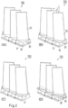
- FIG. 2 perspective views of a vane assembly 100 according to the invention for use in axial gas turbine compressors are shown.
- Fig.2A shows a vane assembly comprising three vane units 1 connected with a lacing bar 30.
- Each vane unit 1 has a base 10 and an airfoil 20 extending from it for cooperating with airfoils of a blade unit on a compressor rotor.
- the vane unit bases have bottom faces for engaging the casing slot.
- Protrusions 11 extend from transversal faces of base 1 for engagement with a cooperating groove in a side wall of a casing slot (not shown) into which the vane units 1 are to be positioned.
- through-holes 12 may be machined or cast for engagement with a lacing bar 30.
- lacing bar 30 will be inserted into and through a through-hole 12 of base 10.
- a vane assembly 100 is formed by lacing a plurality, such as two, three, four, or more, vane units 10 together through inserting a lacing bar 30 into and through the respective through-holes.
- Fig. 2D shows the possibility of providing a plurality of through-holes 12 (here two) in a vane unit base 10 for connecting the vane units 1 into a vane assembly 100.
- Each of the plurality of through holes is positioned between the two opposing longitudinal faces of base 10.
- a plurality of lacing bars 30, such as two, three, or four, may be inserted into respective through holes.
- lacing the vane units 1 together into assembly 100 using a lacing bar 30 overcomes the variability in fitting the vane units in a vane ring, thus providing a more robust ring with improved damping characteristics.
- Figure 3 provides side views of assembly 100 from a transversal ( Fig.3A ) and longitudinal ( Fig. 3B ) perspective.
- Fig. 3C provides a cross sectional view along the line A-A of Fig. 3B .
- the compressor casing of gas turbines usually comprises two semi-circular portions that are fitted together to encircle the rotor, the stator vanes units are assembled in vane ring segments for forming the stages of the compressor.
- a semi-circular slot in the two casing portions is arranged for engaging with the vane bases 10, such that the airfoils 20 extend radially inward towards the shaft of the compressor rotor.
- the vane units are thus positioned on a semi-circle as is indicated in Fig. 3 with the slight curvature of the bases 10 in vane assembly 100.
- Lacing bar 30 has an arcuate shape too, for easy assembly into the through-holes of the plurality of vane units 1 in assembly 100.
- Vane unit bases 10 may be machined or cast in a rectangular form. This however results in an inferior matching of adjacent vane units 1 and of the vane units and the casing slot. Hence, the vane units 1 are formed trapezoidal to match the longitudinal faces of adjacent vane units 1. Moreover, the units may have adapted bottom faces congruent with the slot curvature.
- the through-holes 12 in the vane bases 10 together form a cavity when the vane units 1 are positioned adjacent to each other in assembly 100 in the semi-circular slot. Consequently, the cavity has an arcuate shape.
- the cavity has an arcuate shape distinct from that of lacing bar 30.
- the radius of curvature of the arcuate shape of lacing bar 30 may be larger, equal (as long as the arcuate shape is distinct), or smaller than the (average) radius of curvature of the cavity formed by the through holes of a number of adjacent vane units 1.
- the arcuate shape of lacing bar 30 may comprises a radius of curvature which deviates > 0% to -60% from that of the through holes, preferably 20% to 50%, more preferably 30% to 40%.
- the radius of curvature of the arcuate shape of lacing bar 30 is smaller.
- the through-holes are straight for easy machining and/or casting.
- the through-holes 12 of adjacent vane units build a polygonal cavity into which lacing bar 30 is insertable, as can be seen in Fig.4 .
- the difference between the radius of curvature of the arcuate shape of lacing bar 30 and the average radius of curvature of the polygonal cavity results in an elastic bending deformation of lacing bar 30, as indicated by the forces F 1 and F 2 in Fig. 4 .
- the elastically bend lacing bar 30 improves the damping characteristics of the vane assembly. Hence, wear of the vane bases 10 and casing slot is reduced.
- arranging the lacing bar and the through holes in the respective bases such that the lacing bar is elastically deformed, respectively bend, when inserted into and through the through-holes causes each individual vane unit to be clamped onto the lacing bar.
- the forces F 1 and F 2 may be chosen in accordance with the specification of the compressor.
- the tension provided by lacing bar 30 is dimensioned by selecting, amongst others, an appropriate difference in radius of curvature, material, cross-sectional size and form factor, and/or configuration of lacing bar 30.
- all parts and features of the vane assembly 100 and its components i.e. vane unit 1, base 10, through hole 12, lacing bar 30
- the vane assembly can then be mounted in the slot without elastic stresses between the assembly and the casing.
- the internal stresses on the lacing bar 30 remain unchanged and well-defined, and thus the clamped vane units on the lacing bar back bone remain robustly secured.
- inserting the vane assembly in the slot is more convenient for operating personnel.
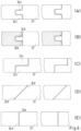
- lacing bar 30 may be cylindrical (5A), may have a rectangular (5B), such as a square, or a polygonal (5C & 5F) cross section, such as a hexagon or cross.
- lacing bar 30 may comprise a plurality of members 33 for tuning the resilient characteristics of the lacing bar.
- a cylindrical lacing bar may be formed by two halves (5D), four quarters (5E) or any number of pie-shaped members.
- a cross shaped lacing bar 30 may comprise a plurality of rectangular members (5F).
- the lacing bar members 33 may comprise different materials.
- the material of lacing bar 30 and/or lacing bar members 33 is chosen from the class of ferritic-martensitic stainless steels, and is close to the composition of the material from which the vane units 1 are manufactured.
- austenitic stainless steels, duplex steels, or other materials, and combinations thereof, may be used to benefit from different thermal expansion characteristics.
- the vane assembly 100 may be assembled with a lacing bar (30) having a length corresponding with a length of the slot in the compressor casing for connecting the vane units (1) of (halve) a vane ring into a single assembly (100).
- lacing bar 30 may comprise lacing bar components 31 that in lengthwise combination form lacing bar 30.
- the lacing bar components allow for easier insertion into the through holes, especially when the assembly is performed "in the field".
- the lacing bar components 31 comprise end sections 32 allowing two adjacent components to engage for forming a single assembly 100 from a first and second assembly. To this purpose end sections 32 may be formed such that two adjacent components interlock inside the cavity formed by through-holes 12.
- FIG. 5G & 5H Several examples of appropriately formed end sections 32 are depicted in Figs. 5G & 5H , as well as in Fig. 6 .
- the latter figure shows end sections 32 from the type (i) slot & tongue end sections (6A), (ii) hole & plug or pin end sections (6B), (iii) overlapping end sections (6C), (iv) oblique end sections (6D), and (v) flat or butt end sections (6E).
- lacing bars 30 will preferably connect 3 to 6 vane units 1 into a vane assembly 100.
- the length of a vane unit is typically between 30 mm and 90 mm.
- the length of a lacing bar 30 (or lacing bar component 31) ranges from 90 mm to 540 mm.
- the lacing bar 30 could extend up to the length of the casing slot, which in dependence of the specification of the compressor ranges between about 1000 mm and about 4000 mm (semi-circle) for casing diameters of utility gas turbines in the range of 600 mm to 2500 mm.
- the typical diameter for lacing bar 30 ranges between 4 and 14 mm, preferably between 6 and 10 mm. This dimension may be chosen in relation to the actual geometry of the vanes unit bases 10.
- the through-hole 12 may have a circular cross-section and forms a circumferential polygonal cavity in the vane units 1 of vane assembly 100.
- through-holes 12 may have differently shaped cross-sections, such as a polygonal cross-section.
- lacing bar 30 will have a cross-section congruent with the cross section of through-holes 12.
- it may, however, have other cross sections, for instance polygonal, such as square, rectangular, hexagonal, etc.
- lacing bar 30 or lacing bar components 31 may be composed of one or more members 33, for instance a plurality of pie-shaped members, that fill the desired cross section of the lacing bar or lacing bar component.
- the tension created by the assembly of the lacing bar 30 into the vane assembly 100 will be in the range of 500 N to 5000 N.
- the designed tension is realized through many factors, including but not limited to,
- through-holes 12 may be lined, for example with a bushing or other appropriate lining component or coating.
- the lining improves the damping and wear characteristics of vane assembly 100, thus improving the effective operational life of the gas turbine compressor in which the invention is implemented.
- a vane assembly comprising a vane unit (1) and a lacing bar (30), wherein the vane unit comprises a base (10) having a through-hole (12) positioned between opposing longitudinal faces of the base, wherein the lacing bar is arranged through the through hole, and wherein the lacing bar and through holes are arranged such that the lacing bar is elastically deformed, respectively bend, in an arcuate shape when inserted into and through the through-hole for clamping the vane unit onto the lacing bar.
Landscapes
- Engineering & Computer Science (AREA)
- Mechanical Engineering (AREA)
- General Engineering & Computer Science (AREA)
- Structures Of Non-Positive Displacement Pumps (AREA)
- Turbine Rotor Nozzle Sealing (AREA)
- Rotary Pumps (AREA)
Claims (9)
- Schaufelanordnung (100), umfassend eine Vielzahl von Schaufeleinheiten (1) und ein Verbindungsteil, das einen Schnürstab (30) umfasst, wobei jede der in Umfangsrichtung angeordneten Schaufeleinheiten an ihrem Aussenumfang eine Basis (10) umfasst, wobei sich Längsbasisflächen benachbarter Schaufeleinheiten in Umfangsrichtung gegenüberliegen, wobei die Basen (10) trapezförmig sind, was das Anliegen der benachbarten Längsbasisflächen ermöglicht, wobei jede Basis (10) ein Durchgangsloch (12) aufweist, das sich zwischen gegenüberliegenden Längsflächen der Basis erstreckt, und wobei bei der Anordnung die Durchgangslöcher (12) benachbarter Schaufeleinheiten gerade sind und zusammen einen polygonalen Umfangshohlraum bilden, wobei der Schnürstab (30) so ausgebildet ist, dass er in und durch die Durchgangslöcher (12) zum Koppeln von mindestens zwei benachbarten Schaufeleinheiten (1) in die Schaufelanordnung (100) einsetzbar ist, wobei, wenn zusammengebaut, der Schnürstab (30) durch die Durchgangslöcher der Vielzahl von Schaufeleinheiten angeordnet ist, wobei der Hohlraum und der Schnürstab (30) unterschiedliche bogenförmige Formen aufweisen, und wobei eine Differenz zwischen einem Krümmungsradius der bogenförmigen Form des Schnürstabs (30) und einem durchschnittlichen Krümmungsradius des polygonalen Hohlraums zu einer elastischen Biegeverformung des Schnürstabs (30), wenn eingesetzt, führt, so dass jede einzelne Schaufeleinheit (1) mittels einer Presspassung auf den Schnürstab geklemmt wird, wobei die Presspassung durch radial nach innen und aussen gerichtete Biegekräfte (F1, F2) erzeugt wird, die in inneren und äusseren Kontaktbereichen zwischen dem Schnürstab und den geraden Durchgangslöchern (12) induziert werden, wobei die radialen Kräfte durch Auswählen einer geeigneten Differenz in Krümmungsradius, Material, Querschnittsgrösse und/oder Formfaktor zwischen den Presspassungskomponenten der Schaufelanordnung (100) vordefiniert werden.
- Schaufelanordnung nach Anspruch 1, wobei die bogenförmige Form des eingesetzten Schnürstabs (30) einen Krümmungsradius umfasst, der > 0 % bis 60 % vom durchschnittlichen Krümmungsradius des durch die Durchgangslöcher (12) gebildeten Hohlraums abweicht, vorzugsweise 10 % bis 50 %, bevorzugter 20 % bis 40 %.
- Schaufelanordnung nach Anspruch 1, wobei der Schnürstab (30) eine Länge aufweist, die so konfiguriert ist, dass sie einer Länge eines Schlitzes in einem Gehäuse eines Verdichters entspricht, und zum Verbinden der Schaufeleinheiten (1) eines Schaufelrings des Verdichters zu einer einzigen Anordnung (100).
- Schaufelanordnung nach Anspruch 1, wobei der Schnürstab (30) eine Vielzahl von Schnürstabkomponenten (31) umfasst.
- Schaufelanordnung nach Anspruch 4, wobei die Schnürstabkomponenten Endabschnitte (32) aufweisen, die einen Eingriff mit einer zweiten Schnürstabkomponente (31) zum Bilden einer kombinierten Schaufelanordnung (100) aus einer ersten und zweiten Schaufelanordnung (100) ermöglichen.
- Schaufelanordnung nach Anspruch 5, wobei die Endabschnitte (32) ausgewählt sind aus der Gruppe bestehend aus (i) Schlitz- und Federendabschnitten (32a), (ii) Loch- und Stopfenendabschnitten (32b), (iii) überlappenden Endabschnitten (32c), (iv) schrägen Endabschnitten (32d) und (v) flachen Endabschnitten (32e).
- Schaufelanordnung nach den Ansprüchen 5 - 6, wobei der Schnürstab (30) und/oder die Schnürstabkomponenten (31) im Querschnitt eine Vielzahl von Schnürstabelementen (33) umfassen, die aus verschiedenen Materialien ausgewählt sind, vorzugsweise aus der Klasse der ferritischmartensitischen rostfreien Stähle.
- Schaufelanordnung nach Anspruch 1, wobei jede Schaufeleinheitsbasis eine Vielzahl von Durchgangslöchern umfasst, die sich zwischen ihren Längsflächen erstrecken, und wobei die Schaufelanordnung (100) eine Vielzahl von Schnürstäben (30) umfasst, wobei jeder Schnürstab in der Anordnung durch ein entsprechendes Durchgangsloch der Vielzahl von Durchgangslöchern angeordnet ist.
- Verfahren zum Zusammenbauen einer Schaufelanordnung (100) nach Anspruch 1, umfassend die Schritte (i) Bereitstellen der Vielzahl von Schaufeleinheiten (1), (ii) Positionieren der Schaufeleinheiten so, dass sich die Längsbasisflächen benachbarter Schaufeleinheiten in Umfangsrichtung gegenüberliegen, und so, dass die geraden Durchgangslöcher (12) benachbarter Schaufeleinheiten zusammen den polygonalen Umfangshohlraum bilden, und (iii) Einsetzen des Schnürstabs (30) durch die Durchgangslöcher benachbarter Schaufeleinheiten zum Koppeln der benachbarten Schaufeleinheiten in die Schaufelanordnung (100) so, dass die Differenz zwischen dem Krümmungsradius der bogenförmigen Form des Schnürstabs (30) und dem durchschnittlichen Krümmungsradius des polygonalen Hohlraums zu einer elastischen Biegeverformung des Schnürstabs (30) führt, so dass jede einzelne Schaufeleinheit (1) mittels einer Presspassung auf den Schnürstab geklemmt wird, wobei die Presspassung durch radial nach innen und aussen gerichtete Biegekräfte (F1, F2) erzeugt wird, die in inneren und äusseren Kontaktbereichen zwischen dem Schnürstab und den geraden Durchgangslöchern (12) induziert werden.
Applications Claiming Priority (2)
| Application Number | Priority Date | Filing Date | Title |
|---|---|---|---|
| EP17192214 | 2017-09-20 | ||
| PCT/EP2018/075018 WO2019057655A1 (en) | 2017-09-20 | 2018-09-17 | SET OF DAWN UNITS |
Publications (2)
| Publication Number | Publication Date |
|---|---|
| EP3685019A1 EP3685019A1 (de) | 2020-07-29 |
| EP3685019B1 true EP3685019B1 (de) | 2025-05-28 |
Family
ID=59966583
Family Applications (1)
| Application Number | Title | Priority Date | Filing Date |
|---|---|---|---|
| EP18770019.0A Active EP3685019B1 (de) | 2017-09-20 | 2018-09-17 | Verbindung von leitschaufelelementen |
Country Status (6)
| Country | Link |
|---|---|
| US (1) | US11428106B2 (de) |
| EP (1) | EP3685019B1 (de) |
| JP (1) | JP7264881B2 (de) |
| CN (1) | CN111315963B (de) |
| SA (1) | SA520411568B1 (de) |
| WO (1) | WO2019057655A1 (de) |
Families Citing this family (3)
| Publication number | Priority date | Publication date | Assignee | Title |
|---|---|---|---|---|
| FR3137122B1 (fr) * | 2022-06-22 | 2024-06-21 | Safran Aircraft Engines | Ensemble aubagé à liaison inter-plateformes par organe de friction |
| US12025053B1 (en) | 2023-07-06 | 2024-07-02 | Pratt & Whitney Canada Corp. | Cantilever stator vane with damper |
| US20260028913A1 (en) * | 2024-07-25 | 2026-01-29 | Kenneth Knecht | Gas turbine compressor stator blade |
Family Cites Families (19)
| Publication number | Priority date | Publication date | Assignee | Title |
|---|---|---|---|---|
| US900739A (en) * | 1907-05-10 | 1908-10-13 | Belliss & Morcom Ltd | Turbine. |
| US1061648A (en) * | 1910-08-27 | 1913-05-13 | George Westinghouse | Blades. |
| BE459482A (de) | 1943-10-05 | |||
| FR1033197A (fr) | 1951-02-27 | 1953-07-08 | Rateau Soc | Amortisseurs de vibrations pour aubages mobiles de turbo-machines |
| FR69842E (fr) | 1956-05-30 | 1958-12-30 | Rateau Soc | Amortisseurs de vibrations pour aubages mobiles de turbo-machines |
| CH578679A5 (en) | 1974-05-31 | 1976-08-13 | Bbc Sulzer Turbomaschinen | Damping wire for turbine rotor blades - is held in blade wedging holes for making contact on rotation |
| JPS5996301U (ja) | 1982-12-21 | 1984-06-29 | 株式会社東芝 | タ−ビン動翼の連結構造 |
| US5022818A (en) | 1989-02-21 | 1991-06-11 | Westinghouse Electric Corp. | Compressor diaphragm assembly |
| DE29701592U1 (de) * | 1996-02-05 | 1997-03-27 | Asea Brown Boveri Ag, Baden, Aargau | Thermische Strömungsmaschine |
| FI100821B (fi) | 1996-02-28 | 1998-02-27 | Wartsila Diesel Internat Ltd O | Järjestely kaasuturbiinin tai vastaavan siipien värähtelyjen vaimentam iseksi |
| JPH10325302A (ja) | 1997-05-26 | 1998-12-08 | Ishikawajima Harima Heavy Ind Co Ltd | 動翼の制振構造 |
| DE19913265A1 (de) | 1999-03-24 | 2000-09-28 | Asea Brown Boveri | Turbomaschinenschaufel |
| US7651319B2 (en) | 2002-02-22 | 2010-01-26 | Drs Power Technology Inc. | Compressor stator vane |
| JP5091615B2 (ja) | 2007-10-15 | 2012-12-05 | 三菱重工業株式会社 | 静翼環セグメントの組立方法、静翼環セグメント、結合部材、溶接方法 |
| DE102007059220A1 (de) | 2007-12-07 | 2009-06-10 | Rolls-Royce Deutschland Ltd & Co Kg | Leitschaufelkranz für thermische Strömungsmaschinen, insbesondere Flugtriebwerke |
| JP5030813B2 (ja) * | 2008-02-20 | 2012-09-19 | 三菱重工業株式会社 | ブリスク |
| ATE548542T1 (de) | 2008-12-24 | 2012-03-15 | Techspace Aero Sa | Leitschaufelstufe eines verdichters, entsprechender verdichter und verfahren zur sicherung von schaufeln in einer solchen leitschaufelstufe |
| US8905717B2 (en) * | 2010-10-06 | 2014-12-09 | General Electric Company | Turbine bucket lockwire rotation prevention |
| JP5665724B2 (ja) | 2011-12-12 | 2015-02-04 | 株式会社東芝 | 静翼翼列、静翼翼列の組立方法および蒸気タービン |
-
2018
- 2018-09-17 EP EP18770019.0A patent/EP3685019B1/de active Active
- 2018-09-17 WO PCT/EP2018/075018 patent/WO2019057655A1/en not_active Ceased
- 2018-09-17 US US16/645,013 patent/US11428106B2/en active Active
- 2018-09-17 CN CN201880060917.7A patent/CN111315963B/zh active Active
- 2018-09-17 JP JP2020514621A patent/JP7264881B2/ja active Active
-
2020
- 2020-03-19 SA SA520411568A patent/SA520411568B1/ar unknown
Also Published As
| Publication number | Publication date |
|---|---|
| US11428106B2 (en) | 2022-08-30 |
| US20200256199A1 (en) | 2020-08-13 |
| JP7264881B2 (ja) | 2023-04-25 |
| SA520411568B1 (ar) | 2022-08-09 |
| CN111315963A (zh) | 2020-06-19 |
| WO2019057655A1 (en) | 2019-03-28 |
| EP3685019A1 (de) | 2020-07-29 |
| CN111315963B (zh) | 2023-03-24 |
| JP2020534466A (ja) | 2020-11-26 |
Similar Documents
| Publication | Publication Date | Title |
|---|---|---|
| EP3685019B1 (de) | Verbindung von leitschaufelelementen | |
| EP3023580B1 (de) | Gasturbine mit mehreren zugstangen und verfahren zur montage davon | |
| KR101994511B1 (ko) | 노즐 링 | |
| US8376692B2 (en) | Turbo compressor in an axial type of construction | |
| US10215036B2 (en) | Blade attachment assembly | |
| EP2532835B1 (de) | Sperrsystem für Turbomaschinenschaufeln | |
| RU2666836C2 (ru) | Способ сборки ступени статора газотурбинного двигателя | |
| US7144218B2 (en) | Anti-rotation lock | |
| KR102170572B1 (ko) | 터보기계 로터 조립체 및 방법 | |
| US7708529B2 (en) | Rotor of a turbo engine, e.g., a gas turbine rotor | |
| EP3123002A1 (de) | Leitschaufelträgersystem in einem gasturbinenmotor | |
| CN102220885A (zh) | 用于周向附接装置的锁定组件 | |
| US20150010395A1 (en) | Stator Blade Sector for an Axial Turbomachine with a Dual Means of Fixing | |
| JP4439239B2 (ja) | 支持体の水平接合面におけるタービンノズル保持装置 | |
| EP3409898B1 (de) | Bauchbanddichtungen und verfahren | |
| KR20150050472A (ko) | 터빈 노즐 고정 방법 및 시스템 | |
| EP1757772A2 (de) | Aufgestapelter Dampfgang für Dampfturbinen | |
| US20150003979A1 (en) | Steam turbine nozzle vane arrangement and method of manufacturing | |
| US20180195399A1 (en) | Rotor blade arrangement having elastic support elements for a thermal turbomachine | |
| EP1443179B1 (de) | Ein Rotor mit Schaufelhalteplatten | |
| RU2184879C1 (ru) | Направляющий аппарат осевого компрессора | |
| JP2024077838A (ja) | タービン動翼の固定構造 | |
| GB2566635A (en) | Assembly for attaching a nozzle to a structural element of a turbine engine | |
| US11525363B2 (en) | Turbine wheel and wire retention pin fixation method for turbine wheel | |
| KR101872808B1 (ko) | 길이조절구조를 포함하는 가스터빈 로터, 및 이를 포함하는 가스터빈 |
Legal Events
| Date | Code | Title | Description |
|---|---|---|---|
| STAA | Information on the status of an ep patent application or granted ep patent |
Free format text: STATUS: UNKNOWN |
|
| STAA | Information on the status of an ep patent application or granted ep patent |
Free format text: STATUS: THE INTERNATIONAL PUBLICATION HAS BEEN MADE |
|
| PUAI | Public reference made under article 153(3) epc to a published international application that has entered the european phase |
Free format text: ORIGINAL CODE: 0009012 |
|
| STAA | Information on the status of an ep patent application or granted ep patent |
Free format text: STATUS: REQUEST FOR EXAMINATION WAS MADE |
|
| 17P | Request for examination filed |
Effective date: 20200420 |
|
| AK | Designated contracting states |
Kind code of ref document: A1 Designated state(s): AL AT BE BG CH CY CZ DE DK EE ES FI FR GB GR HR HU IE IS IT LI LT LU LV MC MK MT NL NO PL PT RO RS SE SI SK SM TR |
|
| AX | Request for extension of the european patent |
Extension state: BA ME |
|
| DAV | Request for validation of the european patent (deleted) | ||
| DAX | Request for extension of the european patent (deleted) | ||
| STAA | Information on the status of an ep patent application or granted ep patent |
Free format text: STATUS: EXAMINATION IS IN PROGRESS |
|
| 17Q | First examination report despatched |
Effective date: 20210125 |
|
| GRAP | Despatch of communication of intention to grant a patent |
Free format text: ORIGINAL CODE: EPIDOSNIGR1 |
|
| STAA | Information on the status of an ep patent application or granted ep patent |
Free format text: STATUS: GRANT OF PATENT IS INTENDED |
|
| INTG | Intention to grant announced |
Effective date: 20241217 |
|
| GRAS | Grant fee paid |
Free format text: ORIGINAL CODE: EPIDOSNIGR3 |
|
| P01 | Opt-out of the competence of the unified patent court (upc) registered |
Free format text: CASE NUMBER: APP_13270/2025 Effective date: 20250318 |
|
| GRAA | (expected) grant |
Free format text: ORIGINAL CODE: 0009210 |
|
| STAA | Information on the status of an ep patent application or granted ep patent |
Free format text: STATUS: THE PATENT HAS BEEN GRANTED |
|
| AK | Designated contracting states |
Kind code of ref document: B1 Designated state(s): AL AT BE BG CH CY CZ DE DK EE ES FI FR GB GR HR HU IE IS IT LI LT LU LV MC MK MT NL NO PL PT RO RS SE SI SK SM TR |
|
| REG | Reference to a national code |
Ref country code: GB Ref legal event code: FG4D |
|
| REG | Reference to a national code |
Ref country code: CH Ref legal event code: EP |
|
| REG | Reference to a national code |
Ref country code: IE Ref legal event code: FG4D Ref country code: DE Ref legal event code: R096 Ref document number: 602018082282 Country of ref document: DE |
|
| REG | Reference to a national code |
Ref country code: NL Ref legal event code: MP Effective date: 20250528 Ref country code: CH Ref legal event code: U11 Free format text: ST27 STATUS EVENT CODE: U-0-0-U10-U11 (AS PROVIDED BY THE NATIONAL OFFICE) Effective date: 20251001 |
|
| PG25 | Lapsed in a contracting state [announced via postgrant information from national office to epo] |
Ref country code: ES Free format text: LAPSE BECAUSE OF FAILURE TO SUBMIT A TRANSLATION OF THE DESCRIPTION OR TO PAY THE FEE WITHIN THE PRESCRIBED TIME-LIMIT Effective date: 20250528 Ref country code: FI Free format text: LAPSE BECAUSE OF FAILURE TO SUBMIT A TRANSLATION OF THE DESCRIPTION OR TO PAY THE FEE WITHIN THE PRESCRIBED TIME-LIMIT Effective date: 20250528 |
|
| REG | Reference to a national code |
Ref country code: LT Ref legal event code: MG9D |
|
| PG25 | Lapsed in a contracting state [announced via postgrant information from national office to epo] |
Ref country code: NO Free format text: LAPSE BECAUSE OF FAILURE TO SUBMIT A TRANSLATION OF THE DESCRIPTION OR TO PAY THE FEE WITHIN THE PRESCRIBED TIME-LIMIT Effective date: 20250828 Ref country code: GR Free format text: LAPSE BECAUSE OF FAILURE TO SUBMIT A TRANSLATION OF THE DESCRIPTION OR TO PAY THE FEE WITHIN THE PRESCRIBED TIME-LIMIT Effective date: 20250829 |
|
| PG25 | Lapsed in a contracting state [announced via postgrant information from national office to epo] |
Ref country code: PL Free format text: LAPSE BECAUSE OF FAILURE TO SUBMIT A TRANSLATION OF THE DESCRIPTION OR TO PAY THE FEE WITHIN THE PRESCRIBED TIME-LIMIT Effective date: 20250528 Ref country code: NL Free format text: LAPSE BECAUSE OF FAILURE TO SUBMIT A TRANSLATION OF THE DESCRIPTION OR TO PAY THE FEE WITHIN THE PRESCRIBED TIME-LIMIT Effective date: 20250528 |
|
| PG25 | Lapsed in a contracting state [announced via postgrant information from national office to epo] |
Ref country code: BG Free format text: LAPSE BECAUSE OF FAILURE TO SUBMIT A TRANSLATION OF THE DESCRIPTION OR TO PAY THE FEE WITHIN THE PRESCRIBED TIME-LIMIT Effective date: 20250528 |
|
| PG25 | Lapsed in a contracting state [announced via postgrant information from national office to epo] |
Ref country code: HR Free format text: LAPSE BECAUSE OF FAILURE TO SUBMIT A TRANSLATION OF THE DESCRIPTION OR TO PAY THE FEE WITHIN THE PRESCRIBED TIME-LIMIT Effective date: 20250528 |
|
| PGFP | Annual fee paid to national office [announced via postgrant information from national office to epo] |
Ref country code: FR Payment date: 20250922 Year of fee payment: 8 |
|
| PG25 | Lapsed in a contracting state [announced via postgrant information from national office to epo] |
Ref country code: RS Free format text: LAPSE BECAUSE OF FAILURE TO SUBMIT A TRANSLATION OF THE DESCRIPTION OR TO PAY THE FEE WITHIN THE PRESCRIBED TIME-LIMIT Effective date: 20250828 |
|
| PG25 | Lapsed in a contracting state [announced via postgrant information from national office to epo] |
Ref country code: IS Free format text: LAPSE BECAUSE OF FAILURE TO SUBMIT A TRANSLATION OF THE DESCRIPTION OR TO PAY THE FEE WITHIN THE PRESCRIBED TIME-LIMIT Effective date: 20250928 |
|
| PG25 | Lapsed in a contracting state [announced via postgrant information from national office to epo] |
Ref country code: LV Free format text: LAPSE BECAUSE OF FAILURE TO SUBMIT A TRANSLATION OF THE DESCRIPTION OR TO PAY THE FEE WITHIN THE PRESCRIBED TIME-LIMIT Effective date: 20250528 |
|
| REG | Reference to a national code |
Ref country code: AT Ref legal event code: MK05 Ref document number: 1798704 Country of ref document: AT Kind code of ref document: T Effective date: 20250528 |
|
| PG25 | Lapsed in a contracting state [announced via postgrant information from national office to epo] |
Ref country code: AT Free format text: LAPSE BECAUSE OF FAILURE TO SUBMIT A TRANSLATION OF THE DESCRIPTION OR TO PAY THE FEE WITHIN THE PRESCRIBED TIME-LIMIT Effective date: 20250528 Ref country code: SM Free format text: LAPSE BECAUSE OF FAILURE TO SUBMIT A TRANSLATION OF THE DESCRIPTION OR TO PAY THE FEE WITHIN THE PRESCRIBED TIME-LIMIT Effective date: 20250528 Ref country code: DK Free format text: LAPSE BECAUSE OF FAILURE TO SUBMIT A TRANSLATION OF THE DESCRIPTION OR TO PAY THE FEE WITHIN THE PRESCRIBED TIME-LIMIT Effective date: 20250528 |
|
| PGFP | Annual fee paid to national office [announced via postgrant information from national office to epo] |
Ref country code: CH Payment date: 20251001 Year of fee payment: 8 |
|
| PG25 | Lapsed in a contracting state [announced via postgrant information from national office to epo] |
Ref country code: CZ Free format text: LAPSE BECAUSE OF FAILURE TO SUBMIT A TRANSLATION OF THE DESCRIPTION OR TO PAY THE FEE WITHIN THE PRESCRIBED TIME-LIMIT Effective date: 20250528 |
|
| PG25 | Lapsed in a contracting state [announced via postgrant information from national office to epo] |
Ref country code: EE Free format text: LAPSE BECAUSE OF FAILURE TO SUBMIT A TRANSLATION OF THE DESCRIPTION OR TO PAY THE FEE WITHIN THE PRESCRIBED TIME-LIMIT Effective date: 20250528 |
|
| PG25 | Lapsed in a contracting state [announced via postgrant information from national office to epo] |
Ref country code: RO Free format text: LAPSE BECAUSE OF FAILURE TO SUBMIT A TRANSLATION OF THE DESCRIPTION OR TO PAY THE FEE WITHIN THE PRESCRIBED TIME-LIMIT Effective date: 20250528 Ref country code: SK Free format text: LAPSE BECAUSE OF FAILURE TO SUBMIT A TRANSLATION OF THE DESCRIPTION OR TO PAY THE FEE WITHIN THE PRESCRIBED TIME-LIMIT Effective date: 20250528 |
|
| PG25 | Lapsed in a contracting state [announced via postgrant information from national office to epo] |
Ref country code: IT Free format text: LAPSE BECAUSE OF FAILURE TO SUBMIT A TRANSLATION OF THE DESCRIPTION OR TO PAY THE FEE WITHIN THE PRESCRIBED TIME-LIMIT Effective date: 20250528 |