EP3684544B1 - Düse für einen plasmabrennerkopf, laserschneidkopf und plasma-laser-schneidkopf - Google Patents
Düse für einen plasmabrennerkopf, laserschneidkopf und plasma-laser-schneidkopf Download PDFInfo
- Publication number
- EP3684544B1 EP3684544B1 EP18792367.7A EP18792367A EP3684544B1 EP 3684544 B1 EP3684544 B1 EP 3684544B1 EP 18792367 A EP18792367 A EP 18792367A EP 3684544 B1 EP3684544 B1 EP 3684544B1
- Authority
- EP
- European Patent Office
- Prior art keywords
- nozzle
- longitudinal axis
- section
- range
- diameter
- Prior art date
- Legal status (The legal status is an assumption and is not a legal conclusion. Google has not performed a legal analysis and makes no representation as to the accuracy of the status listed.)
- Active
Links
Images


Classifications
-
- H—ELECTRICITY
- H05—ELECTRIC TECHNIQUES NOT OTHERWISE PROVIDED FOR
- H05H—PLASMA TECHNIQUE; PRODUCTION OF ACCELERATED ELECTRICALLY-CHARGED PARTICLES OR OF NEUTRONS; PRODUCTION OR ACCELERATION OF NEUTRAL MOLECULAR OR ATOMIC BEAMS
- H05H1/00—Generating plasma; Handling plasma
- H05H1/24—Generating plasma
- H05H1/26—Plasma torches
- H05H1/32—Plasma torches using an arc
- H05H1/34—Details, e.g. electrodes, nozzles
- H05H1/3405—Arrangements for stabilising or constricting the arc, e.g. by an additional gas flow
-
- B—PERFORMING OPERATIONS; TRANSPORTING
- B23—MACHINE TOOLS; METAL-WORKING NOT OTHERWISE PROVIDED FOR
- B23K—SOLDERING OR UNSOLDERING; WELDING; CLADDING OR PLATING BY SOLDERING OR WELDING; CUTTING BY APPLYING HEAT LOCALLY, e.g. FLAME CUTTING; WORKING BY LASER BEAM
- B23K10/00—Welding or cutting by means of a plasma
- B23K10/02—Plasma welding
-
- B—PERFORMING OPERATIONS; TRANSPORTING
- B23—MACHINE TOOLS; METAL-WORKING NOT OTHERWISE PROVIDED FOR
- B23K—SOLDERING OR UNSOLDERING; WELDING; CLADDING OR PLATING BY SOLDERING OR WELDING; CUTTING BY APPLYING HEAT LOCALLY, e.g. FLAME CUTTING; WORKING BY LASER BEAM
- B23K26/00—Working by laser beam, e.g. welding, cutting or boring
- B23K26/14—Working by laser beam, e.g. welding, cutting or boring using a fluid stream, e.g. a jet of gas, in conjunction with the laser beam; Nozzles therefor
- B23K26/1462—Nozzles; Features related to nozzles
-
- B—PERFORMING OPERATIONS; TRANSPORTING
- B23—MACHINE TOOLS; METAL-WORKING NOT OTHERWISE PROVIDED FOR
- B23K—SOLDERING OR UNSOLDERING; WELDING; CLADDING OR PLATING BY SOLDERING OR WELDING; CUTTING BY APPLYING HEAT LOCALLY, e.g. FLAME CUTTING; WORKING BY LASER BEAM
- B23K26/00—Working by laser beam, e.g. welding, cutting or boring
- B23K26/36—Removing material
- B23K26/38—Removing material by boring or cutting
-
- H—ELECTRICITY
- H05—ELECTRIC TECHNIQUES NOT OTHERWISE PROVIDED FOR
- H05H—PLASMA TECHNIQUE; PRODUCTION OF ACCELERATED ELECTRICALLY-CHARGED PARTICLES OR OF NEUTRONS; PRODUCTION OR ACCELERATION OF NEUTRAL MOLECULAR OR ATOMIC BEAMS
- H05H1/00—Generating plasma; Handling plasma
- H05H1/24—Generating plasma
- H05H1/26—Plasma torches
- H05H1/32—Plasma torches using an arc
- H05H1/34—Details, e.g. electrodes, nozzles
- H05H1/3484—Convergent-divergent nozzles
-
- H—ELECTRICITY
- H05—ELECTRIC TECHNIQUES NOT OTHERWISE PROVIDED FOR
- H05H—PLASMA TECHNIQUE; PRODUCTION OF ACCELERATED ELECTRICALLY-CHARGED PARTICLES OR OF NEUTRONS; PRODUCTION OR ACCELERATION OF NEUTRAL MOLECULAR OR ATOMIC BEAMS
- H05H1/00—Generating plasma; Handling plasma
- H05H1/24—Generating plasma
- H05H1/26—Plasma torches
- H05H1/32—Plasma torches using an arc
- H05H1/34—Details, e.g. electrodes, nozzles
- H05H1/3421—Transferred arc or pilot arc mode
-
- H—ELECTRICITY
- H05—ELECTRIC TECHNIQUES NOT OTHERWISE PROVIDED FOR
- H05H—PLASMA TECHNIQUE; PRODUCTION OF ACCELERATED ELECTRICALLY-CHARGED PARTICLES OR OF NEUTRONS; PRODUCTION OR ACCELERATION OF NEUTRAL MOLECULAR OR ATOMIC BEAMS
- H05H1/00—Generating plasma; Handling plasma
- H05H1/24—Generating plasma
- H05H1/26—Plasma torches
- H05H1/32—Plasma torches using an arc
- H05H1/34—Details, e.g. electrodes, nozzles
- H05H1/3478—Geometrical details
Definitions
- Plasma torches, laser cutting heads and plasma laser cutting heads are generally used for the thermal processing of electrically conductive materials such as steel and non-ferrous metals.
- Plasma torches usually consist of a torch body, an electrode, a nozzle and a holder for it. Modern plasma torches also have a nozzle protection cap mounted over the nozzle (see, for example, US2016037618 A1 ). A nozzle is often fixed using a nozzle cap.
- the components that wear out as a result of the high thermal load caused by the arc are in particular the electrode, the nozzle, the nozzle cap, the nozzle protection cap, the nozzle protection cap holder and the plasma gas guide and secondary gas guide parts. These components can be easily replaced by an operator and are therefore referred to as wearing parts.
- the plasma torches are connected via cables to a power source and a gas supply that feeds the plasma torch.
- the plasma torch can also be connected to a cooling device for a cooling medium, such as a cooling liquid.
- Plasma cutting torches are subject to high thermal loads. This is due to the strong constriction of the plasma jet by the nozzle bore. Small bores are used here so that high current densities of 50 to 150 A/mm 2 can be generated in the nozzle bore, high energy densities of approx. 2x10 6 W/cm 2 and high temperatures of up to 30,000 K. Furthermore, higher gas pressures, usually up to 12 bar, are used in the plasma cutting torch. The combination of high temperature and high kinetic energy of the plasma gas flowing through the nozzle bore leads to the workpiece melting and the melt being expelled. A kerf is created and the workpiece is separated.
- a high level of noise pollution occurs depending on the cutting current and current density in the nozzle and the gases used. This can be over 100 dB(A).
- the sound frequencies that humans can perceive are in the range of about 20 Hz to about 20,000 Hz. High frequencies (> 1,000 Hz) with large amplitudes are not only perceived as unpleasant, but can also have negative health effects without suitable protective equipment. If you record the frequencies of the sound during plasma cutting, you will find clear amplitudes between 1,000 Hz and 15,000 Hz.
- oxidizing gases are often used to cut unalloyed or low-alloy steels and non-oxidizing gases are used to cut high-alloy steels or non-ferrous metals.
- a plasma gas flows between the electrode and the nozzle.
- the plasma gas is guided through a gas guide part. This allows the plasma gas to be directed in a targeted manner. It is often set in rotation around the electrode by a radial and/or axial offset of the openings in the plasma gas guide part.
- the plasma gas guide part is made of electrically insulating material because the electrode and the nozzle must be electrically insulated from each other. This is necessary because the electrode and the nozzle have different electrical potentials during operation of the plasma cutting torch.
- an arc is generated between the electrode and the nozzle and/or the workpiece. which ionizes the plasma gas.
- a high voltage can be applied between the electrode and nozzle, which pre-ionizes the gap between the electrode and nozzle and thus creates an arc.
- the arc burning between the electrode and nozzle is also called the pilot arc.
- the pilot arc exits through the nozzle bore and hits the workpiece, ionizing the path to the workpiece. This allows the arc to form between the electrode and the workpiece. This arc is also known as the main arc.
- the pilot arc can be switched off during the main arc. However, it can also continue to operate. During plasma cutting, this is often switched off so as not to place additional strain on the nozzle.
- the electrode and nozzle in particular are subject to high thermal stress and must be cooled. At the same time, they must also conduct the electrical current required to form the arc. For this reason, materials that conduct heat well and are electrically conductive are used, usually metals such as copper, silver, aluminum, tin, zinc, iron or alloys that contain at least one of these metals.
- the electrode often consists of an electrode holder and an emission insert made of a material that has a high melting temperature ( ⁇ 2000°C) and a lower electron work function than the electrode holder.
- the materials used for the emission insert are non-oxidizing plasma gases such as argon, hydrogen, nitrogen, helium and mixtures thereof, tungsten, and when oxidizing gases such as oxygen, air and mixtures thereof, nitrogen-oxygen mixtures and mixtures with other gases are used, hafnium or zirconium.
- the high-temperature material can be fitted into an electrode holder made of a material that conducts heat and electricity well, for example by being pressed in with a positive and/or frictional fit.
- the electrode and nozzle can be cooled using gas, such as plasma gas or a secondary gas that flows along the outside of the nozzle.
- gas such as plasma gas or a secondary gas that flows along the outside of the nozzle.
- a liquid such as water
- the electrode and/or nozzle are often cooled directly with the liquid, i.e. the liquid is in direct contact with the electrode and/or nozzle.
- a nozzle cap is placed around the nozzle, the inner surface of which forms a coolant chamber with the outer surface of the nozzle, in which the coolant flows.
- Modern plasma cutting torches also have a nozzle protection cap outside the nozzle and/or nozzle cap.
- the inner surface of the nozzle protection cap and the outer surface of the nozzle or nozzle cap form a space through which a secondary or protective gas flows.
- the secondary or protective gas exits the bore of the nozzle protection cap and envelops the plasma jet, creating a defined atmosphere around it.
- the secondary gas also protects the nozzle and nozzle protection cap from arcs that can form between the jet and the workpiece. These are known as double arcs and can damage the nozzle.
- the nozzle and nozzle protection cap are subjected to heavy loads from hot material spraying up.
- the secondary gas the volume flow of which can be higher when piercing than when cutting, keeps the spraying material away from the nozzle and nozzle protection cap, thus protecting it from damage.
- the nozzle protection cap is also subject to high thermal stress and must be cooled. Therefore, materials that are good heat and electrical conductors are used, usually metals such as copper, silver, aluminum, tin, zinc, iron or alloys that contain at least one of these metals.
- the electrode and the nozzle can also be cooled indirectly.
- they are in contact with a component made of a material that conducts heat and electricity well, usually a metal, for example copper, silver, aluminium, tin, zinc, iron or Alloys that contain at least one of these metals, come into contact by touching.
- This component is in turn cooled directly, which means that it is in direct contact with the usually flowing coolant.
- These components can simultaneously serve as a holder or receptacle for the electrode, the nozzle, the nozzle cap or the nozzle protection cap and dissipate the heat and supply the current.
- the nozzle protection cap is usually only cooled by the secondary gas.
- the secondary gas cap is cooled directly or indirectly by a cooling liquid.
- plasma cutting results in high levels of noise pollution with sound pressure levels sometimes exceeding 100 dB(A) due to the high energy density and high flow rate of the plasma or plasma gas.
- the magnitude of the sound pressure level depends, among other things, on the electrical power with which the plasma is operated or on the cutting current, the cutting current density in the nozzle opening, the workpiece thickness and thus the arc length, the cutting speed and the plasma or secondary gases used.
- the noise pollution increases with higher power, higher cutting current, higher current density, greater workpiece thickness and longer arc length.
- Some plasma cutting technologies also produce a so-called whistling sound, which is perceived by the human ear as particularly unpleasant and loud. This occurs particularly when the plasma gas is set into high rotation, for example by a corresponding plasma gas guide.
- Laser cutting heads essentially consist of a body, an optical system in the body for focusing the laser beam, connections for the Laser light supply or the optical fiber, gas (cutting gas and secondary gas) and cooling medium and a nozzle with an opening that forms the gas jet of the cutting gas and through which the laser beam exits the laser cutting head.
- the laser beam hits a workpiece and is absorbed.
- the heated workpiece is melted and expelled (laser melting cutting) or oxidized (laser flame cutting).
- the laser cutting head may also have a nozzle protection cap outside the nozzle.
- the inner surface of the nozzle protection cap and the outer surface of the nozzle or nozzle cap form a space through which a secondary or protective gas flows.
- the secondary or protective gas exits the bore of the nozzle protection cap and envelops the laser beam, creating a defined atmosphere around it.
- the secondary gas also protects the nozzle.
- the nozzle is subjected to heavy loads from hot material spraying up.
- the secondary gas whose volume flow may be higher when piercing than when cutting, keeps the spraying material away from the nozzle and thus protects it from damage.
- Processing heads in which both plasma and laser cutting are used simultaneously so-called plasma laser cutting heads, have features of the plasma torch head and the laser cutting head. Here, the features and thus the advantages of both cutting processes are combined.
- the aim of the invention is to reduce noise pollution during plasma cutting, laser cutting (laser beam cutting) (with process gas) and in plasma laser cutting, if possible without impairing the cutting speed and cut quality.
- a nozzle for a plasma torch head, laser cutting head or plasma laser cutting head comprising a body with a longitudinal axis M, a front end, a rear end and a nozzle opening at the front end, wherein the nozzle opening at the front end, seen from the front end, comprises at least the following sections in longitudinal section: a first section A1 extending along the longitudinal axis M and tapering towards the rear end with an inner surface and a body edge at the front end and a second section A3 extending along the longitudinal axis M with an inner surface and a body edge at the transition from the first section A1 to the second section A3, wherein either the first section A1 does not taper linearly over its entire length and a virtual connecting line V1 between the body edge of the nozzle opening at the front end and the body edge at the transition from the first section A1 to the second section A3 and the longitudinal axis M forms an angle ⁇ 1 in a range from 15° to 40°, more preferably in a range
- the invention is provided such that at the transition or before or immediately before the transition from the first section A1 to the second section A3 there is at least one further inner surface 213 extending at an angle ⁇ to the longitudinal axis M in a range from 45° to 120°, more preferably in a range from 60° to 110°, even more preferably in a range from 80° to 100°, even more preferably in a range from 85° to 95°, most preferably vertically.
- the inner surface 213 is located between the body edge 203 and the inner surface 211, whereby a transition can be gradual or continuous.
- viewed from the front end after the second section A3 there is a third section A5 with an inner surface extending along the longitudinal axis M and widening towards the rear end.
- the inner surface of the third section A5 has at least one region widening along the longitudinal axis M in the direction of the rear end, the inner surface of which and the longitudinal axis M enclose an angle ⁇ in a range from 30° to 90°, more preferably in a range from 40° to 75°.
- a fourth section A7 with an inner surface is present and a virtual connecting line V4 between the body edge at the transition from the second section A3 to the third section A5 and the body inner edge at the transition from the third section A5 to the fourth section A7 and the longitudinal axis M enclose an angle ⁇ 1 in a range from 30° to 90°, more preferably in a range from 40° to 75° and/or the inner surface (224) of the third section A5 and the longitudinal axis M encloses an angle ⁇ in a range of 30° to 90°, more preferably in a range of 40° to 75°.
- a fourth section A7 with an inner surface, wherein the inner surface 227 of the fourth section A7 has at least one region which widens at an angle ⁇ to the longitudinal axis M in a range from 0° to 10°, preferably 5°, in the direction of the rear end 28 or tapers at an angle in a range from 170° to 180°, preferably 175°, in the direction of the rear end 28 or runs parallel to the longitudinal axis M, or wherein the inner surface 227 of the fourth section A7 widens at an angle ⁇ to the longitudinal axis M in a range from 0° to 10°, preferably 5°, in the direction of the rear end 28 or tapers at an angle in a range from 170° to 180°, preferably 175°, in the direction of the rear end 28 or runs parallel to the longitudinal axis M runs.
- a fourth section A7 with an inner surface is present, wherein the inner surface of the fourth section A7 widens at an angle ⁇ to the longitudinal axis M in a range of 0° to 10°, preferably 5°, towards the rear end or tapers at an angle in a range of 170° to 180°, preferably 175°, towards the rear end or runs parallel to the longitudinal axis M.
- a largest cross-sectional area A10 of the first section A1 and/or a largest cross-sectional area of the nozzle opening located directly at the front end of the nozzle opening is/are at least 1.7, preferably 2.1, times larger and/or a maximum of 4.0, preferably 3.7, times larger than a smallest cross-sectional area A30, A31 of the second section A3 and/or a smallest cross-sectional area A30, A31 of the nozzle opening.
- a largest diameter D1 of the first section A1 and/or a largest diameter D1 of the nozzle opening located directly at the front end of the nozzle opening is/are at least 1.3, preferably 1.45, times larger and/or a maximum of 2.1, preferably 1.9, times larger than a smallest diameter D3 of the second section A3 and/or a smallest diameter D3 of the nozzle opening.
- a largest diameter D1 of the first section A1 and/or a largest diameter D1 of the nozzle opening located directly at the front end of the nozzle opening is/are at least 0.5 mm, preferably 0.6 mm, larger and/or a maximum of 1.2 mm, preferably 1.0 mm, larger than a smallest diameter D3 of the second section A3 and/or a smallest diameter D3 of the nozzle opening.
- the quotient L1/L3 of the length L1 of the first section A1 extending along the longitudinal axis M and the length L3 of the second section A3 extending along the longitudinal axis M is between 0.5 and 1.2, preferably between 0.65 and 1.
- the quotient L5/L1 of the length L5 of the third section A3 extending along the longitudinal axis M and the length L1 of the first section A1 extending along the longitudinal axis M is less than or equal to 1.5, preferably less than or equal to 1.25.
- the quotient L5/L3 of the length L5 of the third section A3 extending along the longitudinal axis M and the length L3 of the second section A3 extending along the longitudinal axis is less than or equal to 1.25, preferably less than or equal to 1.
- the quotient L3/D3 of the length L3 of the second section A3 extending along the longitudinal axis M and the diameter D3 of the second section A3 is between 0.6 and 1.7, preferably between 0.65 and 1.55.
- a largest diameter D7 of the fourth section A5 is at least as large and at most twice as large as a or the largest diameter D1 of the first section A1 and/or a or the largest diameter D1 of the nozzle opening located directly at the front end of the nozzle opening 24.
- a volume V10 formed by the inner surface(s) of the first section A1 is larger, preferably at least 1.3 times larger and/or a maximum of 2.5 times larger, more preferably a maximum of 2.2 times larger, than a volume V30 formed by the inner surface of the second section A3.
- the diameter D3 of the second section A3 is at least 0.2 mm and/or a maximum of 0.6 mm smaller than the diameter D2 and/or the smallest diameter D2 of the first section A1.
- a nozzle cap 5 is arranged between the outer surface 23 of the nozzle and the inner surface 62 of the nozzle protection cap 6.
- the opening 64 of the nozzle protection cap 6 has a larger cross-sectional area A60 than the cross-sectional area A10 of the nozzle 2, preferably a cross-sectional area A60 that is equal to or larger than a virtual area A70 of the nozzle 2 projected onto the nozzle protection cap 6 by the extended virtual connecting line V1, or a larger diameter D6 than the diameter D1 of the nozzle 2, preferably a diameter D6 that is equal to or larger than the diameter D70 of a virtual area A70 of the nozzle 2 projected onto the nozzle protection cap 6 by the extended virtual connecting line V1 and/or the opening 64 of the nozzle protection cap 6 has a larger cross-sectional area A60 than the cross-sectional area A10 of the nozzle (2), preferably a cross-sectional area A60 that is equal to or larger than a virtual area A80 of the nozzle 2 projected onto the nozzle protection cap 6 by the extended virtual connecting line V2, or a larger diameter D6 than the diameter D1 of the nozzle 2, preferably, a diameter D6
- the length L1 and/or the length L3 and/or the sum of the lengths L1 and L3 of the first and second sections A1 and A3 of the nozzle is greater than the length of the shortest distance L61 between the outer surface 23 of the front end of the nozzle and the inner surface 62 of the nozzle protection cap.
- the nozzle or the nozzle cap is arranged so as to be electrically insulated from the nozzle protection cap by a gas guide which contains openings.
- the openings of the gas guide are arranged radially to the longitudinal axis M, offset or inclined to the longitudinal axis M or to the radial of the longitudinal axis M, or parallel to the longitudinal axis M or inclined to the longitudinal axis M.
- this comprises an electrode, wherein the electrode comprises an electrode holder and an emission insert at the front end of the electrode, the emission insert s extends along the longitudinal axis M in alignment with the nozzle opening, the front end of the electrode is arranged in the interior of the nozzle, wherein the distance L13 between the outer surface of the front end of the electrode and the section A3 of the nozzle opening is at least 1.5 times greater than the length L1 of the first section A1 and/or than the length L3 of the second section A3 and/or the sum of the lengths L1 and L3 of the first and second sections A1 and A3 of the nozzle.
- the nozzle and the electrode are arranged at a distance from one another in an electrically insulated manner by a gas duct which contains openings.
- the gas duct can contain openings.
- the openings are arranged radially to the longitudinal axis M, offset or inclined to the longitudinal axis M or to the radial of the longitudinal axis M, or parallel to the longitudinal axis M or inclined to the longitudinal axis M.
- the electrode comprises an electrode holder and an emission insert, wherein the emission insert does not protrude from the electrode holder at the front end of the electrode.
- the invention is based on the surprising finding that the new geometry of the nozzle in the relevant frequency range brings the best reduction in sound pressure (in the order of up to 15 dB(A), for example from 105-110 dB(A) to up to 90-95 dB(A).
- the reason for this appears to be the shift in the noise-generating geometry of the nozzle (flow separation edge at the nozzle channel outlet).
- the noise is probably generated by the continuous expansion of the arc and/or the gas as it exits the nozzle and the frequencies generated are strongly dependent on the exit speed at the body edge (203) of the nozzle, which acts as a separation edge for the plasma arc.
- the sound waves generated by the expansion of the plasma arc and/or the gas jet are broken and also dampened by the plasma that is still present.
- the exit speed of the plasma jet can also be reduced by the geometry used, such as e.g. a special countersink at the front end of the nozzle has been modified so that there is significantly less noise while the cutting quality remains almost the same.
- the service life of the nozzle is extended. It is assumed that this is achieved by moving the tear-off edge from the nozzle channel outlet into the nozzle opening and the associated shortening of the section with the smallest nozzle channel diameter or nozzle opening diameter.
- the hot plasma steel is only in contact with the inner surface of the nozzle opening over a shorter section.
- the so-called tear-off edge is better protected from damage by external influences, for example from metal splashes when piercing the material to be cut.
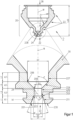
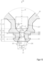
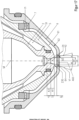
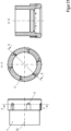
- the nozzle 2 for a plasma arc torch shown in sectional view (top) and sectional detail view (bottom) comprises a body 20 with a total length L20, which extends along a longitudinal axis M, an inner surface 21 and an outer surface 23, a front end 22 and a rear end 28 and a nozzle opening 24 at the front end 22.
- the body 20 has a groove 238 at its front end 22.
- the inner surface 21 of the body 20 of the nozzle 2 has a first section A1 extending from the front end 22 (nozzle opening 24) along the longitudinal axis M, which first tapers conically with an angle ⁇ between its inner surface 211 and the longitudinal axis M, here for example approximately 19°, over a length L1, for example 1.0 mm, and then has a projection in the direction of the longitudinal axis M, which forms an angle ⁇ between its inner surface 213 and the longitudinal axis M, here for example 90°.
- the nozzle opening 24 has a diameter D1 directly at the front end 22, here for example 1.9 mm, and a diameter D2, here for example 1.2 mm, at the end of the conical region of the inner surface 211 of the first section A1. Due to the projection, here for example 0.1 mm, the diameter of the nozzle opening 24 is then reduced to D3, here for example 1.0 mm.
- the second section A3 with the diameter D3 and a length L3, for example 1.0 mm, which has a cylindrical inner surface 220.
- This section is followed by the third section A5, the inner surface 224 of which widens conically with an angle ⁇ between its inner surface 224 and the longitudinal axis M, here for example 45°, from the diameter D3 to the diameter D7, here for example 2.8 mm.
- This section extends along the longitudinal axis M over the length L5, here for example 0.9 mm.
- the fourth section A7 with the diameter D7, which has a cylindrical inner surface 227 with a length L7, for example 1.2 mm. This is followed by another area that widens conically.
- D1 is 1.9 times the diameter D3.
- the diameter D1 is 0.9 mm larger than the diameter D3.
- the area A10 formed by the diameter D1 of the first section A1 directly at the front end 22 of the nozzle opening 24 perpendicular to the longitudinal axis M, which in Figure 12 shown is approximately 2.8 mm 2 , determined according to A 10 3,141 / 4 * D 1 2 .
- the area A30 formed by the smallest diameter D3 of the second section A3 of the nozzle opening 24 perpendicular to the longitudinal axis M, which in Figure 13 shown is approximately 0.8 mm 2 , determined according to A 30 3,141 / 4 * D 3 2 .
- the area A10 is therefore approximately 3.6 times the area A30.
- the quotient of the length L3 and the diameter D3 of the second section A3 is also 1.
- Figure 1 further shows a virtual connecting line V1 which extends between the body edge 201 of the nozzle opening 24 with the diameter D1 at the front end 22 and the body edge 203 at the transition from the first section A1 to the second section A3 of the nozzle opening 24 with the diameter D3.
- the angle ⁇ 1 enclosed by the connecting line V1 and the longitudinal axis M is approximately 24°.
- volume V10 is approximately 1.9 times larger than volume V30.
- Figure 4 shows the detailed view of another embodiment of a nozzle 2 similar to the Figure 1 . It differs from the one in Figure 1 in that the first section A1 has a concavely tapered inner surface 211 from the front end.
- the virtual connecting line V1 which extends between the body edge 201 of the nozzle opening 24 with the diameter D1 at the front end 22 and the body edge 203 at the transition from the first section A1 to the second section A3 of the nozzle opening 24 with the diameter D3, encloses an angle ⁇ 1 of approximately 32° with the longitudinal axis M.
- the area A10 formed by the diameter D1 of the first section A1 directly at the front end 22 of the nozzle opening 24 perpendicular to the longitudinal axis M, which in Figure 12 is approximately 4.5 mm 2 , determined according to A 10 3,141 / 4 * D 1 2 .
- the area A30 formed by the smallest diameter D3 of the second section A3 of the nozzle opening 24 perpendicular to the longitudinal axis M, which in Figure 13 shown is approximately 1.5 mm 2 , determined according to A 30 3,141 / 4 * D 3 2 .
- the area A10 is therefore approximately 2.9 times the area A30.
- the length L1 is, for example, 0.8 mm
- the length L3 is, for example, 1.2 mm
- the length L1 is 0.67 times the length L3.
- volume V10 of the nozzle opening 24 of the first section A1 formed by the inner surface 211 is approximately 2.3 mm 3 .
- the volume V30 of the nozzle opening 24 of the second section A3 formed by the inner surface 220 is approximately 1.8 mm 3 .
- volume V10 is approximately 1.3 times larger than volume V30.
- Figure 5 shows the detailed view of another embodiment of a nozzle 2 similar to the Figure 4 . It differs from the one in Figure 1 in that the first section A1 has a convexly tapered inner surface 211 from the front end.
- the virtual connecting line V1 which extends between the body edge 201 of the nozzle opening 24 with the diameter D1 at the front end 22 and the body edge 203 at the transition from the first section A1 to the second section A3 of the nozzle opening 24 with the diameter D3, encloses an angle ⁇ 1 of approximately 32° with the longitudinal axis M.
- the diameter D1 here is 2.4 mm, for example, and the diameter D3 is 1.4 mm, so the diameter D1 is approximately 1.7 times the diameter D3.
- the length L1 is 0.8 mm, for example, and the length L3 is 1.2 mm, so the length L1 is approximately 0.67 times the length L3.
- the body edge 201 is not clearly recognizable as such, for example because the convex inner surface 211 merges continuously or "flowingly" into the surface 230, then the area of the inner surface(s) is meant by the body edge if, viewed from the rear end 28 of the nozzle 2, an angle ⁇ 2 of 65° is exceeded between a tangent T applied to the inner surface 211 and the longitudinal axis M.
- the virtual connecting line V1 then extends between this area and the body edge 203. This is shown in Figure 5.1 shown.
- Figure 6 shows another embodiment of a nozzle 2 similar to the Figure 4 . It differs from the one in Figure 4 in that the first section A1 has a stepped tapering inner surface 211 from the front end.
- the virtual connecting line V1 which extends between the body edge 201 of the nozzle opening 24 with the diameter D1 at the front end 22 and the body edge 203 at the transition from the first section A1 to the second section A3 of the nozzle opening 24 with the diameter D 3 , encloses an angle ⁇ 1 of approximately 32° with the longitudinal axis M.
- the quotient of the length L3 and the diameter D3 of the second section A3 is approximately 0.86.
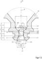
- Figure 7 shows the detailed view of another embodiment of a nozzle 2 similar to the Figure 1 .
- the dimensions are the same as Figure 1 identical.
- Only the second section A3 is designed in such a way that, viewed from the front end 22 of the nozzle 2, its inner surface 220 widens at an angle ⁇ to the longitudinal axis M of, for example, 5°. The widening is conical here.
- the diameter D31 of the section A3 at the transition to the section A5 is therefore larger than the diameter D3 at the transition from the first section A1 to the second section A3 of the nozzle opening 24.
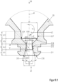
- Figure 7.1 shows the detailed view of another embodiment of a nozzle 2 similar to the Figure 7 .
- the dimensions are the same as Figure 7 identical.
- Only the second section A3 is designed in such a way that its inner surface 220 widens concavely when viewed from the front end 22 of the nozzle 2.
- the diameter D31 of the section A3 at the transition to the section A5 is therefore larger than the diameter D3 at the transition from the first section A1 to the second section A3 of the nozzle opening 24.
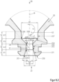
- Figure 7.2 shows the detailed view of another embodiment of a nozzle 2 similar to the Figure 7.1 .
- the dimensions are the same as Figure 7.1 identical.
- Only the second section A3 is designed in such a way that, viewed from the front end 22 of the nozzle 2, its inner surface 220 widens not concavely but convexly.
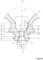
- Figure 8 shows the detailed view of another embodiment of a nozzle 2 similar to the Figure 1
- the second section A3 is designed such that, viewed from the front end 22 of the nozzle 2, its inner surface 220 tapers at an angle ⁇ to the longitudinal axis M of, for example, 175°.
- the taper is conical here.
- the angle ⁇ is 19° and the angle ⁇ 1 is 21°.
- Figure 8.1 shows the detailed view of another embodiment of a nozzle 2 similar to the Figure 8 .
- the second section A3 is designed such that its inner surface 220 tapers convexly when viewed from the front end 22 of the nozzle 2.
- the angle ⁇ in this example is 19° and the angle ⁇ 1 in this example is 21°.
- Figure 8.2 shows the detailed view of another embodiment of a nozzle 2 similar to the Figure 8.1 .
- the second section A3 is designed such that, viewed from the front end 22 of the nozzle 2, its inner surface 220 tapers concavely rather than convexly.
- Figure 9 shows the detailed view of another embodiment of a nozzle 2 similar to the Figure 1 .
- the dimensions are the same as Figure 1 identical.
- the third section A5 has an angle ⁇ of 80° between its inner surface 224 and the longitudinal axis M and widens. However, it is a nozzle whose outer contour differs from the other embodiments. This is for example for use in plasma torches, laser heads or plasma laser heads without liquid cooling for the nozzle. In this example it has no groove 238 for receiving a round ring. A corresponding arrangement is shown in Figure 18 shown.
- Figure 9.1 shows the detailed view of another embodiment of a nozzle 2 similar to the Figure 9 .
- the dimensions are the same as Figure 9 identical.
- Only the third section A5 is designed in such a way that its inner surface 224 widens concavely when viewed from the front end 22 of the nozzle 2.
- the virtual connecting line V4 which extends between the body edge 205 (which in this case can also be referred to as the "inner corner” or “body inner edge”) at the transition from the second section A3 to the third section A5 and the body edge 206 (which in this case can also be referred to as the “inner corner” or “body inner edge”) at the transition from the third section A5 to the fourth section A7, encloses an angle ⁇ 1 of approximately 45° with the longitudinal axis M, for example.
- the area 206 of the inner surface(s) is meant when, viewed from the front end 22 of the nozzle, an angle ⁇ 2 of less than 20° is undercut between a tangent T applied to the inner surface 224 and the longitudinal axis M. This is in Figure 9.3 shown.
- Figure 9.2 shows the detailed view of another embodiment of a nozzle 2 similar to the Figure 9 .
- the dimensions are the same as Figure 9 identical.
- Only the third section A5 is designed in such a way that its inner surface 224 widens convexly when viewed from the front end 22 of the nozzle 2.
- the virtual connecting line V4 which extends between the body edge 205 at the transition from the second section A3 to the third section A5 and the body edge 206 at the transition from the third section A5 to the fourth section A7, encloses an angle ⁇ l of approximately 45° with the longitudinal axis M, for example.
- the body edge 206 is not clearly recognizable as such, because, for example, the concave inner surface 224 merges continuously or "flowingly" into the surface 227, then the area of the inner surface(s) is meant by body edge 206 if, viewed from the front end 22 of the nozzle 2, an angle ⁇ 2 of less than 20° is undercut between a tangent T applied to the inner surface 224 and the longitudinal axis M.
- the virtual connecting line V4 then extends between this area 206 and body edge 205. This is in Figure 9.3 which shows a concavely widening third section A5.
- Figure 10 shows the detailed view of another embodiment of a nozzle 2 similar to the Figure 1 .
- the dimensions are the same as Figure 1 identical.
- the fourth section A7 has, for example, an angle ⁇ of 5° between its inner surface 227 and the longitudinal axis M and widens.
- Figure 11 shows the detailed view of another embodiment of a nozzle 2 similar to the Figure 1 .
- the dimensions are the same as Figure 1 identical.
- the fourth section A7 has, for example, an angle ⁇ of 175° between its inner surface 227 and the longitudinal axis M and tapers.
- Radii can be arranged at the transitions between the respective sections A1, A3, A4, A5 and A7, for example in the size of 0.1 mm.
- Figure 12 , Figure 13 and Figure 13a show the surfaces A10, A20, A30 and A31 of the nozzle opening 24 formed by the diameters D1, D2 and D3 perpendicular to the longitudinal axis M.
- the area A10 is at least 1.7 times larger, advantageously at least 2.1 times larger, than the area A30. Furthermore, it is a maximum of 4 times larger, advantageously a maximum of 3.7 times larger, than the area A30.
- Figure 14 shows the volume V10 enclosed by the inner surfaces 211 and 213 of the nozzle opening 24 of the first section A1 and Figure 15 that through the inner surface 220 enclosed volume V30 of the nozzle opening 24 of the second section A3.
- the volume V10 is larger, advantageously at least 1.3 times larger, and/or a maximum of 2.5 times larger, advantageously a maximum of 2.2 times larger, than the volume V30.
- Figure 16 shows the sectional view of a plasma torch head 1, which can be part of a plasma torch.
- the plasma torch head 1 has a torch body 8, an electrode 3, a nozzle 2 according to the invention, a nozzle cap 5, a nozzle holder 81 which receives the nozzle 2, and a nozzle protection cap 6 which fixes the nozzle 2 in the nozzle holder 81.
- nozzle 2 is shown as an example Figure 1 used.
- the front end 33 of the electrode 3 extends into the interior of the nozzle 2. Furthermore, between the electrode 3 and the nozzle 2 there is a gas guide 4 for the plasma gas or process gas PG.
- the gas guide 4 has openings 41 through which the plasma gas or process gas passes and, for example, leads radially into the interior between the electrode 3 and the nozzle 2.
- the plasma gas or process gas PG can be set in rotation by offsetting it from the radial.
- the gas guide 4 electrically insulates the electrode 3 and nozzle 2 from one another.
- the electrode 3 can be liquid-cooled on the inside, but this is not shown here.
- the cooling medium (WV - flow, WR - return) flows in the space 51 between the nozzle 2 and the nozzle cap 5 and cools it.
- the front end of the nozzle 22 is at least partially covered by the nozzle protection cap 6.
- the nozzle protection cap 6 has an opening 64 which is aligned with the nozzle opening 24 on the longitudinal axis M.
- a gas guide 7 for the secondary gas SG Between the nozzle cap 5, the front end 22 of the nozzle 2 and the nozzle protection cap 6 there is a gas guide 7 for the secondary gas SG.
- the gas guide 7 has openings 71 which guide the secondary gas SG and here, for example, lead radially into the interior 61 between the nozzle cap 5, the front end 22 of the nozzle 2 and the nozzle protection cap 6.
- the plasma gas or process gas PG can be set in rotation by an offset to the radial.
- the gas guide 7 electrically insulates the nozzle cap 5 and the nozzle protection cap 6 from each other.
- the plasma gas or process gas PG is ionized by an arc during plasma cutting and ultimately flows out of the nozzle opening 24 and the opening of the nozzle protection cap 64.
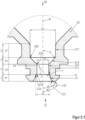
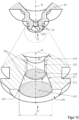
- Figure 17 and Figure 17a is a sectioned detailed view of an arrangement that is part of the plasma torch head from Figure 16 This arrangement can also be part of a laser cutting head or a plasma laser cutting head.
- the arrangement comprises the nozzle 2 and the nozzle protection cap 6.
- the nozzle cap 5 and the gas guide 7 are also shown.
- the front end of the nozzle 2 is at least partially covered by the nozzle protection cap 6.
- the nozzle protection cap 6 has an opening 64 which is aligned with the nozzle opening 24 on the longitudinal axis M.
- a gas guide 7 for secondary gas SG Between the nozzle cap 5, the front end 22 of the nozzle 2 and the nozzle protection cap 6 there is a gas guide 7 for secondary gas SG.
- the gas guide 7 has openings 71 through which the secondary gas SG passes and, for example, leads radially into the interior 61 between the nozzle cap 5, the front end 22 of the nozzle 2 and the nozzle protection cap 6.
- the plasma gas or process gas PG can be set in rotation by offsetting it from the radial.
- the gas guide 7 electrically insulates the nozzle cap 5 and the nozzle protection cap 6 from one another.
- the nozzle protection cap 6 has an opening 64 with a smallest diameter D6 of 3.0 mm.
- the diameter D6 is larger than the diameters D1 and D3.
- the area A60 formed by the diameter D6 perpendicular to the longitudinal axis is larger than the area A10 formed by the diameter D1 and the area A30 formed by the diameter D3.
- the angle ⁇ of the nozzle 2 is 19° in this example and the angle ⁇ 1 of the nozzle 2 is 24° in this example. If the conically tapering inner surfaces 211, seen from the front, are virtually extended in the direction of the front end 22 of the nozzle, i.e. out of the nozzle 2, this forms the virtual line V2. This does not touch the body edge 65 of the nozzle protection cap 6 formed by the opening 64 with the diameter D6. The same applies to the extended virtual connecting line V1 between the body edge 201 of the nozzle opening 24 at the front end 22 and the body edge 203 at the transition from the first section A1 to the second section A3.
- the area A60 and the diameter D6 of the opening 64 of the nozzle protection cap 6 are larger than the virtual areas A70 and A80 or diameter of the nozzle 2 projected onto the nozzle protection cap 6 by the extended virtual connecting lines V1 and V2.
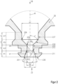
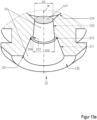
- FIG 18 and Figure 18a A detailed sectioned view of an arrangement is shown.
- the claimed arrangement comprises the nozzle 2 from Figure 9 and a nozzle protection cap 6.
- a gas guide 7 is also shown.
- This arrangement can be part of a plasma torch head, a laser cutting head or a plasma laser cutting head.
- the nozzle 2 is not enclosed by a nozzle cap.
- the nozzle protection cap 6 has an opening 64 with a smallest diameter D6 of 3.0 mm.
- the diameter D6 is larger than the diameters D1 and D3 of the nozzle 2.
- the area A60 formed by the diameter D6 perpendicular to the longitudinal axis is larger than the area A10 formed by the diameter D1 and the area A30 formed by the diameter D3.
- the front end of the nozzle 22 is at least partially covered by the nozzle protection cap 6.
- the nozzle protection cap 6 has an opening 64 which is aligned with the nozzle opening 24 on the longitudinal axis M.
- the gas guide 7 has openings 71 through which the secondary gas SG is guided and, for example, leads radially into the interior 61 between the nozzle 2 and the nozzle protection cap 6.
- the plasma gas PG can be set in rotation by offsetting it from the radial (see Figure 21 ).
- the gas guide 7 electrically insulates the nozzle 2 and the nozzle protection cap 6 from each other.
- the angle ⁇ of the nozzle 2 is 19° in this example and the angle ⁇ 1 of the nozzle 2 is 24° in this example. If the conically tapering inner surface seen from the front is virtually extended in the direction of the front end 22 of the nozzle 2, i.e. out of the nozzle 2, this forms the virtual line V2. This does not touch the body edges 65 of the nozzle protection cap 6 formed by the opening 64 with the diameter D6. The same applies to the extended virtual connecting line V1 between the body edge 201 of the nozzle opening 24 at the front end 22 and the body edge 203 at the transition from the first section A1 to the second section A3.
- the area A60 and the diameter D6 of the opening 64 of the nozzle protection cap 6 are larger than the virtual areas A70 and A80 or diameter of the nozzle 2 projected onto the nozzle protection cap 6 by the extended virtual connecting lines V1 and V2.
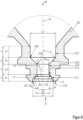
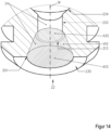
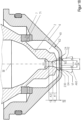
- Figure 19 is a sectional detail view of an assembly that is part of the plasma torch head of Figure 16
- the arrangement comprises a nozzle 2 according to a particular embodiment of the invention and an electrode 3.
- a gas guide 4 is shown.
- the front end 33 of the electrode 3 projects into the interior of the nozzle 2.
- the gas guide 4 for the plasma gas PG between the electrode 3 and the nozzle 2.
- the gas guide 4 has openings 41 through which the plasma gas passes and, for example, leads radially into the interior space between the electrode 3 and the nozzle 2.
- the plasma gas PG can be set in rotation by an offset from the radial.
- the gas guide 4 electrically insulates the electrode 3 and nozzle 2 from one another.
- the distance L13 between the front end 33 of the electrode 3 and the transition from the third section A5 to the second section A3 of the nozzle opening 24 of the nozzle 2 is 6 mm long, the length L1 of the first section A1 and the length L3 of the second section A3 are each 1 mm.
- the sum of the lengths L1 and L3 is then 2 mm.
- L1, L2 and the sum of both are shorter than the length of the distance L13.
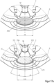
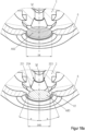
- the gas guide 7 for the secondary gas SG is shown as an example.
- the middle sectioned illustration shows that the openings 71 are arranged offset from the radial to the longitudinal axis M.
- the gas flowing through the openings 71 is thus set in rotation.
- the rotation can also be achieved by a different spatial orientation of the openings, for example an inclination to the longitudinal axis M.
- the gas guide 4 for the plasma gas or process gas is shown as an example.
- the middle sectioned illustration shows that the openings 41 are arranged offset from the radial to the longitudinal axis M.
- the gas flowing through the openings 41 is thus set in rotation.
- the rotation can also be achieved by a different spatial orientation of the openings, for example an inclination to the longitudinal axis M.
- the above description refers to a nozzle for plasma cutting or for a plasma torch head.
- the plasma torch head can be a plasma torch cutting head.
- the description should also apply in an analogous manner to a nozzle for laser cutting or for a laser cutting head and for plasma laser cutting or for a plasma laser cutting head.
Landscapes
- Engineering & Computer Science (AREA)
- Physics & Mathematics (AREA)
- Plasma & Fusion (AREA)
- Spectroscopy & Molecular Physics (AREA)
- Mechanical Engineering (AREA)
- Optics & Photonics (AREA)
- Geometry (AREA)
- Plasma Technology (AREA)
- Arc Welding In General (AREA)
- Laser Beam Processing (AREA)
Applications Claiming Priority (3)
| Application Number | Priority Date | Filing Date | Title |
|---|---|---|---|
| DE102017122015 | 2017-09-22 | ||
| DE102018100917.8A DE102018100917A1 (de) | 2017-09-22 | 2018-01-17 | Düse für einen Plasmabrennerkopf, Laserschneidkopf und Plasma-Laser-Schneidkopf, Anordnungen, Plasmabrennerkopf und Plasmabrenner mit selbiger/selbigen, Laserschneidkopf mit selbiger/selbigen und Plasma-Laser-Schneidkopf mit selbiger/selbigen |
| PCT/DE2018/100789 WO2019057244A1 (de) | 2017-09-22 | 2018-09-14 | Düse für einen plasmabrennerkopf, laserschneidkopf und plasma-laser-schneidkopf, anordnungen, plasmabrennerkopf und plasmabrenner mit selbiger/selbigen, laserschneidkopf mit selbiger/selbigen und plasma-laser-schneidkopf mit selbiger/selbigen |
Publications (3)
| Publication Number | Publication Date |
|---|---|
| EP3684544A1 EP3684544A1 (de) | 2020-07-29 |
| EP3684544C0 EP3684544C0 (de) | 2024-10-30 |
| EP3684544B1 true EP3684544B1 (de) | 2024-10-30 |
Family
ID=65638272
Family Applications (1)
| Application Number | Title | Priority Date | Filing Date |
|---|---|---|---|
| EP18792367.7A Active EP3684544B1 (de) | 2017-09-22 | 2018-09-14 | Düse für einen plasmabrennerkopf, laserschneidkopf und plasma-laser-schneidkopf |
Country Status (10)
| Country | Link |
|---|---|
| US (1) | US11856684B2 (cg-RX-API-DMAC7.html) |
| EP (1) | EP3684544B1 (cg-RX-API-DMAC7.html) |
| JP (1) | JP7281456B2 (cg-RX-API-DMAC7.html) |
| KR (1) | KR20200058454A (cg-RX-API-DMAC7.html) |
| CN (1) | CN111565878B (cg-RX-API-DMAC7.html) |
| CA (1) | CA3076453A1 (cg-RX-API-DMAC7.html) |
| DE (1) | DE102018100917A1 (cg-RX-API-DMAC7.html) |
| ES (1) | ES2997336T3 (cg-RX-API-DMAC7.html) |
| PL (1) | PL3684544T3 (cg-RX-API-DMAC7.html) |
| WO (1) | WO2019057244A1 (cg-RX-API-DMAC7.html) |
Families Citing this family (7)
| Publication number | Priority date | Publication date | Assignee | Title |
|---|---|---|---|---|
| DE102019210524B4 (de) * | 2019-07-17 | 2024-09-19 | Volkswagen Aktiengesellschaft | Elektrodenanordnung für einen Plasmabrenner |
| US20220346216A1 (en) * | 2019-09-12 | 2022-10-27 | Kjellberg-Stiftung | Wear Part for an Arc Torch and Plasma Torch, Arc Torch and Plasma Torch Comprising Same, Method for Plasma Cutting and Method for Producing an Electrode for an Arc Torch and Plasma Torch |
| US20210316396A1 (en) * | 2019-10-03 | 2021-10-14 | American Torch Tip Company | Laser Cutting Nozzle with Non-Rotatable Shroud |
| IT202000008386A1 (it) * | 2020-04-20 | 2021-10-20 | Prima Ind Spa | Terminale operativo laser, macchina operatrice laser e procedimento di fabbricazione corrispondenti |
| US12103105B2 (en) * | 2021-01-28 | 2024-10-01 | Ii-Vi Delaware, Inc. | Nozzle adapter for laser cutting head |
| CN115338522A (zh) * | 2022-08-31 | 2022-11-15 | 西安聚能医工科技有限公司 | 一种等离子炬用喷嘴 |
| WO2025144999A1 (en) * | 2023-12-29 | 2025-07-03 | The Esab Group, Inc. | Consumables for processing torches |
Family Cites Families (29)
| Publication number | Priority date | Publication date | Assignee | Title |
|---|---|---|---|---|
| FR2190561B1 (cg-RX-API-DMAC7.html) * | 1972-07-03 | 1974-10-25 | Soudure Autogene Francaise | |
| GB1500979A (en) * | 1976-06-16 | 1978-02-15 | Rolls Royce | Jet propulsion nozzles |
| US4300723A (en) * | 1980-02-29 | 1981-11-17 | The United States Of America As Represented By The Administrator Of The National Aeronautics And Space Administration | Controlled overspray spray nozzle |
| US5695662A (en) | 1988-06-07 | 1997-12-09 | Hypertherm, Inc. | Plasma arc cutting process and apparatus using an oxygen-rich gas shield |
| US4866240A (en) * | 1988-09-08 | 1989-09-12 | Stoody Deloro Stellite, Inc. | Nozzle for plasma torch and method for introducing powder into the plasma plume of a plasma torch |
| JP2516804B2 (ja) * | 1988-12-26 | 1996-07-24 | 株式会社小松製作所 | プラズマト−チ |
| SE463223B (sv) * | 1989-02-17 | 1990-10-22 | Svenska Rotor Maskiner Ab | Skruvrotormaskin med ljuddaempare |
| JP3010879B2 (ja) * | 1992-02-25 | 2000-02-21 | 松下電器産業株式会社 | プラズマトーチ |
| JPH07185823A (ja) * | 1992-11-27 | 1995-07-25 | Komatsu Ltd | プラズマトーチ |
| JP3531682B2 (ja) * | 1994-02-28 | 2004-05-31 | 石川島播磨重工業株式会社 | プラズマトーチノズル |
| US5573682A (en) * | 1995-04-20 | 1996-11-12 | Plasma Processes | Plasma spray nozzle with low overspray and collimated flow |
| US5660743A (en) * | 1995-06-05 | 1997-08-26 | The Esab Group, Inc. | Plasma arc torch having water injection nozzle assembly |
| FR2735710B1 (fr) * | 1995-06-23 | 1997-07-25 | Soudure Autogene Francaise | Tete de torche a plasma et torche a plasma la comportant |
| US5841095A (en) * | 1996-10-28 | 1998-11-24 | Hypertherm, Inc. | Apparatus and method for improved assembly concentricity in a plasma arc torch |
| CH693083A5 (de) * | 1998-12-21 | 2003-02-14 | Sulzer Metco Ag | Düse sowie Düsenanordnung für einen Brennerkopf eines Plasmaspritzgeräts. |
| DE10319481A1 (de) * | 2003-04-30 | 2004-11-18 | Linde Ag | Lavaldüse für das thermische Spritzen und das kinetische Spritzen |
| US7375302B2 (en) * | 2004-11-16 | 2008-05-20 | Hypertherm, Inc. | Plasma arc torch having an electrode with internal passages |
| CN101204123B (zh) * | 2005-04-19 | 2011-10-05 | 海别得公司 | 提供斜角屏蔽流喷射的等离子体弧气炬 |
| DE102007005316B4 (de) * | 2006-08-16 | 2009-12-03 | Kjellberg Finsterwalde Plasma Und Maschinen Gmbh | Verbindung zwischen einem Plasmabrennerverschleißteil und einer Plasmabrennerverschleißteilhalterung, Plasmabrennerverschleißteil und Plasmabrennerverschleißteilhalterung |
| DE102008056278A1 (de) * | 2008-10-25 | 2010-04-29 | Kjellberg Finsterwalde Plasma Und Maschinen Gmbh | System zur thermischen Bearbeitung von Werkstücken |
| CN201371088Y (zh) * | 2008-11-13 | 2009-12-30 | 关星 | 狭缝式喷嘴 |
| EP2449862B1 (de) * | 2009-07-03 | 2015-09-02 | Kjellberg Finsterwalde Plasma und Maschinen GmbH | Düse für einen flüssigkeitsgekühlten plasmabrenner sowie plasmabrennerkopf mit derselben |
| EP2477779A1 (en) * | 2009-09-14 | 2012-07-25 | The Esab Group, Inc. | Method of underwater marking on a workpiece with a plasma arc torch |
| US8546719B2 (en) * | 2010-12-13 | 2013-10-01 | The Esab Group, Inc. | Method and plasma arc torch system for marking and cutting workpieces with the same set of consumables |
| WO2012115533A1 (en) * | 2011-02-25 | 2012-08-30 | Nippon Steel Corporation, | Plasma torch |
| US9560733B2 (en) * | 2014-02-24 | 2017-01-31 | Lincoln Global, Inc. | Nozzle throat for thermal processing and torch equipment |
| EP2942144B1 (de) * | 2014-05-07 | 2024-07-03 | Kjellberg-Stiftung | Plasmaschneidbrenneranordnung sowie die Verwendung von Verschleißteilen bei einer Plasmaschneidbrenneranordnung |
| US10129970B2 (en) * | 2014-07-30 | 2018-11-13 | American Torch Tip, Co. | Smooth radius nozzle for use in a plasma cutting device |
| WO2016138524A1 (en) * | 2015-02-27 | 2016-09-01 | Hypertherm, Inc. | Automatically sensing consumable components in thermal processing systems |
-
2018
- 2018-01-17 DE DE102018100917.8A patent/DE102018100917A1/de active Pending
- 2018-09-14 US US16/649,927 patent/US11856684B2/en active Active
- 2018-09-14 KR KR1020207010851A patent/KR20200058454A/ko not_active Ceased
- 2018-09-14 ES ES18792367T patent/ES2997336T3/es active Active
- 2018-09-14 EP EP18792367.7A patent/EP3684544B1/de active Active
- 2018-09-14 JP JP2020516590A patent/JP7281456B2/ja active Active
- 2018-09-14 PL PL18792367.7T patent/PL3684544T3/pl unknown
- 2018-09-14 CN CN201880074623.XA patent/CN111565878B/zh active Active
- 2018-09-14 CA CA3076453A patent/CA3076453A1/en active Pending
- 2018-09-14 WO PCT/DE2018/100789 patent/WO2019057244A1/de not_active Ceased
Also Published As
| Publication number | Publication date |
|---|---|
| CN111565878B (zh) | 2023-04-21 |
| CN111565878A (zh) | 2020-08-21 |
| EP3684544C0 (de) | 2024-10-30 |
| US20200314993A1 (en) | 2020-10-01 |
| DE102018100917A1 (de) | 2019-03-28 |
| WO2019057244A1 (de) | 2019-03-28 |
| RU2020112273A (ru) | 2021-09-27 |
| JP7281456B2 (ja) | 2023-05-25 |
| KR20200058454A (ko) | 2020-05-27 |
| PL3684544T3 (pl) | 2025-03-17 |
| CA3076453A1 (en) | 2019-03-28 |
| ES2997336T3 (en) | 2025-02-17 |
| RU2020112273A3 (cg-RX-API-DMAC7.html) | 2021-11-19 |
| US11856684B2 (en) | 2023-12-26 |
| EP3684544A1 (de) | 2020-07-29 |
| JP2020534162A (ja) | 2020-11-26 |
Similar Documents
| Publication | Publication Date | Title |
|---|---|---|
| EP3684544B1 (de) | Düse für einen plasmabrennerkopf, laserschneidkopf und plasma-laser-schneidkopf | |
| DE69222605T2 (de) | Plasmalichtbogenbrenner mit verbessertem Düsenaufbau | |
| EP2804450B1 (de) | Mehrteiliges Isolierteil für einen Lichtbogenplasmabrenner, Brenner und zugehörige Anordnungen mit demselben und zugehörigen Verfahren | |
| EP2465334B1 (de) | Düsenschutzkappe und düsenschutzkappenhalter sowie lichtbogenplasmabrenner mit derselben und/oder demselben | |
| DE102011088433A1 (de) | Verfahren und Plasmalichtbogenbrennersystem zum Markieren und Schneiden von Werkstücken mit dem selben Satz an Hilfsstoffen | |
| DE102008062731B4 (de) | Elektrode für einen Plasmabrenner | |
| DE102019100581A1 (de) | Gasdüse zum Ausströmen eines Schutzgasstromes und Brennerhals mit einer Gasdüse | |
| EP2855071B1 (de) | BRENNER FÜR DAS WOLFRAM-INERTGAS-SCHWEIßEN | |
| DE3426410A1 (de) | Schweissbrenner zum plasma-mig-schweissen | |
| EP2457681B1 (de) | Brenner für das Wolfram-Inertgas-Schweißen sowie Elektrode zur Verwendung bei einem solchen Brenner | |
| EP2667689A1 (de) | Elektrode für Plasmaschneidbrenner sowie deren Verwendung | |
| DE3834224C2 (de) | Lichtbogen-Schutzgasschweißbrenner zum Schweißen an schwer zugänglichen Stellen | |
| EP3829807B1 (de) | Verbindungsteile für einen bearbeitungskopf zur thermischen materialbearbeitung, insbesondere für einen plasmabrennerkopf | |
| DE69300563T2 (de) | Lichtbogenplasmabrenner mit konische Bohrung enthaltender Elektrode. | |
| EP4193811B1 (de) | Elektrode für einen plasmaschneidbrenner, plasmaschneidbrenner und verfahren mit derselben | |
| EP4029356A2 (de) | VERSCHLEIßTEIL FÜR EINEN LICHTBOGENBRENNER UND PLASMABRENNER SOWIE LICHTBOGENBRENNER UND PLASMABRENNER MIT DEMSELBEN UND VERFAHREN ZUM PLASMASCHNEIDEN SOWIE VERFAHREN ZUR HERSTELLUNG EINER ELEKTRODE FÜR EINEN LICHTBOGENBRENNER UND PLASMABRENNER | |
| DE10144516B4 (de) | Plasmabrenner | |
| EP3663029B1 (de) | Elektrodeneinheit für inertgasschweissen mit nicht abschmelzender elektrode | |
| EP4595709A1 (de) | Bestandteil, wie z. b. verschleissteil, für einen lichtbogenbrenner, insbesondere einen plasmabrenner oder plasmaschneidbrenner, lichtbogenbrenner mit demselben sowie verfahren zum plasmaschneiden | |
| EP3953095A1 (de) | Verfahren zum plasmaschneiden | |
| EP4082708B1 (de) | Schweissbrenner mit gaskühlung | |
| DE2236487C3 (de) | Wirbelstabilisierter Lichtbogen-Plasmagenerator | |
| EP4363149A1 (de) | Verfahren zum plasmaschneiden von werkstücken | |
| DE1003880B (de) | Schweissbrenner zum Lichtbogen-Schutzgas-Schweissen mit keramischer Gasduese | |
| DE2236487B2 (de) | Wirbelstabilisierter lichtbogen- plasmagenerator |
Legal Events
| Date | Code | Title | Description |
|---|---|---|---|
| STAA | Information on the status of an ep patent application or granted ep patent |
Free format text: STATUS: UNKNOWN |
|
| STAA | Information on the status of an ep patent application or granted ep patent |
Free format text: STATUS: THE INTERNATIONAL PUBLICATION HAS BEEN MADE |
|
| PUAI | Public reference made under article 153(3) epc to a published international application that has entered the european phase |
Free format text: ORIGINAL CODE: 0009012 |
|
| STAA | Information on the status of an ep patent application or granted ep patent |
Free format text: STATUS: REQUEST FOR EXAMINATION WAS MADE |
|
| 17P | Request for examination filed |
Effective date: 20200320 |
|
| AK | Designated contracting states |
Kind code of ref document: A1 Designated state(s): AL AT BE BG CH CY CZ DE DK EE ES FI FR GB GR HR HU IE IS IT LI LT LU LV MC MK MT NL NO PL PT RO RS SE SI SK SM TR |
|
| AX | Request for extension of the european patent |
Extension state: BA ME |
|
| DAV | Request for validation of the european patent (deleted) | ||
| DAX | Request for extension of the european patent (deleted) | ||
| RAP3 | Party data changed (applicant data changed or rights of an application transferred) |
Owner name: KJELLBERG-STIFTUNG |
|
| STAA | Information on the status of an ep patent application or granted ep patent |
Free format text: STATUS: EXAMINATION IS IN PROGRESS |
|
| 17Q | First examination report despatched |
Effective date: 20230417 |
|
| P01 | Opt-out of the competence of the unified patent court (upc) registered |
Effective date: 20230411 |
|
| REG | Reference to a national code |
Ref country code: DE Ref country code: DE Ref legal event code: R079 Ref document number: 502018015280 Country of ref document: DE Free format text: PREVIOUS MAIN CLASS: B23K0010020000 Ipc: B23K0010000000 |
|
| GRAP | Despatch of communication of intention to grant a patent |
Free format text: ORIGINAL CODE: EPIDOSNIGR1 |
|
| STAA | Information on the status of an ep patent application or granted ep patent |
Free format text: STATUS: GRANT OF PATENT IS INTENDED |
|
| RIC1 | Information provided on ipc code assigned before grant |
Ipc: B23K 10/02 20060101ALI20240112BHEP Ipc: B23K 26/14 20140101ALI20240112BHEP Ipc: B23K 26/38 20140101ALI20240112BHEP Ipc: B23K 10/00 20060101AFI20240112BHEP |
|
| INTG | Intention to grant announced |
Effective date: 20240130 |
|
| GRAJ | Information related to disapproval of communication of intention to grant by the applicant or resumption of examination proceedings by the epo deleted |
Free format text: ORIGINAL CODE: EPIDOSDIGR1 |
|
| STAA | Information on the status of an ep patent application or granted ep patent |
Free format text: STATUS: EXAMINATION IS IN PROGRESS |
|
| INTC | Intention to grant announced (deleted) | ||
| GRAP | Despatch of communication of intention to grant a patent |
Free format text: ORIGINAL CODE: EPIDOSNIGR1 |
|
| STAA | Information on the status of an ep patent application or granted ep patent |
Free format text: STATUS: GRANT OF PATENT IS INTENDED |
|
| GRAS | Grant fee paid |
Free format text: ORIGINAL CODE: EPIDOSNIGR3 |
|
| INTG | Intention to grant announced |
Effective date: 20240724 |
|
| GRAA | (expected) grant |
Free format text: ORIGINAL CODE: 0009210 |
|
| STAA | Information on the status of an ep patent application or granted ep patent |
Free format text: STATUS: THE PATENT HAS BEEN GRANTED |
|
| AK | Designated contracting states |
Kind code of ref document: B1 Designated state(s): AL AT BE BG CH CY CZ DE DK EE ES FI FR GB GR HR HU IE IS IT LI LT LU LV MC MK MT NL NO PL PT RO RS SE SI SK SM TR |
|
| REG | Reference to a national code |
Ref country code: GB Ref legal event code: FG4D Free format text: NOT ENGLISH |
|
| REG | Reference to a national code |
Ref country code: CH Ref legal event code: EP |
|
| P04 | Withdrawal of opt-out of the competence of the unified patent court (upc) registered |
Free format text: CASE NUMBER: APP_56387/2024 Effective date: 20241016 |
|
| REG | Reference to a national code |
Ref country code: IE Ref legal event code: FG4D Free format text: LANGUAGE OF EP DOCUMENT: GERMAN |
|
| REG | Reference to a national code |
Ref country code: DE Ref legal event code: R096 Ref document number: 502018015280 Country of ref document: DE |
|
| U01 | Request for unitary effect filed |
Effective date: 20241107 |
|
| U07 | Unitary effect registered |
Designated state(s): AT BE BG DE DK EE FI FR IT LT LU LV MT NL PT RO SE SI Effective date: 20241115 |
|
| REG | Reference to a national code |
Ref country code: SK Ref legal event code: T3 Ref document number: E 45587 Country of ref document: SK |
|
| REG | Reference to a national code |
Ref country code: ES Ref legal event code: FG2A Ref document number: 2997336 Country of ref document: ES Kind code of ref document: T3 Effective date: 20250217 |
|
| PG25 | Lapsed in a contracting state [announced via postgrant information from national office to epo] |
Ref country code: IS Free format text: LAPSE BECAUSE OF FAILURE TO SUBMIT A TRANSLATION OF THE DESCRIPTION OR TO PAY THE FEE WITHIN THE PRESCRIBED TIME-LIMIT Effective date: 20250228 Ref country code: HR Free format text: LAPSE BECAUSE OF FAILURE TO SUBMIT A TRANSLATION OF THE DESCRIPTION OR TO PAY THE FEE WITHIN THE PRESCRIBED TIME-LIMIT Effective date: 20241030 |
|
| PG25 | Lapsed in a contracting state [announced via postgrant information from national office to epo] |
Ref country code: NO Free format text: LAPSE BECAUSE OF FAILURE TO SUBMIT A TRANSLATION OF THE DESCRIPTION OR TO PAY THE FEE WITHIN THE PRESCRIBED TIME-LIMIT Effective date: 20250130 |
|
| PG25 | Lapsed in a contracting state [announced via postgrant information from national office to epo] |
Ref country code: GR Free format text: LAPSE BECAUSE OF FAILURE TO SUBMIT A TRANSLATION OF THE DESCRIPTION OR TO PAY THE FEE WITHIN THE PRESCRIBED TIME-LIMIT Effective date: 20250131 |
|
| PG25 | Lapsed in a contracting state [announced via postgrant information from national office to epo] |
Ref country code: RS Free format text: LAPSE BECAUSE OF FAILURE TO SUBMIT A TRANSLATION OF THE DESCRIPTION OR TO PAY THE FEE WITHIN THE PRESCRIBED TIME-LIMIT Effective date: 20250130 |
|
| PG25 | Lapsed in a contracting state [announced via postgrant information from national office to epo] |
Ref country code: SM Free format text: LAPSE BECAUSE OF FAILURE TO SUBMIT A TRANSLATION OF THE DESCRIPTION OR TO PAY THE FEE WITHIN THE PRESCRIBED TIME-LIMIT Effective date: 20241030 |
|
| PLBE | No opposition filed within time limit |
Free format text: ORIGINAL CODE: 0009261 |
|
| STAA | Information on the status of an ep patent application or granted ep patent |
Free format text: STATUS: NO OPPOSITION FILED WITHIN TIME LIMIT |
|
| 26N | No opposition filed |
Effective date: 20250731 |
|
| PGFP | Annual fee paid to national office [announced via postgrant information from national office to epo] |
Ref country code: PL Payment date: 20250819 Year of fee payment: 8 |
|
| PGFP | Annual fee paid to national office [announced via postgrant information from national office to epo] |
Ref country code: CZ Payment date: 20250828 Year of fee payment: 8 |
|
| PGFP | Annual fee paid to national office [announced via postgrant information from national office to epo] |
Ref country code: SK Payment date: 20250826 Year of fee payment: 8 |
|
| U20 | Renewal fee for the european patent with unitary effect paid |
Year of fee payment: 8 Effective date: 20250925 |