EP3684285B1 - Chirurgischer instrumententisch mit sterilisationsfunktion - Google Patents
Chirurgischer instrumententisch mit sterilisationsfunktion Download PDFInfo
- Publication number
- EP3684285B1 EP3684285B1 EP18859558.1A EP18859558A EP3684285B1 EP 3684285 B1 EP3684285 B1 EP 3684285B1 EP 18859558 A EP18859558 A EP 18859558A EP 3684285 B1 EP3684285 B1 EP 3684285B1
- Authority
- EP
- European Patent Office
- Prior art keywords
- panel
- sheet
- power port
- mobile platform
- substrate
- Prior art date
- Legal status (The legal status is an assumption and is not a legal conclusion. Google has not performed a legal analysis and makes no representation as to the accuracy of the status listed.)
- Active
Links
Images


Classifications
-
- A—HUMAN NECESSITIES
- A61—MEDICAL OR VETERINARY SCIENCE; HYGIENE
- A61L—METHODS OR APPARATUS FOR STERILISING MATERIALS OR OBJECTS IN GENERAL; DISINFECTION, STERILISATION OR DEODORISATION OF AIR; CHEMICAL ASPECTS OF BANDAGES, DRESSINGS, ABSORBENT PADS OR SURGICAL ARTICLES; MATERIALS FOR BANDAGES, DRESSINGS, ABSORBENT PADS OR SURGICAL ARTICLES
- A61L2/00—Disinfection or sterilisation of materials or objects, in general; Accessories therefor
- A61L2/02—Disinfection or sterilisation of materials or objects, in general; Accessories therefor using physical processes
- A61L2/08—Radiation
- A61L2/10—Ultraviolet [UV] radiation
-
- A—HUMAN NECESSITIES
- A61—MEDICAL OR VETERINARY SCIENCE; HYGIENE
- A61B—DIAGNOSIS; SURGERY; IDENTIFICATION
- A61B50/00—Containers, covers, furniture or holders specially adapted for surgical or diagnostic appliances or instruments, e.g. sterile covers
- A61B50/10—Furniture specially adapted for surgical or diagnostic appliances or instruments
- A61B50/13—Trolleys, e.g. carts
-
- A—HUMAN NECESSITIES
- A61—MEDICAL OR VETERINARY SCIENCE; HYGIENE
- A61B—DIAGNOSIS; SURGERY; IDENTIFICATION
- A61B50/00—Containers, covers, furniture or holders specially adapted for surgical or diagnostic appliances or instruments, e.g. sterile covers
- A61B50/10—Furniture specially adapted for surgical or diagnostic appliances or instruments
- A61B50/15—Mayo stands; Tables
-
- A—HUMAN NECESSITIES
- A61—MEDICAL OR VETERINARY SCIENCE; HYGIENE
- A61B—DIAGNOSIS; SURGERY; IDENTIFICATION
- A61B50/00—Containers, covers, furniture or holders specially adapted for surgical or diagnostic appliances or instruments, e.g. sterile covers
- A61B50/20—Holders specially adapted for surgical or diagnostic appliances or instruments
- A61B50/24—Stands
-
- A—HUMAN NECESSITIES
- A61—MEDICAL OR VETERINARY SCIENCE; HYGIENE
- A61L—METHODS OR APPARATUS FOR STERILISING MATERIALS OR OBJECTS IN GENERAL; DISINFECTION, STERILISATION OR DEODORISATION OF AIR; CHEMICAL ASPECTS OF BANDAGES, DRESSINGS, ABSORBENT PADS OR SURGICAL ARTICLES; MATERIALS FOR BANDAGES, DRESSINGS, ABSORBENT PADS OR SURGICAL ARTICLES
- A61L2/00—Disinfection or sterilisation of materials or objects, in general; Accessories therefor
- A61L2/26—Accessories
-
- A—HUMAN NECESSITIES
- A61—MEDICAL OR VETERINARY SCIENCE; HYGIENE
- A61L—METHODS OR APPARATUS FOR STERILISING MATERIALS OR OBJECTS IN GENERAL; DISINFECTION, STERILISATION OR DEODORISATION OF AIR; CHEMICAL ASPECTS OF BANDAGES, DRESSINGS, ABSORBENT PADS OR SURGICAL ARTICLES; MATERIALS FOR BANDAGES, DRESSINGS, ABSORBENT PADS OR SURGICAL ARTICLES
- A61L2103/00—Materials or objects being the target of disinfection or sterilisation
- A61L2103/15—Laboratory, medical or dentistry appliances, e.g. catheters or sharps
-
- A—HUMAN NECESSITIES
- A61—MEDICAL OR VETERINARY SCIENCE; HYGIENE
- A61L—METHODS OR APPARATUS FOR STERILISING MATERIALS OR OBJECTS IN GENERAL; DISINFECTION, STERILISATION OR DEODORISATION OF AIR; CHEMICAL ASPECTS OF BANDAGES, DRESSINGS, ABSORBENT PADS OR SURGICAL ARTICLES; MATERIALS FOR BANDAGES, DRESSINGS, ABSORBENT PADS OR SURGICAL ARTICLES
- A61L2202/00—Aspects relating to methods or apparatus for disinfecting or sterilising materials or objects
- A61L2202/10—Apparatus features
- A61L2202/14—Means for controlling sterilisation processes, data processing, presentation and storage means, e.g. sensors, controllers, programs
-
- A—HUMAN NECESSITIES
- A61—MEDICAL OR VETERINARY SCIENCE; HYGIENE
- A61L—METHODS OR APPARATUS FOR STERILISING MATERIALS OR OBJECTS IN GENERAL; DISINFECTION, STERILISATION OR DEODORISATION OF AIR; CHEMICAL ASPECTS OF BANDAGES, DRESSINGS, ABSORBENT PADS OR SURGICAL ARTICLES; MATERIALS FOR BANDAGES, DRESSINGS, ABSORBENT PADS OR SURGICAL ARTICLES
- A61L2202/00—Aspects relating to methods or apparatus for disinfecting or sterilising materials or objects
- A61L2202/10—Apparatus features
- A61L2202/16—Mobile applications, e.g. portable devices, trailers, devices mounted on vehicles
Definitions
- the present invention is related to tables and surfaces that support and protect instruments used during surgical procedures.
- Typical instrument tables found in medical operating rooms are fitted with sterile covers, and used as a staging area for medical instruments used in surgeries. Surgical infections are nonetheless still a serious problem. Bacteria migrate using air currents (e.g., Brownian motion or microcurrents due to motion in the room) and dust. Thus, air movement, noise level, and length of the operation all influence the likelihood of infections due to surgery. A need exists to reduce the pro-infection effects of correlation of air movement and other factors on infection rates.
- EP1905343 discloses a medical instrument storage system for storing and carrying a medical instrument, which is structured to allow easy power supply required for keeping the stored instrument in good sanitary condition and easy sanitary control and information management of the stored medical instrument through the power supply.
- US 2009/045154 discloses a rack for use in an operating room during surgery to hold surgical instruments.
- the rack includes a vertical support (including an adjustable height portion); rack support braces; rack support arms; a base interface member; casters; a base; and lighted trays.
- the lighted trays radiate ultraviolet and/or visible light to provide visible light in low light conditions and/or to inhibit bacterial growth.
- Claims 1 and 7 define the invention and the dependent claims disclose embodiments. No surgical methods are claimed per se.
- An uncovered ultraviolet light emitting panel is disclosed for use in supporting instruments in an operating room. The panel fits inside an autoclave for sterilization and therefore can be utilized without a sterile cover. In use, the panel irradiates surgical instruments and the nearby air continuously.
- an apparatus may comprise a first plurality of ultraviolet light emitting diodes positioned on a first substrate; a first sheet of transparent material in thermal contact with the first plurality of ultraviolet light emitting diodes; a first frame surrounding the first substrate and the first sheet, forming a first panel; and a mobile platform to support the first panel over a floor, the mobile platform adapted to receive the first panel in a configuration such that light emitted from the first plurality of ultraviolet light emitting diodes is directed in an upward direction from the floor.
- an assembly method may comprise positioning a first plurality of ultraviolet light emitting diodes on a first substrate; fixing a first sheet of transparent material in thermal contact with the first plurality of ultraviolet light emitting diodes; forming a first frame surrounding the first substrate and the first sheet, forming a first panel; and assembling a mobile platform to support the first panel over a floor, the mobile platform adapted to receive the first panel in a configuration such that light emitted from the first plurality of ultraviolet light emitting diodes is directed in an upward direction from the floor.
- LED herein refers to a light emitting diode which may comprise a semiconductor diode that glows when a voltage is applied.
- UV herein refers to ultraviolet light, e.g., electromagnetic radiation having a wavelength shorter than that of the violet end of the visible spectrum but longer than that of X-rays and/or equipment or techniques using or concerned with such radiation.
- UV LED and/or “ultraviolet LED” herein refer to an ultraviolet light emitting diode, i.e., a light emitting diode capable of transmitting and/or producing ultraviolet light.
- Release mechanism herein refers to a latch, friction coupling, threaded device, etc. which can be operated by hand without tools to quickly (e.g., within 2-10 seconds) disengage a UV panel from the underlying bracket or table top supporting it.
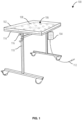
- FIG. 1 illustrates a sterilizing instrument table 100 in accordance with one embodiment.
- the sterilizing instrument table 100 may comprise a sterilizing panel 102 supported by a stand 110, and a controller 104 connected to the sterilizing panel 102 and configured to control the operation of the sterilizing panel 102.
- the sterilizing panel 102 and controller 104 may be powered via a power cable 112.
- the sterilizing panel 102 may include an LED array 106, which may be mounted on a panel substrate 114, and a transparent cover 108 which may fit over the LED array 106.
- the LED array 106 may comprise one or more ultraviolet light emitting diodes (UV LEDs).
- UV LEDs ultraviolet light emitting diodes
- one or more elements of the sterilizing instrument table 100 may be controlled and/or adjusted by operation of the associated release mechanism 116.
- the release mechanism 116 may be configured to move one or more spring-loaded table base attachments (which may be incorporated into and/or part of the stand 110), where the spring-loaded table base attachments may comprise notched bayonet fixator and/or locking parts, to allow for removal of the panel substrate 114 (which may comprise and/or be attached to a table top, as described in more detail below).
- An embodiment of the sterilizing instrument table 100 may be constructed according to the assembly process 300 of Figure 3 .
- FIG. 2 illustrates a sterilizing panel system 200 in accordance with one embodiment.
- the sterilizing panel system 200 comprises a sterilizing panel 202, a power converter 204, an LED driver 206, LEDs 208, and a controller 210.
- the controller 210 provides electrical power to the power converter 204, which converts the electrical power to form suitable to the LED driver 206.
- the controller 210 further provides commands to the LED driver 206, the commands generated by operation of a user interface of the controller 210.
- the LED driver 206 powers and/or controls the output of the LEDs 208, or subsets thereof, according to the commands from the controller 210.
- FIG. 3 illustrates an assembly process 300 in accordance with one embodiment.
- a plurality of ultraviolet LEDs are positioned on a substrate in a geometry sized to fit within an autoclave.
- a sheet of transparent ceramic aluminum (or other UV transparent sterilizable material) is installed in thermal contact with at least a portion of the LEDs, eliminating any air gap between the LEDs and the sheet.
- an unforeseen benefit may be that, during exposure to extremes of heat such as during the sterilizing process, expansion and contraction of the transparent ceramic aluminum due to cycling air between the substrate and transparent ceramic aluminum is mitigated (such air cycling may induce fractures and eventually cause fatigue cracking of the transparent ceramic aluminum).
- the substrate and sheet are framed to form a panel.
- a mobile floor platform is assembled for the panel.
- FIG. 4 illustrates a sterilizing instrument table 400 in accordance with another embodiment.
- the sterilizing instrument table 400 includes a lower sterilizing panel 402 (comprising a first LED array 106 comprising a plurality of UV LEDs) and an upper sterilizing panel 404 (comprising a second LED array 107 comprising a plurality of UV LEDs) assembled such that the transparent cover 108 of the lower sterilizing panel 402 and the transparent cover 406 of the upper sterilizing panel 404 are facing one another.
- sterilizing radiation from the upper sterilizing panel 404 is directed toward the lower sterilizing panel 402, and vice versa.
- the lower sterilizing panel 402 and the upper sterilizing panel 404 are maintained in their relative configuration by a mounting frame 408.
- the mounting frame 408 is formed so that no edges, brackets, or flanges protrude onto or above the transparent (sterilizing) surfaces of the panels.
- At least the lower sterilizing panel 402 is removable from the mounting frame 408 for processing in (for example) an autoclave.
- the sterilizing instrument table 400 may comprise an air flow or sound sensor 410, which may provide signals to the controller 104 which then operates logic to adjust the intensity of light emitted from the first LED array 106 and/or the second LED array 107 in response to changes in air flow and/or air agitation.
- An embodiment of the sterilizing instrument table 400 may be constructed according to the assembly process 500 of Figure 5 .
- a first plurality of ultraviolet LEDs are positioned on a first substrate in a geometry sized to fit within an autoclave.
- a first sheet of transparent ceramic aluminum (or other UV transparent sterilizable material) is installed in thermal contact with at least a portion of the first LEDs.
- the first substrate and first sheet are framed to form a first panel.
- a second plurality of ultraviolet LEDs are positioned on a second substrate in a geometry sized to fit within the autoclave.
- a second sheet of transparent ceramic aluminum (or other UV transparent sterilizable material) is installed in thermal contact with at least a portion of the second LEDs.
- the second substrate and second sheet are framed to form a second panel.
- a retainer bracket is formed to support the second panel above the first panel such that the first sheet faces the second sheet.
- a mobile floor platform is assembled for the first panel.
- FIGS 6A-6C illustrate a sterilizing instrument table 600 in accordance with yet another embodiment.
- the sterilizing instrument table 600 comprises a table top 602, a first sterilizing panel 604, and a second sterilizing panel 606.
- the first sterilizing panel 604 includes a retention plug 608 and a power port 610
- the second sterilizing panel 606 includes a retention plug 614 and a power port 612.
- the table top 602 includes a power port 616 and a power port 618, and a retention plug 620 and retention plug 622.
- the first sterilizing panel 604 and the second sterilizing panel 606 may be independently installed and removed from the table top 602.
- the first sterilizing panel 604 is powered by engaging the power port 610 with the power port 616
- the second sterilizing panel 606 is powered by engaging the power port 612 with the power port 618.
- the retention plug 608 engages the retention plug 622 to secure the first sterilizing panel 604 to the table top 602; likewise, the retention plug 614 engages the retention plug 620 to secure the second sterilizing panel 606 to the table top 602.
- the retention plug 608 may be disengages from the retention plug 622, and the retention plug 614 disengaged from the retention plug 620, by operation of the associated release mechanism 116.
- a table top 602 of a sterilizing instrument table 600 may be substantially larger than a size that would fit in an autoclave, but each sterilizing panel may be independently removed and autoclaved after use.
- the retention plug(s) 608, 614, 620, and 622 may comprise one or more spring-loaded elements, notched elements, bayonet elements, bayonet fixators and/or locking parts.
- the retention plug(s) 608, 614, 620, and 622 may comprise different but correspondingly shaped elements configured to interact to removably attach to one another.
- retention plug 608 may be configured to interact with retention plug 622 and may comprise a different by interacting shape and/or configuration.
- retention plug 614 may be configured to interact with retention plug 622 and may comprise a different by interacting shape and/or configuration.
- one retention plug may comprise a notched bayonet while the corresponding retention plug may comprise a receiving attachment.
- the notched bayonet may enter the receiving attachment and with spring loaded pressure set its notch on a small shelf or catchment in the receiving attachment.
- the receiving attachment may be sized to be large enough to allow translating the bayonet away from the edge, clearing it for removal.
- a tapered end of the bayonet may allow for lowering one element over another before the bayonet clicks in place.
- the sterilizing instrument table 600 may also comprise a simple receiving smooth port sized exactly to receive a smooth, non-notched bayonet to fix the two notched bayonets against the receiving edges of the receiving attachment.
- An embodiment of the sterilizing instrument table 600 may be constructed according to the assembly process 700 of Figure 7 .
- a first plurality of ultraviolet LEDs are positioned on a first substrate in a geometry sized to fit within an autoclave.
- a first sheet of transparent ceramic aluminum (or other UV transparent sterilizable material) is installed in thermal contact with at least a portion of the first LEDs.
- the first substrate and first sheet are framed to form a first panel.
- a first power port is provided on the first panel.
- a second plurality of ultraviolet LEDs are positioned on a second substrate in a geometry sized to fit within the autoclave.
- a second sheet of transparent ceramic aluminum is installed in thermal contact with at least a portion of the second LEDs.
- the second substrate and second sheet are framed to form a second panel.
- a second power port is provided on the second panel.
- a support surface is formed for simultaneous co-planer support of the first panel and the second panel.
- a plurality of power ports are provided in the support surface, aligned with the first power port and with the second power port.
- a mobile floor platform is assembled for the support surface.
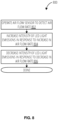
- FIG. 8 illustrates an LED control process 800 in accordance with one embodiment.
- an air flow sensor is operated to detect an air flow rate.
- an intensity of LED light is increased in response to an increase in the air flow rate or air agitation (or to ambient sound, which is proportional to air flow rate or agitation).
- an intensity of LED light emissions is decreased in response to a decrease in the air flow rate and/or agitation.
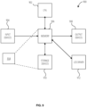
- Figure 9 illustrates an embodiment of a controller 900 to operate the sterilizing panel systems described herein.
- Input devices 904 comprise transducers that convert physical phenomenon into machine internal signals, typically electrical, optical or magnetic signals. Signals may also be wireless in the form of electromagnetic radiation in the radio frequency (RF) range but also potentially in the infrared or optical range. Examples of input devices 904 are buttons or keys which respond to touch or physical pressure from an object or proximity of an object to a surface, touch screens which respond to motion through space or across a plane, temperature sensors, and air pressure, sound, or air motion sensors. The signals from the input devices 904 are provided via various machine signal conductors (e.g., busses or network interfaces) and circuits to memory 906.
- RF radio frequency
- the memory 906 is typically what is known as a first or second level memory device, providing for storage (via configuration of matter or states of matter) of signals received from the input devices 904, instructions and data for controlling operation of the CPU 902, and signals from storage devices 910.
- the memory 906 and/or the storage devices 910 may store computer-executable instructions and thus forming logic 914 that when applied to and executed by the CPU 902 implement embodiments of the processes disclosed herein.
- Information stored in the memory 906 is typically directly accessible to the CPU 902 of the device. Signals input to the device cause the reconfiguration of the internal material/energy state of the memory 906, creating in essence a new machine configuration, influencing the behavior of the controller 900 by affecting the behavior of the CPU 902 with control signals (instructions) and data provided in conjunction with the control signals.
- Second or third level storage devices 910 may provide a slower but higher capacity machine memory capability.
- Examples of storage devices 910 are hard disks, optical disks, large capacity flash memories or other non-volatile memory technologies, and magnetic memories.
- the CPU 902 may cause the configuration of the memory 906 to be altered by signals in storage devices 910.
- the CPU 902 may cause data and instructions to be read from storage devices 910 in the memory 906 from which may then influence the operations of CPU 902 as instructions and data signals, and from which it may also be provided to the output devices 908.
- the CPU 902 may alter the content of the memory 906 by signaling to a machine interface of memory 906 to alter the internal configuration, and then converted signals to the storage devices 910 to alter its material internal configuration.
- data and instructions may be backed up from memory 906, which is often volatile, to storage devices 910, which are often non-volatile.
- Output devices 908 are transducers which convert signals received from the memory 906 into physical phenomenon such as vibrations in the air, or patterns of light on a machine display, or vibrations (i.e., haptic devices) or patterns of ink or other materials (i.e., printers and 3-D printers).
- the LED driver 912 receives signals from the memory 906 or the CPU 902 and converts them into electrical signals to the LEDs of the panels.
- the led driver 912 may also communicate signals to the memory 906 or the CPU 902.
- exemplary embodiments or aspects can include, but are not limited to:
- an apparatus may comprise a first plurality of ultraviolet light emitting diodes (UV LEDs) positioned in a first substrate; a first sheet of transparent material in thermal contact with at least a portion of the first plurality of ultraviolet light emitting diodes; a first frame surrounding the first substrate and the first sheet, forming a first panel; and a mobile platform to support the first panel over a floor, the mobile platform adapted to receive the first panel in a configuration such that light emitted from the first plurality of ultraviolet light emitting diodes is directed in an upward direction from the floor.
- UV LEDs ultraviolet light emitting diodes
- a second embodiment can include the apparatus of the first embodiment, wherein the transparent material is transparent ceramic aluminum.
- a third embodiment can include the apparatus of the first or second embodiments, the mobile platform comprising a release mechanism to engage and disengage the first panel.
- a fourth embodiment can include the apparatus of any of the first through third embodiments, wherein the first panel has a rectangular shape.
- a fifth embodiment can include the apparatus of any of the first through fourth embodiments, further comprising a second plurality of ultraviolet LEDs positioned on a second substrate; a second sheet of transparent material in thermal contact with the second ultraviolet LEDs; and a second frame surrounding the second substrate and the second sheet, forming a second panel; the mobile platform comprising a two-tiered bracket configured to receive the first panel and the second panel in a configuration such that the first sheet and the second sheet are aligned with and facing one another.
- a sixth embodiment can include the apparatus of the fifth embodiment, wherein the mobile platform comprises a release mechanism to engage and disengage the first panel.
- a seventh embodiment can include the apparatus of any of the fifth or sixth embodiment, further comprising the first panel comprising a first panel power port; the second panel comprising a second panel power port; and the mobile platform comprising a first platform power port and a second platform power port to respectively engage the first panel power port and second panel power port automatically when the first panel and second panel are placed on the mobile platform.
- An eighth embodiment can include the apparatus of any of the first through seventh embodiments, further comprising a second plurality of ultraviolet LEDs positioned on a second substrate; a second sheet of transparent material in thermal contact with the second ultraviolet LEDs; a second frame surrounding the second substrate and the second sheet, forming a second panel; the first panel comprising a first panel power port; the second panel comprising a second panel power port; and the mobile platform comprising a first platform power port and a second platform power port to respectively engage the first panel power port and second panel power port automatically when the first panel and second panel are placed on the mobile platform.
- a ninth embodiment can include the apparatus of the eighth embodiment, the mobile platform comprising a release mechanism to engage and disengage the first panel and the second panel.
- a tenth embodiment can include the apparatus of any of the first through ninth embodiments, wherein the first substrate comprises a geometry sized to fit within an autoclave.
- an assembly method may comprise positioning a first plurality of ultraviolet LEDs on a first substrate; fixing a first sheet of transparent material in thermal contact with the first ultraviolet LEDs; forming a first frame surrounding the first substrate and the first sheet, forming a first panel; and assembling a mobile platform to support the first panel over a floor, the mobile platform adapted to receive the first panel in a configuration such that light emitted from the first ultraviolet LEDs is directed in an upward direction from the floor.
- a twelfth embodiment can include the method of the eleventh embodiment, wherein the transparent material is transparent ceramic aluminum.
- a thirteenth embodiment can include the method of the eleventh or twelfth embodiments, the mobile platform comprising a release mechanism to engage and disengage the first panel.
- a fourteenth embodiment can include the method of any of the eleventh through thirteenth embodiments, wherein the first panel has a rectangular shape.
- a fifteenth embodiment can include the method of any of the eleventh through fourteenth embodiments, further comprising positioning a second plurality of ultraviolet LEDs on a second substrate; fixing a second sheet of transparent material in thermal contact with the second ultraviolet LEDs; forming a second frame surrounding the second substrate and the second sheet, forming a second panel; and equipping the mobile platform with a two-tiered bracket configured to receive the first panel and the second panel in a configuration such that the first sheet and the second sheet are aligned with and facing one another.
- a sixteenth embodiment can include the method of the fifteenth embodiment, further comprising equipping the mobile platform with a release mechanism to engage and disengage the first panel.
- a seventeenth embodiment can include the method of the fifteenth or sixteenth embodiment, further comprising providing the first panel with a first panel power port; providing the second panel with a second panel power port; and equipping the mobile platform with a first platform power port and a second platform power port to respectively engage the first panel power port and second panel power port automatically when the first panel and second panel are placed on the mobile platform.
- An eighteenth embodiment can include the method of any of the eleventh through seventeenth embodiments, further comprising positioning a second plurality of ultraviolet LEDs on a second substrate; fixing a second sheet of transparent material in thermal contact with the second ultraviolet LEDs; forming a second frame surrounding the second substrate and the second sheet, forming a second panel; equipping the first panel with a first panel power port; equipping the second panel with a second panel power port; and equipping the mobile platform with a first platform power port and a second platform power port to respectively engage the first panel power port and second panel power port automatically when the first panel and second panel are placed on the mobile platform.
- a nineteenth embodiment can include the method of the eighteenth embodiment, further comprising equipping the mobile platform with a release mechanism to engage and disengage the first panel and the second panel.
- a twentieth embodiment can include the method of any of the eleventh through nineteenth embodiments, further comprising sizing the first substrate with a geometry to fit within an autoclave.
- Circuitry in this context refers to electrical circuitry having at least one discrete electrical circuit, electrical circuitry having at least one integrated circuit, electrical circuitry having at least one application specific integrated circuit, circuitry forming a general purpose computing device configured by a computer program (e.g., a general purpose computer configured by a computer program which at least partially carries out processes or devices described herein, or a microprocessor configured by a computer program which at least partially carries out processes or devices described herein), circuitry forming a memory device (e.g., forms of random access memory), or circuitry forming a communications device (e.g., a modem, communications switch, or optical-electrical equipment).
- a computer program e.g., a general purpose computer configured by a computer program which at least partially carries out processes or devices described herein, or a microprocessor configured by a computer program which at least partially carries out processes or devices described herein
- circuitry forming a memory device e.g., forms of random access memory
- Fiberware in this context refers to software logic embodied as processor-executable instructions stored in read-only memories or media.
- Hardware in this context refers to logic embodied as analog or digital circuitry.
- Logic in this context refers to machine memory circuits, non transitory machine readable media, and/or circuitry which by way of its material and/or material-energy configuration comprises control and/or procedural signals, and/or settings and values (such as resistance, impedance, capacitance, inductance, current/voltage ratings, etc.), that may be applied to influence the operation of a device.
- Magnetic media, electronic circuits, electrical and optical memory (both volatile and nonvolatile), and firmware are examples of logic.
- Logic specifically excludes pure signals or software per se (however does not exclude machine memories comprising software and thereby forming configurations of matter).
- Programmable device in this context refers to an integrated circuit designed to be configured and/or reconfigured after manufacturing.
- the term "programmable processor” is another name for a programmable device herein.
- Programmable devices may include programmable processors, such as field programmable gate arrays (FPGAs), configurable hardware logic (CHL), and/or any other type programmable devices.
- Configuration of the programmable device is generally specified using a computer code or data such as a hardware description language (HDL), such as for example Verilog, VHDL, or the like.
- a programmable device may include an array of programmable logic blocks and a hierarchy of reconfigurable interconnects that allow the programmable logic blocks to be coupled to each other according to the descriptions in the HDL code.
- Each of the programmable logic blocks may be configured to perform complex combinational functions, or merely simple logic gates, such as AND, and XOR logic blocks.
- logic blocks also include memory elements, which may be simple latches, flip-flops, hereinafter also referred to as "flops," or more complex blocks of memory.
- signals may arrive at input terminals of the logic blocks at different times.
- Software in this context refers to logic implemented as processor-executable instructions in a machine memory (e.g. read/write volatile or nonvolatile memory or media).
- references to “one embodiment” or “an embodiment” do not necessarily refer to the same embodiment, although they may.
- the words “comprise,” “comprising,” and the like are to be construed in an inclusive sense as opposed to an exclusive or exhaustive sense; that is to say, in the sense of “including, but not limited to.” Words using the singular or plural number also include the plural or singular number respectively, unless expressly limited to a single one or multiple ones.
- the words “herein,” “above,” “below” and words of similar import when used in this application, refer to this application as a whole and not to any particular portions of this application.
- association operation may be carried out by an "associator” or “correlator”.
- switching may be carried out by a “switch”, selection by a “selector”, and so on.
- logic may be distributed throughout one or more devices, and/or may be comprised of combinations memory, media, processing circuits and controllers, other circuits, and so on. Therefore, in the interest of clarity and correctness logic may not always be distinctly illustrated in drawings of devices and systems, although it is inherently present therein.
- the techniques and procedures described herein may be implemented via logic distributed in one or more computing devices. The particular distribution and choice of logic will vary according to implementation.
- a signal bearing media include, but are not limited to, the following: recordable type media such as floppy disks, hard disk drives, CD ROMs, digital tape, flash drives, SD cards, solid state fixed or removable storage, and computer memory.
Landscapes
- Health & Medical Sciences (AREA)
- Life Sciences & Earth Sciences (AREA)
- Animal Behavior & Ethology (AREA)
- Veterinary Medicine (AREA)
- Public Health (AREA)
- General Health & Medical Sciences (AREA)
- Surgery (AREA)
- Epidemiology (AREA)
- Engineering & Computer Science (AREA)
- Molecular Biology (AREA)
- Medical Informatics (AREA)
- Heart & Thoracic Surgery (AREA)
- Biomedical Technology (AREA)
- Nuclear Medicine, Radiotherapy & Molecular Imaging (AREA)
- Led Device Packages (AREA)
- Apparatus For Disinfection Or Sterilisation (AREA)
- Agricultural Chemicals And Associated Chemicals (AREA)
Claims (11)
- Gerät (100, 400), umfassend:eine erste Vielzahl von Ultraviolettlicht emittierenden Dioden (106), die in einem ersten Substrat (114) positioniert sind;eine erste Lage aus transparentem Material (108) in thermischem Kontakt mit mindestens einem Anteil der ersten Vielzahl von Ultraviolettlicht emittierenden Dioden;einen ersten Rahmen (408), der das erste Substrat und die erste Lage umgibt, wodurch eine erste Platte (402) gebildet wird;eine mobile Plattform (110) zum Halten der ersten Platte über einem Boden, wobei die mobile Plattform eingerichtet ist, um die erste Platte in einer solchen Konfiguration zu empfangen, dass aus der ersten Vielzahl von Ultraviolettlicht emittierenden Dioden emittiertes Licht von dem Boden aus in eine aufwärtige Richtung geführt wird;eine zweite Vielzahl von Ultraviolettlicht emittierenden Dioden, die auf einem zweiten Substrat positioniert sind;eine zweite Lage aus transparentem Material in thermischem Kontakt mit mindestens einem Anteil der zweiten Vielzahl von Ultraviolettlicht emittierenden Dioden;einen zweiten Rahmen (404), der das zweite Substrat und die zweite Lage umgibt, wodurch eine zweite Platte gebildet wird; unddie mobile Plattform, umfassend eine zweigeteilte Halterung, die ausgestaltet ist, um die erste Platte und die zweite Platte in einer solchen Konfiguration zu empfangen, dass die erste Lage und die zweite Lage miteinander ausgerichtet sind und zueinander weisen.
- Gerät nach Anspruch 1, wobei das transparente Material transparentes keramisches Aluminium ist.
- Gerät nach Anspruch 1 oder Anspruch 2, wobei die mobile Plattform einen Freigabemechanismus umfasst, um in Eingriff mit der ersten Platte zu kommen und den Eingriff mit dieser zu lösen.
- Gerät nach einem der vorhergehenden Ansprüche, wobei die mobile Plattform einen Freigabemechanismus umfasst, um in Eingriff mit der ersten Platte zu kommen und den Eingriff mit dieser zu lösen.
- Gerät nach einem der vorhergehenden Ansprüche, des Weiteren umfassend:die erste Platte, umfassend einen Stromversorgungsanschluss der ersten Platte;die zweite Platte, umfassend einen Stromversorgungsanschluss der zweiten Platte; unddie mobile Plattform, umfassend einen ersten Plattformstromversorgungsanschluss und einen zweiten Plattformstromversorgungsanschluss, um automatisch in Eingriff mit dem Stromversorgungsanschluss der ersten Platte beziehungsweise dem Stromversorgungsanschluss der zweiten Platte zu kommen, wenn die erste Platte und die zweite Platte auf der mobilen Plattform platziert werden.
- Gerät nach einem der vorhergehenden Ansprüche, wobei das erste Substrat eine Geometrie umfasst, die so bemessen ist, dass es in einen Autoklaven passt.
- Montageverfahren (300), umfassend:Positionieren (302) einer ersten Vielzahl von Ultraviolettlicht emittierenden Dioden (106) auf einem ersten Substrat (114);Fixieren (304) einer ersten Lage aus transparentem Material (108) in thermischem Kontakt mit mindestens einem Anteil der ersten Vielzahl von Ultraviolettlicht emittierenden Dioden;Bilden (306) eines ersten Rahmens (408), der das erste Substrat und die erste Lage umgibt, wodurch eine erste Platte (402) gebildet wird;Montieren (308) einer mobilen Plattform (110) zum Halten der ersten Platte über einem Boden, wobei die mobile Plattform eingerichtet ist, um die erste Platte in einer solchen Konfiguration zu empfangen, dass aus der ersten Vielzahl von Ultraviolettlicht emittierenden Dioden emittiertes Licht von dem Boden aus in eine aufwärtige Richtung geführt wird;Positionieren einer zweiten Vielzahl von Ultraviolettlicht emittierenden Dioden auf einem zweiten Substrat;Fixieren einer zweiten Lage aus transparentem Material in thermischem Kontakt mit mindestens einem Anteil der zweiten Vielzahl von Ultraviolettlicht emittierenden Dioden;Bilden eines zweiten Rahmens (404), der das zweite Substrat und die zweite Lage umgibt, wodurch eine zweite Platte gebildet wird; undAusstatten der mobilen Plattform mit einer zweigeteilten Halterung, die ausgestaltet ist, um die erste Platte und die zweite Platte in einer solchen Konfiguration zu empfangen, dass die erste Lage und die zweite Lage miteinander ausgerichtet sind und zueinander weisen.
- Verfahren nach Anspruch 7, wobei das transparente Material transparentes keramisches Aluminium ist.
- Verfahren nach Anspruch 7 oder 8, des Weiteren umfassend Ausstatten der mobilen Plattform mit einem Freigabemechanismus, um in Eingriff mit der ersten Platte zu kommen und den Eingriff mit dieser zu lösen.
- Verfahren nach einem der Ansprüche 7 bis 9, des Weiteren umfassend:Bereitstellen der ersten Platte mit einem Stromversorgungsanschluss der ersten Platte;Bereitstellen der zweiten Platte mit einem Stromversorgungsanschluss der zweiten Platte; undAusstatten der mobilen Plattform mit einem ersten Plattformstromversorgungsanschluss und einem zweiten Plattformstromversorgungsanschluss, um automatisch in Eingriff mit dem Stromversorgungsanschluss der ersten Platte beziehungsweise dem Stromversorgungsanschluss der zweiten Platte zu kommen, wenn die erste Platte und die zweite Platte auf der mobilen Plattform platziert werden.
- Verfahren nach einem der Ansprüche 7 bis 10, des Weiteren umfassend Bemessen des ersten Substrats mit einer Geometrie, so dass es in einen Autoklaven passt.
Applications Claiming Priority (2)
| Application Number | Priority Date | Filing Date | Title |
|---|---|---|---|
| US201762562036P | 2017-09-22 | 2017-09-22 | |
| PCT/US2018/052054 WO2019060617A2 (en) | 2017-09-22 | 2018-09-20 | TABLE OF SURGICAL INSTRUMENTS STERILIZING |
Publications (3)
| Publication Number | Publication Date |
|---|---|
| EP3684285A2 EP3684285A2 (de) | 2020-07-29 |
| EP3684285A4 EP3684285A4 (de) | 2021-06-09 |
| EP3684285B1 true EP3684285B1 (de) | 2024-03-13 |
Family
ID=65810625
Family Applications (1)
| Application Number | Title | Priority Date | Filing Date |
|---|---|---|---|
| EP18859558.1A Active EP3684285B1 (de) | 2017-09-22 | 2018-09-20 | Chirurgischer instrumententisch mit sterilisationsfunktion |
Country Status (11)
| Country | Link |
|---|---|
| US (4) | US11331399B2 (de) |
| EP (1) | EP3684285B1 (de) |
| JP (1) | JP7296372B2 (de) |
| AU (2) | AU2018335399A1 (de) |
| CA (1) | CA3076618A1 (de) |
| DK (1) | DK3684285T3 (de) |
| ES (1) | ES2979974T3 (de) |
| FI (1) | FI3684285T3 (de) |
| PL (1) | PL3684285T3 (de) |
| PT (1) | PT3684285T (de) |
| WO (1) | WO2019060617A2 (de) |
Families Citing this family (5)
| Publication number | Priority date | Publication date | Assignee | Title |
|---|---|---|---|---|
| US10639393B1 (en) * | 2015-11-16 | 2020-05-05 | Stephen J. Sustrick | Fluid system with integrated disinfecting optics |
| JP7296372B2 (ja) * | 2017-09-22 | 2023-06-22 | マンセル、ジョン | 殺菌用外科用器具テーブル |
| CN110840569B (zh) * | 2019-11-26 | 2021-01-15 | 南阳市中心医院 | 医学影像诊断辅助设备 |
| CN111110360B (zh) * | 2019-12-24 | 2020-12-22 | 江苏福维健康科技有限公司 | 一种手术器械台器械摆放架 |
| DK202400375A1 (en) * | 2024-05-02 | 2025-11-17 | Uv Medico As | Surgery tool decontamination table |
Citations (1)
| Publication number | Priority date | Publication date | Assignee | Title |
|---|---|---|---|---|
| US20080265179A1 (en) * | 2007-04-27 | 2008-10-30 | Havens William H | Sterilization apparatus |
Family Cites Families (26)
| Publication number | Priority date | Publication date | Assignee | Title |
|---|---|---|---|---|
| US6911177B2 (en) * | 2000-09-19 | 2005-06-28 | Jeffrey L. Deal | Ultraviolet area sterilizer and method of area sterilization using ultraviolet radiation |
| US6612889B1 (en) * | 2000-10-27 | 2003-09-02 | Science Applications International Corporation | Method for making a light-emitting panel |
| US20030034459A1 (en) * | 2001-08-20 | 2003-02-20 | Bonin Pete J. | Hygienic cabinet |
| US20070023710A1 (en) * | 2005-07-08 | 2007-02-01 | Amarante Technologies, Inc. | Closed-loop control of ultraviolet (UV) sterilization systems |
| US20090206674A1 (en) * | 2005-07-19 | 2009-08-20 | Olympus Medical Systems Corp. | Medical instrument storage system |
| JP4756941B2 (ja) * | 2005-07-19 | 2011-08-24 | オリンパスメディカルシステムズ株式会社 | 医療器具保管装置 |
| US7608842B2 (en) | 2007-04-26 | 2009-10-27 | University Of Washington | Driving scanning fiber devices with variable frequency drive signals |
| US8074815B2 (en) * | 2007-05-25 | 2011-12-13 | Jeffrey Gerstner | Multi-level rack system with ultraviolet light for supporting surgical tools |
| US20100266445A1 (en) * | 2009-04-21 | 2010-10-21 | Kenneth L. Campagna | Portable antimicrobial ultra violet sterilizer |
| US8662705B2 (en) * | 2010-03-30 | 2014-03-04 | Virwall Systems, Inc. | Flexible ultraviolet LED sanitizing apparatus |
| US20130259742A1 (en) * | 2012-01-05 | 2013-10-03 | Rjg Associates | Sanitizing devices and methods of their use |
| US20180104368A1 (en) * | 2012-04-16 | 2018-04-19 | Sensor Electronic Technology, Inc. | Ultraviolet-Based Sterilization |
| KR20130131958A (ko) | 2012-05-25 | 2013-12-04 | 주식회사 소냐엘에스 | 자외선 살균장치 및 이것을 이용한 수납장, 테이블 및 도마 |
| WO2014100493A1 (en) | 2012-12-19 | 2014-06-26 | Helios Innovative Technologies Inc. | Sterilization units, systems, and methods |
| WO2014115146A1 (en) * | 2013-01-24 | 2014-07-31 | Atlantium Technologies Ltd. | Method and apparatus for liquid disinfection by light emitted from light emitting diodes |
| CN105518380B (zh) * | 2013-09-06 | 2019-01-29 | 传感器电子技术股份有限公司 | 紫外线漫射照射 |
| JP6726178B2 (ja) * | 2014-10-28 | 2020-07-22 | センサー エレクトロニック テクノロジー インコーポレイテッド | 紫外線素子を用いた接着装置 |
| WO2016161461A1 (en) * | 2015-04-03 | 2016-10-06 | Kovacs Steven Gabor | Disposable sanitary tray and bedside tables |
| US10549001B2 (en) * | 2015-07-08 | 2020-02-04 | Clean Light Laboratories Llc | System and device for sanitizing personal use items |
| KR20170022190A (ko) * | 2015-08-19 | 2017-03-02 | 전용복 | 자외선 살균 기능을 갖는 싱크대 |
| US12268788B2 (en) * | 2016-05-24 | 2025-04-08 | Signify Holding, B.V. | UV module within consumer machines |
| US10898603B2 (en) * | 2016-12-05 | 2021-01-26 | Harbor Innovations, LLC | System and apparatus thereof for destroying pathogens associated with footwear |
| JP7296372B2 (ja) * | 2017-09-22 | 2023-06-22 | マンセル、ジョン | 殺菌用外科用器具テーブル |
| CN114007657A (zh) * | 2019-06-25 | 2022-02-01 | Fka分销有限公司 | Uv消毒装置 |
| US11272793B2 (en) * | 2019-07-08 | 2022-03-15 | Pluie, Inc. | Diaper changing tables and methods of using thereof |
| US20210113723A1 (en) * | 2019-10-17 | 2021-04-22 | Raffel Systems, Llc | Uv-sanitizing apparatuses and systems |
-
2018
- 2018-09-20 JP JP2020516639A patent/JP7296372B2/ja active Active
- 2018-09-20 US US16/647,819 patent/US11331399B2/en active Active
- 2018-09-20 DK DK18859558.1T patent/DK3684285T3/da active
- 2018-09-20 WO PCT/US2018/052054 patent/WO2019060617A2/en not_active Ceased
- 2018-09-20 EP EP18859558.1A patent/EP3684285B1/de active Active
- 2018-09-20 FI FIEP18859558.1T patent/FI3684285T3/fi active
- 2018-09-20 AU AU2018335399A patent/AU2018335399A1/en not_active Abandoned
- 2018-09-20 ES ES18859558T patent/ES2979974T3/es active Active
- 2018-09-20 PT PT188595581T patent/PT3684285T/pt unknown
- 2018-09-20 PL PL18859558.1T patent/PL3684285T3/pl unknown
- 2018-09-20 CA CA3076618A patent/CA3076618A1/en active Pending
-
2022
- 2022-05-02 US US17/734,296 patent/US11779669B2/en active Active
-
2023
- 2023-09-05 US US18/242,435 patent/US12168078B2/en active Active
-
2024
- 2024-08-16 AU AU2024205808A patent/AU2024205808A1/en active Pending
- 2024-11-12 US US18/944,236 patent/US20250065002A1/en active Pending
Patent Citations (1)
| Publication number | Priority date | Publication date | Assignee | Title |
|---|---|---|---|---|
| US20080265179A1 (en) * | 2007-04-27 | 2008-10-30 | Havens William H | Sterilization apparatus |
Also Published As
| Publication number | Publication date |
|---|---|
| AU2018335399A1 (en) | 2020-04-09 |
| US20200215212A1 (en) | 2020-07-09 |
| US11331399B2 (en) | 2022-05-17 |
| JP7296372B2 (ja) | 2023-06-22 |
| AU2024205808A1 (en) | 2024-09-05 |
| JP2020534093A (ja) | 2020-11-26 |
| DK3684285T3 (da) | 2024-05-21 |
| EP3684285A4 (de) | 2021-06-09 |
| PT3684285T (pt) | 2024-05-17 |
| US11779669B2 (en) | 2023-10-10 |
| CA3076618A1 (en) | 2019-03-28 |
| US12168078B2 (en) | 2024-12-17 |
| US20220257815A1 (en) | 2022-08-18 |
| ES2979974T3 (es) | 2024-09-27 |
| EP3684285A2 (de) | 2020-07-29 |
| WO2019060617A2 (en) | 2019-03-28 |
| US20250065002A1 (en) | 2025-02-27 |
| FI3684285T3 (fi) | 2024-05-16 |
| PL3684285T3 (pl) | 2024-07-15 |
| US20230405165A1 (en) | 2023-12-21 |
| WO2019060617A3 (en) | 2019-05-23 |
Similar Documents
| Publication | Publication Date | Title |
|---|---|---|
| US12168078B2 (en) | Sterilizing surgical instrument table | |
| US10543290B2 (en) | Ultraviolet illuminator for object disinfection | |
| EP2440287B1 (de) | Vorrichtung für die photodynamische therapie | |
| JP7835742B2 (ja) | 生物学的流体処理システム用のモジュール式光装置 | |
| EP2882492B1 (de) | Led-basierte phototherapieplatte zum einbau in eine röntgenkassettenschale eines inkubators | |
| CN111201044A (zh) | 用于管理设备消毒的系统和方法 | |
| EP4290335A2 (de) | Computerinnenarchitektur | |
| US20180064953A1 (en) | Phototherapy device | |
| EP2292332B1 (de) | Arbeitsstation | |
| US9452235B2 (en) | Incubator with air purification | |
| CN109328091A (zh) | 光处置设备的热保护 | |
| EP3449181B1 (de) | Modulare leuchttafel | |
| DE502004003854D1 (de) | Messvorrichtung mit einer auf Messzellen gelagerten Tragplatte für eine Person | |
| US20230031285A1 (en) | System for Disinfecting a Touch Screen | |
| AU2015292418B2 (en) | A system and method to physically and electronically configure an air mattress system for multiple users | |
| US20210353799A1 (en) | Ultraviolet (uv) disinfector | |
| WO2022020966A1 (en) | Ultraviolet disinfector and related methods for disinfecting articles | |
| US20170158429A1 (en) | Reticle Rack System | |
| WO2021142047A1 (en) | System for disinfecting a card reader | |
| US20170215254A1 (en) | Control switch including sensors, acquisition circuit, change circuit, and control circuit | |
| US11235606B2 (en) | Sensor for emulsion irradiation | |
| US11667079B2 (en) | Stereolithography apparatus equipped with shutter cooling channel | |
| WO2023011923A1 (en) | Disinfecting luminaire using switchable mirrors |
Legal Events
| Date | Code | Title | Description |
|---|---|---|---|
| STAA | Information on the status of an ep patent application or granted ep patent |
Free format text: STATUS: THE INTERNATIONAL PUBLICATION HAS BEEN MADE |
|
| PUAI | Public reference made under article 153(3) epc to a published international application that has entered the european phase |
Free format text: ORIGINAL CODE: 0009012 |
|
| STAA | Information on the status of an ep patent application or granted ep patent |
Free format text: STATUS: REQUEST FOR EXAMINATION WAS MADE |
|
| 17P | Request for examination filed |
Effective date: 20200331 |
|
| AK | Designated contracting states |
Kind code of ref document: A2 Designated state(s): AL AT BE BG CH CY CZ DE DK EE ES FI FR GB GR HR HU IE IS IT LI LT LU LV MC MK MT NL NO PL PT RO RS SE SI SK SM TR |
|
| AX | Request for extension of the european patent |
Extension state: BA ME |
|
| DAV | Request for validation of the european patent (deleted) | ||
| DAX | Request for extension of the european patent (deleted) | ||
| A4 | Supplementary search report drawn up and despatched |
Effective date: 20210512 |
|
| RIC1 | Information provided on ipc code assigned before grant |
Ipc: A61B 50/15 20160101AFI20210506BHEP Ipc: A61B 50/13 20160101ALI20210506BHEP Ipc: A61B 50/24 20160101ALI20210506BHEP Ipc: A61L 2/10 20060101ALI20210506BHEP Ipc: A61G 12/00 20060101ALI20210506BHEP |
|
| STAA | Information on the status of an ep patent application or granted ep patent |
Free format text: STATUS: EXAMINATION IS IN PROGRESS |
|
| 17Q | First examination report despatched |
Effective date: 20220930 |
|
| P01 | Opt-out of the competence of the unified patent court (upc) registered |
Effective date: 20230522 |
|
| GRAP | Despatch of communication of intention to grant a patent |
Free format text: ORIGINAL CODE: EPIDOSNIGR1 |
|
| STAA | Information on the status of an ep patent application or granted ep patent |
Free format text: STATUS: GRANT OF PATENT IS INTENDED |
|
| INTG | Intention to grant announced |
Effective date: 20231020 |
|
| GRAS | Grant fee paid |
Free format text: ORIGINAL CODE: EPIDOSNIGR3 |
|
| GRAA | (expected) grant |
Free format text: ORIGINAL CODE: 0009210 |
|
| STAA | Information on the status of an ep patent application or granted ep patent |
Free format text: STATUS: THE PATENT HAS BEEN GRANTED |
|
| AK | Designated contracting states |
Kind code of ref document: B1 Designated state(s): AL AT BE BG CH CY CZ DE DK EE ES FI FR GB GR HR HU IE IS IT LI LT LU LV MC MK MT NL NO PL PT RO RS SE SI SK SM TR |
|
| REG | Reference to a national code |
Ref country code: GB Ref legal event code: FG4D |
|
| REG | Reference to a national code |
Ref country code: CH Ref legal event code: EP |
|
| REG | Reference to a national code |
Ref country code: DE Ref legal event code: R096 Ref document number: 602018066679 Country of ref document: DE |
|
| REG | Reference to a national code |
Ref country code: IE Ref legal event code: FG4D |
|
| REG | Reference to a national code |
Ref country code: FI Ref legal event code: FGE |
|
| REG | Reference to a national code |
Ref country code: PT Ref legal event code: SC4A Ref document number: 3684285 Country of ref document: PT Date of ref document: 20240517 Kind code of ref document: T Free format text: AVAILABILITY OF NATIONAL TRANSLATION Effective date: 20240514 |
|
| REG | Reference to a national code |
Ref country code: DK Ref legal event code: T3 Effective date: 20240516 |
|
| REG | Reference to a national code |
Ref country code: SE Ref legal event code: TRGR |
|
| REG | Reference to a national code |
Ref country code: NL Ref legal event code: FP |
|
| PG25 | Lapsed in a contracting state [announced via postgrant information from national office to epo] |
Ref country code: LT Free format text: LAPSE BECAUSE OF FAILURE TO SUBMIT A TRANSLATION OF THE DESCRIPTION OR TO PAY THE FEE WITHIN THE PRESCRIBED TIME-LIMIT Effective date: 20240313 |
|
| REG | Reference to a national code |
Ref country code: LT Ref legal event code: MG9D |
|
| PG25 | Lapsed in a contracting state [announced via postgrant information from national office to epo] |
Ref country code: GR Free format text: LAPSE BECAUSE OF FAILURE TO SUBMIT A TRANSLATION OF THE DESCRIPTION OR TO PAY THE FEE WITHIN THE PRESCRIBED TIME-LIMIT Effective date: 20240614 |
|
| PG25 | Lapsed in a contracting state [announced via postgrant information from national office to epo] |
Ref country code: HR Free format text: LAPSE BECAUSE OF FAILURE TO SUBMIT A TRANSLATION OF THE DESCRIPTION OR TO PAY THE FEE WITHIN THE PRESCRIBED TIME-LIMIT Effective date: 20240313 Ref country code: RS Free format text: LAPSE BECAUSE OF FAILURE TO SUBMIT A TRANSLATION OF THE DESCRIPTION OR TO PAY THE FEE WITHIN THE PRESCRIBED TIME-LIMIT Effective date: 20240613 |
|
| PG25 | Lapsed in a contracting state [announced via postgrant information from national office to epo] |
Ref country code: RS Free format text: LAPSE BECAUSE OF FAILURE TO SUBMIT A TRANSLATION OF THE DESCRIPTION OR TO PAY THE FEE WITHIN THE PRESCRIBED TIME-LIMIT Effective date: 20240613 Ref country code: LT Free format text: LAPSE BECAUSE OF FAILURE TO SUBMIT A TRANSLATION OF THE DESCRIPTION OR TO PAY THE FEE WITHIN THE PRESCRIBED TIME-LIMIT Effective date: 20240313 Ref country code: HR Free format text: LAPSE BECAUSE OF FAILURE TO SUBMIT A TRANSLATION OF THE DESCRIPTION OR TO PAY THE FEE WITHIN THE PRESCRIBED TIME-LIMIT Effective date: 20240313 Ref country code: GR Free format text: LAPSE BECAUSE OF FAILURE TO SUBMIT A TRANSLATION OF THE DESCRIPTION OR TO PAY THE FEE WITHIN THE PRESCRIBED TIME-LIMIT Effective date: 20240614 Ref country code: BG Free format text: LAPSE BECAUSE OF FAILURE TO SUBMIT A TRANSLATION OF THE DESCRIPTION OR TO PAY THE FEE WITHIN THE PRESCRIBED TIME-LIMIT Effective date: 20240313 |
|
| PG25 | Lapsed in a contracting state [announced via postgrant information from national office to epo] |
Ref country code: LV Free format text: LAPSE BECAUSE OF FAILURE TO SUBMIT A TRANSLATION OF THE DESCRIPTION OR TO PAY THE FEE WITHIN THE PRESCRIBED TIME-LIMIT Effective date: 20240313 |
|
| REG | Reference to a national code |
Ref country code: ES Ref legal event code: FG2A Ref document number: 2979974 Country of ref document: ES Kind code of ref document: T3 Effective date: 20240927 |
|
| PG25 | Lapsed in a contracting state [announced via postgrant information from national office to epo] |
Ref country code: SM Free format text: LAPSE BECAUSE OF FAILURE TO SUBMIT A TRANSLATION OF THE DESCRIPTION OR TO PAY THE FEE WITHIN THE PRESCRIBED TIME-LIMIT Effective date: 20240313 |
|
| PG25 | Lapsed in a contracting state [announced via postgrant information from national office to epo] |
Ref country code: CZ Free format text: LAPSE BECAUSE OF FAILURE TO SUBMIT A TRANSLATION OF THE DESCRIPTION OR TO PAY THE FEE WITHIN THE PRESCRIBED TIME-LIMIT Effective date: 20240313 Ref country code: EE Free format text: LAPSE BECAUSE OF FAILURE TO SUBMIT A TRANSLATION OF THE DESCRIPTION OR TO PAY THE FEE WITHIN THE PRESCRIBED TIME-LIMIT Effective date: 20240313 |
|
| PG25 | Lapsed in a contracting state [announced via postgrant information from national office to epo] |
Ref country code: SK Free format text: LAPSE BECAUSE OF FAILURE TO SUBMIT A TRANSLATION OF THE DESCRIPTION OR TO PAY THE FEE WITHIN THE PRESCRIBED TIME-LIMIT Effective date: 20240313 |
|
| PG25 | Lapsed in a contracting state [announced via postgrant information from national office to epo] |
Ref country code: SM Free format text: LAPSE BECAUSE OF FAILURE TO SUBMIT A TRANSLATION OF THE DESCRIPTION OR TO PAY THE FEE WITHIN THE PRESCRIBED TIME-LIMIT Effective date: 20240313 Ref country code: SK Free format text: LAPSE BECAUSE OF FAILURE TO SUBMIT A TRANSLATION OF THE DESCRIPTION OR TO PAY THE FEE WITHIN THE PRESCRIBED TIME-LIMIT Effective date: 20240313 Ref country code: RO Free format text: LAPSE BECAUSE OF FAILURE TO SUBMIT A TRANSLATION OF THE DESCRIPTION OR TO PAY THE FEE WITHIN THE PRESCRIBED TIME-LIMIT Effective date: 20240313 Ref country code: EE Free format text: LAPSE BECAUSE OF FAILURE TO SUBMIT A TRANSLATION OF THE DESCRIPTION OR TO PAY THE FEE WITHIN THE PRESCRIBED TIME-LIMIT Effective date: 20240313 Ref country code: CZ Free format text: LAPSE BECAUSE OF FAILURE TO SUBMIT A TRANSLATION OF THE DESCRIPTION OR TO PAY THE FEE WITHIN THE PRESCRIBED TIME-LIMIT Effective date: 20240313 |
|
| REG | Reference to a national code |
Ref country code: DE Ref legal event code: R097 Ref document number: 602018066679 Country of ref document: DE |
|
| PLBE | No opposition filed within time limit |
Free format text: ORIGINAL CODE: 0009261 |
|
| STAA | Information on the status of an ep patent application or granted ep patent |
Free format text: STATUS: NO OPPOSITION FILED WITHIN TIME LIMIT |
|
| 26N | No opposition filed |
Effective date: 20241216 |
|
| PG25 | Lapsed in a contracting state [announced via postgrant information from national office to epo] |
Ref country code: SI Free format text: LAPSE BECAUSE OF FAILURE TO SUBMIT A TRANSLATION OF THE DESCRIPTION OR TO PAY THE FEE WITHIN THE PRESCRIBED TIME-LIMIT Effective date: 20240313 Ref country code: MC Free format text: LAPSE BECAUSE OF FAILURE TO SUBMIT A TRANSLATION OF THE DESCRIPTION OR TO PAY THE FEE WITHIN THE PRESCRIBED TIME-LIMIT Effective date: 20240313 |
|
| PG25 | Lapsed in a contracting state [announced via postgrant information from national office to epo] |
Ref country code: LU Free format text: LAPSE BECAUSE OF NON-PAYMENT OF DUE FEES Effective date: 20240920 |
|
| REG | Reference to a national code |
Ref country code: CH Ref legal event code: U11 Free format text: ST27 STATUS EVENT CODE: U-0-0-U10-U11 (AS PROVIDED BY THE NATIONAL OFFICE) Effective date: 20251001 |
|
| PGFP | Annual fee paid to national office [announced via postgrant information from national office to epo] |
Ref country code: PT Payment date: 20250903 Year of fee payment: 8 Ref country code: FI Payment date: 20250925 Year of fee payment: 8 |
|
| PGFP | Annual fee paid to national office [announced via postgrant information from national office to epo] |
Ref country code: DK Payment date: 20250925 Year of fee payment: 8 Ref country code: DE Payment date: 20250929 Year of fee payment: 8 |
|
| PGFP | Annual fee paid to national office [announced via postgrant information from national office to epo] |
Ref country code: NO Payment date: 20250929 Year of fee payment: 8 |
|
| PGFP | Annual fee paid to national office [announced via postgrant information from national office to epo] |
Ref country code: TR Payment date: 20250908 Year of fee payment: 8 Ref country code: NL Payment date: 20250926 Year of fee payment: 8 Ref country code: PL Payment date: 20250905 Year of fee payment: 8 Ref country code: IT Payment date: 20250919 Year of fee payment: 8 |
|
| PGFP | Annual fee paid to national office [announced via postgrant information from national office to epo] |
Ref country code: BE Payment date: 20250929 Year of fee payment: 8 Ref country code: GB Payment date: 20250929 Year of fee payment: 8 |
|
| PGFP | Annual fee paid to national office [announced via postgrant information from national office to epo] |
Ref country code: AT Payment date: 20250929 Year of fee payment: 8 Ref country code: FR Payment date: 20250925 Year of fee payment: 8 |
|
| PGFP | Annual fee paid to national office [announced via postgrant information from national office to epo] |
Ref country code: SE Payment date: 20250927 Year of fee payment: 8 |
|
| PGFP | Annual fee paid to national office [announced via postgrant information from national office to epo] |
Ref country code: IE Payment date: 20250929 Year of fee payment: 8 |
|
| PGFP | Annual fee paid to national office [announced via postgrant information from national office to epo] |
Ref country code: IS Payment date: 20250915 Year of fee payment: 8 |
|
| PGFP | Annual fee paid to national office [announced via postgrant information from national office to epo] |
Ref country code: CH Payment date: 20251001 Year of fee payment: 8 |
|
| PG25 | Lapsed in a contracting state [announced via postgrant information from national office to epo] |
Ref country code: CY Free format text: LAPSE BECAUSE OF FAILURE TO SUBMIT A TRANSLATION OF THE DESCRIPTION OR TO PAY THE FEE WITHIN THE PRESCRIBED TIME-LIMIT; INVALID AB INITIO Effective date: 20180920 |
|
| PGFP | Annual fee paid to national office [announced via postgrant information from national office to epo] |
Ref country code: ES Payment date: 20251001 Year of fee payment: 8 |
|
| PG25 | Lapsed in a contracting state [announced via postgrant information from national office to epo] |
Ref country code: HU Free format text: LAPSE BECAUSE OF FAILURE TO SUBMIT A TRANSLATION OF THE DESCRIPTION OR TO PAY THE FEE WITHIN THE PRESCRIBED TIME-LIMIT; INVALID AB INITIO Effective date: 20180920 |