EP3683913B1 - Restart determination device, internal-short determination device, restart determination method, and computer program - Google Patents
Restart determination device, internal-short determination device, restart determination method, and computer program Download PDFInfo
- Publication number
- EP3683913B1 EP3683913B1 EP18881887.6A EP18881887A EP3683913B1 EP 3683913 B1 EP3683913 B1 EP 3683913B1 EP 18881887 A EP18881887 A EP 18881887A EP 3683913 B1 EP3683913 B1 EP 3683913B1
- Authority
- EP
- European Patent Office
- Prior art keywords
- voltage value
- restart
- value
- engine
- energy storage
- Prior art date
- Legal status (The legal status is an assumption and is not a legal conclusion. Google has not performed a legal analysis and makes no representation as to the accuracy of the status listed.)
- Active
Links
- 238000000034 method Methods 0.000 title claims description 23
- 238000004590 computer program Methods 0.000 title claims description 6
- 238000004146 energy storage Methods 0.000 claims description 50
- 238000004364 calculation method Methods 0.000 claims description 28
- 239000007858 starting material Substances 0.000 claims description 14
- 210000004027 cell Anatomy 0.000 description 28
- 239000011149 active material Substances 0.000 description 19
- 238000001514 detection method Methods 0.000 description 9
- 230000006866 deterioration Effects 0.000 description 8
- 229910000978 Pb alloy Inorganic materials 0.000 description 7
- YADSGOSSYOOKMP-UHFFFAOYSA-N dioxolead Chemical compound O=[Pb]=O YADSGOSSYOOKMP-UHFFFAOYSA-N 0.000 description 6
- PIJPYDMVFNTHIP-UHFFFAOYSA-L lead sulfate Chemical compound [PbH4+2].[O-]S([O-])(=O)=O PIJPYDMVFNTHIP-UHFFFAOYSA-L 0.000 description 6
- 238000012986 modification Methods 0.000 description 6
- 230000004048 modification Effects 0.000 description 6
- 239000002253 acid Substances 0.000 description 5
- 238000010586 diagram Methods 0.000 description 5
- 230000006870 function Effects 0.000 description 5
- 230000007423 decrease Effects 0.000 description 4
- 239000008151 electrolyte solution Substances 0.000 description 4
- 238000012545 processing Methods 0.000 description 4
- 229920003002 synthetic resin Polymers 0.000 description 3
- 239000000057 synthetic resin Substances 0.000 description 3
- QAOWNCQODCNURD-UHFFFAOYSA-N Sulfuric acid Chemical compound OS(O)(=O)=O QAOWNCQODCNURD-UHFFFAOYSA-N 0.000 description 2
- 239000000654 additive Substances 0.000 description 2
- 230000000996 additive effect Effects 0.000 description 2
- 210000000988 bone and bone Anatomy 0.000 description 2
- 210000001787 dendrite Anatomy 0.000 description 2
- 238000007599 discharging Methods 0.000 description 2
- 229910052751 metal Inorganic materials 0.000 description 2
- 239000002184 metal Substances 0.000 description 2
- 230000035515 penetration Effects 0.000 description 2
- 230000002093 peripheral effect Effects 0.000 description 2
- 239000012466 permeate Substances 0.000 description 2
- 238000003466 welding Methods 0.000 description 2
- HBBGRARXTFLTSG-UHFFFAOYSA-N Lithium ion Chemical compound [Li+] HBBGRARXTFLTSG-UHFFFAOYSA-N 0.000 description 1
- 241000220317 Rosa Species 0.000 description 1
- 238000004891 communication Methods 0.000 description 1
- 238000011109 contamination Methods 0.000 description 1
- 239000013078 crystal Substances 0.000 description 1
- 230000008021 deposition Effects 0.000 description 1
- 238000005265 energy consumption Methods 0.000 description 1
- 238000011156 evaluation Methods 0.000 description 1
- 238000002474 experimental method Methods 0.000 description 1
- 239000011521 glass Substances 0.000 description 1
- 239000011810 insulating material Substances 0.000 description 1
- 239000007788 liquid Substances 0.000 description 1
- 229910001416 lithium ion Inorganic materials 0.000 description 1
- 238000005259 measurement Methods 0.000 description 1
- 238000000465 moulding Methods 0.000 description 1
- 238000005192 partition Methods 0.000 description 1
- 239000002244 precipitate Substances 0.000 description 1
- 238000012360 testing method Methods 0.000 description 1
- 238000012795 verification Methods 0.000 description 1
- XLYOFNOQVPJJNP-UHFFFAOYSA-N water Substances O XLYOFNOQVPJJNP-UHFFFAOYSA-N 0.000 description 1
Images


Classifications
-
- H—ELECTRICITY
- H02—GENERATION; CONVERSION OR DISTRIBUTION OF ELECTRIC POWER
- H02J—CIRCUIT ARRANGEMENTS OR SYSTEMS FOR SUPPLYING OR DISTRIBUTING ELECTRIC POWER; SYSTEMS FOR STORING ELECTRIC ENERGY
- H02J7/00—Circuit arrangements for charging or depolarising batteries or for supplying loads from batteries
- H02J7/0047—Circuit arrangements for charging or depolarising batteries or for supplying loads from batteries with monitoring or indicating devices or circuits
- H02J7/005—Detection of state of health [SOH]
-
- H—ELECTRICITY
- H01—ELECTRIC ELEMENTS
- H01M—PROCESSES OR MEANS, e.g. BATTERIES, FOR THE DIRECT CONVERSION OF CHEMICAL ENERGY INTO ELECTRICAL ENERGY
- H01M10/00—Secondary cells; Manufacture thereof
- H01M10/42—Methods or arrangements for servicing or maintenance of secondary cells or secondary half-cells
- H01M10/48—Accumulators combined with arrangements for measuring, testing or indicating the condition of cells, e.g. the level or density of the electrolyte
-
- F—MECHANICAL ENGINEERING; LIGHTING; HEATING; WEAPONS; BLASTING
- F02—COMBUSTION ENGINES; HOT-GAS OR COMBUSTION-PRODUCT ENGINE PLANTS
- F02D—CONTROLLING COMBUSTION ENGINES
- F02D29/00—Controlling engines, such controlling being peculiar to the devices driven thereby, the devices being other than parts or accessories essential to engine operation, e.g. controlling of engines by signals external thereto
- F02D29/02—Controlling engines, such controlling being peculiar to the devices driven thereby, the devices being other than parts or accessories essential to engine operation, e.g. controlling of engines by signals external thereto peculiar to engines driving vehicles; peculiar to engines driving variable pitch propellers
-
- F—MECHANICAL ENGINEERING; LIGHTING; HEATING; WEAPONS; BLASTING
- F02—COMBUSTION ENGINES; HOT-GAS OR COMBUSTION-PRODUCT ENGINE PLANTS
- F02N—STARTING OF COMBUSTION ENGINES; STARTING AIDS FOR SUCH ENGINES, NOT OTHERWISE PROVIDED FOR
- F02N11/00—Starting of engines by means of electric motors
- F02N11/08—Circuits or control means specially adapted for starting of engines
- F02N11/0814—Circuits or control means specially adapted for starting of engines comprising means for controlling automatic idle-start-stop
- F02N11/0818—Conditions for starting or stopping the engine or for deactivating the idle-start-stop mode
- F02N11/0825—Conditions for starting or stopping the engine or for deactivating the idle-start-stop mode related to prevention of engine restart failure, e.g. disabling automatic stop at low battery state
-
- G—PHYSICS
- G01—MEASURING; TESTING
- G01R—MEASURING ELECTRIC VARIABLES; MEASURING MAGNETIC VARIABLES
- G01R31/00—Arrangements for testing electric properties; Arrangements for locating electric faults; Arrangements for electrical testing characterised by what is being tested not provided for elsewhere
- G01R31/36—Arrangements for testing, measuring or monitoring the electrical condition of accumulators or electric batteries, e.g. capacity or state of charge [SoC]
- G01R31/3644—Constructional arrangements
- G01R31/3647—Constructional arrangements for determining the ability of a battery to perform a critical function, e.g. cranking
-
- G—PHYSICS
- G01—MEASURING; TESTING
- G01R—MEASURING ELECTRIC VARIABLES; MEASURING MAGNETIC VARIABLES
- G01R31/00—Arrangements for testing electric properties; Arrangements for locating electric faults; Arrangements for electrical testing characterised by what is being tested not provided for elsewhere
- G01R31/36—Arrangements for testing, measuring or monitoring the electrical condition of accumulators or electric batteries, e.g. capacity or state of charge [SoC]
- G01R31/389—Measuring internal impedance, internal conductance or related variables
-
- G—PHYSICS
- G01—MEASURING; TESTING
- G01R—MEASURING ELECTRIC VARIABLES; MEASURING MAGNETIC VARIABLES
- G01R31/00—Arrangements for testing electric properties; Arrangements for locating electric faults; Arrangements for electrical testing characterised by what is being tested not provided for elsewhere
- G01R31/50—Testing of electric apparatus, lines, cables or components for short-circuits, continuity, leakage current or incorrect line connections
- G01R31/52—Testing for short-circuits, leakage current or ground faults
-
- H—ELECTRICITY
- H01—ELECTRIC ELEMENTS
- H01M—PROCESSES OR MEANS, e.g. BATTERIES, FOR THE DIRECT CONVERSION OF CHEMICAL ENERGY INTO ELECTRICAL ENERGY
- H01M10/00—Secondary cells; Manufacture thereof
- H01M10/42—Methods or arrangements for servicing or maintenance of secondary cells or secondary half-cells
- H01M10/425—Structural combination with electronic components, e.g. electronic circuits integrated to the outside of the casing
-
- H—ELECTRICITY
- H02—GENERATION; CONVERSION OR DISTRIBUTION OF ELECTRIC POWER
- H02J—CIRCUIT ARRANGEMENTS OR SYSTEMS FOR SUPPLYING OR DISTRIBUTING ELECTRIC POWER; SYSTEMS FOR STORING ELECTRIC ENERGY
- H02J7/00—Circuit arrangements for charging or depolarising batteries or for supplying loads from batteries
- H02J7/0029—Circuit arrangements for charging or depolarising batteries or for supplying loads from batteries with safety or protection devices or circuits
-
- B—PERFORMING OPERATIONS; TRANSPORTING
- B60—VEHICLES IN GENERAL
- B60R—VEHICLES, VEHICLE FITTINGS, OR VEHICLE PARTS, NOT OTHERWISE PROVIDED FOR
- B60R16/00—Electric or fluid circuits specially adapted for vehicles and not otherwise provided for; Arrangement of elements of electric or fluid circuits specially adapted for vehicles and not otherwise provided for
- B60R16/02—Electric or fluid circuits specially adapted for vehicles and not otherwise provided for; Arrangement of elements of electric or fluid circuits specially adapted for vehicles and not otherwise provided for electric constitutive elements
- B60R16/03—Electric or fluid circuits specially adapted for vehicles and not otherwise provided for; Arrangement of elements of electric or fluid circuits specially adapted for vehicles and not otherwise provided for electric constitutive elements for supply of electrical power to vehicle subsystems or for
- B60R16/033—Electric or fluid circuits specially adapted for vehicles and not otherwise provided for; Arrangement of elements of electric or fluid circuits specially adapted for vehicles and not otherwise provided for electric constitutive elements for supply of electrical power to vehicle subsystems or for characterised by the use of electrical cells or batteries
-
- F—MECHANICAL ENGINEERING; LIGHTING; HEATING; WEAPONS; BLASTING
- F02—COMBUSTION ENGINES; HOT-GAS OR COMBUSTION-PRODUCT ENGINE PLANTS
- F02N—STARTING OF COMBUSTION ENGINES; STARTING AIDS FOR SUCH ENGINES, NOT OTHERWISE PROVIDED FOR
- F02N2200/00—Parameters used for control of starting apparatus
- F02N2200/06—Parameters used for control of starting apparatus said parameters being related to the power supply or driving circuits for the starter
- F02N2200/062—Battery current
-
- F—MECHANICAL ENGINEERING; LIGHTING; HEATING; WEAPONS; BLASTING
- F02—COMBUSTION ENGINES; HOT-GAS OR COMBUSTION-PRODUCT ENGINE PLANTS
- F02N—STARTING OF COMBUSTION ENGINES; STARTING AIDS FOR SUCH ENGINES, NOT OTHERWISE PROVIDED FOR
- F02N2200/00—Parameters used for control of starting apparatus
- F02N2200/06—Parameters used for control of starting apparatus said parameters being related to the power supply or driving circuits for the starter
- F02N2200/063—Battery voltage
-
- F—MECHANICAL ENGINEERING; LIGHTING; HEATING; WEAPONS; BLASTING
- F02—COMBUSTION ENGINES; HOT-GAS OR COMBUSTION-PRODUCT ENGINE PLANTS
- F02N—STARTING OF COMBUSTION ENGINES; STARTING AIDS FOR SUCH ENGINES, NOT OTHERWISE PROVIDED FOR
- F02N2200/00—Parameters used for control of starting apparatus
- F02N2200/06—Parameters used for control of starting apparatus said parameters being related to the power supply or driving circuits for the starter
- F02N2200/064—Battery temperature
-
- H—ELECTRICITY
- H01—ELECTRIC ELEMENTS
- H01M—PROCESSES OR MEANS, e.g. BATTERIES, FOR THE DIRECT CONVERSION OF CHEMICAL ENERGY INTO ELECTRICAL ENERGY
- H01M10/00—Secondary cells; Manufacture thereof
- H01M10/42—Methods or arrangements for servicing or maintenance of secondary cells or secondary half-cells
- H01M10/425—Structural combination with electronic components, e.g. electronic circuits integrated to the outside of the casing
- H01M2010/4278—Systems for data transfer from batteries, e.g. transfer of battery parameters to a controller, data transferred between battery controller and main controller
-
- H—ELECTRICITY
- H01—ELECTRIC ELEMENTS
- H01M—PROCESSES OR MEANS, e.g. BATTERIES, FOR THE DIRECT CONVERSION OF CHEMICAL ENERGY INTO ELECTRICAL ENERGY
- H01M2220/00—Batteries for particular applications
- H01M2220/20—Batteries in motive systems, e.g. vehicle, ship, plane
-
- Y—GENERAL TAGGING OF NEW TECHNOLOGICAL DEVELOPMENTS; GENERAL TAGGING OF CROSS-SECTIONAL TECHNOLOGIES SPANNING OVER SEVERAL SECTIONS OF THE IPC; TECHNICAL SUBJECTS COVERED BY FORMER USPC CROSS-REFERENCE ART COLLECTIONS [XRACs] AND DIGESTS
- Y02—TECHNOLOGIES OR APPLICATIONS FOR MITIGATION OR ADAPTATION AGAINST CLIMATE CHANGE
- Y02E—REDUCTION OF GREENHOUSE GAS [GHG] EMISSIONS, RELATED TO ENERGY GENERATION, TRANSMISSION OR DISTRIBUTION
- Y02E60/00—Enabling technologies; Technologies with a potential or indirect contribution to GHG emissions mitigation
- Y02E60/10—Energy storage using batteries
-
- Y—GENERAL TAGGING OF NEW TECHNOLOGICAL DEVELOPMENTS; GENERAL TAGGING OF CROSS-SECTIONAL TECHNOLOGIES SPANNING OVER SEVERAL SECTIONS OF THE IPC; TECHNICAL SUBJECTS COVERED BY FORMER USPC CROSS-REFERENCE ART COLLECTIONS [XRACs] AND DIGESTS
- Y02—TECHNOLOGIES OR APPLICATIONS FOR MITIGATION OR ADAPTATION AGAINST CLIMATE CHANGE
- Y02T—CLIMATE CHANGE MITIGATION TECHNOLOGIES RELATED TO TRANSPORTATION
- Y02T10/00—Road transport of goods or passengers
- Y02T10/10—Internal combustion engine [ICE] based vehicles
- Y02T10/40—Engine management systems
Definitions
- the present invention relates to a restart determination device that determines whether or not a restart of an engine is possible during an idling stop, an internal short-circuit determination device that determines whether or not an internal short-circuit has occurred in an energy storage device during an idling stop, a restart determination method, and a computer program for causing a computer to execute a restart determination process.
- a secondary battery such as a lead-acid battery is mounted on a moving body such as a vehicle, and is used as a power supply source for a starter motor when starting an engine and a power supply source for various electric components such as lights.
- a control called idling stop for temporarily stopping an engine, restarting the engine when the stop condition of the vehicle is canceled, such as when a traffic light changes, and restarting traveling is performed.
- the deterioration state determination device of Patent Document 1 estimates an equivalent series resistance of an auxiliary battery based on a detected value of a voltage between terminals of the auxiliary battery and a detected value of a current flowing through the auxiliary battery during a period in which power is supplied from the auxiliary battery.
- the equivalent series resistance is corrected based on SOC of the auxiliary battery and a detected temperature value of the auxiliary battery.
- the deterioration state of the auxiliary battery is determined based on the corrected equivalent series resistance.
- Patent Document 2 describes a specific battery detection means that specifies single batteries believed to be in an excess discharge state during operation of the electric motor for starting the engine.
- the internal state of the battery is detected during traveling.
- the battery used is a battery for hybrid vehicles, which is used at around 50% SOC, and can detect the internal state in both cases of charging and discharging.
- the present invention has an object to provide a restart determination device that can determine whether or not a restart is possible during an idling stop and can prevent restart failure due to inability to discharge, an internal short-circuit determination device that can determine the presence or absence of an internal short-circuit during the idling stop, a restart determination method, and a computer program.
- a restart determination device includes a voltage value acquisition unit that acquires a first voltage value between terminals of an energy storage device during an idling stop for stopping idling of an engine, a current value acquisition unit that acquires a value of a current flowing through the energy storage device during the idling stop, a calculation unit that calculates an internal resistance value of the energy storage device during the idling stop, based on the first voltage value, the current value, and a no-load voltage value, and a determination unit that determines whether or not a restart of the engine is possible based on the internal resistance value and an operating voltage value of a starter motor of the engine.
- the internal resistance value of the energy storage device during the idling stop is calculated based on the first voltage value, the current value, and the no-load voltage value, internal short-circuit of the energy storage device can be accurately detected during the idling stop. It is possible to accurately determine whether or not a restart of the engine is possible when idling stop is stopped, based on the degree of internal short-circuit corresponding to the internal resistance value and the operating voltage value of the starter motor.
- the internal resistance value can be calculated accurately, and the internal short-circuit of a lead-acid battery or the like can be detected accurately.
- the above-described restart determination device includes an estimation unit that estimates a second voltage value of the energy storage device when the idling stop is stopped and the engine is restarted, based on the no-load voltage value, the internal resistance value, the current value, and a cranking current value, and the determination unit makes a determination based on the second voltage value and the operating voltage value.
- the second voltage value of the energy storage device when the engine is restarted is estimated, based on the no-load voltage value, the current value when the engine is restarted (the sum of the current value and the cranking current value), and the internal resistance value, the accuracy of the estimation is high. By comparing the operating voltage value with the second voltage value, it is possible to accurately determine whether or not a restart of the engine is possible.
- the calculation unit may calculate the internal resistance value by dividing a difference between the no-load voltage value and the first voltage value by the current value.
- the difference between the no-load voltage value and the first voltage value corresponds to the amount of decrease in the voltage value due to the internal short-circuit, and by dividing this by the current value, the internal resistance value due to the internal short-circuit can be favorably calculated.
- the above-described restart determination device may include a request unit that stops the idling stop and requests a restart when the determination unit determines that the restart is not possible.
- the above-described restart determination device may include a storage unit that stores a map representing the no-load voltage value for each temperature and each SOC of the energy storage device during the idling stop, and the calculation unit may refer to the map and acquire the no-load voltage value.
- the no-load voltage value becomes more accurate, and the accuracy of the determination is further improved.
- the internal short-circuit determination device includes a voltage value acquisition unit that acquires a voltage value between terminals of the energy storage device during an idling stop for stopping idling of the engine, a current value acquisition unit that acquires a value of a current flowing through the energy storage device during the idling stop, a calculation unit that calculates an internal resistance value of the energy storage device during the idling stop based on the voltage value, the current value, and a no-load voltage value, and a determination unit that determines the presence or absence of an internal short-circuit in the energy storage device based on the internal resistance value.
- the restart determination method includes, acquiring a voltage value between terminals of an energy storage device and a value of a current flowing through the energy storage device during an idling stop for stopping idling of an engine, calculating an internal resistance value of the energy storage device during the idling stop, based on the voltage value, the current value, and a no-load voltage value, and determining whether or not a restart of the engine is possible, based on the internal resistance value and an operating voltage value of a starter motor of the engine.
- the computer program causes a computer to execute a process of, acquiring a voltage value between terminals of an energy storage device and a value of a current flowing through the energy storage device during an idling stop for stopping idling of an engine, calculating an internal resistance value of the energy storage device during the idling stop, based on the voltage value, the current value, and a no-load voltage value, and determining whether or not a restart of the engine is possible, based on the internal resistance value and an operating voltage value of a starter motor of the engine.
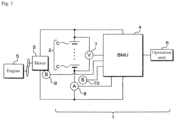
- Fig. 1 is an explanatory diagram schematically showing an electric configuration of a vehicle according to the first embodiment.
- the vehicle includes a vehicle control device 1, a motor (starter motor) 3, and an engine 5.
- the vehicle control device 1 includes a lead-acid battery (hereinafter, referred to as a battery) 2, a BMU (Battery Management Unit) 4, an operation unit 6, a voltage sensor 7, a current sensor 8, a first temperature sensor 9, and a second temperature sensor 10.
- a battery a lead-acid battery
- BMU Battery Management Unit
- operation unit 6 a voltage sensor 7, a current sensor 8, a first temperature sensor 9, and a second temperature sensor 10.
- the battery 2 has a plurality of cells C connected in series.
- the voltage sensor 7 is connected in parallel to the battery 2 and outputs a detection result according to the overall voltage value of the battery 2.
- the current sensor 8 is connected in series to the battery 2 and outputs a detection result according to the value of a current (charge-discharge current) flowing through the battery 2.
- the first temperature sensor 9 is disposed near the motor 3 and outputs a detection result according to the temperature of the motor 3.
- the second temperature sensor 10 is disposed near the battery 2 and outputs a detection result according to the temperature of the battery 2.
- Fig. 2 is a block diagram showing a configuration of the BMU 4.
- the BMU 4 includes a control unit 41, a storage unit 53, an input unit 56, and an interface unit 57. These units are communicably connected to each other via a bus.
- the input unit 56 receives input of detection results from the voltage sensor 7, the current sensor 8, the first temperature sensor 9, and the second temperature sensor 10.
- the interface unit 57 includes, for example, a LAN interface, a USB interface, and the like, and performs communication with another device such as the operation unit 6 by wire or wirelessly.
- the storage unit 53 is composed of, for example, a hard disk drive (HDD) and stores various programs and data.
- the storage unit 53 stores, for example, a restart determination program 54 for executing a restart determination process described later.
- the restart determination program 54 is provided in a state stored in a computer-readable recording medium (not shown) such as a CD-ROM, a DVD-ROM, and a USB memory, and is stored in the storage unit 53 by being installed in the BMU 4.
- the storage unit 53 stores map data 55.
- the map data 55 is data representing a no-load voltage value V 0 for each temperature and each SOC of the battery 2 during the idling stop, is obtained by an experiment in advance, is input to the BMU 4 via the interface unit 57, and is stored in the storage unit 53.
- the control unit 41 is configured by, for example, a CPU, a ROM, a RAM, and the like, and controls the operation of the BMU 4 by executing a computer program such as the restart determination program 54 read from the storage unit 53. For example, by reading and executing the restart determination program 54, the control unit 41 functions as a processing unit that executes a restart determination process described later.
- control unit 41 includes a first temperature acquisition unit 42, a second temperature acquisition unit 43, a voltage value acquisition unit 44, a current value acquisition unit 45, a V RESTmin calculation unit 46, an I ST (T ST ) calculation unit 47, a V 0 (T Batt , SOC) calculation unit 48, an Rss calculation unit 49, a V CR calculation unit 50, a determination unit 51, and a request unit 52.
- the functions of these units will be described later in the description of the restart determination process.
- Fig. 3 is a perspective view showing an external configuration of the battery 2
- Fig. 4 is a cross-sectional view taken along line IV-IV of Fig. 3 .
- the battery 2 includes a case 20, a positive electrode terminal 28, a negative electrode terminal 29, and a plurality of plate groups 23.
- the case 20 has a case body 201 and a cover plate 202.
- the case body 201 is a rectangular parallelepiped container with an upper portion opened, and is formed of, for example, a synthetic resin.
- the synthetic resin cover plate 202 closes an opening of the case body 201.
- the peripheral portion of the lower surface of the cover plate 202 and the peripheral portion of the opening of the case body 201 are joined by, for example, heat welding.
- the space in the case 20 is partitioned by a partition wall 27 into a plurality of cell chambers 21 arranged in the longitudinal direction of the case 20.
- Each cell chamber 21 in the case 20 contains an electrolytic solution 22 containing diluted sulfuric acid, and the entire plate group 23 is immersed in the electrolytic solution 22.
- the electrolytic solution 22 is injected into the cell chamber 21 from an electrolyte solution filling port (not shown) provided in the cover plate 202.
- the plate group 23 includes a plurality of positive electrode plates 231, a plurality of negative electrode plates 235, and a separator 239.
- the plurality of positive electrode plates 231 and the plurality of negative electrode plates 235 are arranged alternately.
- the positive electrode plate 231 includes a current collector 232 and an active material layer 234 supported by the current collector 232.
- the current collector 232 is a conductive member having a bone portion arranged substantially in a lattice or mesh shape, and is formed of, for example, lead or a lead alloy.
- the current collector 232 has a tab 233 protruding upward near the upper end.
- the active material layer 234 contains lead dioxide.
- the active material layer 234 may further contain a known additive.
- the negative electrode plate 235 includes a current collector 236 and an active material layer 238 supported by the current collector 236.
- the current collector 236 is a conductive member having a bone portion arranged substantially in a lattice or mesh shape, and is formed of, for example, lead or a lead alloy.
- the current collector 236 has a tab 237 protruding upward near the upper end.
- the active material layer 238 contains lead.
- the active material layer 238 may further contain a known additive.
- the separator 239 is formed of, for example, an insulating material such as glass and a synthetic resin.
- the separator 239 is interposed between the adjacent positive electrode plate 231 and negative electrode plate 235.
- the separator 239 may be configured as an integral member, or may be separately provided between the positive electrode plate 231 and the negative electrode plate 235.
- Tabs 233 of the plurality of positive electrode plates 231 are connected to a strap 24 formed of, for example, lead or a lead alloy. The plurality of positive electrode plates 231 are electrically connected in parallel via the strap 24.
- tabs 237 of the plurality of negative electrode plates 235 are connected to a strap 25 formed of, for example, lead or a lead alloy. The plurality of negative electrode plates 235 are electrically connected in parallel via the strap 25.
- a strap 25 in one cell chamber 21 is connected to a strap 24 in a first cell chamber 21 adjacent to the one cell chamber 21 via a connection member (bus bar) 26 formed of, for example, lead or a lead alloy. Further, a strap 24 in the one cell chamber 21 is connected via a connection member 26 to a strap 25 in a second cell chamber 21 adjacent to the one cell chamber 21. That is, the plurality of plate groups 23 of the battery 2 are electrically connected in series via the straps 24 and 25 and the connection member 26. As shown in Fig. 4 , the strap 24 housed in the cell chamber 21 located at one end in the direction in which the cells C are arranged is connected not to the connection member 26 but to a positive pole 282 described later. The strap 25 housed in the cell chamber 21 located at the other end in the direction in which the cells C are arranged is connected not to the connection member 26 but to a negative pole 292 (not shown).
- the positive electrode terminal 28 is disposed at one end in a direction in which the cells C are arranged, and the negative electrode terminal 29 is disposed near the other end in the direction.
- the positive electrode terminal 28 includes a bushing 281 and the positive pole 282.
- the bushing 281 is a substantially cylindrical conductive member, and is formed of, for example, a lead alloy.
- the lower portion of the bushing 281 is integrated with the cover plate 202 by insert molding, and the upper portion of the bushing 281 protrudes upward from the upper surface of the cover plate 202.
- the positive pole 282 is a substantially columnar conductive member, and is formed of, for example, a lead alloy.
- the positive pole 282 is inserted into a hole of the bushing 281.
- the upper end of the positive pole 282 is located at substantially the same position as the upper end of the bushing 281 and is joined to the bushing 281 by, for example, welding.
- the lower end of the positive pole 282 protrudes below the lower end of the bushing 281 and further protrudes below the lower surface of the cover plate 202, and is connected to the strap 24 housed in the cell chamber 21 located at one end in the direction in which the cells C are arranged.
- the negative electrode terminal 29 includes a bushing 291 and a negative pole 292 (see Fig. 3 ), and has the same configuration as the positive electrode terminal 28.
- a load (not shown) is connected to the bushing 281 of the positive electrode terminal 28 and the bushing 291 of the negative electrode terminal 29, and an electric power generated by a reaction on the positive electrode plate 231 (a reaction that generates lead sulfate from lead dioxide) and a reaction on the negative electrode plate 235 (a reaction that generates lead sulfate from lead (spongy lead)) of each plate group 23 is supplied to the load.
- a power supply (not shown) is connected to the bushing 281 of the positive electrode terminal 28 and the bushing 291 of the negative electrode terminal 29, and the power supplied from the power supply causes the reaction on the positive electrode plate 231 (a reaction that generates lead dioxide from lead sulfate) and the reaction on the negative electrode plate 235 (a reaction that generates lead (spongy lead) from lead sulfate) of each plate group 23 to occur, and the battery 2 is charged.
- the control unit 41 of the BMU 4 acquires a voltage value between the positive electrode terminal 28 and the negative electrode terminal 29 of the battery 2 and a value of a current flowing through the battery 2 during an idling stop for stopping idling of the engine 5, calculates an internal resistance value of the battery 2 during the idling stop based on the voltage value, the current value and the no-load voltage value, and determines whether or not a restart of the engine 5 is possible based on the internal resistance value and the operating voltage value at least required for restarting the engine 5 of the motor 3.
- the voltage value acquisition unit 44 acquires the voltage value (first voltage value) V BattSS between the positive electrode terminal 28 and the negative electrode terminal 29 of the battery 2 from the voltage sensor 7 during the idling stop.
- the current value acquisition unit 45 acquires the current value I EL from the current sensor 8 during the idling stop.
- the current value I EL is a current value of a load such as the control unit 41 that operates during the idling stop.
- the first temperature acquisition unit 42 acquires the temperature T ST of the motor 3 from the first temperature sensor 9.
- the second temperature acquisition unit 43 acquires the temperature T Batt of the battery 2 from the second temperature sensor 10.
- the V RESTmin calculation unit 46 calculates an operating voltage value V RESTmin required for restarting the engine 5 based on the configuration of the motor 3, the circuit, the starter relay, and the like.
- the I ST (T ST ) calculation unit 47 performs temperature compensation on the cranking current value I ST based on the temperature T ST of the motor 3 acquired from the first temperature acquisition unit 42, and calculates I ST (T ST ).
- the V 0 (T Batt , SOC) calculation unit 48 obtains the no-load voltage value V 0 (T Batt , SOC) with reference to the map data 55 stored in the storage unit 53.
- Table 1 below shows an example of the map data 55.
- SOC 0% 10% 20% 30% 40% 50% 60% 70% 80% 90% 100% Temperature 10°C 10.89 V 11.46 V 11.66 V 11.80 V 11.91 V 12.01 V 12.10 V 12.18 V 12.26 V 12.32 V 12.44 V 25°C 11.20 V 11.58 V 11.75 V 11.88 V 11.99 V 12.08 V 12.17 V 12.25 V 12.33 V 12.40 V 12.53 V 40°C 11.52 V 11.70 V 11.84 V 11.96 V 12.06 V 12.15 V 12.24 V 12.33 V 12.40 V 12.48 V 12.63 V
- V 0 (T Batt , SOC) calculation unit 48 calculates V 0 (T Batt , SOC) by performing linear interpolation.
- the Rss calculation unit 49 calculates the internal resistance value Rss by the following equation (1) using the no-load voltage value V 0 (T Batt , SOC), the temperature V BattSS , and the current value I EL .
- V 0 T Batt , SOC
- V BattSS V 0 T Batt SOC ⁇ V BattSS / I EL
- the V CR calculation unit 50 calculates an estimated voltage value (second voltage value) V CR when stopping the idling stop and operating the motor 3 by the following equation (2) using the no-load voltage value V 0 (T Batt , SOC), the internal resistance value Rss, the cranking current value I ST (T ST ), and the current value I EL .
- V CR V 0 T Batt SOC ⁇ R SS ⁇ I ST T ST + I EL
- the determination unit 51 compares the second voltage value V CR with the operating voltage value V RESTmin to determine whether a restart is possible. When V CR ⁇ V RESTmin , the determinatioon unit 51 determines that the restart is possible. When V CR ⁇ V RESTmin , the determination unit 51 determines that the restart is not possible.
- the request unit 52 stops the idling stop and requests the restart of the engine 5.
- Fig. 5 is a graph showing the relationship between the SOC and the internal resistance value for a battery that has been internally short-circuited and a normal battery.
- the horizontal axis represents SOC (%), and the vertical axis represents internal resistance value (mS2).
- a battery with an internal short-circuit is shown by a solid line, and a normal battery is shown by a broken line.
- Fig. 6 is a graph showing the relationship between the SOC and the internal resistance value for a battery that has been internally short-circuited and a normal battery.
- the horizontal axis represents SOC (%), and the vertical axis represents internal resistance value (mS2).
- a battery with an internal short-circuit is shown by a solid line, and a normal battery is shown by a broken line.
- Fig. 7 is an explanatory diagram showing a mechanism of the detection operation.
- the horizontal axis represents the current value (A), and the vertical axis represents the voltage value (V).
- the acquired voltage value at the time of measurement (1) during an idling stop in Fig. 7 is V BattSS , and the acquired current value is I EL .
- the internal resistance value Rss at this time is obtained by the above equation (1).
- the current value is made to correspond to the total value of I EL and I ST (T ST ) from I EL , and the second voltage value V CR when stopping the idling stop and operating the motor 3 is estimated.
- the internal resistance value Rss is larger than the internal resistance value Rss of (1)
- the second voltage value V CR is smaller than the second voltage value V CR of (1) and is equal to the operating voltage value V RESTmin at least required for restarting the engine 5. If the second voltage value V CR is smaller than the operating voltage value V RESTmin , the engine 5 cannot be restarted. In this case, the determination unit 51 determines that restart is not possible, and the request unit 52 stops idling stop and requests restart.
- the second voltage value V CR obtained from the straight line (2) is a lower limit voltage value for determining whether or not the restart is possible.
- the positive electrode current collector 232 shown in Fig. 4 extends upward and comes into contact with the negative electrode tab 237.
- the positive electrode current collector 232 shown in Fig. 4 extends upward and comes into contact with the negative electrode strap 25.
- the active material drops off from the active material layer 234 of the positive electrode plate 231, soars by the gas, and deposits on the tab 237 or the like of the negative electrode plate 235.
- Fig. 8 is a cross-sectional view showing a pair of the positive electrode plate 231 and the negative electrode plate 235 and the separator 239 of the cell of the battery 2 when no internal short-circuit occurs.
- Active material layers 234 and 238 are provided on both surfaces of the current collectors 232 and 236, respectively.
- the separator 239 is interposed between the opposing active material layers 234 and 238.
- Fig. 9 is a cross-sectional view showing a pair of the positive electrode plate 231 and the negative electrode plate 235 and the separator 239 of the cell of the battery 2 when a cell bottom short-circuit occurs.
- the separator 239 is deteriorated to form a hole, and the active material layer 234 of the positive electrode plate 231 projects to the active material layer 238 of the negative electrode plate 235, and conducts.
- Fig. 10 is a cross-sectional view showing a pair of the positive electrode plate 231 and the negative electrode plate 235 and the separator 239 of the cell of the battery 2 when the current collector 232 penetrates through the separator 239.
- the current collector 232 bends and penetrates through the separator 239.
- the current collector 236 bends and penetrates through the separator 239.
- Lead sulfate permeates the separator 239 from the active material layer 238 of the negative electrode plate 235, and lead sulfate accumulates inside the separator 239 and enters the active material layer 234 of the positive electrode plate 231 to cause a short circuit.
- Needle-like crystals permeate the separator 239 from the active material layer 238 of the negative electrode plate 235 and enter the active material layer 234 of the positive electrode plate 231 to cause a short circuit.
- a gap is generated due to the deterioration of the connection member 26, and the active material layer 234 and the active material layer 238 are short-circuited.
- a short circuit occurs when a metal piece is mixed to electrically connect the positive electrode and the negative electrode, or when the metal dissolves and precipitates on the electrode plate or adheres to the separator 239 and breaks through.
- Fig. 11 is a flowchart illustrating a processing procedure of the restart determination of the control unit 41.
- the determination unit 51 of the control unit 41 determines whether or not the state is an IG-ON (ignition-ON) state (S1).
- the determination unit 51 when having determined that the state is not the IG-ON state (S1: NO), ends the restart determination process.
- the determination unit 51 when having determined that the state is the IG-ON state (S1: YES), determines whether or not the vehicle is during an idling stop (S2).
- the determination unit 51 when having determined that the vehicle is not during the idling stop (S2: NO), returns the process to S1.
- the determination unit 51 when having determined that the vehicle is during the idling stop (S2: YES), acquires the first voltage value V BattSS by the voltage value acquisition unit 44, acquires the current value I EL by the current value acquisition unit 45, acquires the temperature T Batt by the second temperature acquisition unit 43, and acquires the temperature T ST by the first temperature acquisition unit 42. Then, the SOC is calculated based on the charge-discharge history stored in the storage unit 53 (S3).
- the determination unit 51 acquires the no-load voltage value V 0 (T Batt , SOC) by referring to the map data 55 based on the temperature T Batt and SOC acquired by the V 0 (T Batt , SOC) calculation unit 48 (S4).
- the determination unit 51 calculates the cranking current value I ST (T ST ) by the I ST (T ST ) calculation unit 47 (S5).
- the determination unit 51 calculates the internal resistance value Rss using the equation (1) by the Rss calculation unit 49 (S6).
- the determination unit 51 calculates the second voltage value V CR using the equation (2) by the V CR calculation unit 50 (S7).
- the determination unit 51 calculates the operating voltage value V RESTmin by the V RESTmin calculation unit 46 (S8).
- the determination unit 51 determines whether or not the second voltage value V CR is smaller than the operating voltage value V RESTmin (S9).
- the determination unit 51 when having determined that the second voltage value V CR is not smaller than the operating voltage value V RESTmin (S9: NO), returns the process to S2.
- the request unit 52 stops idling stop and requests a restart of the engine 5 (S 10).
- T Batt the temperature of the positive electrode terminal 28 or the negative electrode terminal 29 may be used.
- the liquid temperature estimated from the ambient temperature may be used. It may be calculated by the following equation (3).
- the water temperature of the engine 5 may be used.
- the operating voltage value V RESTmin or the second voltage value V CR is preferably provided with a margin in consideration of the amount of electric power for restart. Thereby, failure of restart can be further prevented.
- V CR 2 V 0 T Batt SOC ⁇ R SS + R WH + R ST + R CON ⁇ I ST T ST + I EL
- R WH Resistance value of wire
- the second voltage value V CR (2) of the motor 3 is estimated, and whether the restart is possible or not is compared with the lowest operating voltage value V RESTmin of the motor 3, so that the determination accuracy is further improved.
- the second voltage value V CR (3) of the battery 2 is calculated in consideration of the increase amount of the short-circuit current value due to the external short-circuit of the battery 2.
- the second voltage value V CR (3) is calculated by the following equation (5).
- V CR 3 V 0 T Batt SOC ⁇ R SS ⁇ I ST T ST + I EL + I OSC where Iosc: current value of external short-circuit
- the second voltage value V CR (4) of the motor 3 in consideration of the increase amount of the short-circuit current value and the decrease amount of the resistance value due to the external short-circuit of the battery 2 is used.
- the second voltage value V CR (4) is calculated by the following equation (6).
- V CR 4 V 0 T Batt SOC ⁇ R SS + R WH + R ST + R CON ⁇ R OSC ⁇ I ST T ST + I EL + I OSC where Rose: decrease amount in resistance value
- the control unit 41 functions as a processing unit that executes a process of determining the presence or absence of an internal short-circuit.
- the control unit 41 determines the presence or absence of an internal short-circuit based on the internal resistance value Rss calculated by the Rss calculation unit 49. If the internal resistance value Rss is equal to or greater than the threshold, it is determined that an internal short-circuit has occurred during an idling stop.
- the internal state (deterioration) of the battery 2 can be detected, it can be determined whether or not a restart of the engine 5 is possible. In addition, the occurrence of an internal short-circuit is notified in the operation unit 6, and measures such as charging or replacing the battery 2 can be taken.
- the vehicle was assumed to be a gasoline engine vehicle (1.5 L), and "S-95 (12V-60Ah) was used as the battery 2.
- the internal short-circuit of the battery 2 can be accurately detected by calculating the internal resistance value Rss during an idling stop. Based on the degree of internal short-circuit corresponding to the internal resistance value Rss and the operating voltage value V RESTmin of the motor 3, it is possible to accurately determine whether or not a restart of the engine 5 is possible when the idling stop is stopped. If it is determined that the restart of the engine 5 is impossible, it is possible to prevent the restart of the engine 5 from failing due to discharge failure by stopping the idling stop and requesting the restart of the engine 5.
- the present invention is not limited to the case where the present invention is applied to an in-vehicle secondary battery.
- the method is not limited to the case of determining whether or not the restart of the engine 5 is possible after detecting the internal short-circuit.
- the battery 2 is a lead-acid battery.
- the present invention is not limited to this, and a lithium ion battery or the like may be used.
- control unit 41 of the BMU 4 is the restart determination device of the present invention and the internal short-circuit determination device.
- the present invention is not limited to this, and the ECU (Electronic Control Unit) may function as a restart determination device and an internal short-circuit determination device, or a control unit provided in the battery 2 may function as these devices.
- the one provided in a server or the like external to the moving body may detect an internal short-circuit of the secondary battery provided in the moving body, and remotely manage the restart of the engine 5.
Landscapes
- Engineering & Computer Science (AREA)
- Chemical & Material Sciences (AREA)
- Manufacturing & Machinery (AREA)
- Chemical Kinetics & Catalysis (AREA)
- Electrochemistry (AREA)
- General Chemical & Material Sciences (AREA)
- Physics & Mathematics (AREA)
- General Physics & Mathematics (AREA)
- Power Engineering (AREA)
- Combustion & Propulsion (AREA)
- Mechanical Engineering (AREA)
- General Engineering & Computer Science (AREA)
- Health & Medical Sciences (AREA)
- General Health & Medical Sciences (AREA)
- Medical Informatics (AREA)
- Microelectronics & Electronic Packaging (AREA)
- Secondary Cells (AREA)
- Charge And Discharge Circuits For Batteries Or The Like (AREA)
- Control Of Vehicle Engines Or Engines For Specific Uses (AREA)
Description
- The present invention relates to a restart determination device that determines whether or not a restart of an engine is possible during an idling stop, an internal short-circuit determination device that determines whether or not an internal short-circuit has occurred in an energy storage device during an idling stop, a restart determination method, and a computer program for causing a computer to execute a restart determination process.
- For example, a secondary battery (energy storage device) such as a lead-acid battery is mounted on a moving body such as a vehicle, and is used as a power supply source for a starter motor when starting an engine and a power supply source for various electric components such as lights.
- When a vehicle is stopped, such as when waiting for a traffic light, for the purpose of suppressing energy consumption and noise, a control called idling stop for temporarily stopping an engine, restarting the engine when the stop condition of the vehicle is canceled, such as when a traffic light changes, and restarting traveling is performed.
- If the battery short-circuits internally during an idling stop, the internal resistance increases despite the small amount of discharge, so the battery discharge voltage value after stopping the idling stop becomes low, and the engine may not be able to restart.
- Therefore, it is necessary to detect the internal state (deterioration state) of the battery.
- The deterioration state determination device of
Patent Document 1 estimates an equivalent series resistance of an auxiliary battery based on a detected value of a voltage between terminals of the auxiliary battery and a detected value of a current flowing through the auxiliary battery during a period in which power is supplied from the auxiliary battery. The equivalent series resistance is corrected based on SOC of the auxiliary battery and a detected temperature value of the auxiliary battery. The deterioration state of the auxiliary battery is determined based on the corrected equivalent series resistance.Patent Document 2 describes a specific battery detection means that specifies single batteries believed to be in an excess discharge state during operation of the electric motor for starting the engine. -
- Patent Document 1:
JP-A-2016-114584 - Patent Document 2:
US 2007/0013347 A1 - In the deterioration state determination device of
Patent Document 1, the internal state of the battery is detected during traveling. The battery used is a battery for hybrid vehicles, which is used at around 50% SOC, and can detect the internal state in both cases of charging and discharging. - In the case of a lead-acid battery, it is used on the high SOC side, and the internal resistance value during charging and the internal resistance value during discharging do not have a linear relationship. Therefore, it is not possible to detect a short circuit by applying the internal state determination method of
Patent Document 1 and accurately determine whether or not a restart of the engine is possible. - The present invention has an object to provide a restart determination device that can determine whether or not a restart is possible during an idling stop and can prevent restart failure due to inability to discharge, an internal short-circuit determination device that can determine the presence or absence of an internal short-circuit during the idling stop, a restart determination method, and a computer program.
- The scope of the present invention is defined by the independent claims. A restart determination device according to the present invention includes a voltage value acquisition unit that acquires a first voltage value between terminals of an energy storage device during an idling stop for stopping idling of an engine, a current value acquisition unit that acquires a value of a current flowing through the energy storage device during the idling stop, a calculation unit that calculates an internal resistance value of the energy storage device during the idling stop, based on the first voltage value, the current value, and a no-load voltage value, and a determination unit that determines whether or not a restart of the engine is possible based on the internal resistance value and an operating voltage value of a starter motor of the engine.
- According to the present invention, since the internal resistance value of the energy storage device during the idling stop is calculated based on the first voltage value, the current value, and the no-load voltage value, internal short-circuit of the energy storage device can be accurately detected during the idling stop. It is possible to accurately determine whether or not a restart of the engine is possible when idling stop is stopped, based on the degree of internal short-circuit corresponding to the internal resistance value and the operating voltage value of the starter motor.
-
-
Fig. 1 is an explanatory view schematically showing an electric configuration of a vehicle according to a first embodiment. -
Fig. 2 is a block diagram showing a configuration of a BMU. -
Fig. 3 is a perspective view showing an external configuration of a battery. -
Fig. 4 is a cross-sectional view taken along line IV-IV ofFig. 3 . -
Fig. 5 is a graph showing the relationship between the SOC and the internal resistance value of a battery having an internal short-circuit and a normal battery. -
Fig. 6 is a graph showing the relationship between the SOC and the internal resistance value of a battery having an internal short-circuit and a normal battery. -
Fig. 7 is an explanatory diagram showing a mechanism of a detection operation. -
Fig. 8 is a cross-sectional view showing a pair of a positive electrode plate and a negative electrode plate, and a separator of a battery cell when no internal short-circuit occurs. -
Fig. 9 is a cross-sectional view showing a pair of a positive electrode plate and a negative electrode plate, and a separator of a battery cell when a lower cell short-circuit occurs. -
Fig. 10 is a cross-sectional view showing a pair of a positive electrode plate and a negative electrode plate, and a separator of a battery cell when a current collector passes through the separator. -
Fig. 11 is a flowchart showing a processing procedure of a restart determination of a control unit. - A restart determination device according to the present embodiment includes a voltage value acquisition unit that acquires a first voltage value between terminals of an energy storage device during an idling stop for stopping idling of an engine, a current value acquisition unit that acquires a value of a current flowing through the energy storage device during the idling stop, a calculation unit that calculates an internal resistance value of the energy storage device during the idling stop, based on the first voltage value, the current value, and a no-load voltage value, and a determination unit that determines whether or not a restart of the engine is possible based on the internal resistance value and an operating voltage value of a starter motor of the engine.
- When an internal short-circuit occurs in the energy storage device during the idling stop, the internal resistance value increases. According to the above configuration, since the internal resistance value of the energy storage device during the idling stop is calculated based on the first voltage value, the current value, and the no-load voltage value, internal short-circuit of the energy storage device can be accurately detected during the idling stop. It is possible to accurately determine whether or not a restart of the engine is possible when idling stop is stopped, based on the degree of internal short-circuit corresponding to the internal resistance value and the operating voltage value of the starter motor.
- Even when the energy storage device discharges on the high SOC side, the internal resistance value can be calculated accurately, and the internal short-circuit of a lead-acid battery or the like can be detected accurately.
- The above-described restart determination device includes an estimation unit that estimates a second voltage value of the energy storage device when the idling stop is stopped and the engine is restarted, based on the no-load voltage value, the internal resistance value, the current value, and a cranking current value, and the determination unit makes a determination based on the second voltage value and the operating voltage value.
- Since the second voltage value of the energy storage device when the engine is restarted is estimated, based on the no-load voltage value, the current value when the engine is restarted (the sum of the current value and the cranking current value), and the internal resistance value, the accuracy of the estimation is high. By comparing the operating voltage value with the second voltage value, it is possible to accurately determine whether or not a restart of the engine is possible.
- In the above-described restart determination device, the calculation unit may calculate the internal resistance value by dividing a difference between the no-load voltage value and the first voltage value by the current value.
- The difference between the no-load voltage value and the first voltage value corresponds to the amount of decrease in the voltage value due to the internal short-circuit, and by dividing this by the current value, the internal resistance value due to the internal short-circuit can be favorably calculated.
- The above-described restart determination device may include a request unit that stops the idling stop and requests a restart when the determination unit determines that the restart is not possible.
- Since the idling stop is stopped and the restart is requested before the discharge voltage value decreases and becomes lower than the operating voltage value, the restart failure due to inability to discharge is successfully prevented.
- The above-described restart determination device may include a storage unit that stores a map representing the no-load voltage value for each temperature and each SOC of the energy storage device during the idling stop, and the calculation unit may refer to the map and acquire the no-load voltage value.
- By compensating for the temperature and the SOC, the no-load voltage value becomes more accurate, and the accuracy of the determination is further improved.
- The internal short-circuit determination device according to the present embodiment includes a voltage value acquisition unit that acquires a voltage value between terminals of the energy storage device during an idling stop for stopping idling of the engine, a current value acquisition unit that acquires a value of a current flowing through the energy storage device during the idling stop, a calculation unit that calculates an internal resistance value of the energy storage device during the idling stop based on the voltage value, the current value, and a no-load voltage value, and a determination unit that determines the presence or absence of an internal short-circuit in the energy storage device based on the internal resistance value.
- As described above, when an internal short-circuit occurs in the energy storage device during the idling stop, since the internal resistance value increases, it is possible to determine the presence or absence of the internal short-circuit in the energy storage device, based on the internal resistance value. Since the internal state (deterioration) of the energy storage device can be detected, it is possible to determine whether or not a restart is possible and to take a measure such as charging or replacing the energy storage device.
- The restart determination method according to the present embodiment includes, acquiring a voltage value between terminals of an energy storage device and a value of a current flowing through the energy storage device during an idling stop for stopping idling of an engine, calculating an internal resistance value of the energy storage device during the idling stop, based on the voltage value, the current value, and a no-load voltage value, and determining whether or not a restart of the engine is possible, based on the internal resistance value and an operating voltage value of a starter motor of the engine.
- According to the above configuration, since the internal resistance value of the energy storage device during the idling stop is calculated based on the first voltage value, the current value, and the no-load voltage value, internal short-circuit of the energy storage device can be accurately detected during the idling stop. Therefore, it is possible to accurately determine whether or not a restart of the engine is possible when the idling stop is stopped, based on the degree of the internal short-circuit corresponding to the internal resistance value and the operating voltage value of the starter motor.
- The computer program according to the present embodiment causes a computer to execute a process of, acquiring a voltage value between terminals of an energy storage device and a value of a current flowing through the energy storage device during an idling stop for stopping idling of an engine, calculating an internal resistance value of the energy storage device during the idling stop, based on the voltage value, the current value, and a no-load voltage value, and determining whether or not a restart of the engine is possible, based on the internal resistance value and an operating voltage value of a starter motor of the engine.
- According to the above configuration, since the internal resistance value of the energy storage device during the idling stop is calculated based on the first voltage value, the current value, and the no-load voltage value, internal short-circuit of the energy storage device can be accurately detected during the idling stop. Therefore, it is possible to accurately determine whether or not a restart of the engine is possible when the idling stop is stopped, based on the degree of the internal short-circuit corresponding to the internal resistance value and the operating voltage value of the starter motor.
-
Fig. 1 is an explanatory diagram schematically showing an electric configuration of a vehicle according to the first embodiment. - The vehicle includes a
vehicle control device 1, a motor (starter motor) 3, and anengine 5. - The
vehicle control device 1 includes a lead-acid battery (hereinafter, referred to as a battery) 2, a BMU (Battery Management Unit) 4, anoperation unit 6, avoltage sensor 7, acurrent sensor 8, afirst temperature sensor 9, and asecond temperature sensor 10. - The
battery 2 has a plurality of cells C connected in series. - The
voltage sensor 7 is connected in parallel to thebattery 2 and outputs a detection result according to the overall voltage value of thebattery 2. Thecurrent sensor 8 is connected in series to thebattery 2 and outputs a detection result according to the value of a current (charge-discharge current) flowing through thebattery 2. Thefirst temperature sensor 9 is disposed near the motor 3 and outputs a detection result according to the temperature of the motor 3. Thesecond temperature sensor 10 is disposed near thebattery 2 and outputs a detection result according to the temperature of thebattery 2. -
Fig. 2 is a block diagram showing a configuration of theBMU 4. TheBMU 4 includes acontrol unit 41, astorage unit 53, aninput unit 56, and aninterface unit 57. These units are communicably connected to each other via a bus. - The
input unit 56 receives input of detection results from thevoltage sensor 7, thecurrent sensor 8, thefirst temperature sensor 9, and thesecond temperature sensor 10. Theinterface unit 57 includes, for example, a LAN interface, a USB interface, and the like, and performs communication with another device such as theoperation unit 6 by wire or wirelessly. - The
storage unit 53 is composed of, for example, a hard disk drive (HDD) and stores various programs and data. Thestorage unit 53 stores, for example, arestart determination program 54 for executing a restart determination process described later. Therestart determination program 54 is provided in a state stored in a computer-readable recording medium (not shown) such as a CD-ROM, a DVD-ROM, and a USB memory, and is stored in thestorage unit 53 by being installed in theBMU 4. In addition, thestorage unit 53 stores mapdata 55. Themap data 55 is data representing a no-load voltage value V0 for each temperature and each SOC of thebattery 2 during the idling stop, is obtained by an experiment in advance, is input to theBMU 4 via theinterface unit 57, and is stored in thestorage unit 53. - The
control unit 41 is configured by, for example, a CPU, a ROM, a RAM, and the like, and controls the operation of theBMU 4 by executing a computer program such as therestart determination program 54 read from thestorage unit 53. For example, by reading and executing therestart determination program 54, thecontrol unit 41 functions as a processing unit that executes a restart determination process described later. - Specifically, the
control unit 41 includes a firsttemperature acquisition unit 42, a secondtemperature acquisition unit 43, a voltagevalue acquisition unit 44, a current value acquisition unit 45, a VRESTmin calculation unit 46, an IST (TST)calculation unit 47, a V0 (TBatt, SOC)calculation unit 48, anRss calculation unit 49, a VCR calculation unit 50, adetermination unit 51, and arequest unit 52. The functions of these units will be described later in the description of the restart determination process. -
Fig. 3 is a perspective view showing an external configuration of thebattery 2, andFig. 4 is a cross-sectional view taken along line IV-IV ofFig. 3 . - As shown in
Figs. 3 and4 , thebattery 2 includes acase 20, apositive electrode terminal 28, anegative electrode terminal 29, and a plurality ofplate groups 23. - The
case 20 has acase body 201 and acover plate 202. Thecase body 201 is a rectangular parallelepiped container with an upper portion opened, and is formed of, for example, a synthetic resin. For example, the syntheticresin cover plate 202 closes an opening of thecase body 201. The peripheral portion of the lower surface of thecover plate 202 and the peripheral portion of the opening of thecase body 201 are joined by, for example, heat welding. The space in thecase 20 is partitioned by apartition wall 27 into a plurality ofcell chambers 21 arranged in the longitudinal direction of thecase 20. - One
plate group 23 is housed in eachcell chamber 21 in thecase 20. Eachcell chamber 21 in thecase 20 contains anelectrolytic solution 22 containing diluted sulfuric acid, and theentire plate group 23 is immersed in theelectrolytic solution 22. Theelectrolytic solution 22 is injected into thecell chamber 21 from an electrolyte solution filling port (not shown) provided in thecover plate 202. - The
plate group 23 includes a plurality ofpositive electrode plates 231, a plurality ofnegative electrode plates 235, and aseparator 239. The plurality ofpositive electrode plates 231 and the plurality ofnegative electrode plates 235 are arranged alternately. - The
positive electrode plate 231 includes acurrent collector 232 and anactive material layer 234 supported by thecurrent collector 232. Thecurrent collector 232 is a conductive member having a bone portion arranged substantially in a lattice or mesh shape, and is formed of, for example, lead or a lead alloy. Thecurrent collector 232 has atab 233 protruding upward near the upper end. Theactive material layer 234 contains lead dioxide. Theactive material layer 234 may further contain a known additive. - The
negative electrode plate 235 includes acurrent collector 236 and anactive material layer 238 supported by thecurrent collector 236. Thecurrent collector 236 is a conductive member having a bone portion arranged substantially in a lattice or mesh shape, and is formed of, for example, lead or a lead alloy. Thecurrent collector 236 has atab 237 protruding upward near the upper end. Theactive material layer 238 contains lead. Theactive material layer 238 may further contain a known additive. - The
separator 239 is formed of, for example, an insulating material such as glass and a synthetic resin. Theseparator 239 is interposed between the adjacentpositive electrode plate 231 andnegative electrode plate 235. Theseparator 239 may be configured as an integral member, or may be separately provided between thepositive electrode plate 231 and thenegative electrode plate 235. -
Tabs 233 of the plurality ofpositive electrode plates 231 are connected to astrap 24 formed of, for example, lead or a lead alloy. The plurality ofpositive electrode plates 231 are electrically connected in parallel via thestrap 24. Similarly,tabs 237 of the plurality ofnegative electrode plates 235 are connected to astrap 25 formed of, for example, lead or a lead alloy. The plurality ofnegative electrode plates 235 are electrically connected in parallel via thestrap 25. - In the
battery 2, astrap 25 in onecell chamber 21 is connected to astrap 24 in afirst cell chamber 21 adjacent to the onecell chamber 21 via a connection member (bus bar) 26 formed of, for example, lead or a lead alloy. Further, astrap 24 in the onecell chamber 21 is connected via aconnection member 26 to astrap 25 in asecond cell chamber 21 adjacent to the onecell chamber 21. That is, the plurality ofplate groups 23 of thebattery 2 are electrically connected in series via thestraps connection member 26. As shown inFig. 4 , thestrap 24 housed in thecell chamber 21 located at one end in the direction in which the cells C are arranged is connected not to theconnection member 26 but to apositive pole 282 described later. Thestrap 25 housed in thecell chamber 21 located at the other end in the direction in which the cells C are arranged is connected not to theconnection member 26 but to a negative pole 292 (not shown). - The
positive electrode terminal 28 is disposed at one end in a direction in which the cells C are arranged, and thenegative electrode terminal 29 is disposed near the other end in the direction. - As shown in
Fig. 4 , thepositive electrode terminal 28 includes abushing 281 and thepositive pole 282. Thebushing 281 is a substantially cylindrical conductive member, and is formed of, for example, a lead alloy. The lower portion of thebushing 281 is integrated with thecover plate 202 by insert molding, and the upper portion of thebushing 281 protrudes upward from the upper surface of thecover plate 202. Thepositive pole 282 is a substantially columnar conductive member, and is formed of, for example, a lead alloy. Thepositive pole 282 is inserted into a hole of thebushing 281. The upper end of thepositive pole 282 is located at substantially the same position as the upper end of thebushing 281 and is joined to thebushing 281 by, for example, welding. The lower end of thepositive pole 282 protrudes below the lower end of thebushing 281 and further protrudes below the lower surface of thecover plate 202, and is connected to thestrap 24 housed in thecell chamber 21 located at one end in the direction in which the cells C are arranged. - Similarly to the
positive electrode terminal 28, thenegative electrode terminal 29 includes abushing 291 and a negative pole 292 (seeFig. 3 ), and has the same configuration as thepositive electrode terminal 28. - When the
battery 2 is discharged, a load (not shown) is connected to thebushing 281 of thepositive electrode terminal 28 and thebushing 291 of thenegative electrode terminal 29, and an electric power generated by a reaction on the positive electrode plate 231 (a reaction that generates lead sulfate from lead dioxide) and a reaction on the negative electrode plate 235 (a reaction that generates lead sulfate from lead (spongy lead)) of eachplate group 23 is supplied to the load. Further, when thebattery 2 is charged, a power supply (not shown) is connected to thebushing 281 of thepositive electrode terminal 28 and thebushing 291 of thenegative electrode terminal 29, and the power supplied from the power supply causes the reaction on the positive electrode plate 231 (a reaction that generates lead dioxide from lead sulfate) and the reaction on the negative electrode plate 235 (a reaction that generates lead (spongy lead) from lead sulfate) of eachplate group 23 to occur, and thebattery 2 is charged. - Hereinafter, the restart determination process according to the present embodiment will be described in detail.
- The
control unit 41 of theBMU 4 acquires a voltage value between thepositive electrode terminal 28 and thenegative electrode terminal 29 of thebattery 2 and a value of a current flowing through thebattery 2 during an idling stop for stopping idling of theengine 5, calculates an internal resistance value of thebattery 2 during the idling stop based on the voltage value, the current value and the no-load voltage value, and determines whether or not a restart of theengine 5 is possible based on the internal resistance value and the operating voltage value at least required for restarting theengine 5 of the motor 3. - That is, the voltage
value acquisition unit 44 acquires the voltage value (first voltage value) VBattSS between thepositive electrode terminal 28 and thenegative electrode terminal 29 of thebattery 2 from thevoltage sensor 7 during the idling stop. - The current value acquisition unit 45 acquires the current value IEL from the
current sensor 8 during the idling stop. The current value IEL is a current value of a load such as thecontrol unit 41 that operates during the idling stop. - The first
temperature acquisition unit 42 acquires the temperature TST of the motor 3 from thefirst temperature sensor 9. - The second
temperature acquisition unit 43 acquires the temperature TBatt of thebattery 2 from thesecond temperature sensor 10. - The VRESTmin calculation unit 46 calculates an operating voltage value VRESTmin required for restarting the
engine 5 based on the configuration of the motor 3, the circuit, the starter relay, and the like. - The IST (TST)
calculation unit 47 performs temperature compensation on the cranking current value IST based on the temperature TST of the motor 3 acquired from the firsttemperature acquisition unit 42, and calculates IST (TST). - The V0(TBatt, SOC)
calculation unit 48 obtains the no-load voltage value V0(TBatt, SOC) with reference to themap data 55 stored in thestorage unit 53. - Table 1 below shows an example of the
map data 55.[Table 1] SOC 0% 10% 20% 30% 40% 50% 60% 70% 80% 90% 100 % Temperature 10°C 10.89 V 11.46 V 11.66 V 11.80 V 11.91 V 12.01 V 12.10 V 12.18 V 12.26 V 12.32 V 12.44 V 25°C 11.20 V 11.58 V 11.75 V 11.88 V 11.99 V 12.08 V 12.17 V 12.25 V 12.33 V 12.40 V 12.53 V 40°C 11.52 V 11.70 V 11.84 V 11.96 V 12.06 V 12.15 V 12.24 V 12.33 V 12.40 V 12.48 V 12.63 V - When the numerical value of the temperature TBatt or SOC is between the numerical values of the temperature or SOC in the
map data 55, the V0(TBatt, SOC)calculation unit 48 calculates V0(TBatt, SOC) by performing linear interpolation. - The
Rss calculation unit 49 calculates the internal resistance value Rss by the following equation (1) using the no-load voltage value V0(TBatt, SOC), the temperature VBattSS, and the current value IEL.
- The VCR calculation unit 50 calculates an estimated voltage value (second voltage value) VCR when stopping the idling stop and operating the motor 3 by the following equation (2) using the no-load voltage value V0(TBatt, SOC), the internal resistance value Rss, the cranking current value IST (TST), and the current value IEL.

- The
determination unit 51 compares the second voltage value VCR with the operating voltage value VRESTmin to determine whether a restart is possible. When VCR ≥ VRESTmin, thedeterminatioon unit 51 determines that the restart is possible. When VCR < VRESTmin, thedetermination unit 51 determines that the restart is not possible. - If the
determination unit 51 determines that the restart is not possible, therequest unit 52 stops the idling stop and requests the restart of theengine 5. -
Fig. 5 is a graph showing the relationship between the SOC and the internal resistance value for a battery that has been internally short-circuited and a normal battery. The horizontal axis represents SOC (%), and the vertical axis represents internal resistance value (mS2). The battery short-circuited internally at 70% SOC. In the drawing, a battery with an internal short-circuit is shown by a solid line, and a normal battery is shown by a broken line. - From
Fig. 5 , it can be seen that the internal resistance value sharply increases due to the internal short-circuit despite the small amount of discharge. -
Fig. 6 is a graph showing the relationship between the SOC and the internal resistance value for a battery that has been internally short-circuited and a normal battery. The horizontal axis represents SOC (%), and the vertical axis represents internal resistance value (mS2). In the drawing, a battery with an internal short-circuit is shown by a solid line, and a normal battery is shown by a broken line. - In
Fig. 6 , when the internal resistance value was 5 mΩ before the start of the idling stop, the internal resistance value increased due to an internal short-circuit during the idling stop, and increased to 15 mΩ after the stop of the idling stop. -
Fig. 7 is an explanatory diagram showing a mechanism of the detection operation. The horizontal axis represents the current value (A), and the vertical axis represents the voltage value (V). - The acquired voltage value at the time of measurement (1) during an idling stop in
Fig. 7 is VBattSS, and the acquired current value is IEL. The internal resistance value Rss at this time is obtained by the above equation (1). In this internal resistance value Rss, the current value is made to correspond to the total value of IEL and IST(TST) from IEL, and the second voltage value VCR when stopping the idling stop and operating the motor 3 is estimated. - In the case of a straight line (2), the internal resistance value Rss is larger than the internal resistance value Rss of (1), and the second voltage value VCR is smaller than the second voltage value VCR of (1) and is equal to the operating voltage value VRESTmin at least required for restarting the
engine 5. If the second voltage value VCR is smaller than the operating voltage value VRESTmin, theengine 5 cannot be restarted. In this case, thedetermination unit 51 determines that restart is not possible, and therequest unit 52 stops idling stop and requests restart. - Thereby, when the restart is requested after the idling stop is continued, it is prevented that the discharge cannot be performed and the restart fails.
- That is, the second voltage value VCR obtained from the straight line (2) is a lower limit voltage value for determining whether or not the restart is possible.
- Hereinafter, the types of internal short-circuits will be described.
- In this case, the positive electrode
current collector 232 shown inFig. 4 extends upward and comes into contact with thenegative electrode tab 237. - In this case, the positive electrode
current collector 232 shown inFig. 4 extends upward and comes into contact with thenegative electrode strap 25. - In this case, the active material drops off from the
active material layer 234 of thepositive electrode plate 231, soars by the gas, and deposits on thetab 237 or the like of thenegative electrode plate 235. -
Fig. 8 is a cross-sectional view showing a pair of thepositive electrode plate 231 and thenegative electrode plate 235 and theseparator 239 of the cell of thebattery 2 when no internal short-circuit occurs. - Active material layers 234 and 238 are provided on both surfaces of the
current collectors separator 239 is interposed between the opposing active material layers 234 and 238. -
Fig. 9 is a cross-sectional view showing a pair of thepositive electrode plate 231 and thenegative electrode plate 235 and theseparator 239 of the cell of thebattery 2 when a cell bottom short-circuit occurs. - As shown in
Fig. 9 , theseparator 239 is deteriorated to form a hole, and theactive material layer 234 of thepositive electrode plate 231 projects to theactive material layer 238 of thenegative electrode plate 235, and conducts. -
Fig. 10 is a cross-sectional view showing a pair of thepositive electrode plate 231 and thenegative electrode plate 235 and theseparator 239 of the cell of thebattery 2 when thecurrent collector 232 penetrates through theseparator 239. - The
current collector 232 bends and penetrates through theseparator 239. - Contrary to (5), the
current collector 236 bends and penetrates through theseparator 239. - Lead sulfate permeates the
separator 239 from theactive material layer 238 of thenegative electrode plate 235, and lead sulfate accumulates inside theseparator 239 and enters theactive material layer 234 of thepositive electrode plate 231 to cause a short circuit. - Needle-like crystals (dendrites) permeate the
separator 239 from theactive material layer 238 of thenegative electrode plate 235 and enter theactive material layer 234 of thepositive electrode plate 231 to cause a short circuit. - A gap is generated due to the deterioration of the
connection member 26, and theactive material layer 234 and theactive material layer 238 are short-circuited. - A short circuit occurs when a metal piece is mixed to electrically connect the positive electrode and the negative electrode, or when the metal dissolves and precipitates on the electrode plate or adheres to the
separator 239 and breaks through. - Hereinafter, the restart determination process will be described as a process of the
control unit 41. -
Fig. 11 is a flowchart illustrating a processing procedure of the restart determination of thecontrol unit 41. - The
determination unit 51 of thecontrol unit 41 determines whether or not the state is an IG-ON (ignition-ON) state (S1). - The
determination unit 51, when having determined that the state is not the IG-ON state (S1: NO), ends the restart determination process. - The
determination unit 51, when having determined that the state is the IG-ON state (S1: YES), determines whether or not the vehicle is during an idling stop (S2). - The
determination unit 51, when having determined that the vehicle is not during the idling stop (S2: NO), returns the process to S1. - The
determination unit 51, when having determined that the vehicle is during the idling stop (S2: YES), acquires the first voltage value VBattSS by the voltagevalue acquisition unit 44, acquires the current value IEL by the current value acquisition unit 45, acquires the temperature TBatt by the secondtemperature acquisition unit 43, and acquires the temperature TST by the firsttemperature acquisition unit 42. Then, the SOC is calculated based on the charge-discharge history stored in the storage unit 53 (S3). - The
determination unit 51 acquires the no-load voltage value V0(TBatt, SOC) by referring to themap data 55 based on the temperature TBatt and SOC acquired by the V0(TBatt, SOC) calculation unit 48 (S4). - The
determination unit 51 calculates the cranking current value IST(TST) by the IST(TST) calculation unit 47 (S5). - The
determination unit 51 calculates the internal resistance value Rss using the equation (1) by the Rss calculation unit 49 (S6). - The
determination unit 51 calculates the second voltage value VCR using the equation (2) by the VCR calculation unit 50 (S7). - The
determination unit 51 calculates the operating voltage value VRESTmin by the VRESTmin calculation unit 46 (S8). - The
determination unit 51 determines whether or not the second voltage value VCR is smaller than the operating voltage value VRESTmin (S9). - The
determination unit 51, when having determined that the second voltage value VCR is not smaller than the operating voltage value VRESTmin (S9: NO), returns the process to S2. - When the
determination unit 51 determines that the second voltage value VCR is smaller than the operating voltage value VRESTmin (S9: YES), therequest unit 52 stops idling stop and requests a restart of the engine 5 (S 10). - As the temperature TBatt, the temperature of the
positive electrode terminal 28 or thenegative electrode terminal 29 may be used. Alternatively, the liquid temperature estimated from the ambient temperature may be used. It may be calculated by the following equation (3).
- As the temperature TST, the water temperature of the
engine 5 may be used. - The operating voltage value VRESTmin or the second voltage value VCR is preferably provided with a margin in consideration of the amount of electric power for restart. Thereby, failure of restart can be further prevented.
- Instead of the second voltage value VCR of the
battery 2, the second voltage value VCR(2) of the motor 3 when theengine 5 is restarted is used. The second voltage value VCR(2) of the motor 3 is calculated by the following equation (4).
- RST: Resistance value of Motor 3
- RCON: Contact resistance value
- According to the first modification, the second voltage value VCR(2) of the motor 3 is estimated, and whether the restart is possible or not is compared with the lowest operating voltage value VRESTmin of the motor 3, so that the determination accuracy is further improved.
- The second voltage value VCR(3) of the
battery 2 is calculated in consideration of the increase amount of the short-circuit current value due to the external short-circuit of thebattery 2. The second voltage value VCR(3) is calculated by the following equation (5).
- The second voltage value VCR(4) of the motor 3 in consideration of the increase amount of the short-circuit current value and the decrease amount of the resistance value due to the external short-circuit of the
battery 2 is used. The second voltage value VCR(4) is calculated by the following equation (6).
- The
control unit 41 functions as a processing unit that executes a process of determining the presence or absence of an internal short-circuit. - The
control unit 41 determines the presence or absence of an internal short-circuit based on the internal resistance value Rss calculated by theRss calculation unit 49. If the internal resistance value Rss is equal to or greater than the threshold, it is determined that an internal short-circuit has occurred during an idling stop. - Since the internal state (deterioration) of the
battery 2 can be detected, it can be determined whether or not a restart of theengine 5 is possible. In addition, the occurrence of an internal short-circuit is notified in theoperation unit 6, and measures such as charging or replacing thebattery 2 can be taken. - The following evaluation test was performed to verify the restart determination process of the present embodiment.
- The vehicle was assumed to be a gasoline engine vehicle (1.5 L), and "S-95 (12V-60Ah) was used as the
battery 2. - In the case where an internal short-circuit of the above-described classifications (1) to (10) was made to occur in the
battery 2, the second voltage value VCR was calculated using the above equation (2), the voltage value was measured, and the error was obtained. The results are shown in Table 2 below. The operating voltage value VRESTmin is 3.5 V and IST(TST) is 250 A.[Table 2] Classification VCR Measured voltage Error Start limit Detection determination (1) 4.11 V 4.99 V 0.88 V > 3.5 V ○ 4.52 V 4.06 V 0.46 V > 3.5 V ○ 4.59 V 5.00 V 0.41 V > 3.5 V ○ (2) 5.52 V 5.10 V 0.42 V > 3.5 V ○ 5.07 V 5.56 V 0.49 V > 3.5 V ○ 5.86 V 5.40 V 0.46 V > 3.5 V ○ (3) 5.87 V 5.92 V 0.05 V > 3.5 V ○ 5.25 V 5.63 V 0.38 V > 3.5 V ○ 5.41 V 5.24 V 0.17 V > 3.5 V ○ (4) 5.11 V 5.91 V 0.80 V > 3.5 V ○ 5.03 V 5.73 V 0.70 V > 3.5 V ○ 5.48 V 5.60 V 0.12 V > 3.5 V ○ (5) 4.26 V 4.63 V 0.37 V > 3.5 V ○ 5.11 V 5.22 V 0.11 V > 3.5 V ○ 5.03 V 5.81 V 0.78 V > 3.5 V ○ (6) 5.88 V 5.63 V 0.25 V > 3.5 V ○ 5.94 V 5.66 V 0.28 V > 3.5 V ○ 5.04 V 5.54 V 0.50 V > 3.5 V ○ (7) 4.65 V 4.10 V 0.55 V > 3.5 V ○ 5.14 V 5.12 V 0.02 V > 3.5 V ○ 5.13 V 5.24 V 0.11 V > 3.5 V ○ (8) 5.28 V 5.65 V 0.37 V > 3.5 V ○ 5.32 V 5.55 V 0.23 V > 3.5 V ○ 5.50 V 5.91V 0.41 V > 3.5 V ○ (9) 4.15 V 4.92 V 0.77 V > 3.5 V ○ 5.64 V 5.32 V 0.32 V > 3.5 V ○ 5.16 V 5.38 V 0.22 V > 3.5 V ○ (10) 4.88 V 4.52 V 0.36 V > 3.5 V ○ 4.90 V 4.51 V 0.39 V > 3.5 V ○ 4.57 V 4.91V 0.34 V > 3.5 V ○ Standard deviation 0.23 V - From Table 2, it was confirmed that no matter which internal short-circuit occurred, the occurrence of the internal short-circuit was able to be detected and it was able to be determined whether a restart was possible. The standard deviation of the error between the second voltage value VCR and the measured voltage value is 0.23 V, and the calculation accuracy of the second voltage value VCR is good.
- As described above, in the present embodiment, the internal short-circuit of the
battery 2 can be accurately detected by calculating the internal resistance value Rss during an idling stop. Based on the degree of internal short-circuit corresponding to the internal resistance value Rss and the operating voltage value VRESTmin of the motor 3, it is possible to accurately determine whether or not a restart of theengine 5 is possible when the idling stop is stopped. If it is determined that the restart of theengine 5 is impossible, it is possible to prevent the restart of theengine 5 from failing due to discharge failure by stopping the idling stop and requesting the restart of theengine 5. - When the second voltage value VCR of the
battery 2 when restarting theengine 5 is estimated based on the no-load voltage value V0(TBatt, SOC), the current value when restarting the engine 5 (the sum of the current value IEL and the cranking current value IST(TST)), and the internal resistance value Rss, the estimation accuracy is high. Then, by comparing the operating voltage value VRESTmin with the second voltage value VCR, it is possible to accurately determine whether a restart of theengine 5 is possible. - The present invention is not limited to the contents of the embodiments described above, and various modifications can be made within the scope of the claims. That is, embodiments obtained by combining technical means appropriately changed within the scope of the claims are also included in the technical scope of the present invention.
- The present invention is not limited to the case where the present invention is applied to an in-vehicle secondary battery. The method is not limited to the case of determining whether or not the restart of the
engine 5 is possible after detecting the internal short-circuit. - In the above embodiment, the case where the
battery 2 is a lead-acid battery is described. However, the present invention is not limited to this, and a lithium ion battery or the like may be used. - In the above-described embodiment, the case where the
control unit 41 of theBMU 4 is the restart determination device of the present invention and the internal short-circuit determination device is described. However, the present invention is not limited to this, and the ECU (Electronic Control Unit) may function as a restart determination device and an internal short-circuit determination device, or a control unit provided in thebattery 2 may function as these devices. Further, the one provided in a server or the like external to the moving body may detect an internal short-circuit of the secondary battery provided in the moving body, and remotely manage the restart of theengine 5. -
- 1: In-vehicle control device
- 2: Battery (energy storage device)
- 3: Motor
- 4: BMU
- 41: Control unit
- 44: Voltage value acquisition unit
- 45: Current value acquisition unit
- 49: Rss calculation unit
- 5: Engine
- 50: VCR calculation unit
- 51: Determination unit
- 52: Request unit
- 53: Storage unit
- 54: Restart determination program
- 6: Operation unit
- 7: Voltage sensor
- 8: Current sensor
- 9: First temperature sensor
- 10: Second temperature sensor
Claims (7)
- A restart determination device, comprising:a voltage value acquisition unit (44) configured to acquire a first voltage value (VBattSS) between terminals (28, 29) of an energy storage device (2) during an idling stop for stopping idling of an engine (5);a current value acquisition unit (45) configured to acquire a value (IEL) of a current flowing through the energy storage device (2) during the idling stop;a calculation unit (49) configured to calculate an internal resistance value (RSS) of the energy storage device (2) during the idling stop, based on the first voltage value (VBattSS), the current value (IEL), and a no-load voltage value (V0);an estimation unit configured to estimate a second voltage value (VCR) of the energy storage device (2) when stopping the idling stop and restarting the engine (5), based on the no-load voltage value (V0), the internal resistance value (RSS), the current value (IEL), and a cranking current value (IST); anda determination unit (51) configured to determine whether or not a restart of the engine (5) is possible, based on the second voltage value, VCR, and an operating voltage value, VRESTmin, of a starter motor (3) of the engine (5),wherein the determination unit (51) is configured to compare the second voltage value (VCR) with the operating voltage value (VRESTmin) to determine whether a restart is possible,wherein the determination unit (51) is configured to determine that the restart is possible when VCR ≥ VRESTmin, and the determination unit (51) is configured to determine that the restart is not possible when VCR < VRESTmin.
- The restart determination device according to claim 1, wherein the calculation unit (49) is configured to calculate the internal resistance value (RSS) by dividing a difference between the no-load voltage value (V0) and the first voltage value (VBattSS) by the current value (IEL).
- The restart determination device according to claim 1 or 2, further comprising a request unit (52) configured to stop the idling stop and request a restart when the determination unit (51) determines that VCR < VRESTmin, wherein the operating voltage value VRESTmin or the second voltage value VCR is provided with a margin in consideration of the amount of electric power for restart.
- The restart determination device according to any one of claims 1 to 3, further comprising a storage unit (53) configured to store a map representing the no-load voltage value (V0) for each temperature and each SOC of the energy storage device (2) during the idling stop,
wherein the calculation unit (49) is configured to acquire the no-load voltage value (V0) with reference to the map. - An internal short-circuit determination device, comprising the restart determination device according to claim 1, wherein the determination unit (51) is further configured to determine presence or absence of an internal short-circuit in the energy storage device (2) based on the internal resistance value (RSS).
- A restart determination method, comprising:acquiring a voltage value (VBattSS) between terminals (28, 29) of an energy storage device (2) and a value (IEL) of a current flowing through the energy storage device (2) during an idling stop for stopping idling of an engine (5);calculating an internal resistance value (RSS) of the energy storage device (2) during the idling stop, based on the voltage value (VBattSS), the current value (IEL), and a no-load voltage value (V0);estimating a second voltage value, VCR, of the energy storage device (2) when stopping the idling stop and restarting the engine (5), based on the no-load voltage value (V0), the internal resistance value (RSS), the current value (IEL), and a cranking current value (IST); anddetermining whether or not a restart of the engine (5) is possible, based on the second voltage value (VCR) and an operating voltage value, VRESTmin, of a starter motor (3) of the engine (5),wherein the second voltage value (VCR) is compared with the operating voltage value (VRESTmin) to determine whether a restart is possible,wherein it is determined that the restart is possible when VCR ≥ VRESTmin, and it is determined that the restart is not possible when VCR < VRESTmin.
- A computer program for causing a computer to execute a process of:acquiring a voltage value (VBattSS) between terminals (28, 29) of an energy storage device (2) and a value (IEL) of a current flowing through the energy storage device (2) during an idling stop for stopping idling of an engine (5);calculating an internal resistance value (RSS) of the energy storage device (2) during the idling stop, based on the voltage value (VBattSS), the current value (IEL), and a no-load voltage value (V0);estimating a second voltage value, VCR, of the energy storage device (2) when stopping the idling stop and restarting the engine (5), based on the no-load voltage value (V0), the internal resistance value (RSS), the current value (IEL), and a cranking current value (IST); anddetermining whether or not a restart of the engine (5) is possible, based on the second voltage value (VCR) and an operating voltage value, VRESTmin, of a starter motor (3) of the engine (5),wherein the second voltage value (VCR) is compared with the operating voltage value (VRESTmin) to determine whether a restart is possible,wherein it is determined that the restart is possible when VCR ≥ VRESTmin, and it is determined that the restart is not possible when VCR < VRESTmin.
Applications Claiming Priority (2)
| Application Number | Priority Date | Filing Date | Title |
|---|---|---|---|
| JP2017225039 | 2017-11-22 | ||
| PCT/JP2018/037933 WO2019102735A1 (en) | 2017-11-22 | 2018-10-11 | Restart determination device, internal-short determination device, restart determination method, and computer program |
Publications (3)
| Publication Number | Publication Date |
|---|---|
| EP3683913A1 EP3683913A1 (en) | 2020-07-22 |
| EP3683913A4 EP3683913A4 (en) | 2021-05-26 |
| EP3683913B1 true EP3683913B1 (en) | 2023-02-22 |
Family
ID=66631573
Family Applications (1)
| Application Number | Title | Priority Date | Filing Date |
|---|---|---|---|
| EP18881887.6A Active EP3683913B1 (en) | 2017-11-22 | 2018-10-11 | Restart determination device, internal-short determination device, restart determination method, and computer program |
Country Status (4)
| Country | Link |
|---|---|
| EP (1) | EP3683913B1 (en) |
| JP (1) | JP7408395B2 (en) |
| CN (1) | CN111373625A (en) |
| WO (1) | WO2019102735A1 (en) |
Families Citing this family (4)
| Publication number | Priority date | Publication date | Assignee | Title |
|---|---|---|---|---|
| JP7451923B2 (en) * | 2019-10-03 | 2024-03-19 | 株式会社Gsユアサ | Estimation device, estimation method and computer program |
| JP7322817B2 (en) * | 2020-06-02 | 2023-08-08 | トヨタ自動車株式会社 | Battery cell short circuit detection device, method, program, and vehicle |
| JP2022034587A (en) * | 2020-08-19 | 2022-03-04 | 株式会社Subaru | Control device for vehicle |
| JP7509118B2 (en) | 2021-11-04 | 2024-07-02 | トヨタ自動車株式会社 | Battery pack deterioration diagnostic device and battery pack deterioration diagnostic method |
Family Cites Families (14)
| Publication number | Priority date | Publication date | Assignee | Title |
|---|---|---|---|---|
| JP2004236381A (en) * | 2003-01-28 | 2004-08-19 | Honda Motor Co Ltd | Charge/discharge controller for storage battery, and charge/discharge controller for storage battery of vehicle |
| JP5050325B2 (en) * | 2005-07-12 | 2012-10-17 | 日産自動車株式会社 | Battery control device |
| JP2009208639A (en) * | 2008-03-04 | 2009-09-17 | Toyota Motor Corp | Battery short circuit detector, battery identification device, and idling stop control device using battery identification device |
| JP5176742B2 (en) * | 2008-07-18 | 2013-04-03 | マツダ株式会社 | Control method and apparatus for hybrid vehicle |
| JP5815195B2 (en) * | 2008-09-11 | 2015-11-17 | ミツミ電機株式会社 | Battery state detection device and battery pack incorporating the same |
| JP5297751B2 (en) * | 2008-10-03 | 2013-09-25 | 株式会社日立製作所 | Power supply control device, vehicle travel control system, and storage battery deterioration state detection method |
| JP2010163879A (en) * | 2009-01-13 | 2010-07-29 | Honda Motor Co Ltd | Idle stop control device |
| JP5558941B2 (en) * | 2010-06-30 | 2014-07-23 | 三洋電機株式会社 | How to detect battery internal resistance |
| JP2013026058A (en) * | 2011-07-22 | 2013-02-04 | Panasonic Corp | Power supply device for vehicle |
| JP2015075009A (en) * | 2013-10-08 | 2015-04-20 | 本田技研工業株式会社 | Automatic stop restarting device of internal combustion engine |
| JP6414460B2 (en) | 2014-12-18 | 2018-10-31 | 株式会社デンソー | Battery deterioration state determination device and deterioration state determination method |
| JP2016211405A (en) * | 2015-05-01 | 2016-12-15 | カルソニックカンセイ株式会社 | Idling stop propriety determination device |
| JP2017003286A (en) * | 2015-06-04 | 2017-01-05 | 富士通テン株式会社 | Battery management unit and battery management method |
| CN107064815B (en) * | 2017-03-31 | 2019-09-20 | 惠州市蓝微新源技术有限公司 | A kind of internal resistance of cell calculation method |
-
2018
- 2018-10-11 JP JP2019556130A patent/JP7408395B2/en active Active
- 2018-10-11 EP EP18881887.6A patent/EP3683913B1/en active Active
- 2018-10-11 CN CN201880075042.8A patent/CN111373625A/en active Pending
- 2018-10-11 WO PCT/JP2018/037933 patent/WO2019102735A1/en unknown
Also Published As
| Publication number | Publication date |
|---|---|
| EP3683913A1 (en) | 2020-07-22 |
| JPWO2019102735A1 (en) | 2020-12-17 |
| EP3683913A4 (en) | 2021-05-26 |
| JP7408395B2 (en) | 2024-01-05 |
| CN111373625A (en) | 2020-07-03 |
| WO2019102735A1 (en) | 2019-05-31 |
Similar Documents
| Publication | Publication Date | Title |
|---|---|---|
| EP3683913B1 (en) | Restart determination device, internal-short determination device, restart determination method, and computer program | |
| US11285813B2 (en) | Estimation device for estimating an SOC of an energy storage device, energy storage apparatus including estimation device for estimating an SOC of an energy storage device, and estimation method for estimating an SOC of an energy storage device | |
| EP2804249B1 (en) | Method for controlling and device for controlling secondary battery | |
| JP6588632B2 (en) | Battery control device | |
| EP2579381B1 (en) | System and method for determination of deterioration of lithium ion secondary battery | |
| US8836284B2 (en) | Device and method for calculating value of rechargeable battery | |
| US9939494B2 (en) | Battery system and method of determining polarization of secondary battery | |
| EP3767317A1 (en) | Method and apparatus for calculating soh of battery power pack, and electric vehicle | |
| US10794962B2 (en) | Systems and methods for battery micro-short estimation | |
| JP2023153186A (en) | Estimation device, battery, vehicle, and estimation method | |
| US20210096190A1 (en) | Energy storage system, capacity estimation device for secondary battery, and capacity estimation method for lead-acid battery | |
| KR101268082B1 (en) | SOC Estimation Method using Polarizing Voltage and Open Circuit Voltage | |
| JP7100151B2 (en) | Battery control device | |
| WO2020158182A1 (en) | Battery control device | |
| JP7556287B2 (en) | Deterioration estimation device, deterioration estimation method, and computer program | |
| JP5535092B2 (en) | Lead storage battery state detection device and lead storage battery state detection method | |
| US20230402666A1 (en) | Abnormality detection method, abnormality detection device, energy storage apparatus, and computer program | |
| JP7375473B2 (en) | Energy storage amount estimating device, energy storage amount estimation method, and computer program | |
| JP2003070169A (en) | Method for determining deterioration of lead storage battery for vehicle | |
| WO2020100896A1 (en) | Management device and management method | |
| WO2023062894A1 (en) | Lead storage device, information processing method, and computer program | |
| WO2021066126A1 (en) | Estimation device, estimation method, and computer program | |
| JP7351319B2 (en) | Computing equipment and solid-state battery systems | |
| WO2019208436A1 (en) | Electricity storage device, and method for restarting engine of idling stop vehicle |
Legal Events
| Date | Code | Title | Description |
|---|---|---|---|
| STAA | Information on the status of an ep patent application or granted ep patent |
Free format text: STATUS: THE INTERNATIONAL PUBLICATION HAS BEEN MADE |
|
| PUAI | Public reference made under article 153(3) epc to a published international application that has entered the european phase |
Free format text: ORIGINAL CODE: 0009012 |
|
| STAA | Information on the status of an ep patent application or granted ep patent |
Free format text: STATUS: REQUEST FOR EXAMINATION WAS MADE |
|
| 17P | Request for examination filed |
Effective date: 20200416 |
|
| AK | Designated contracting states |
Kind code of ref document: A1 Designated state(s): AL AT BE BG CH CY CZ DE DK EE ES FI FR GB GR HR HU IE IS IT LI LT LU LV MC MK MT NL NO PL PT RO RS SE SI SK SM TR |
|
| AX | Request for extension of the european patent |
Extension state: BA ME |
|
| DAV | Request for validation of the european patent (deleted) | ||
| DAX | Request for extension of the european patent (deleted) | ||
| A4 | Supplementary search report drawn up and despatched |
Effective date: 20210423 |
|
| RIC1 | Information provided on ipc code assigned before grant |
Ipc: H02J 7/00 20060101AFI20210419BHEP Ipc: B60R 16/04 20060101ALI20210419BHEP Ipc: F02D 29/02 20060101ALI20210419BHEP Ipc: G01R 31/36 20200101ALI20210419BHEP Ipc: H01M 10/48 20060101ALI20210419BHEP Ipc: F02N 11/08 20060101ALI20210419BHEP |
|
| STAA | Information on the status of an ep patent application or granted ep patent |
Free format text: STATUS: EXAMINATION IS IN PROGRESS |
|
| 17Q | First examination report despatched |
Effective date: 20220315 |
|
| GRAP | Despatch of communication of intention to grant a patent |
Free format text: ORIGINAL CODE: EPIDOSNIGR1 |
|
| STAA | Information on the status of an ep patent application or granted ep patent |
Free format text: STATUS: GRANT OF PATENT IS INTENDED |
|
| INTG | Intention to grant announced |
Effective date: 20221027 |
|
| GRAS | Grant fee paid |
Free format text: ORIGINAL CODE: EPIDOSNIGR3 |
|
| GRAA | (expected) grant |
Free format text: ORIGINAL CODE: 0009210 |
|
| STAA | Information on the status of an ep patent application or granted ep patent |
Free format text: STATUS: THE PATENT HAS BEEN GRANTED |
|
| AK | Designated contracting states |
Kind code of ref document: B1 Designated state(s): AL AT BE BG CH CY CZ DE DK EE ES FI FR GB GR HR HU IE IS IT LI LT LU LV MC MK MT NL NO PL PT RO RS SE SI SK SM TR |
|
| REG | Reference to a national code |
Ref country code: GB Ref legal event code: FG4D |
|
| REG | Reference to a national code |
Ref country code: CH Ref legal event code: EP |
|
| REG | Reference to a national code |
Ref country code: DE Ref legal event code: R096 Ref document number: 602018046544 Country of ref document: DE |
|
| REG | Reference to a national code |
Ref country code: AT Ref legal event code: REF Ref document number: 1550127 Country of ref document: AT Kind code of ref document: T Effective date: 20230315 Ref country code: IE Ref legal event code: FG4D |
|
| REG | Reference to a national code |
Ref country code: LT Ref legal event code: MG9D |
|
| REG | Reference to a national code |
Ref country code: NL Ref legal event code: MP Effective date: 20230222 |
|
| REG | Reference to a national code |
Ref country code: AT Ref legal event code: MK05 Ref document number: 1550127 Country of ref document: AT Kind code of ref document: T Effective date: 20230222 |
|
| PG25 | Lapsed in a contracting state [announced via postgrant information from national office to epo] |
Ref country code: RS Free format text: LAPSE BECAUSE OF FAILURE TO SUBMIT A TRANSLATION OF THE DESCRIPTION OR TO PAY THE FEE WITHIN THE PRESCRIBED TIME-LIMIT Effective date: 20230222 Ref country code: PT Free format text: LAPSE BECAUSE OF FAILURE TO SUBMIT A TRANSLATION OF THE DESCRIPTION OR TO PAY THE FEE WITHIN THE PRESCRIBED TIME-LIMIT Effective date: 20230622 Ref country code: NO Free format text: LAPSE BECAUSE OF FAILURE TO SUBMIT A TRANSLATION OF THE DESCRIPTION OR TO PAY THE FEE WITHIN THE PRESCRIBED TIME-LIMIT Effective date: 20230522 Ref country code: NL Free format text: LAPSE BECAUSE OF FAILURE TO SUBMIT A TRANSLATION OF THE DESCRIPTION OR TO PAY THE FEE WITHIN THE PRESCRIBED TIME-LIMIT Effective date: 20230222 Ref country code: LV Free format text: LAPSE BECAUSE OF FAILURE TO SUBMIT A TRANSLATION OF THE DESCRIPTION OR TO PAY THE FEE WITHIN THE PRESCRIBED TIME-LIMIT Effective date: 20230222 Ref country code: LT Free format text: LAPSE BECAUSE OF FAILURE TO SUBMIT A TRANSLATION OF THE DESCRIPTION OR TO PAY THE FEE WITHIN THE PRESCRIBED TIME-LIMIT Effective date: 20230222 Ref country code: HR Free format text: LAPSE BECAUSE OF FAILURE TO SUBMIT A TRANSLATION OF THE DESCRIPTION OR TO PAY THE FEE WITHIN THE PRESCRIBED TIME-LIMIT Effective date: 20230222 Ref country code: ES Free format text: LAPSE BECAUSE OF FAILURE TO SUBMIT A TRANSLATION OF THE DESCRIPTION OR TO PAY THE FEE WITHIN THE PRESCRIBED TIME-LIMIT Effective date: 20230222 Ref country code: AT Free format text: LAPSE BECAUSE OF FAILURE TO SUBMIT A TRANSLATION OF THE DESCRIPTION OR TO PAY THE FEE WITHIN THE PRESCRIBED TIME-LIMIT Effective date: 20230222 |
|
| PG25 | Lapsed in a contracting state [announced via postgrant information from national office to epo] |
Ref country code: SE Free format text: LAPSE BECAUSE OF FAILURE TO SUBMIT A TRANSLATION OF THE DESCRIPTION OR TO PAY THE FEE WITHIN THE PRESCRIBED TIME-LIMIT Effective date: 20230222 Ref country code: PL Free format text: LAPSE BECAUSE OF FAILURE TO SUBMIT A TRANSLATION OF THE DESCRIPTION OR TO PAY THE FEE WITHIN THE PRESCRIBED TIME-LIMIT Effective date: 20230222 Ref country code: IS Free format text: LAPSE BECAUSE OF FAILURE TO SUBMIT A TRANSLATION OF THE DESCRIPTION OR TO PAY THE FEE WITHIN THE PRESCRIBED TIME-LIMIT Effective date: 20230622 Ref country code: GR Free format text: LAPSE BECAUSE OF FAILURE TO SUBMIT A TRANSLATION OF THE DESCRIPTION OR TO PAY THE FEE WITHIN THE PRESCRIBED TIME-LIMIT Effective date: 20230523 Ref country code: FI Free format text: LAPSE BECAUSE OF FAILURE TO SUBMIT A TRANSLATION OF THE DESCRIPTION OR TO PAY THE FEE WITHIN THE PRESCRIBED TIME-LIMIT Effective date: 20230222 |
|
| PG25 | Lapsed in a contracting state [announced via postgrant information from national office to epo] |
Ref country code: SM Free format text: LAPSE BECAUSE OF FAILURE TO SUBMIT A TRANSLATION OF THE DESCRIPTION OR TO PAY THE FEE WITHIN THE PRESCRIBED TIME-LIMIT Effective date: 20230222 Ref country code: RO Free format text: LAPSE BECAUSE OF FAILURE TO SUBMIT A TRANSLATION OF THE DESCRIPTION OR TO PAY THE FEE WITHIN THE PRESCRIBED TIME-LIMIT Effective date: 20230222 Ref country code: EE Free format text: LAPSE BECAUSE OF FAILURE TO SUBMIT A TRANSLATION OF THE DESCRIPTION OR TO PAY THE FEE WITHIN THE PRESCRIBED TIME-LIMIT Effective date: 20230222 Ref country code: DK Free format text: LAPSE BECAUSE OF FAILURE TO SUBMIT A TRANSLATION OF THE DESCRIPTION OR TO PAY THE FEE WITHIN THE PRESCRIBED TIME-LIMIT Effective date: 20230222 Ref country code: CZ Free format text: LAPSE BECAUSE OF FAILURE TO SUBMIT A TRANSLATION OF THE DESCRIPTION OR TO PAY THE FEE WITHIN THE PRESCRIBED TIME-LIMIT Effective date: 20230222 |
|
| REG | Reference to a national code |
Ref country code: DE Ref legal event code: R097 Ref document number: 602018046544 Country of ref document: DE |
|
| PG25 | Lapsed in a contracting state [announced via postgrant information from national office to epo] |
Ref country code: SK Free format text: LAPSE BECAUSE OF FAILURE TO SUBMIT A TRANSLATION OF THE DESCRIPTION OR TO PAY THE FEE WITHIN THE PRESCRIBED TIME-LIMIT Effective date: 20230222 |
|
| PLBE | No opposition filed within time limit |
Free format text: ORIGINAL CODE: 0009261 |
|
| STAA | Information on the status of an ep patent application or granted ep patent |
Free format text: STATUS: NO OPPOSITION FILED WITHIN TIME LIMIT |
|
| 26N | No opposition filed |
Effective date: 20231123 |
|
| PG25 | Lapsed in a contracting state [announced via postgrant information from national office to epo] |
Ref country code: SI Free format text: LAPSE BECAUSE OF FAILURE TO SUBMIT A TRANSLATION OF THE DESCRIPTION OR TO PAY THE FEE WITHIN THE PRESCRIBED TIME-LIMIT Effective date: 20230222 |
|
| PGFP | Annual fee paid to national office [announced via postgrant information from national office to epo] |
Ref country code: TR Payment date: 20231009 Year of fee payment: 6 Ref country code: DE Payment date: 20231031 Year of fee payment: 6 |
|
| PG25 | Lapsed in a contracting state [announced via postgrant information from national office to epo] |
Ref country code: MC Free format text: LAPSE BECAUSE OF FAILURE TO SUBMIT A TRANSLATION OF THE DESCRIPTION OR TO PAY THE FEE WITHIN THE PRESCRIBED TIME-LIMIT Effective date: 20230222 Ref country code: IT Free format text: LAPSE BECAUSE OF FAILURE TO SUBMIT A TRANSLATION OF THE DESCRIPTION OR TO PAY THE FEE WITHIN THE PRESCRIBED TIME-LIMIT Effective date: 20230222 |
|
| REG | Reference to a national code |
Ref country code: CH Ref legal event code: PL |
|
| REG | Reference to a national code |
Ref country code: BE Ref legal event code: MM Effective date: 20231031 |
|
| PG25 | Lapsed in a contracting state [announced via postgrant information from national office to epo] |
Ref country code: LU Free format text: LAPSE BECAUSE OF NON-PAYMENT OF DUE FEES Effective date: 20231011 |
|
| GBPC | Gb: european patent ceased through non-payment of renewal fee |
Effective date: 20231011 |
|
| PG25 | Lapsed in a contracting state [announced via postgrant information from national office to epo] |
Ref country code: LU Free format text: LAPSE BECAUSE OF NON-PAYMENT OF DUE FEES Effective date: 20231011 |
|
| PG25 | Lapsed in a contracting state [announced via postgrant information from national office to epo] |
Ref country code: GB Free format text: LAPSE BECAUSE OF NON-PAYMENT OF DUE FEES Effective date: 20231011 |
|
| PG25 | Lapsed in a contracting state [announced via postgrant information from national office to epo] |
Ref country code: CH Free format text: LAPSE BECAUSE OF NON-PAYMENT OF DUE FEES Effective date: 20231031 |
|
| PG25 | Lapsed in a contracting state [announced via postgrant information from national office to epo] |
Ref country code: GB Free format text: LAPSE BECAUSE OF NON-PAYMENT OF DUE FEES Effective date: 20231011 Ref country code: FR Free format text: LAPSE BECAUSE OF NON-PAYMENT OF DUE FEES Effective date: 20231031 Ref country code: CH Free format text: LAPSE BECAUSE OF NON-PAYMENT OF DUE FEES Effective date: 20231031 |
|
| PG25 | Lapsed in a contracting state [announced via postgrant information from national office to epo] |
Ref country code: BE Free format text: LAPSE BECAUSE OF NON-PAYMENT OF DUE FEES Effective date: 20231031 |