EP3683890B1 - Elektronische vorrichtung und antennenstruktur davon - Google Patents
Elektronische vorrichtung und antennenstruktur davon Download PDFInfo
- Publication number
- EP3683890B1 EP3683890B1 EP19213179.5A EP19213179A EP3683890B1 EP 3683890 B1 EP3683890 B1 EP 3683890B1 EP 19213179 A EP19213179 A EP 19213179A EP 3683890 B1 EP3683890 B1 EP 3683890B1
- Authority
- EP
- European Patent Office
- Prior art keywords
- antenna
- segment
- plane
- grounding portion
- side edge
- Prior art date
- Legal status (The legal status is an assumption and is not a legal conclusion. Google has not performed a legal analysis and makes no representation as to the accuracy of the status listed.)
- Active
Links
Images




Classifications
-
- H—ELECTRICITY
- H01—ELECTRIC ELEMENTS
- H01Q—ANTENNAS, i.e. RADIO AERIALS
- H01Q5/00—Arrangements for simultaneous operation of antennas on two or more different wavebands, e.g. dual-band or multi-band arrangements
- H01Q5/40—Imbricated or interleaved structures; Combined or electromagnetically coupled arrangements, e.g. comprising two or more non-connected fed radiating elements
-
- H—ELECTRICITY
- H01—ELECTRIC ELEMENTS
- H01Q—ANTENNAS, i.e. RADIO AERIALS
- H01Q9/00—Electrically-short antennas having dimensions not more than twice the operating wavelength and consisting of conductive active radiating elements
- H01Q9/04—Resonant antennas
- H01Q9/16—Resonant antennas with feed intermediate between the extremities of the antenna, e.g. centre-fed dipole
- H01Q9/28—Conical, cylindrical, cage, strip, gauze, or like elements having an extended radiating surface; Elements comprising two conical surfaces having collinear axes and adjacent apices and fed by two-conductor transmission lines
- H01Q9/285—Planar dipole
-
- H—ELECTRICITY
- H01—ELECTRIC ELEMENTS
- H01Q—ANTENNAS, i.e. RADIO AERIALS
- H01Q21/00—Antenna arrays or systems
- H01Q21/30—Combinations of separate antenna units operating in different wavebands and connected to a common feeder system
-
- H—ELECTRICITY
- H01—ELECTRIC ELEMENTS
- H01Q—ANTENNAS, i.e. RADIO AERIALS
- H01Q1/00—Details of, or arrangements associated with, antennas
- H01Q1/12—Supports; Mounting means
- H01Q1/22—Supports; Mounting means by structural association with other equipment or articles
- H01Q1/2291—Supports; Mounting means by structural association with other equipment or articles used in Bluetooth® or Wi-Fi® devices of Wireless Local Area Networks [WLAN]
-
- H—ELECTRICITY
- H01—ELECTRIC ELEMENTS
- H01Q—ANTENNAS, i.e. RADIO AERIALS
- H01Q1/00—Details of, or arrangements associated with, antennas
- H01Q1/12—Supports; Mounting means
- H01Q1/22—Supports; Mounting means by structural association with other equipment or articles
- H01Q1/24—Supports; Mounting means by structural association with other equipment or articles with receiving set
- H01Q1/241—Supports; Mounting means by structural association with other equipment or articles with receiving set used in mobile communications, e.g. GSM
-
- H—ELECTRICITY
- H01—ELECTRIC ELEMENTS
- H01Q—ANTENNAS, i.e. RADIO AERIALS
- H01Q1/00—Details of, or arrangements associated with, antennas
- H01Q1/12—Supports; Mounting means
- H01Q1/22—Supports; Mounting means by structural association with other equipment or articles
- H01Q1/24—Supports; Mounting means by structural association with other equipment or articles with receiving set
- H01Q1/241—Supports; Mounting means by structural association with other equipment or articles with receiving set used in mobile communications, e.g. GSM
- H01Q1/242—Supports; Mounting means by structural association with other equipment or articles with receiving set used in mobile communications, e.g. GSM specially adapted for hand-held use
- H01Q1/243—Supports; Mounting means by structural association with other equipment or articles with receiving set used in mobile communications, e.g. GSM specially adapted for hand-held use with built-in antennas
-
- H—ELECTRICITY
- H01—ELECTRIC ELEMENTS
- H01Q—ANTENNAS, i.e. RADIO AERIALS
- H01Q1/00—Details of, or arrangements associated with, antennas
- H01Q1/48—Earthing means; Earth screens; Counterpoises
-
- H—ELECTRICITY
- H01—ELECTRIC ELEMENTS
- H01Q—ANTENNAS, i.e. RADIO AERIALS
- H01Q1/00—Details of, or arrangements associated with, antennas
- H01Q1/52—Means for reducing coupling between antennas; Means for reducing coupling between an antenna and another structure
-
- H—ELECTRICITY
- H01—ELECTRIC ELEMENTS
- H01Q—ANTENNAS, i.e. RADIO AERIALS
- H01Q21/00—Antenna arrays or systems
- H01Q21/24—Combinations of antenna units polarised in different directions for transmitting or receiving circularly and elliptically polarised waves or waves linearly polarised in any direction
-
- H—ELECTRICITY
- H01—ELECTRIC ELEMENTS
- H01Q—ANTENNAS, i.e. RADIO AERIALS
- H01Q21/00—Antenna arrays or systems
- H01Q21/28—Combinations of substantially independent non-interacting antenna units or systems
-
- H—ELECTRICITY
- H01—ELECTRIC ELEMENTS
- H01Q—ANTENNAS, i.e. RADIO AERIALS
- H01Q21/00—Antenna arrays or systems
- H01Q21/29—Combinations of different interacting antenna units for giving a desired directional characteristic
- H01Q21/293—Combinations of different interacting antenna units for giving a desired directional characteristic one unit or more being an array of identical aerial elements
-
- H—ELECTRICITY
- H01—ELECTRIC ELEMENTS
- H01Q—ANTENNAS, i.e. RADIO AERIALS
- H01Q25/00—Antennas or antenna systems providing at least two radiating patterns
-
- H—ELECTRICITY
- H01—ELECTRIC ELEMENTS
- H01Q—ANTENNAS, i.e. RADIO AERIALS
- H01Q25/00—Antennas or antenna systems providing at least two radiating patterns
- H01Q25/001—Crossed polarisation dual antennas
-
- H—ELECTRICITY
- H01—ELECTRIC ELEMENTS
- H01Q—ANTENNAS, i.e. RADIO AERIALS
- H01Q5/00—Arrangements for simultaneous operation of antennas on two or more different wavebands, e.g. dual-band or multi-band arrangements
- H01Q5/20—Arrangements for simultaneous operation of antennas on two or more different wavebands, e.g. dual-band or multi-band arrangements characterised by the operating wavebands
-
- H—ELECTRICITY
- H01—ELECTRIC ELEMENTS
- H01Q—ANTENNAS, i.e. RADIO AERIALS
- H01Q5/00—Arrangements for simultaneous operation of antennas on two or more different wavebands, e.g. dual-band or multi-band arrangements
- H01Q5/30—Arrangements for providing operation on different wavebands
- H01Q5/307—Individual or coupled radiating elements, each element being fed in an unspecified way
-
- H—ELECTRICITY
- H01—ELECTRIC ELEMENTS
- H01Q—ANTENNAS, i.e. RADIO AERIALS
- H01Q9/00—Electrically-short antennas having dimensions not more than twice the operating wavelength and consisting of conductive active radiating elements
- H01Q9/04—Resonant antennas
- H01Q9/16—Resonant antennas with feed intermediate between the extremities of the antenna, e.g. centre-fed dipole
- H01Q9/26—Resonant antennas with feed intermediate between the extremities of the antenna, e.g. centre-fed dipole with folded element or elements, the folded parts being spaced apart a small fraction of operating wavelength
Definitions
- the present disclosure relates to an antenna structure and an electronic device, and in particular, to a multi-band antenna structure and an electronic device having the multi-band antenna structure.
- an antenna configured to transmit and receive electric waves is an important component.
- a commonly used method is to configure a plurality of single-band antennas in the terminal device.
- low isolation between the single-band antennas leads to mutual interference between the single-band antennas, affecting the quality of wireless communication.
- An attempt to increase the isolation by increasing the distance between the sing-frequency antennas will inevitably increase the volume of the terminal device, making it difficult to meet the design requirements of product miniaturization.
- a common dipole antenna includes a frequency divider configured to divide two signals of different frequencies into two antenna modules.
- the configuration of the frequency divider increases manufacturing costs and affects the wireless transmission quality because of filtering requirements.
- US 2015/0070222 A1 discloses a signal transfer apparatus including an antenna unit.
- the signal transfer apparatus includes a housing, an interface provided at the housing to be connected to an external device to transmit a signal to or receive a signal from the external device, an external case configured to cover the housing, an antenna unit configured to be a slot antenna, and a communication module which is connected to the slot antenna and transmits a signal to or receives a signal from an external wireless device through the slot antenna, a controller provided in the housing to be electrically connected to the interface and the antenna unit, and transmit an external signal received through the interface or the antenna unit directly to a display apparatus or convert the external signal and transmit the converted signal to the display apparatus.
- US 2002/0190905 A1 discloses an antenna for integration into a portable processing device.
- the antenna includes an electronic display metal support frame for grounding a conducting element, a pair of radiating elements extending from the display frame, and a means for conducting a dual-band signal comprising a first component for carrying a signal connected to the first and second radiating elements, and a second component for grounding the conducting means to the display frame.
- US 2011/0175782 A1 discloses a dual-band dual-polarized antenna of a base station for mobile communication.
- the dual-band dual-polarized antenna includes a reflection plate; one or more first radiating elements modules formed on the reflection plate to transmit and receive two linear orthogonal polarized waves for a first frequency band, the one or more first radiating element modules including a plurality of dipoles installed in a general "X" shape, and one or more second radiating element.
- EP 1376760 A2 discloses a single polarized, single band, twin folded dipole antenna.
- the antenna is placed on a top side of a ground plane and is fed through a portion parallel to the ground plane.
- the planes comprising the twin dipoles form a slant angles with respect to the feeding portion of the antenna.
- the present disclosure provides an antenna structure and an electronic device, which can operate at a plurality of frequencies and have good wireless transmission quality.
- An antenna structure according to the invention is defined in appended claim 1.
- An electronic device according to the invention is defined in dependent claim 10.
- Dependent claims are directed to some beneficial embodiments. The rest of the disclosure serves a better understanding of the invention.
- the antenna structure of the present disclosure integrates a plurality of antennas, and the antennas operate at two or more different frequencies.
- polarization directions of antennas with the same frequency are orthogonal to each other, so that the isolation between the antennas can be increased. Therefore, the antenna structure and the electronic device using the antenna structure of the present disclosure not only can operate at multiple frequencies, but also have good wireless transmission quality.
- the electronic device using the antenna structure can reduce the number of antennas required, thereby reducing the manufacturing costs and meeting the design requirements of product miniaturization.
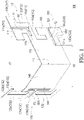
- FIG. 1 is a schematic diagram of an antenna structure according to an embodiment of the present disclosure.
- FIG. 2 is a schematic diagram of the antenna structure of FIG. 1 from another viewing angle.
- the antenna structure 100 is a multi-band antenna structure, and operates at two or more operating frequencies.
- One operating frequency may range from 2400 MHz to 2500 MHz and another operating frequency may range from 5150 MHz to 5850 MHz.
- the present disclosure is not limited thereto.
- the antenna structure 100 includes a first antenna 110, a second antenna 120, a third antenna 130, and a first grounding portion 140.
- the antenna structure 100 may be made by stamping and is an integrally formed metal sheet structure.
- the first grounding portion 140 includes a first side edge 141 and a second side edge 142 opposite to each other.
- the first antenna 110 and the second antenna 120 are connected to the first side edge 141 and the third antenna 130 is connected to the second side edge 142.
- the first antenna 110 and the second antenna 120 operate at a first frequency, for example, ranging from 5150 MHz to 5850 MHz.
- the third antenna 130 operates at a second frequency, for example, ranging from 2400 MHz to 2500 MHz.
- the third antenna 130 may also operate at another frequency, for example, ranging from 5150 MHz to 5850 MHz, or may operate at another operating frequency satisfying the first generation (1G) to fifth generation (5G) mobile communications technology standards, depending on design requirements.
- the first antenna 110, the second antenna 120, and the third antenna 130 are respectively located at two opposite sides of the first grounding portion 140, to prevent the first antenna 110 and the second antenna 120 from being too close to and interfering with the third antenna 130, thereby providing good isolation.
- the first antenna 110 and the second antenna 120 are disposed side by side on the same side (that is, the first side edge 141 of the first grounding portion 140) and are orthogonally polarized, so that the distance between the first antenna 110 and the second antenna 120 can be reduced while maintaining high isolation, thereby reducing the configuration space required by the antenna structure 100.
- the antenna structure 100 is basically divided into three configuration planes.
- the first antenna 110 and the second antenna 120 are disposed on a first plane S1
- the third antenna 130 is disposed on a second plane S2
- the first grounding portion 140 is disposed on a third plane S3.
- the configuration of the first antenna 110 and the second antenna 120 on the same plane S1 helps reduce the configuration space required by the antenna structure 100.
- An angle A1 between the first plane S1 and the second plane S2 ranges from 75 degrees to 90 degrees, to ensure that a sufficient distance is maintained between the first antenna 110 and second antenna 120 and the third antenna 130.
- an angle A2 between the first plane S1 and the third plane S3 is an obtuse angle
- an angle A3 between the second plane S2 and the third plane S3 is an obtuse angle
- the antenna structure 100 further includes a second grounding portion 150.
- the first antenna 110 and the second antenna 120 are connected to the first side edge 141 of the first grounding portion 140 through the second grounding portion 150, and the first antenna 110, the second antenna 120, and the second grounding portion 150 are disposed on the same plane (that is, the first plane S1), thereby reducing the configuration space required by the antenna structure 100.
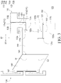
- FIG. 3 is a schematic side view taken from the front side of the first antenna and the second antenna of FIG. 1 .
- FIG. 4 is a schematic side view taken from the front side of the third antenna of FIG. 1 .
- the first antenna 110 includes a first slot 111 dividing the first antenna 110 into two first branches 112.
- the first slot 111 includes a first segment 111a extending along a direction D1 and a second segment 111b extending along a direction D2 perpendicular to the direction D1.
- the second segment 111b extends toward the first side edge 141 of the first grounding portion 140, and an end 111c of the second segment 111b does not reach the first side edge 141 of the first grounding portion 140.
- the second antenna 120 includes a second slot 121 dividing the second antenna 120 into two second branches 122.
- the second slot 121 extends toward the first side edge 141 of the first grounding portion 140 along the direction D2, and an end 121a of the second slot 121 does not reach the first side edge 141 of the first grounding portion 140.
- the shortest distance between the first antenna 110 and the third antenna 130 is the shortest distance G1 between the end 111c of the second segment 111b of the first slot 111 and the second side edge 142 of the first grounding portion 140.
- the shortest distance between the second antenna 120 and the third antenna 130 is the shortest distance G2 between the end 121a of the second slot 121 and the second side edge 142 of the first grounding portion 140.
- the shortest distance G1 is greater than the shortest distance G2, and the shortest distance G2 ranges, for example, from 30 mm to 35 mm, to prevent the first antenna 110 and the second antenna 120 from being too close to and interfering with the third antenna 130, thereby providing good isolation.
- each of the first branches 112 of the first antenna 110 includes a connection portion 112a, a radiation portion 112b, and an extension portion 112c.
- the two connection portions 112a are separated by the second segment 111b of the first slot 111 and are connected to the second grounding portion 150.
- the two extension portions 112c are separated by the first segment 111a of the first slot 111.
- the extension portion 112c is connected to the radiation portion 112b and the connection portion 112a.
- the two radiation portions 112b are separated by the first segment 111a and respectively extend opposite to each other in the direction D2.
- the width of each radiation portion 112b is greater than the width of the corresponding extension portion 112c.
- the first antenna 110 includes a feed-in point F1 and a ground point GD1.
- the feed-in point F1 is located at the extension portion 112c of one of the first branches 112
- the ground point GD1 is located at the extension portion 112c of another first branch 112
- the length of each of the first branches 112 may be 1/4 ⁇ 1/8 wavelength with respect to the first frequency.
- the length of each first branch of the first antenna may be, but not limited to, 1/2 wavelength, 1/4 wavelength, or 1/8 wavelength with respect to the first frequency, depending on design requirements.
- each second branch 122 of the second antenna 120 includes a connection portion 122a and a radiation portion 122b.
- the two connection portions 122a are separated by the second slot 121.
- the two radiation portions 122b are separated by the second slot 121 and extend opposite to each other in the direction D1.
- the radiation portion 122b is connected to the second grounding portion 150 through the connection portion 122a.
- the width of the radiation portion 122b is greater than the width of the connection portion 122a.
- the second antenna 120 includes a feed-in point F2 and a ground point GD2.
- the feed-in point F2 is located at the connection portion 122a of one of the second branches 122, the ground point GD2 is located at the connection portion 122a of another second branch 122, and the length of each of the second branches 122 may be (1/4 ⁇ 1/8) wavelength with respect to the first frequency.
- the length of each second branch of the second antenna may be, but not limited to, 1/2 wavelength, 1/4 wavelength, or 1/8 wavelength with respect to the first frequency, depending on design requirements.
- the third antenna 130 includes a third slot 131 dividing the third antenna 130 into two third branches 132.
- the third slot 131 includes a first segment 131a and a second segment 131b.
- the first segment 131a is located between the second segment 131b and the second side edge 142 of the first grounding portion 140. Further, the first segment 131a extends along a direction D3, and the second segment 131b extends along a direction D4 perpendicular to the direction D3.
- Each third branch 132 of the third antenna 130 includes a connection portion 132a, a radiation portion 132b, and a bending portion 132c.
- connection portions 132a are separated by the first segment 131a and are connected to the second side edge 142 of the first grounding portion 140.
- the two bending portions 132c are separated by the second segment 131b. In each third branch 132, the bending portion 132c is configured to connect the radiation portion 132b and the connection portion 132a.
- the two third branches 132 are disposed at two opposite sides of the second segment 131b.
- the bending portion 132c of any of the third branches 132 first extends from the connection portion 132a toward the another third branch 132 along the direction D3, then extends away from the second side edge 142 of the first grounding portion 140 along the direction D4, and then extends away from the another third branch 132 along the direction D3, and finally the radiation portion 132b continues to extend toward the second side edge 142 of the first grounding portion 140 along the direction D4.
- the two radiation portions 132b are located at two opposite sides of the two bending portions 132c, and the two connection portions 132a are disposed side by side between the two radiation portions 132b.
- the width of each radiation portion 132b is greater than the width of an end segment of the corresponding bending portion 132c (that is, a segment, extending along the direction D3 and configured to connect to the radiation portion 132b, of the bending portion 132c).
- the two third branches 132 of the third antenna 130 may be configured to transmit or receive electric waves from two different directions.
- the third antenna 130 includes a feed-in point F3 and a ground point GD3.
- the feed-in point F3 is located at the bending portion 132c of one of the third branches 132.
- the ground point GD3 is located at the bending portion 132c of another third branch 132.
- the feed-in point F3 and the ground point GD3 are, for example, respectively located at segments, extending along the direction D4, of the corresponding bending portions 132c.
- the length of each third branch 132 may be 1/4 ⁇ 1/8 wavelength with respect to the second operating frequency. In another embodiment, the length of each third branch of the third antenna may be, but not limited to, 1/2 wavelength, 1/4 wavelength, or 1/8 wavelength with respect to the second operating frequency, depending on design requirements.
- FIG. 5 is a schematic diagram illustrating a frequency-return loss relationship of the antenna structure of FIG. 1 .
- a resonance mode obtained by the first antenna 110 is represented by a solid line
- a resonance mode obtained by the second antenna 120 is represented by a dashed line
- a resonance mode obtained by the third antenna 130 is represented by a dotted-dashed line.
- return losses of the resonance mode obtained by the third antenna 130 are all less than or equal to -10 dB, providing good performance.
- return losses of the resonance mode obtained by the first antenna 110 are all less than or equal to -10 dB, providing good performance.
- return losses of the resonance mode obtained by the second antenna 120 are all less than or equal to -10 dB, providing good performance.
- FIG. 6 is a schematic diagram illustrating a frequency-isolation relationship of the antenna structure of FIG. 1 .
- isolation between the third antenna 130 and the first antenna 110 is represented by a solid line
- isolation between the third antenna 130 and the second antenna 120 is represented by a dashed line
- isolation between the first antenna 110 and the second antenna 120 is represented by a dotted-dashed line. It can be seen from FIG. 6 that the foregoing isolations are all lower than -20 dB. Therefore, the first antenna 110, the second antenna 120, and the third antenna 130 do not interfere with each other.
- FIG. 7A to FIG. 7C are schematic diagrams of radiation patterns of the antenna structure of FIG. 1 in an X-Y plane, an X-Z plane, and a Y-Z plane.
- a radiation pattern of the first antenna 110 in the X-Y plane, the X-Z plane, and the Y-Z plane is represented by a solid line
- a radiation pattern of the second antenna 120 in the X-Y plane, the X-Z plane, and the Y-Z plane is represented by a dashed line
- a radiation pattern of the third antenna 130 in the X-Y plane, the X-Z plane, and the Y-Z plane is represented by a dotted-dashed line.
- the first antenna 110, the second antenna 120, and the third antenna 130 have good omnidirectional performance.
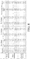
- FIG. 8 is a diagram illustrating a gain-efficiency relationship of the first antenna, the second antenna and the third antenna shown in FIG. 1 .
- the first antenna 110 and the second antenna 120 operate at five frequencies (5150 MHz, 5350 MHz, 5470 MHz, 5725 MHz, and 5850 MHz) and the third antenna 130 operates at three frequencies (2400 MHz, 2450 MHz, and 2500 MHz)
- measurement is performed on the X-Y plane, X-Z plane, and Y-Z plane, and a maximum gain, an average gain, a sum of polarization vectors, and efficiency of each antenna at a particular frequency and in a particular plane are respectively recorded. It can be seen from FIG.
- the antenna structure 100 has good wireless transmission efficiency and quality.
- FIG. 9 is a schematic diagram of an electronic device according to an embodiment of the present disclosure.
- the electronic device 10 uses the antenna structure 100 of the foregoing embodiments, and the number of antenna structures 100 is at least one.
- the electronic device 10 includes a body 11, and the antenna structures 100 are evenly distributed around the body 11 and are electrically connected to the body 11, to transmit or receive electric waves at particular frequencies to or from different directions. Because the antenna structure 100 can operate at multiple frequencies, the number of antennas required by the electronic device 10 can be reduced, thereby reducing manufacturing costs and meeting the design requirements of product miniaturization.
- the first antenna 110 and the second antenna 120 of one of the antenna structures 100 and the third antenna 130 of another antenna structure 100 are disposed at each side of the body 11, and to prevent the first antenna 110, the second antenna 120, and the third antenna 130 located at the same side of the body 11 from interfering with each other, the first antenna 110 and the second antenna 120 disposed side by side are orthogonally polarized.
- the shortest distance G3 between the first antenna 110 and the third antenna 130 is greater than or equal to 38 mm to improve isolation.
- the shortest distance between the second antenna 120 and the third antenna 130 is greater than the shortest distance G3.
- the antenna structure of the present disclosure integrates a plurality of antennas, and the antennas operate at two or more different frequencies.
- polarization directions of antennas with the same frequency are orthogonal to each other, so that the isolation between the antennas can be increased. Therefore, the antenna structure and the electronic device using the antenna structure of the present disclosure not only can operate at multiple frequencies, but also have good wireless transmission quality.
- the electronic device using the antenna structure can reduce the number of antennas required, thereby reducing the manufacturing costs and meeting the design requirements of product miniaturization.
Landscapes
- Engineering & Computer Science (AREA)
- Computer Networks & Wireless Communication (AREA)
- Physics & Mathematics (AREA)
- Electromagnetism (AREA)
- Variable-Direction Aerials And Aerial Arrays (AREA)
- Waveguide Aerials (AREA)
Claims (12)
- Antennenstruktur (100), die umfasst:eine erste Antenne (110), die bei einer ersten Frequenz arbeitet;eine zweite Antenne (120), die bei der ersten Frequenz arbeitet, wobei die erste Antenne (110) Seite an Seite mit der zweiten Antenne (120) angeordnet ist und die erste Antenne (110) und die zweite Antenne (120) orthogonal polarisiert sind;eine dritte Antenne (130), die bei einer zweiten Frequenz arbeitet, wobei die zweite Frequenz niedriger ist als die erste Frequenz; undeinen ersten Erdungsabschnitt (140), der eine erste Seitenkante (141) und eine zweite Seitenkante (142) umfasst, die einander gegenüberliegen, wobei die erste Antenne (110) und die zweite Antenne (120) mit der ersten Seitenkante (141) verbunden sind und die dritte Antenne (130) mit der zweiten Seitenkante (142) verbunden ist, dadurch gekennzeichnet, dassdie erste Antenne (110) und die zweite Antenne (120) auf einer ersten Ebene (S1) angeordnet sind, die dritte Antenne (130) auf einer zweiten Ebene (S2) angeordnet ist, der erste Erdungsabschnitt (140) auf einer dritten Ebene (S3) angeordnet ist, ein Winkel (A2) zwischen der ersten Ebene (S1) und der dritten Ebene (S3) ein stumpfer Winkel ist, und ein Winkel (A3) zwischen der zweiten Ebene (S2) und der dritten Ebene (S3) ein stumpfer Winkel ist.
- Antennenstruktur (100) gemäß Anspruch 1, wobei ein Winkel (A1) zwischen der ersten Ebene (S1) und der zweiten Ebene (S2) im Bereich von 75 Grad bis 90 Grad liegt.
- Antennenstruktur (100) gemäß einem der Ansprüche 1 bis 2, wobei ein kürzester Abstand (G2) zwischen der zweiten Antenne (120) und der dritten Antenne (130) im Bereich von 30 mm bis 35 mm liegt.
- Antennenstruktur (100) gemäß einem der Ansprüche 1 bis 3, wobei die erste Antenne (110) einen ersten Schlitz (111) aufweist, der die erste Antenne (110) in zwei erste Zweige (112) unterteilt, und die zweite Antenne (120) einen zweiten Schlitz (121) aufweist, der die zweite Antenne (120) in zwei zweite Zweige (122) unterteilt, wobeider erste Schlitz (111) ein erstes Segment (111a), das sich entlang einer ersten Richtung (D1) erstreckt, und ein zweites Segment (111b), das sich entlang einer zweiten Richtung (D2) erstreckt, umfasst, die erste Richtung (D1) und die zweite Richtung (D2) senkrecht zueinander sind, das zweite Segment (111b) sich in Richtung der ersten Seitenkante (141) des ersten Erdungsabschnitts (140) erstreckt, ein Ende (111c) des zweiten Segments (111b) die erste Seitenkante (141) des ersten Erdungsabschnitts (140) nicht erreicht, undder zweite Schlitz (121) sich in Richtung der ersten Seitenkante (141) des ersten Erdungsabschnitts (140) entlang der zweiten Richtung (D2) erstreckt, und ein Ende (121a) des zweiten Schlitzes (121) die erste Seitenkante (141) des ersten Erdungsabschnitts (140) nicht erreicht.
- Antennenstruktur (100) gemäß Anspruch 4, wobei ein erster Abstand zwischen dem Ende (111c) des zweiten Segments (111b) des ersten Schlitzes (111) und der ersten Seitenkante (141) des ersten Erdungsabschnitts (140) kleiner ist als ein zweiter Abstand zwischen dem Ende (121a) des zweiten Schlitzes (121) und der ersten Seitenkante (141) des ersten Erdungsabschnitts (140).
- Antennenstruktur (100) gemäß einem der Ansprüche 1 bis 5, wobei die dritte Antenne (130) einen dritten Schlitz (131) aufweist, der die dritte Antenne (130) in zwei Zweige (132) unterteilt, der dritte Schlitz (131) ein erstes Segment (131a) und ein zweites Segment (131b) aufweist, das erste Segment (131a) und das zweite Segment (131b) senkrecht zueinander stehen und das erste Segment (131a) zwischen dem zweiten Segment (131b) und der zweiten Seitenkante (142) des ersten Erdungsabschnitts (140) angeordnet ist.
- Antennenstruktur (100) gemäß Anspruch 6, wobei jeder der Zweige (132) der dritten Antenne (130) einen Verbindungsabschnitt (132a), einen Strahlungsabschnitt (132b) und einen Biegeabschnitt (132c) umfasst, der den Verbindungsabschnitt (132a) und den Strahlungsabschnitt (132b) verbindet, die beiden Verbindungsabschnitte (132a) mit der zweiten Seitenkante (142) des ersten Erdungsabschnitts (140) verbunden sind, die beiden Verbindungsabschnitte (132a) durch das erste Segment (131a) getrennt sind, die beiden Biegeabschnitte (132c) durch das zweite Segment (131b) getrennt sind, und die beiden Strahlungsabschnitte (132b) an zwei gegenüberliegenden Seiten der beiden Biegeabschnitte (132c) angeordnet sind.
- Antennenstruktur (100) gemäß einem der Ansprüche 1 bis 7, die ferner einen zweiten Erdungsabschnitt (150) umfasst, wobei die erste Antenne (110) und die zweite Antenne (120) über den zweiten Erdungsabschnitt (150) mit der ersten Seitenkante (141) des ersten Erdungsabschnitts (140) verbunden sind und die erste Antenne (110), die zweite Antenne (120) und der zweite Erdungsabschnitt (150) auf derselben Ebene (S1) angeordnet sind.
- Antennenstruktur (100) gemäß einem der Ansprüche 1 bis 8, wobei die erste Antenne (110), die zweite Antenne (120), der erste Erdungsabschnitt (140) und die dritte Antenne (130) eine einstückig ausgebildete Metallblattstruktur sind.
- Elektronische Vorrichtung (10), die umfasst:einen Körper (11), undmindestens eine Antennenstruktur (100) gemäß einem der Ansprüche 1 bis 9, die um den Körper (11) herum angeordnet ist und mit dem Körper (11) elektrisch verbunden ist.
- Elektronisches Vorrichtung (10) gemäß Anspruch 10, wobei die Anzahl der Antennenstrukturen (100) mindestens zwei beträgt und die erste Antenne (110) einer der beiden Antennenstrukturen (100) und die dritte Antenne (130) einer anderen der beiden Antennenstrukturen (100) auf der gleichen Seite des Körpers (11) angeordnet sind.
- Elektronische Vorrichtung (10) gemäß Anspruch 11, wobei ein kürzester Abstand (G3) zwischen der ersten Antenne (110) einer der beiden Antennenstrukturen (100) und der dritten Antenne (130) der anderen der beiden Antennenstrukturen (100) größer oder gleich 38 mm ist.
Applications Claiming Priority (1)
| Application Number | Priority Date | Filing Date | Title |
|---|---|---|---|
| TW108201011U TWM579391U (zh) | 2019-01-21 | 2019-01-21 | 電子裝置及其天線結構 |
Publications (2)
| Publication Number | Publication Date |
|---|---|
| EP3683890A1 EP3683890A1 (de) | 2020-07-22 |
| EP3683890B1 true EP3683890B1 (de) | 2022-09-07 |
Family
ID=67703314
Family Applications (1)
| Application Number | Title | Priority Date | Filing Date |
|---|---|---|---|
| EP19213179.5A Active EP3683890B1 (de) | 2019-01-21 | 2019-12-03 | Elektronische vorrichtung und antennenstruktur davon |
Country Status (6)
| Country | Link |
|---|---|
| US (1) | US11177583B2 (de) |
| EP (1) | EP3683890B1 (de) |
| JP (1) | JP3224820U (de) |
| KR (1) | KR200493613Y1 (de) |
| CN (1) | CN210576445U (de) |
| TW (1) | TWM579391U (de) |
Families Citing this family (8)
| Publication number | Priority date | Publication date | Assignee | Title |
|---|---|---|---|---|
| TWI714372B (zh) * | 2019-11-29 | 2020-12-21 | 緯創資通股份有限公司 | 天線結構 |
| TWI746221B (zh) * | 2020-10-21 | 2021-11-11 | 和碩聯合科技股份有限公司 | 天線模組 |
| TWI775510B (zh) * | 2021-07-02 | 2022-08-21 | 宏碁股份有限公司 | 支援多輸入多輸出之行動裝置 |
| US12113299B2 (en) * | 2021-09-17 | 2024-10-08 | Htc Corporation | Signal radiation device and antenna structure |
| CN116264350A (zh) * | 2021-12-15 | 2023-06-16 | 华为技术有限公司 | 天线和电子设备 |
| CN116799490A (zh) * | 2022-03-16 | 2023-09-22 | 上海莫仕连接器有限公司 | 天线装置 |
| CN119153931A (zh) * | 2023-06-16 | 2024-12-17 | 英业达科技有限公司 | 电子装置及天线模组 |
| USD1125133S1 (en) * | 2025-01-14 | 2026-05-05 | Vdw Design, Llc | Dual-polarized antenna |
Citations (1)
| Publication number | Priority date | Publication date | Assignee | Title |
|---|---|---|---|---|
| EP1376760A2 (de) * | 2002-06-19 | 2004-01-02 | Andrew Corporation | Einteilige, doppelt gefaltete Dipolantenne |
Family Cites Families (21)
| Publication number | Priority date | Publication date | Assignee | Title |
|---|---|---|---|---|
| US5723939A (en) | 1994-12-28 | 1998-03-03 | Matsushita Electronics Corporation | Circular fluorescent lamp |
| DE19823749C2 (de) * | 1998-05-27 | 2002-07-11 | Kathrein Werke Kg | Dualpolarisierte Mehrbereichsantenne |
| US6686886B2 (en) | 2001-05-29 | 2004-02-03 | International Business Machines Corporation | Integrated antenna for laptop applications |
| US20040257283A1 (en) | 2003-06-19 | 2004-12-23 | International Business Machines Corporation | Antennas integrated with metallic display covers of computing devices |
| TWI318809B (en) | 2005-05-23 | 2009-12-21 | Hon Hai Prec Ind Co Ltd | Multi-frequency antenna |
| US8115686B2 (en) * | 2005-07-21 | 2012-02-14 | Fractus, S.A. | Handheld device with two antennas, and method of enhancing the isolation between the antennas |
| KR100883408B1 (ko) * | 2006-09-11 | 2009-03-03 | 주식회사 케이엠더블유 | 이동통신 기지국용 이중대역 이중편파 안테나 |
| US8207898B2 (en) * | 2007-01-12 | 2012-06-26 | Panasonic Corporation | Antenna unit and communication apparatus |
| TWI380510B (en) * | 2007-12-10 | 2012-12-21 | Hon Hai Prec Ind Co Ltd | Multi-band antenna |
| JP5312598B2 (ja) * | 2008-09-22 | 2013-10-09 | ケーエムダブリュ・インコーポレーテッド | 移動通信基地局用二重帯域二重偏波アンテナ |
| TWM359814U (en) | 2009-03-06 | 2009-06-21 | Cheng Uei Prec Ind Co Ltd | Multiband antenna |
| JP5314610B2 (ja) * | 2010-02-01 | 2013-10-16 | 日立電線株式会社 | 複合アンテナ装置 |
| JP5441793B2 (ja) * | 2010-03-30 | 2014-03-12 | 日本板硝子株式会社 | ガラスアンテナ |
| US9281565B2 (en) * | 2010-09-17 | 2016-03-08 | Advanced-Connectek Inc. | Multi-frequency antenna |
| KR101378847B1 (ko) * | 2012-07-27 | 2014-03-27 | 엘에스엠트론 주식회사 | 광대역 특성을 갖는 내장형 안테나 |
| GB2509297A (en) * | 2012-10-11 | 2014-07-02 | Microsoft Corp | Multiband antenna |
| JP6102211B2 (ja) * | 2012-11-20 | 2017-03-29 | 船井電機株式会社 | マルチアンテナ装置および通信機器 |
| TWI548145B (zh) * | 2013-01-07 | 2016-09-01 | 智易科技股份有限公司 | 全向式天線 |
| KR20150029172A (ko) | 2013-09-09 | 2015-03-18 | 삼성전자주식회사 | 안테나유닛을 구비한 신호중계장치 |
| CN106898880B (zh) * | 2015-12-21 | 2020-01-07 | 小米科技有限责任公司 | 天线组件及电子设备 |
| US10270185B2 (en) * | 2016-12-19 | 2019-04-23 | Huawei Technologies Co., Ltd. | Switchable dual band antenna array with three orthogonal polarizations |
-
2019
- 2019-01-21 TW TW108201011U patent/TWM579391U/zh unknown
- 2019-09-26 KR KR2020190003930U patent/KR200493613Y1/ko active Active
- 2019-11-05 JP JP2019004192U patent/JP3224820U/ja active Active
- 2019-11-18 CN CN201921986497.3U patent/CN210576445U/zh active Active
- 2019-11-29 US US16/699,467 patent/US11177583B2/en active Active
- 2019-12-03 EP EP19213179.5A patent/EP3683890B1/de active Active
Patent Citations (1)
| Publication number | Priority date | Publication date | Assignee | Title |
|---|---|---|---|---|
| EP1376760A2 (de) * | 2002-06-19 | 2004-01-02 | Andrew Corporation | Einteilige, doppelt gefaltete Dipolantenne |
Also Published As
| Publication number | Publication date |
|---|---|
| TWM579391U (zh) | 2019-06-11 |
| EP3683890A1 (de) | 2020-07-22 |
| KR200493613Y1 (ko) | 2021-05-04 |
| KR20200001704U (ko) | 2020-07-30 |
| US11177583B2 (en) | 2021-11-16 |
| CN210576445U (zh) | 2020-05-19 |
| JP3224820U (ja) | 2020-01-23 |
| US20200235495A1 (en) | 2020-07-23 |
Similar Documents
| Publication | Publication Date | Title |
|---|---|---|
| US11177583B2 (en) | Electronic device and antenna structure thereof | |
| CN201655979U (zh) | 复合式多输入多输出天线模块及其系统 | |
| US7148849B2 (en) | Multi-band antenna | |
| US20050073462A1 (en) | Multi-band antenna | |
| CN101043100B (zh) | 一种具有槽型导体与带状导体的多频天线 | |
| EP2493015B1 (de) | Mobiles Kommunikationsgerät und Antennenstruktur dafür | |
| AU762442B2 (en) | Antenna, radio device and radio repeater | |
| EP3171455B1 (de) | Antennenmodul | |
| US20060170600A1 (en) | Internal multiband antenna | |
| US20050200535A1 (en) | Antenna structures and their use in wireless communication devices | |
| US10938100B2 (en) | Dual-feed loop antenna structure and electronic device | |
| US11581650B2 (en) | Multi-input multi-output antenna structure | |
| EP3828998B1 (de) | Endgerät | |
| MXPA00010804A (es) | Antena dipolo doblada. | |
| TW201826621A (zh) | 多天線裝置 | |
| CN118160151B (zh) | 天线单元、天线及天馈系统 | |
| US7148848B2 (en) | Dual band, bent monopole antenna | |
| US12444849B2 (en) | Antenna module | |
| CN114583448B (zh) | 一种用于5g移动通信的紧凑型三单元终端mimo天线阵 | |
| CN119096423A (zh) | 用于mimo天线应用的天线布置结构 | |
| US20240388009A1 (en) | Base station antennas having multi-band radiating units that include integrated first and second frequency band radiating elements | |
| US11437717B2 (en) | Antenna system | |
| CN212136690U (zh) | 小型化通信与卫星定位组合天线 | |
| JP2592128Y2 (ja) | 平型アンテナ | |
| US20080094303A1 (en) | Planer inverted-F antenna device |
Legal Events
| Date | Code | Title | Description |
|---|---|---|---|
| PUAI | Public reference made under article 153(3) epc to a published international application that has entered the european phase |
Free format text: ORIGINAL CODE: 0009012 |
|
| STAA | Information on the status of an ep patent application or granted ep patent |
Free format text: STATUS: THE APPLICATION HAS BEEN PUBLISHED |
|
| AK | Designated contracting states |
Kind code of ref document: A1 Designated state(s): AL AT BE BG CH CY CZ DE DK EE ES FI FR GB GR HR HU IE IS IT LI LT LU LV MC MK MT NL NO PL PT RO RS SE SI SK SM TR |
|
| AX | Request for extension of the european patent |
Extension state: BA ME |
|
| STAA | Information on the status of an ep patent application or granted ep patent |
Free format text: STATUS: REQUEST FOR EXAMINATION WAS MADE |
|
| 17P | Request for examination filed |
Effective date: 20201229 |
|
| RBV | Designated contracting states (corrected) |
Designated state(s): AL AT BE BG CH CY CZ DE DK EE ES FI FR GB GR HR HU IE IS IT LI LT LU LV MC MK MT NL NO PL PT RO RS SE SI SK SM TR |
|
| REG | Reference to a national code |
Ref country code: DE Ref legal event code: R079 Ref document number: 602019019215 Country of ref document: DE Free format text: PREVIOUS MAIN CLASS: H01Q0009280000 Ipc: H01Q0001240000 |
|
| GRAP | Despatch of communication of intention to grant a patent |
Free format text: ORIGINAL CODE: EPIDOSNIGR1 |
|
| STAA | Information on the status of an ep patent application or granted ep patent |
Free format text: STATUS: GRANT OF PATENT IS INTENDED |
|
| RIC1 | Information provided on ipc code assigned before grant |
Ipc: H01Q 1/22 20060101ALI20220404BHEP Ipc: H01Q 9/28 20060101ALI20220404BHEP Ipc: H01Q 25/00 20060101ALI20220404BHEP Ipc: H01Q 21/28 20060101ALI20220404BHEP Ipc: H01Q 21/24 20060101ALI20220404BHEP Ipc: H01Q 9/26 20060101ALI20220404BHEP Ipc: H01Q 5/307 20150101ALI20220404BHEP Ipc: H01Q 5/20 20150101ALI20220404BHEP Ipc: H01Q 1/52 20060101ALI20220404BHEP Ipc: H01Q 1/24 20060101AFI20220404BHEP |
|
| INTG | Intention to grant announced |
Effective date: 20220504 |
|
| GRAS | Grant fee paid |
Free format text: ORIGINAL CODE: EPIDOSNIGR3 |
|
| GRAA | (expected) grant |
Free format text: ORIGINAL CODE: 0009210 |
|
| STAA | Information on the status of an ep patent application or granted ep patent |
Free format text: STATUS: THE PATENT HAS BEEN GRANTED |
|
| AK | Designated contracting states |
Kind code of ref document: B1 Designated state(s): AL AT BE BG CH CY CZ DE DK EE ES FI FR GB GR HR HU IE IS IT LI LT LU LV MC MK MT NL NO PL PT RO RS SE SI SK SM TR |
|
| REG | Reference to a national code |
Ref country code: GB Ref legal event code: FG4D |
|
| REG | Reference to a national code |
Ref country code: CH Ref legal event code: EP Ref country code: AT Ref legal event code: REF Ref document number: 1517823 Country of ref document: AT Kind code of ref document: T Effective date: 20220915 |
|
| REG | Reference to a national code |
Ref country code: DE Ref legal event code: R096 Ref document number: 602019019215 Country of ref document: DE |
|
| REG | Reference to a national code |
Ref country code: IE Ref legal event code: FG4D |
|
| REG | Reference to a national code |
Ref country code: LT Ref legal event code: MG9D |
|
| REG | Reference to a national code |
Ref country code: NL Ref legal event code: MP Effective date: 20220907 |
|
| PG25 | Lapsed in a contracting state [announced via postgrant information from national office to epo] |
Ref country code: SE Free format text: LAPSE BECAUSE OF FAILURE TO SUBMIT A TRANSLATION OF THE DESCRIPTION OR TO PAY THE FEE WITHIN THE PRESCRIBED TIME-LIMIT Effective date: 20220907 Ref country code: RS Free format text: LAPSE BECAUSE OF FAILURE TO SUBMIT A TRANSLATION OF THE DESCRIPTION OR TO PAY THE FEE WITHIN THE PRESCRIBED TIME-LIMIT Effective date: 20220907 Ref country code: NO Free format text: LAPSE BECAUSE OF FAILURE TO SUBMIT A TRANSLATION OF THE DESCRIPTION OR TO PAY THE FEE WITHIN THE PRESCRIBED TIME-LIMIT Effective date: 20221207 Ref country code: LV Free format text: LAPSE BECAUSE OF FAILURE TO SUBMIT A TRANSLATION OF THE DESCRIPTION OR TO PAY THE FEE WITHIN THE PRESCRIBED TIME-LIMIT Effective date: 20220907 Ref country code: LT Free format text: LAPSE BECAUSE OF FAILURE TO SUBMIT A TRANSLATION OF THE DESCRIPTION OR TO PAY THE FEE WITHIN THE PRESCRIBED TIME-LIMIT Effective date: 20220907 Ref country code: FI Free format text: LAPSE BECAUSE OF FAILURE TO SUBMIT A TRANSLATION OF THE DESCRIPTION OR TO PAY THE FEE WITHIN THE PRESCRIBED TIME-LIMIT Effective date: 20220907 |
|
| REG | Reference to a national code |
Ref country code: AT Ref legal event code: MK05 Ref document number: 1517823 Country of ref document: AT Kind code of ref document: T Effective date: 20220907 |
|
| PG25 | Lapsed in a contracting state [announced via postgrant information from national office to epo] |
Ref country code: HR Free format text: LAPSE BECAUSE OF FAILURE TO SUBMIT A TRANSLATION OF THE DESCRIPTION OR TO PAY THE FEE WITHIN THE PRESCRIBED TIME-LIMIT Effective date: 20220907 Ref country code: GR Free format text: LAPSE BECAUSE OF FAILURE TO SUBMIT A TRANSLATION OF THE DESCRIPTION OR TO PAY THE FEE WITHIN THE PRESCRIBED TIME-LIMIT Effective date: 20221208 |
|
| PG25 | Lapsed in a contracting state [announced via postgrant information from national office to epo] |
Ref country code: SM Free format text: LAPSE BECAUSE OF FAILURE TO SUBMIT A TRANSLATION OF THE DESCRIPTION OR TO PAY THE FEE WITHIN THE PRESCRIBED TIME-LIMIT Effective date: 20220907 Ref country code: RO Free format text: LAPSE BECAUSE OF FAILURE TO SUBMIT A TRANSLATION OF THE DESCRIPTION OR TO PAY THE FEE WITHIN THE PRESCRIBED TIME-LIMIT Effective date: 20220907 Ref country code: PT Free format text: LAPSE BECAUSE OF FAILURE TO SUBMIT A TRANSLATION OF THE DESCRIPTION OR TO PAY THE FEE WITHIN THE PRESCRIBED TIME-LIMIT Effective date: 20230109 Ref country code: ES Free format text: LAPSE BECAUSE OF FAILURE TO SUBMIT A TRANSLATION OF THE DESCRIPTION OR TO PAY THE FEE WITHIN THE PRESCRIBED TIME-LIMIT Effective date: 20220907 Ref country code: CZ Free format text: LAPSE BECAUSE OF FAILURE TO SUBMIT A TRANSLATION OF THE DESCRIPTION OR TO PAY THE FEE WITHIN THE PRESCRIBED TIME-LIMIT Effective date: 20220907 Ref country code: AT Free format text: LAPSE BECAUSE OF FAILURE TO SUBMIT A TRANSLATION OF THE DESCRIPTION OR TO PAY THE FEE WITHIN THE PRESCRIBED TIME-LIMIT Effective date: 20220907 |
|
| PG25 | Lapsed in a contracting state [announced via postgrant information from national office to epo] |
Ref country code: SK Free format text: LAPSE BECAUSE OF FAILURE TO SUBMIT A TRANSLATION OF THE DESCRIPTION OR TO PAY THE FEE WITHIN THE PRESCRIBED TIME-LIMIT Effective date: 20220907 Ref country code: PL Free format text: LAPSE BECAUSE OF FAILURE TO SUBMIT A TRANSLATION OF THE DESCRIPTION OR TO PAY THE FEE WITHIN THE PRESCRIBED TIME-LIMIT Effective date: 20220907 Ref country code: IS Free format text: LAPSE BECAUSE OF FAILURE TO SUBMIT A TRANSLATION OF THE DESCRIPTION OR TO PAY THE FEE WITHIN THE PRESCRIBED TIME-LIMIT Effective date: 20230107 Ref country code: EE Free format text: LAPSE BECAUSE OF FAILURE TO SUBMIT A TRANSLATION OF THE DESCRIPTION OR TO PAY THE FEE WITHIN THE PRESCRIBED TIME-LIMIT Effective date: 20220907 |
|
| REG | Reference to a national code |
Ref country code: DE Ref legal event code: R097 Ref document number: 602019019215 Country of ref document: DE |
|
| PG25 | Lapsed in a contracting state [announced via postgrant information from national office to epo] |
Ref country code: NL Free format text: LAPSE BECAUSE OF FAILURE TO SUBMIT A TRANSLATION OF THE DESCRIPTION OR TO PAY THE FEE WITHIN THE PRESCRIBED TIME-LIMIT Effective date: 20220907 Ref country code: AL Free format text: LAPSE BECAUSE OF FAILURE TO SUBMIT A TRANSLATION OF THE DESCRIPTION OR TO PAY THE FEE WITHIN THE PRESCRIBED TIME-LIMIT Effective date: 20220907 |
|
| PLBE | No opposition filed within time limit |
Free format text: ORIGINAL CODE: 0009261 |
|
| STAA | Information on the status of an ep patent application or granted ep patent |
Free format text: STATUS: NO OPPOSITION FILED WITHIN TIME LIMIT |
|
| PG25 | Lapsed in a contracting state [announced via postgrant information from national office to epo] |
Ref country code: DK Free format text: LAPSE BECAUSE OF FAILURE TO SUBMIT A TRANSLATION OF THE DESCRIPTION OR TO PAY THE FEE WITHIN THE PRESCRIBED TIME-LIMIT Effective date: 20220907 |
|
| REG | Reference to a national code |
Ref country code: CH Ref legal event code: PL |
|
| 26N | No opposition filed |
Effective date: 20230608 |
|
| REG | Reference to a national code |
Ref country code: BE Ref legal event code: MM Effective date: 20221231 |
|
| PG25 | Lapsed in a contracting state [announced via postgrant information from national office to epo] |
Ref country code: SI Free format text: LAPSE BECAUSE OF FAILURE TO SUBMIT A TRANSLATION OF THE DESCRIPTION OR TO PAY THE FEE WITHIN THE PRESCRIBED TIME-LIMIT Effective date: 20220907 Ref country code: LU Free format text: LAPSE BECAUSE OF NON-PAYMENT OF DUE FEES Effective date: 20221203 |
|
| P01 | Opt-out of the competence of the unified patent court (upc) registered |
Effective date: 20230825 |
|
| PG25 | Lapsed in a contracting state [announced via postgrant information from national office to epo] |
Ref country code: LI Free format text: LAPSE BECAUSE OF NON-PAYMENT OF DUE FEES Effective date: 20221231 Ref country code: IE Free format text: LAPSE BECAUSE OF NON-PAYMENT OF DUE FEES Effective date: 20221203 Ref country code: CH Free format text: LAPSE BECAUSE OF NON-PAYMENT OF DUE FEES Effective date: 20221231 |
|
| PG25 | Lapsed in a contracting state [announced via postgrant information from national office to epo] |
Ref country code: BE Free format text: LAPSE BECAUSE OF NON-PAYMENT OF DUE FEES Effective date: 20221231 |
|
| PG25 | Lapsed in a contracting state [announced via postgrant information from national office to epo] |
Ref country code: HU Free format text: LAPSE BECAUSE OF FAILURE TO SUBMIT A TRANSLATION OF THE DESCRIPTION OR TO PAY THE FEE WITHIN THE PRESCRIBED TIME-LIMIT; INVALID AB INITIO Effective date: 20191203 |
|
| PG25 | Lapsed in a contracting state [announced via postgrant information from national office to epo] |
Ref country code: CY Free format text: LAPSE BECAUSE OF FAILURE TO SUBMIT A TRANSLATION OF THE DESCRIPTION OR TO PAY THE FEE WITHIN THE PRESCRIBED TIME-LIMIT Effective date: 20220907 |
|
| PG25 | Lapsed in a contracting state [announced via postgrant information from national office to epo] |
Ref country code: MK Free format text: LAPSE BECAUSE OF FAILURE TO SUBMIT A TRANSLATION OF THE DESCRIPTION OR TO PAY THE FEE WITHIN THE PRESCRIBED TIME-LIMIT Effective date: 20220907 Ref country code: IT Free format text: LAPSE BECAUSE OF FAILURE TO SUBMIT A TRANSLATION OF THE DESCRIPTION OR TO PAY THE FEE WITHIN THE PRESCRIBED TIME-LIMIT Effective date: 20220907 |
|
| PG25 | Lapsed in a contracting state [announced via postgrant information from national office to epo] |
Ref country code: MC Free format text: LAPSE BECAUSE OF FAILURE TO SUBMIT A TRANSLATION OF THE DESCRIPTION OR TO PAY THE FEE WITHIN THE PRESCRIBED TIME-LIMIT Effective date: 20220907 |
|
| PG25 | Lapsed in a contracting state [announced via postgrant information from national office to epo] |
Ref country code: TR Free format text: LAPSE BECAUSE OF FAILURE TO SUBMIT A TRANSLATION OF THE DESCRIPTION OR TO PAY THE FEE WITHIN THE PRESCRIBED TIME-LIMIT Effective date: 20220907 Ref country code: MC Free format text: LAPSE BECAUSE OF FAILURE TO SUBMIT A TRANSLATION OF THE DESCRIPTION OR TO PAY THE FEE WITHIN THE PRESCRIBED TIME-LIMIT Effective date: 20220907 |
|
| PG25 | Lapsed in a contracting state [announced via postgrant information from national office to epo] |
Ref country code: BG Free format text: LAPSE BECAUSE OF FAILURE TO SUBMIT A TRANSLATION OF THE DESCRIPTION OR TO PAY THE FEE WITHIN THE PRESCRIBED TIME-LIMIT Effective date: 20220907 |
|
| PG25 | Lapsed in a contracting state [announced via postgrant information from national office to epo] |
Ref country code: MT Free format text: LAPSE BECAUSE OF FAILURE TO SUBMIT A TRANSLATION OF THE DESCRIPTION OR TO PAY THE FEE WITHIN THE PRESCRIBED TIME-LIMIT Effective date: 20220907 |
|
| PGFP | Annual fee paid to national office [announced via postgrant information from national office to epo] |
Ref country code: DE Payment date: 20251120 Year of fee payment: 7 |
|
| PGFP | Annual fee paid to national office [announced via postgrant information from national office to epo] |
Ref country code: GB Payment date: 20251120 Year of fee payment: 7 |
|
| PGFP | Annual fee paid to national office [announced via postgrant information from national office to epo] |
Ref country code: FR Payment date: 20251120 Year of fee payment: 7 |