EP3683773A1 - Method of visualising a dynamic anatomical structure - Google Patents
Method of visualising a dynamic anatomical structure Download PDFInfo
- Publication number
- EP3683773A1 EP3683773A1 EP19152222.6A EP19152222A EP3683773A1 EP 3683773 A1 EP3683773 A1 EP 3683773A1 EP 19152222 A EP19152222 A EP 19152222A EP 3683773 A1 EP3683773 A1 EP 3683773A1
- Authority
- EP
- European Patent Office
- Prior art keywords
- volume
- interest
- dimensional
- dynamic
- visualisation
- Prior art date
- Legal status (The legal status is an assumption and is not a legal conclusion. Google has not performed a legal analysis and makes no representation as to the accuracy of the status listed.)
- Withdrawn
Links
Images


Classifications
-
- G—PHYSICS
- G06—COMPUTING OR CALCULATING; COUNTING
- G06T—IMAGE DATA PROCESSING OR GENERATION, IN GENERAL
- G06T7/00—Image analysis
- G06T7/0002—Inspection of images, e.g. flaw detection
- G06T7/0012—Biomedical image inspection
- G06T7/0014—Biomedical image inspection using an image reference approach
- G06T7/0016—Biomedical image inspection using an image reference approach involving temporal comparison
-
- G—PHYSICS
- G06—COMPUTING OR CALCULATING; COUNTING
- G06T—IMAGE DATA PROCESSING OR GENERATION, IN GENERAL
- G06T19/00—Manipulating three-dimensional [3D] models or images for computer graphics
-
- G—PHYSICS
- G06—COMPUTING OR CALCULATING; COUNTING
- G06T—IMAGE DATA PROCESSING OR GENERATION, IN GENERAL
- G06T15/00—Three-dimensional [3D] image rendering
- G06T15/08—Volume rendering
-
- G—PHYSICS
- G06—COMPUTING OR CALCULATING; COUNTING
- G06T—IMAGE DATA PROCESSING OR GENERATION, IN GENERAL
- G06T19/00—Manipulating three-dimensional [3D] models or images for computer graphics
- G06T19/006—Mixed reality
-
- G—PHYSICS
- G06—COMPUTING OR CALCULATING; COUNTING
- G06T—IMAGE DATA PROCESSING OR GENERATION, IN GENERAL
- G06T7/00—Image analysis
- G06T7/10—Segmentation; Edge detection
- G06T7/11—Region-based segmentation
-
- G—PHYSICS
- G06—COMPUTING OR CALCULATING; COUNTING
- G06T—IMAGE DATA PROCESSING OR GENERATION, IN GENERAL
- G06T7/00—Image analysis
- G06T7/20—Analysis of motion
- G06T7/246—Analysis of motion using feature-based methods, e.g. the tracking of corners or segments
-
- G—PHYSICS
- G06—COMPUTING OR CALCULATING; COUNTING
- G06V—IMAGE OR VIDEO RECOGNITION OR UNDERSTANDING
- G06V10/00—Arrangements for image or video recognition or understanding
- G06V10/20—Image preprocessing
- G06V10/25—Determination of region of interest [ROI] or a volume of interest [VOI]
-
- G—PHYSICS
- G06—COMPUTING OR CALCULATING; COUNTING
- G06V—IMAGE OR VIDEO RECOGNITION OR UNDERSTANDING
- G06V10/00—Arrangements for image or video recognition or understanding
- G06V10/40—Extraction of image or video features
- G06V10/62—Extraction of image or video features relating to a temporal dimension, e.g. time-based feature extraction; Pattern tracking
-
- G—PHYSICS
- G06—COMPUTING OR CALCULATING; COUNTING
- G06T—IMAGE DATA PROCESSING OR GENERATION, IN GENERAL
- G06T2207/00—Indexing scheme for image analysis or image enhancement
- G06T2207/10—Image acquisition modality
- G06T2207/10016—Video; Image sequence
-
- G—PHYSICS
- G06—COMPUTING OR CALCULATING; COUNTING
- G06T—IMAGE DATA PROCESSING OR GENERATION, IN GENERAL
- G06T2207/00—Indexing scheme for image analysis or image enhancement
- G06T2207/10—Image acquisition modality
- G06T2207/10072—Tomographic images
- G06T2207/10076—4D tomography; Time-sequential 3D tomography
-
- G—PHYSICS
- G06—COMPUTING OR CALCULATING; COUNTING
- G06T—IMAGE DATA PROCESSING OR GENERATION, IN GENERAL
- G06T2207/00—Indexing scheme for image analysis or image enhancement
- G06T2207/30—Subject of image; Context of image processing
- G06T2207/30004—Biomedical image processing
- G06T2207/30048—Heart; Cardiac
-
- G—PHYSICS
- G06—COMPUTING OR CALCULATING; COUNTING
- G06T—IMAGE DATA PROCESSING OR GENERATION, IN GENERAL
- G06T2210/00—Indexing scheme for image generation or computer graphics
- G06T2210/41—Medical
-
- G—PHYSICS
- G06—COMPUTING OR CALCULATING; COUNTING
- G06V—IMAGE OR VIDEO RECOGNITION OR UNDERSTANDING
- G06V2201/00—Indexing scheme relating to image or video recognition or understanding
- G06V2201/03—Recognition of patterns in medical or anatomical images
- G06V2201/031—Recognition of patterns in medical or anatomical images of internal organs
Definitions
- the dynamic model of at least a part of the anatomical structure is in particular a simplification of the anatomical structure, for example a triangulated surface model of a particular interface within the anatomical structure, for example the blood-tissue interface of a blood vessel or a heart chamber.
- the model may comprise a number of points spanning a line or a surface for each frame. It may also be a mathematical model, for example a parametrised model, such as a surface or volume spanned by spline curves.
- the model is dynamic, i.e. it follows the movement of the anatomical structure across the time period.
- a visualisation corresponding to a particular point in time within the time period comprises at least two different kinds of visualisation/depictions. These are in the same coordinate system, i.e. they are displayed in the correct relative spatial positions and orientations with regard to one another. In the event that the two different visualisations overlap spatially, they may be overlaid or superposed with one another, e.g. both are depicted transparent, or one may be considered more important than the other and may overwrite the other.
- the at least two visualised objects are:
- the user may measure e.g. the diameter of the mitral valve and accordingly select the best fitting valve from a library.
- the thus defined approximation surface is then used to determine the VOI by defining a volume encompassing the approximation surface and extending, preferably by a pre-determined length, above and/or below and/or to the side of the approximation surface.
- the VOI extends up to a pre-determined length which is characteristic for the feature of interest, e.g. 1cm for a mitral valve, above and below the approximation surface, and a security width of e.g. 1cm to the side, to ensure that the feature of interest is completely contained in the VOI.
- the processor or computer controlling the visualisation may automatically define the VOI from a set of landmark points on the feature of interest, for each 3D image of the sequence.
- the approximation surface will be an approximate circle in the plane of the mitral valve.
- a VOI may be selected which contains the mitral valve and possibly the LVOT in addition, but wherein no further hindering anatomical structures are contained.
- the volume rendering furnishes an unobstructed and accurate view of the anatomical feature of interest, e.g. the mitral valve.
- an input tool is provided together with the three-dimensional visualisation environment.
- such input tool is preferably realised by a virtual controller allowing a user at least to grab and move an object within the virtual reality environment by hand gestures.
- the VR controller may include buttons or sliders by which the user may take selections.
- a user wearing a VR headset and holding at least one VR controller in one hand sees in the VR environment a static or dynamic visualisation of the anatomical structure consisting of the volume-rendered VOI and the dynamic model.
- he can also see the controllers at the positions and orientations corresponding to the current hand positions and orientations.
- a VR controller allows a user to adjust parameters by means of gesture control. For example, the user selects a certain parameter by touching it using hand movement in the VR environment. He may then use gestures to e.g. actuate a virtual slider, or simply move the controller horizontally (or vertically) to adjust the parameter without reference to any slider.
- Suitable parameters are related to the visualisation and may be selected from a volume rendering threshold, smoothing, lighting intensity, size, opacity of a visualised object, starting and holding the cine mode etc.
- the three-dimensional visualisation environment also comprises displaying a computer graphical object corresponding to a medical device, in particular to an implant, in the same coordinate system as the volume rendering and the dynamic model.
- a computer graphical object is for example a three-dimensional representation of geometric data, e.g. a 3D structure defined by vertices, such as a polyhedron.
- the computer graphical object is preferably locked to the movement of the anatomical structure, i.e. it is once placed in a particular position and orientation with regard to the volume-rendered VOI in any one frame.
- the processor controlling the visualisation remembers the relative position and orientation of the computer graphical object with regard to the volume-rendered VOI and will keep this relative position and orientation.
- the computer graphical object represents a new valve
- such new valve can be locked to the movement of the valve annulus, e.g. the mitral annulus.
- this maybe done using 3D speckle, as explained above.
- Locking the position of the computer graphical object to a position in the dynamic model can be done by assigning one or several of the set of landmark points to the computer graphical object, which then has a fixed relative position to such landmark points across the time period.
- an input tool to a user allowing the user to move and tilt the computer graphical object in relation to the volume rendered VOI and/or the visualisation of the dynamic model.
- the user can not only measure, but also "try out" a selected implant or implant size, for example a replacement valve, to see if it fits the anatomical feature, e.g. the mitral valve.
- the user may select the best fitting valve from a library and place the valve - or rather the computer graphical object corresponding the valve - inside the visualised object for an initial inspection.
- the computer graphical object looks similar to what the medical device will look like on interventional X-ray images (fluoroscopy images), because minimally invasive interventions are almost always done under fluoroscopy control.
- the computer graphical object is preferably three-dimensional, it may be, e.g., a simplified model of an implant, for example in the form of a wire mesh or an object defined by a set of simple surfaces.
- the computer graphical object may also be a measuring device such as a measuring tape or yardstick.
- the method according to the invention is executed by a processor which may be incorporated in any electronic device able to control a display, in particular a VR display such as a VR headset or projection display.
- a display in particular a VR display such as a VR headset or projection display.
- Such digital device may be a computer, PC, server, television set, tablet computer, smartphone, laptop, hand-held device or the like.
- the processor may also be part of a cloud computer, workstation, or the control console of a medical image device, in particular an ultrasound scanner.
- the invention provides a computer program comprising program code instructions which, when executed by a processor, induce the processor the carry out the inventive method.
- the computer program may be in any code, in particular a code suited for computer graphic applications, in particular for VR programming.
- the invention is directed to a computer-readable medium comprising an above-defined computer program.
- the computer-readable medium maybe any digital data storage device, such as a USB-stick, hard disk, CR-ROM, SD card or SSD card.
- the computer program need not be stored on such a computer-readable medium to be supplied the customers, but may be downloadable via the internet.
- the virtual reality environment may be realized using commercially available VR equipment, such as the HTC VIVE or VIVE Pro Virtual Reality System, which includes a VR headset, two VR controllers, two position trackers and optionally a loudspeaker system (made by HTC Corporation, Taoyuan City 330, Taiwan).
- VR equipment such as the HTC VIVE or VIVE Pro Virtual Reality System, which includes a VR headset, two VR controllers, two position trackers and optionally a loudspeaker system (made by HTC Corporation, Taoyuan City 330, Taiwan).
- FIG. 1 illustrates the structure of the human heart 1.
- the blood coming from the lungs flows into the left atrium 2 and from there through the mitral valve 3 into the left ventricle 4. From there, it is pumped through the aortic valve 5 into the aorta 6. This part is also termed left ventricular outflow tract (LVOT).
- LVOT left ventricular outflow tract
- the blood coming from the body flows into the right atrium 7 and is pumped through the tricuspid valve 8 into the right ventricle 9. From there, it is pumped through the pulmonary valve 10 into the pulmonary artery 11.
- Heart wall 12 is made of muscular tissue surrounding the heart chambers 2, 4, 7 and 9. The left and right ventricles are separated by the septum 13. It is evident from FIG.
- a dynamic surface model 14 represented in FIG. 2 , may be used.
- This surface model 14 represents a simplified model of the blood-tissue boundary of the left ventricle 4. It essentially has the shape of a bag 18 with two openings 16, 20 at the top: The opening 16 represents the mitral annulus, whereas the opening 20 represents the left ventricular outflow track (LVOT), in which the aortic valve is located.
- the dynamic surface model 14 may be derived from a sequence of three-dimensional ultrasound images of the heart, in particular by tracking anatomical features or by tracking speckle from one image to the next. Thereby, a surface model consisting of a set of vertices 22 spanning a wire mesh 24 maybe generated for each three-dimensional image.
- Such dynamic surface model 14 may be viewed in cine mode, i.e. like a movie, so that the viewer gains an impression of the movement of the left ventricle with heartbeat.
- similar dynamic surface models may be formed of other parts of the human anatomy, in particular other heart chambers or blood vessels.
- FIG. 3 shows a schematic representation of a sequence of ultrasound images M 1 , M 2 , M 3 , ... M Z of the heart.
- Z is the number of images acquired during one heart cycle, i.e. in time T, wherein T is about 0.5 to 1.5 seconds.
- the figure shows two-dimensional images, however, preferably a three-dimensional image are acquired at each point in time t i .
- a three-dimensional medical image may be formed by a stack of two-dimensional images.
- Such sequence of images M 1 , M 2 , M 3 , ... M Z may be acquired for example by echocardiography of the moving heart, for example with a TEE probe.
- a VOI containing an anatomical feature of interest is defined on the three-dimensional images across the time period.
- such VOI may be determined by means of a set of landmark points or reference position 30 on the dynamic surface model 14.
- a suitable reference is a model of the mitral annulus 30.
- this is represented by a ring-shaped object 30.
- the mitral annulus 30 is in between the surface model of the left atrium 26 and of the left ventricle 18.
- the LVOT 20 is also visible in FIG. 4 , as well as the leaflets 32 of the mitral valve. Accordingly, the plane of the mitral annulus 30 may form the reference position for the volume-rendered VOI, which accordingly moves with the surface model 14 over the heart cycle.
- FIG. 5 illustrates a volume rendering 34 of a three-dimensional image, in this case a volume rendered heart 36.
- a volume rendering of a three-dimensional ultrasound image is generally hard to interpret, because it contains many anatomical details. Therefore, according to the invention, a volume of interest 40 is defined, and only the image content inside this VOI 40 is submitted to the volume rendering process.
- the VOI contains the mitral valve 3, wherein the opening of the valve is shown at 42.
- the VOI 40 may be box-shaped or cubic, as illustrated in FIG. 5 . It may also have any other three-dimensional shape, it may have the shape of a sphere, ellipse, cylinder, etc.
- the VOI may have the shape of a box or a circular cylinder, or even an irregular shape extending a defined length above and below the plane of the mitral annulus.
- a visualisation 45 corresponding to a particular point in time furnished by the three-dimensional visualisation environment may look as shown in FIG. 6 :
- the visualisation 45 comprises a visualisation of the dynamic model 14, which includes a bag-shaped surface model of the left ventricle 18 and the left atrium 26.
- the mitral annulus 30 is for example determined on each of the three-dimensional images by segmentation on one 3D image, and by means of a feature tracking or speckle tracking method on the further images. Thereby, and a set of landmark points 31 is defined for the mitral annulus.
- a ring-shaped model 30 of the mitral annulus is fitted to the set of landmark points, and thereby defines an approximation surface, which is the plane spanned by the fitted ring 30, in this case the approximation surface is spherical or oval and planar.
- the VOI box 40 is defined with respect to the approximation surface 30 of the mitral annulus ring 30 on each of the three-dimensional images and thereby moves with the moving heart, as illustrated by arrows 44.
- the three-dimensional images are volume-rendered, preferably with an adjustable threshold, and thus the volume rendering is locked to the mitral annulus when viewed in cine mode.
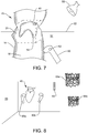
- FIG. 7 shows a VR environment 50 according to an embodiment of the invention.
- the user When using such user interface, the user will find himself in a virtual reality environment, including for example a virtual horizon 52 and a virtual lamp 56. Alternatively, he may find himself in a closed room.
- the visualisation of the dynamic anatomical structure 45 will be floating in the free space in front of the user, thus he will see a three-dimensional visualisation of the dynamic surface model 14, which appears like a transparent vessel having the shape of the left ventricle and possibly the left atrium.
- VOI 40 is locked to the movement of the heart. Since the user will not actually see the outlines of the VOI box 40, the box is indicated in dashed lines.
- a virtual reality object 54 which corresponds to a volume or surface rendering of the image content inside the VOI box 40, namely a volume rendering 54 of the mitral valve 3.
- Both the surface model 14 and the volume rendering 54 will be moving with the heartbeat, wherein the user may start and stop the cine-mode at any point in time within the time period, wherein the time period spanned by the sequence is at least one heartbeat.
- the user may actuate an input tool, namely a virtual reality controller 60.
- This may have buttons 62 which the user may press to start and stop the cine-mode, or to grab and move or tilt the visualisation or virtual reality object 45.
- the user will hold the VR controller 60 in his hand, and ideally would see the controller in front of him at a position corresponding to the real-life hand position.
- FIG. 8 Further advantageous features of the VR environment 50 are illustrated in FIG. 8 .
- the user not only sees the controller 60a and a virtual reality object 45 comprising the volume-rendered VOI and the dynamic surface model, but also further tools or VR objects.
- a tool 64 may be a yardstick or ruler for measuring the dimensions of the anatomical structure, for example the mitral valve.
- VR controllers 60a, 60b held in either hand of the user may be utilised directly for performing measurements on the three-dimensional visualisation 45 by the user selecting points in VR space, wherein the processor calculates the distance in between. Based on such measurements, the best fitting valve may be selected from a library.
- VR environment 50 may contain VR-compatible computer graphical objects 66a, 66b representing implants, in this case mitral valve implants, which can be grabbed by the user with the controllers 60a, 60b and "tried on” the mitral valve represented in the visualisation 45.
- the user can also try out the positions of the valves 66a, 66b, so that he will be able to insert the valve at the correct position during the actual intervention.
- VR objects 66a, 66b are constituted by the elements of the valve implants which are visible in fluoroscopy images, in this case a wire structure.
- Such valve prosthesis may be used in valve-in-valve procedures and are unfolded directly into the old valve in a minimally invasive procedure.
- FIG. 9 illustrates an enlarged view of the VR environment 50, showing the horizon 52 and surface model 14 of the left ventricle. Volume-rendered valve 54 is also shown.
- the user has selected and grabbed a new valve 66 (or rather a VR object corresponding thereto), has placed it inside the three-dimensional visualisation 45 for an initial inspection.
- the new valve is then locked to the movement of the mitral annulus using 3D speckle tracking.
- the remaining LVOT 20 and possible obstructions can be measured and evaluated throughout the cardiac cycle.
- the placement of the VR object corresponding to the valve can be optimised in the dynamic movement. The placement of the valve can be adjusted while simulating the movement within the cardiac cycle.
- FIG. 10 shows a user interface according to a non-VR embodiment of the invention.
- the dynamic visualisation 45 is on a conventional computer screen 70, and the visualisation is merely a rendering on a two-dimensional screen 70.
- the screen may comprise a panel 71 of buttons and sliders allowing the user to tilt, zoom, move or otherwise manipulate visualisation 45.
- it is useful tool to have a volume rendered VOI which is locked to the position of a feature of interest on a dynamic model of a dynamic anatomical structure, such as the beating heart.
- the display may be controlled by a computer 72, such as a PC, including a processor 73 and a hard disc 75.
- the user interface may have input tools such as a keyboard 74 and/or a mouse 76.
- the user interface is a virtual reality interface, as shown in FIG. 11 .
- Such interface is realised by a virtual reality headset 82 worn by a user 80.
- the headset 82 is connected to a computer 72, either through a cable or through wireless connection.
- Such virtual reality headset 82 includes internal displays, separate for each eye, as well as position sensors 84 which track the movement of the head.
- Such headset may also include cameras, in case an augmented reality environment is to be presented.
- the user 80 is holding VR controllers 86 in his hands, wherein the controllers 86 also include position sensors (not shown) as well as buttons or other input elements.
- Such virtual reality controller 86 allows a user to grab and move an object displayed in the virtual reality environment 50.
- the VR headset may for example be an HTC VIVE headset and corresponding VR controllers.
- FIG. 12 shows a flow diagram illustrating the method according to an embodiment of the invention.
- a sequence of three-dimensional medical images showing, e.g., the moving heart is provided, the sequence spanning a time period corresponding to one heartbeat.
- a dynamic model of at least part the heart is provided, for example by fitting a surface model to a part of the anatomical structure, or by generating a surface model by segmentation of one image and feature/speckle tracking.
- the dynamic model is automatically registered with the sequence of images, i.e. the model can be shown at the correct anatomical position on the 3D images.
- the position of an anatomical feature of interest may be determined across the time period, and in particular by means of a reference structure such as the mitral annulus. Further, a volume of interest (VOI) containing the anatomical feature of interest is defined in step 94 within each of the three-dimensional images, so that the VOI follows the position and/or the shape of the anatomical feature of interest across the time period.
- a three-dimensional visualisation environment is provided for visualizing the dynamic anatomical structure across the time period, as described above.
- Such visualisation environment may comprise an input tool in the form of a virtual reality controller, wherein input events from the user may occur in step 98.
- Such input events may then be used to change the visualisation environment shown in step 96, for example by changing the lighting or the threshold of a surface rendering.
- further objects may be shown in the visualisation environment in step 100, e.g. the representation of a valve implant.
Landscapes
- Engineering & Computer Science (AREA)
- Physics & Mathematics (AREA)
- General Physics & Mathematics (AREA)
- Theoretical Computer Science (AREA)
- Computer Vision & Pattern Recognition (AREA)
- Multimedia (AREA)
- Computer Graphics (AREA)
- Health & Medical Sciences (AREA)
- Radiology & Medical Imaging (AREA)
- Software Systems (AREA)
- Computer Hardware Design (AREA)
- General Health & Medical Sciences (AREA)
- Medical Informatics (AREA)
- Nuclear Medicine, Radiotherapy & Molecular Imaging (AREA)
- General Engineering & Computer Science (AREA)
- Quality & Reliability (AREA)
- Apparatus For Radiation Diagnosis (AREA)
- Magnetic Resonance Imaging Apparatus (AREA)
- Ultra Sonic Daignosis Equipment (AREA)
- Image Generation (AREA)
- Processing Or Creating Images (AREA)
- Measuring And Recording Apparatus For Diagnosis (AREA)
Priority Applications (7)
| Application Number | Priority Date | Filing Date | Title |
|---|---|---|---|
| EP19152222.6A EP3683773A1 (en) | 2019-01-17 | 2019-01-17 | Method of visualising a dynamic anatomical structure |
| EP20700144.7A EP3912139B1 (en) | 2019-01-17 | 2020-01-10 | Method of visualising a dynamic anatomical structure |
| PCT/EP2020/050604 WO2020148195A1 (en) | 2019-01-17 | 2020-01-10 | Method of visualising a dynamic anatomical structure |
| US17/423,157 US12217427B2 (en) | 2019-01-17 | 2020-01-10 | Method of visualizing a dynamic anatomical structure |
| CN202080009694.9A CN113302660B (zh) | 2019-01-17 | 2020-01-10 | 对动态解剖结构进行可视化的方法 |
| JP2021537106A JP2022517308A (ja) | 2019-01-17 | 2020-01-10 | 動的解剖学的構造を視覚化する方法 |
| JP2025014437A JP2025084740A (ja) | 2019-01-17 | 2025-01-31 | 動的解剖学的構造を視覚化する方法 |
Applications Claiming Priority (1)
| Application Number | Priority Date | Filing Date | Title |
|---|---|---|---|
| EP19152222.6A EP3683773A1 (en) | 2019-01-17 | 2019-01-17 | Method of visualising a dynamic anatomical structure |
Publications (1)
| Publication Number | Publication Date |
|---|---|
| EP3683773A1 true EP3683773A1 (en) | 2020-07-22 |
Family
ID=65041572
Family Applications (2)
| Application Number | Title | Priority Date | Filing Date |
|---|---|---|---|
| EP19152222.6A Withdrawn EP3683773A1 (en) | 2019-01-17 | 2019-01-17 | Method of visualising a dynamic anatomical structure |
| EP20700144.7A Active EP3912139B1 (en) | 2019-01-17 | 2020-01-10 | Method of visualising a dynamic anatomical structure |
Family Applications After (1)
| Application Number | Title | Priority Date | Filing Date |
|---|---|---|---|
| EP20700144.7A Active EP3912139B1 (en) | 2019-01-17 | 2020-01-10 | Method of visualising a dynamic anatomical structure |
Country Status (5)
| Country | Link |
|---|---|
| US (1) | US12217427B2 (enExample) |
| EP (2) | EP3683773A1 (enExample) |
| JP (2) | JP2022517308A (enExample) |
| CN (1) | CN113302660B (enExample) |
| WO (1) | WO2020148195A1 (enExample) |
Cited By (2)
| Publication number | Priority date | Publication date | Assignee | Title |
|---|---|---|---|---|
| WO2023004489A1 (en) * | 2021-07-30 | 2023-02-02 | Ventripoint Diagnostics Ltd. | System, method and/or computer-readable medium for mapping and displaying anatomical structures in a user-friendly manner |
| EP4538982A1 (en) * | 2023-10-10 | 2025-04-16 | Koninklijke Philips N.V. | Computer implemented method for analysing a heart valve, computer program and system |
Families Citing this family (18)
| Publication number | Priority date | Publication date | Assignee | Title |
|---|---|---|---|---|
| US10210956B2 (en) | 2012-10-24 | 2019-02-19 | Cathworks Ltd. | Diagnostically useful results in real time |
| JP7036742B2 (ja) | 2016-05-16 | 2022-03-15 | キャスワークス リミテッド | 血管評価システム |
| JP7532402B2 (ja) | 2019-04-01 | 2024-08-13 | キャスワークス リミテッド | 血管造影画像選択のための方法および装置 |
| EP4033964B1 (en) | 2019-09-23 | 2025-04-09 | Cathworks Ltd. | Methods, apparatus, and system for synchronization between a three-dimensional vascular model and an imaging device |
| TW202206030A (zh) * | 2020-07-14 | 2022-02-16 | 美商外科劇院股份有限公司 | 用於四維血管造影之系統及方法 |
| EP4309142B1 (en) * | 2021-03-19 | 2025-10-29 | Digital Surgery Limited | Adaptive visualization of contextual targets in surgical video |
| EP4309075A1 (en) * | 2021-03-19 | 2024-01-24 | Digital Surgery Limited | Prediction of structures in surgical data using machine learning |
| US12518879B2 (en) * | 2021-08-24 | 2026-01-06 | Biosense Webster (Israel) Ltd. | Anatomically correct reconstruction of an atrium |
| US12315076B1 (en) | 2021-09-22 | 2025-05-27 | Cathworks Ltd. | Four-dimensional motion analysis of a patient's coronary arteries and myocardial wall |
| KR20240148399A (ko) | 2022-02-10 | 2024-10-11 | 캐스웍스 엘티디. | 기계 학습 기반 센서 분석 및 혈관 트리 분할을 위한 시스템 및 방법 |
| US12309341B2 (en) * | 2022-03-18 | 2025-05-20 | Htc Corporation | Wearable device and control method thereof |
| US11786212B1 (en) * | 2022-12-15 | 2023-10-17 | UAB Ligence | Echocardiogram classification with machine learning |
| CN121942048A (zh) | 2023-08-09 | 2026-04-28 | 凯思沃克斯有限公司 | 针对血管指数测量的增强用户界面和串扰分析 |
| IL326432A (en) | 2023-08-09 | 2026-04-01 | Cathworks Ltd | Coronary artery assessment after PCI |
| CN117789563B (zh) * | 2024-02-23 | 2024-05-31 | 湖南晟医智能科技有限公司 | 基于ai和mr技术虚实融合模拟医学教学方法和系统 |
| US12512196B2 (en) | 2024-06-12 | 2025-12-30 | Cathworks Ltd. | Systems and methods for secure sharing of cardiac assessments using QR codes |
| WO2025265025A1 (en) * | 2024-06-20 | 2025-12-26 | Medtronic, Inc. | Methods of annotating ultrasound views and catheter maneuvers in three dimensions, and providing the user with visual aids and alerts to safely navigate in cardiovascular anatomy |
| CN119359971B (zh) * | 2024-10-10 | 2025-12-09 | 南昌大学第一附属医院 | 一种麻醉穿刺辅助定位方法 |
Citations (6)
| Publication number | Priority date | Publication date | Assignee | Title |
|---|---|---|---|---|
| US20050253841A1 (en) | 2004-05-17 | 2005-11-17 | Stefan Brabec | Volume rendering processing distribution in a graphics processing unit |
| US20080194957A1 (en) * | 2007-02-14 | 2008-08-14 | Ralph Thomas Hoctor | Method and Apparatus for Generating an Ultrasound Image of Moving Objects Using Deformable Models |
| US8103070B2 (en) * | 2007-11-22 | 2012-01-24 | Toshiba Medical Visualization Systems Europe, Limited | Volume rendering apparatus and method |
| US20140052001A1 (en) * | 2012-05-31 | 2014-02-20 | Razvan Ioan Ionasec | Mitral Valve Detection for Transthoracic Echocardiography |
| US20160220311A1 (en) * | 2015-01-29 | 2016-08-04 | Siemens Healthcare Gmbh | Planning and guidance of electrophysiology therapies |
| US20170084023A1 (en) * | 2014-03-21 | 2017-03-23 | Koninklijke Philips N.V. | Image processing apparatus and method for segmenting a region of interest |
Family Cites Families (23)
| Publication number | Priority date | Publication date | Assignee | Title |
|---|---|---|---|---|
| JP2001128982A (ja) | 1999-11-02 | 2001-05-15 | Toshiba Corp | 超音波画像診断装置および画像処理装置 |
| US7042219B2 (en) * | 2004-08-12 | 2006-05-09 | Esaote S.P.A. | Method for determining the condition of an object by magnetic resonance imaging |
| CN101681516A (zh) * | 2007-06-22 | 2010-03-24 | 皇家飞利浦电子股份有限公司 | 标记超声成像系统的2d显示器上的3d体积图像的系统和方法 |
| CN102202576B (zh) * | 2008-10-10 | 2015-04-08 | 皇家飞利浦电子股份有限公司 | 用于为了在微创的x射线引导的介入中减少x射线剂量而产生覆盖经分割的目标结构或病变的减小视场的、具有自动快门适应的血管造影图像采集系统和方法 |
| JP5662326B2 (ja) | 2008-10-23 | 2015-01-28 | コーニンクレッカ フィリップス エヌ ヴェ | インターベンション・ラジオ波焼灼療法またはペースメーカー設置手順における、仮想的な解剖学的構造を豊かにしたリアルタイム2d撮像のための、心臓および/または呼吸同期画像取得システム |
| US8819591B2 (en) * | 2009-10-30 | 2014-08-26 | Accuray Incorporated | Treatment planning in a virtual environment |
| EP2336979B1 (de) | 2009-11-05 | 2014-03-12 | TomTec Imaging Systems GmbH | Verfahren und Vorrichtung zur Segmentierung von medizinischen Bilddaten |
| US20130324833A1 (en) * | 2011-02-24 | 2013-12-05 | Koninklijke Philips N.V. | Non-rigid-body morphing of vessel image using intravascular device shape |
| JP2012217780A (ja) * | 2011-04-14 | 2012-11-12 | Tomtec Imaging Systems Gmbh | 医用画像データをセグメント化するための方法及び装置 |
| WO2013147262A1 (ja) * | 2012-03-30 | 2013-10-03 | 東芝メディカルシステムズ株式会社 | 超音波診断装置、画像処理装置及び画像処理方法 |
| WO2013177520A1 (en) | 2012-05-25 | 2013-11-28 | Surgical Theater LLC | Hybrid image/scene renderer with hands free control |
| JP6396420B2 (ja) * | 2013-04-03 | 2018-09-26 | コーニンクレッカ フィリップス エヌ ヴェKoninklijke Philips N.V. | 3d超音波撮像システム、対応する方法、及び、そのような方法を実施するためのコンピュータプログラム |
| CN103236058B (zh) * | 2013-04-25 | 2016-04-13 | 内蒙古科技大学 | 获取四维心脏图像感兴趣体积的方法 |
| EP2807978A1 (en) * | 2013-05-28 | 2014-12-03 | Universität Bern | Method and system for 3D acquisition of ultrasound images |
| CN105899138B (zh) * | 2014-01-06 | 2019-11-05 | 皇家飞利浦有限公司 | 部署建模 |
| CN106456128B (zh) * | 2014-06-12 | 2020-10-23 | 皇家飞利浦有限公司 | 医学图像处理设备和方法 |
| KR102297346B1 (ko) * | 2014-10-31 | 2021-09-03 | 삼성메디슨 주식회사 | 의료 영상 장치 및 그에 따른 의료 영상을 디스플레이 하는 방법 |
| US10002419B2 (en) * | 2015-03-05 | 2018-06-19 | Siemens Healthcare Gmbh | Direct computation of image-derived biomarkers |
| EP3106096B1 (en) * | 2015-06-12 | 2020-02-19 | Samsung Medison Co., Ltd. | Method and apparatus for displaying ultrasound images |
| CN106600596B (zh) * | 2016-12-21 | 2019-07-12 | 南昌航空大学 | 一种心脏腔室动态显示方法及系统 |
| WO2018186943A1 (en) * | 2017-04-05 | 2018-10-11 | Siemens Medical Solutions Usa, Inc. | Quantitative evaluation of time-varying data |
| US11801114B2 (en) * | 2017-09-11 | 2023-10-31 | Philipp K. Lang | Augmented reality display for vascular and other interventions, compensation for cardiac and respiratory motion |
| US11207133B1 (en) * | 2018-09-10 | 2021-12-28 | David Byron Douglas | Method and apparatus for the interaction of virtual tools and geo-registered tools |
-
2019
- 2019-01-17 EP EP19152222.6A patent/EP3683773A1/en not_active Withdrawn
-
2020
- 2020-01-10 US US17/423,157 patent/US12217427B2/en active Active
- 2020-01-10 CN CN202080009694.9A patent/CN113302660B/zh active Active
- 2020-01-10 JP JP2021537106A patent/JP2022517308A/ja active Pending
- 2020-01-10 EP EP20700144.7A patent/EP3912139B1/en active Active
- 2020-01-10 WO PCT/EP2020/050604 patent/WO2020148195A1/en not_active Ceased
-
2025
- 2025-01-31 JP JP2025014437A patent/JP2025084740A/ja active Pending
Patent Citations (6)
| Publication number | Priority date | Publication date | Assignee | Title |
|---|---|---|---|---|
| US20050253841A1 (en) | 2004-05-17 | 2005-11-17 | Stefan Brabec | Volume rendering processing distribution in a graphics processing unit |
| US20080194957A1 (en) * | 2007-02-14 | 2008-08-14 | Ralph Thomas Hoctor | Method and Apparatus for Generating an Ultrasound Image of Moving Objects Using Deformable Models |
| US8103070B2 (en) * | 2007-11-22 | 2012-01-24 | Toshiba Medical Visualization Systems Europe, Limited | Volume rendering apparatus and method |
| US20140052001A1 (en) * | 2012-05-31 | 2014-02-20 | Razvan Ioan Ionasec | Mitral Valve Detection for Transthoracic Echocardiography |
| US20170084023A1 (en) * | 2014-03-21 | 2017-03-23 | Koninklijke Philips N.V. | Image processing apparatus and method for segmenting a region of interest |
| US20160220311A1 (en) * | 2015-01-29 | 2016-08-04 | Siemens Healthcare Gmbh | Planning and guidance of electrophysiology therapies |
Non-Patent Citations (5)
| Title |
|---|
| CRISTIAN A. LINTE ET AL.: "Virtual reality-enhanced ultrasound guidance: A novel technique for intracardiac interventions", COMPUTER AIDED SURGERY, vol. 13, no. 2, March 2008 (2008-03-01), pages 82 - 94, XP009183965 |
| LIN W ET AL: "VISUALIZATION OF CARDIAC DYNAMICS USING PHYSICS-BASED DEFORMABLE MODEL", VISUAL COMMUNICATIONS AND IMAGE PROCESSING; 20-1-2004 - 20-1-2004; SAN JOSE,, vol. 3976, 15 February 2000 (2000-02-15), pages 210 - 217, XP008019251, ISBN: 978-1-62841-730-2, DOI: 10.1117/12.383043 * |
| LINTE CRISTIAN A ET AL: "Virtual reality-enhanced ultrasound guidance: a novel technique for intracardiac interventions", COMPUTER AIDED SUR, TAYLOR & FRANCIS INC., PHILADELPHIA, PA, US, vol. 13, no. 2, 1 March 2008 (2008-03-01), pages 82 - 94, XP009183965, ISSN: 1092-9088 * |
| SORENSEN T S ET AL: "A new virtual reality approach for planning of cardiac interventions", ARTIFICIAL INTELLIGENCE IN MEDICINE, ELSEVIER, NL, vol. 22, no. 3, 1 June 2001 (2001-06-01), pages 193 - 214, XP002361668, ISSN: 0933-3657, DOI: 10.1016/S0933-3657(00)00109-3 * |
| THOMAS S. SORENSEN ET AL.: "A new virtual reality approach for planning of cardiac interventions", ARTIFICIAL INTELLIGENCE IN MEDICINE, vol. 22, 2001, pages 193 - 2014 |
Cited By (3)
| Publication number | Priority date | Publication date | Assignee | Title |
|---|---|---|---|---|
| WO2023004489A1 (en) * | 2021-07-30 | 2023-02-02 | Ventripoint Diagnostics Ltd. | System, method and/or computer-readable medium for mapping and displaying anatomical structures in a user-friendly manner |
| EP4538982A1 (en) * | 2023-10-10 | 2025-04-16 | Koninklijke Philips N.V. | Computer implemented method for analysing a heart valve, computer program and system |
| WO2025078242A1 (en) | 2023-10-10 | 2025-04-17 | Koninklijke Philips N.V. | Computer implemented method for analysing a heart valve, computer program and system |
Also Published As
| Publication number | Publication date |
|---|---|
| CN113302660A (zh) | 2021-08-24 |
| EP3912139A1 (en) | 2021-11-24 |
| JP2022517308A (ja) | 2022-03-08 |
| US20220130046A1 (en) | 2022-04-28 |
| JP2025084740A (ja) | 2025-06-03 |
| EP3912139B1 (en) | 2025-04-02 |
| WO2020148195A1 (en) | 2020-07-23 |
| US12217427B2 (en) | 2025-02-04 |
| CN113302660B (zh) | 2025-12-12 |
Similar Documents
| Publication | Publication Date | Title |
|---|---|---|
| EP3912139B1 (en) | Method of visualising a dynamic anatomical structure | |
| JP7624975B2 (ja) | 仮想マルチユーザコラボレーションにおいて医用画像データを分析するための方法、コンピュータプログラム、ユーザインターフェース、およびシステム | |
| US8079957B2 (en) | Synchronized three or four-dimensional medical ultrasound imaging and measurements | |
| US20230230321A1 (en) | Extended reality-based user interface add-on, system and method for reviewing 3d or 4d medical image data | |
| US20240394996A1 (en) | Method for analysing 3d medical image data, computer program and 3d medical image data evaluation device | |
| CN117677358A (zh) | 用于手术期间现场x射线荧光透视和c形臂计算机断层扫描成像的立体投影和交叉参考的增强现实系统和方法 | |
| CN102918567A (zh) | 用于执行医疗流程的计算机模拟的系统和方法 | |
| CN116612145A (zh) | 外科手术过程中的光学引导技术 | |
| Sørensen et al. | A new virtual reality approach for planning of cardiac interventions | |
| WO2017180097A1 (en) | Deformable registration of intra and preoperative inputs using generative mixture models and biomechanical deformation | |
| Bruckheimer et al. | Advanced imaging techniques to assist transcatheter congenital heart defects therapies | |
| CN111432718B (zh) | 评估通过解剖学结构的血流阻塞 | |
| RU2808612C2 (ru) | Способ визуализации динамической анатомической структуры | |
| US20160205390A1 (en) | Method for displaying on a screen an object shown in a 3d data set | |
| CN111028326A (zh) | 用于使3d对象的空间表面曲率可视化的方法、系统和介质 | |
| Makhlouf et al. | Biomechanical modeling and pre-operative projection of a human organ using an augmented reality technique during open hepatic surgery | |
| Ford et al. | Heartpad: Real-time visual guidance for cardiac ultrasound | |
| EP4538982A1 (en) | Computer implemented method for analysing a heart valve, computer program and system | |
| Olson et al. | 3D Echocardiography | |
| EP4280164A1 (en) | Computer implemented method for adjusting a morphology of a heart valve model, computer program and system | |
| Lee et al. | Interactive manipulation and visualization of a deformable 3D organ model for medical diagnostic support | |
| Makhachev | Robotic Surgeon-Assistant System for Percutaneous Breast Therapies | |
| Nain | An interactive virtual endoscopy tool with automotive path generation | |
| CN122003702A (zh) | 用于分析心脏瓣膜的计算机实现的方法、计算机程序和系统 | |
| HK1181905A (en) | System and method for performing a computerized simulation of a medical procedure |
Legal Events
| Date | Code | Title | Description |
|---|---|---|---|
| PUAI | Public reference made under article 153(3) epc to a published international application that has entered the european phase |
Free format text: ORIGINAL CODE: 0009012 |
|
| STAA | Information on the status of an ep patent application or granted ep patent |
Free format text: STATUS: THE APPLICATION HAS BEEN PUBLISHED |
|
| AK | Designated contracting states |
Kind code of ref document: A1 Designated state(s): AL AT BE BG CH CY CZ DE DK EE ES FI FR GB GR HR HU IE IS IT LI LT LU LV MC MK MT NL NO PL PT RO RS SE SI SK SM TR |
|
| AX | Request for extension of the european patent |
Extension state: BA ME |
|
| STAA | Information on the status of an ep patent application or granted ep patent |
Free format text: STATUS: THE APPLICATION IS DEEMED TO BE WITHDRAWN |
|
| 18D | Application deemed to be withdrawn |
Effective date: 20210123 |