EP3683390B1 - Concealed hinge for a window or door and window or door equipped with such and method for manufacturing of such hinge - Google Patents
Concealed hinge for a window or door and window or door equipped with such and method for manufacturing of such hinge Download PDFInfo
- Publication number
- EP3683390B1 EP3683390B1 EP19219868.7A EP19219868A EP3683390B1 EP 3683390 B1 EP3683390 B1 EP 3683390B1 EP 19219868 A EP19219868 A EP 19219868A EP 3683390 B1 EP3683390 B1 EP 3683390B1
- Authority
- EP
- European Patent Office
- Prior art keywords
- section
- frame
- wall
- channel
- profile
- Prior art date
- Legal status (The legal status is an assumption and is not a legal conclusion. Google has not performed a legal analysis and makes no representation as to the accuracy of the status listed.)
- Active
Links
Images



Classifications
-
- E—FIXED CONSTRUCTIONS
- E05—LOCKS; KEYS; WINDOW OR DOOR FITTINGS; SAFES
- E05D—HINGES OR SUSPENSION DEVICES FOR DOORS, WINDOWS OR WINGS
- E05D5/00—Construction of single parts, e.g. the parts for attachment
- E05D5/02—Parts for attachment, e.g. flaps
- E05D5/0215—Parts for attachment, e.g. flaps for attachment to profile members or the like
- E05D5/0223—Parts for attachment, e.g. flaps for attachment to profile members or the like with parts, e.g. screws, extending through the profile wall or engaging profile grooves
- E05D5/023—Parts for attachment, e.g. flaps for attachment to profile members or the like with parts, e.g. screws, extending through the profile wall or engaging profile grooves with parts extending through the profile wall
-
- E—FIXED CONSTRUCTIONS
- E05—LOCKS; KEYS; WINDOW OR DOOR FITTINGS; SAFES
- E05D—HINGES OR SUSPENSION DEVICES FOR DOORS, WINDOWS OR WINGS
- E05D5/00—Construction of single parts, e.g. the parts for attachment
- E05D5/02—Parts for attachment, e.g. flaps
- E05D5/06—Bent flaps
-
- E—FIXED CONSTRUCTIONS
- E05—LOCKS; KEYS; WINDOW OR DOOR FITTINGS; SAFES
- E05D—HINGES OR SUSPENSION DEVICES FOR DOORS, WINDOWS OR WINGS
- E05D3/00—Hinges with pins
- E05D3/02—Hinges with pins with one pin
-
- E—FIXED CONSTRUCTIONS
- E05—LOCKS; KEYS; WINDOW OR DOOR FITTINGS; SAFES
- E05D—HINGES OR SUSPENSION DEVICES FOR DOORS, WINDOWS OR WINGS
- E05D5/00—Construction of single parts, e.g. the parts for attachment
- E05D5/02—Parts for attachment, e.g. flaps
- E05D5/0215—Parts for attachment, e.g. flaps for attachment to profile members or the like
- E05D5/0223—Parts for attachment, e.g. flaps for attachment to profile members or the like with parts, e.g. screws, extending through the profile wall or engaging profile grooves
-
- E—FIXED CONSTRUCTIONS
- E05—LOCKS; KEYS; WINDOW OR DOOR FITTINGS; SAFES
- E05Y—INDEXING SCHEME ASSOCIATED WITH SUBCLASSES E05D AND E05F, RELATING TO CONSTRUCTION ELEMENTS, ELECTRIC CONTROL, POWER SUPPLY, POWER SIGNAL OR TRANSMISSION, USER INTERFACES, MOUNTING OR COUPLING, DETAILS, ACCESSORIES, AUXILIARY OPERATIONS NOT OTHERWISE PROVIDED FOR, APPLICATION THEREOF
- E05Y2600/00—Mounting or coupling arrangements for elements provided for in this subclass
- E05Y2600/40—Mounting location; Visibility of the elements
- E05Y2600/41—Concealed
-
- E—FIXED CONSTRUCTIONS
- E05—LOCKS; KEYS; WINDOW OR DOOR FITTINGS; SAFES
- E05Y—INDEXING SCHEME ASSOCIATED WITH SUBCLASSES E05D AND E05F, RELATING TO CONSTRUCTION ELEMENTS, ELECTRIC CONTROL, POWER SUPPLY, POWER SIGNAL OR TRANSMISSION, USER INTERFACES, MOUNTING OR COUPLING, DETAILS, ACCESSORIES, AUXILIARY OPERATIONS NOT OTHERWISE PROVIDED FOR, APPLICATION THEREOF
- E05Y2800/00—Details, accessories and auxiliary operations not otherwise provided for
- E05Y2800/45—Manufacturing
- E05Y2800/455—Extrusion
Definitions
- the present invention relates to a concealed hinge for a door or window, particularly for a door or window with a fixed frame and a leaf that is suspended rotatably around a vertical shaft in the fixed frame by means of one or more concealed hinges.
- the invention relates to a hinge for a door or window the fixed frame of which is made up of hollow profiles.
- the frame profiles and the leaf profiles are provided with a lip with which these profiles overlap in closed condition of the door or window and to which a seal is fitted for the sealing between the frame profiles and the leaf profiles.
- a concealed hinge refers to a hinge that is built into the space between the leaf and the fixed frame, more specifically in the rebate which in a closed door or window is delimited between the opposite walls of the frame and of the leaf and said lips, such that the hinge is not visible when the door or window is closed.
- Known concealed hinges are made from a frame section which is attached on the frame and a leaf section which is attached on the leaf, more specifically on the level of said opposite walls of the frame and of the leaf, whereby both parts are hingeably connected by means of a shaft.
- Hinges are already known whereby the frame section is essentially made as a box-shaped injection moulded body which fits in a pre-fitted recess in the wall of the frame profile facing the rebate, said box-shaped body being open toward the rebate and whereby the leaf section is provided with a curved hook-shaped part which with a closed window or door essentially extends in the box-shaped body and along its free edge is hingeably connected to it by means of a shaft which is attached in the box-shaped body at a depth.
- holes are drilled in the known way on the site in said wall of the frame, in which for example blind rivet nuts or clip anchors are attached with a female thread, in which screws can be screwed for attaching the frame section of the hinge on the frame.
- the box-shaped body is provided at both ends with longitudinal laterally extending flanges which are provided with holes for bolts or screws, which can be screwed in said blind rivet nuts or clip anchors to tighten the flanges against the wall of the frame profile facing the rebate.
- a height adjustment is provided on the known hinges to be able to adjust the height of the leaf in relation to the frame by adjusting the position of the frame section upward.
- several extra components are usually provided which, moreover, are visible when a window or door is open, which is not very aesthetic and moreover may encourage fiddling with the height adjustment, which is not desired of course.
- a disadvantage of the known hinges is that the frame section is manufactured by injection moulding, which makes said component relatively expensive, particularly in view of the high cost of the cast to make said frame section.
- DE20021406U1 discloses an arrangement comprising a frame binding section that is fixed to the frame of a door or window, as well as a wing binding section that is fixed to the wing of the door or window. Vertically, there is hinge section of the binding section that has binding bolts for forming a hinge-like turnable connection for the binding section. There is an adjustment system for adjusting the height level of the wing binding section opposite the frame binding section.
- the invention relates to a concealed hinge for attaching a leaf of a window or door in a fixed frame that is composed of hollow frame profiles, whereby the hinge contains a frame section and a leaf section and whereby the leaf section is intended to be attached to the leaf and is provided with a hook-shaped part for connecting with the frame section and whereby the frame section is intended to be attached to a wall of the frame profile and to this end is provided at each end with a flange and whereby the frame section is provided with a recess for the hook-shaped part of the leaf section which is hingeably connected with the frame section by means of a shaft, wherein the frame section is manufactured from one piece of an extruded basic profile with a first wall and at least a first channel at a distance from said first wall, whereby the basic profile is removed at both its head ends over a length up to said first wall to form said flanges and whereby the first wall
- Such a hinge according to the invention ensures that the frame section can be manufactured relatively easily, quickly and affordably by milling or the like of a one-piece extruded profile.
- the basic profile can also serve for the manufacture of a frame section, suitable for frame profiles with divergent sizes and forms. This results in a greater flexibility in the production to switch between the production of different hinges for different forms of frame profiles, whereby the optimum rotation point can always be set depending on the type of profile.
- the frame section consists of one robust component which benefits the stability of the hinge.
- the shaft of the concealed hinge can be mounted through the remaining sections of the first channel, whereby the shaft can be longitudinally secured at its ends by means of a locknut or other locking means.
- a height adjustment for the leaf is provided in the frame section by adjusting the height of the frame section in the recess of the frame profile in which the frame section is mounted.
- the basic profile which is the basis for the manufacture of the frame section, is preferably provided with a second channel which is removed on the level of the recess in the frame section and in which an adjusting screw is fitted.
- the second channel is positioned such that in mounted condition of the frame section the adjusting screw is located in the recess of the frame profile opposite a rib or other detailing of the frame profile.
- the concealed hinge with the leaf attached thereto rests on the opposite rib or other detailing of the frame profile with the adjusting screw.
- the position of the leaf in the fixed frame can be adjusted upward.
- the basic profile from which the frame section is manufactured possesses a second wall opposite said first wall. Both walls are connected by two connecting walls, a first and a second connecting wall respectively, to delimit an enclosed chamber, which benefits the robustness and stability of the frame section of the hinge.
- one connecting wall can be formed such that it is located in the extension of the hook-shaped part of the leaf section in the open condition of the concealed hinge, such that said connecting wall forms an integrated protective cover for the recess in the frame profile in which the frame section of the hinge is mounted.
- the frame section consists of one robust component, which benefits the stability.
- the hinge comprises the following characteristics.
- the recess in the central section of the first wall extends from one side edge of said first wall to a distance from the opposite side edge of said first wall.
- the length (E) of the recess is slightly longer than the length (F) of the hook-shaped part of the leaf section of the concealed hinge.
- the first wall is a flat wall.
- the shaft of the concealed hinge extends through the remaining sections of the first channel and the shaft is longitudinally secured at its ends by means of a locknut or other locking means.
- Holes are provided in said flanges for screws or bolts for attachment of the flanges against the frame profile.
- the second channel is positioned such that the adjusting screw is located in mounted condition of the frame section in the recess of the frame profile opposite a rib or other detailing of the frame profile.
- the adjusting screw is provided with a seat for a socket head wrench or another tool with which the adjusting screw can be screwed in or out, whereby said end is oriented toward the central recess of the frame section.
- the adjusting screw is provided with a support foot which extends outward relative to the remaining section of the second channel.
- the basic profile from which the frame section is manufactured possesses a second wall opposite said first wall and both walls are connected with each other by two connecting walls, a first connecting wall and a second connecting wall respectively, to delimit an enclosed chamber.
- the connecting walls are located at a distance from the side edges of the first wall of the basic profile from which the frame section of the hinge is manufactured.
- the first channel is provided in the first connecting wall.
- the section of the first connecting wall between the first channel and the first wall is shifted toward the second connecting wall, said section of the first connecting wall being located in the extension of the hook-shaped part of the leaf section in the open condition of the concealed hinge.
- the second channel is located in the enclosed chamber of the basic profile from which the frame section is manufactured.
- the invention also relates to a door or window with a fixed frame in which a leaf is hingeably suspended by means of concealed hinges according to the invention, with a frame section manufactured from a basic profile, whereby the frame section of the concealed hinges is partially fitted in a recess of the frame profile.
- the invention also relates to a method for manufacturing a concealed hinge, as described above, with a frame section and leaf section which are hingeably connected by means of a shaft, whereby the frame section is provided with a recess for a hook-shaped part of the leaf section with which it is hingeably connected and a flange at each end of the frame section for attaching on a frame profile, characterised in that the manufacture of the frame section is based on a length of an extruded basic profile with a first wall and at least a first channel at a distance from said first wall, whereby the method comprises the following steps:
- the method is based on a basic profile which next to the first channel contains another second channel which is removed on the level of said recess and whereby in the remaining section an adjusting screw is screwed at least in one end of the recess.
- the method is also based on a basic profile the second channel of which is positioned such that when the frame section is mounted in a recess of the frame profile provided for this purpose, the adjusting screw is located opposite a rib or other detailing of the frame profile.
- the invention also relates to a concealed hinge for attaching a leaf of a window or door in a fixed frame which is composed of hollow frame profiles with internal ribs, whereby the hinge contains a frame section and a leaf section and whereby the leaf section is intended to be attached to the leaf and is provided with a hook-shaped part to connect with the frame section and whereby the frame section is intended to be attached in a recess of the frame profile, whereby the frame section is provided with an adjusting screw for the height adjustment of the recess which in a mounted condition of the frame section is positioned in the recess opposite a rib of the frame profile and rests on it.
- the adjusting screw is provided at one end with a seat for a socket head wrench or another tool with which the adjusting screw can be screwed in or out, whereby said end is oriented toward the central recess of the frame section.
- the adjusting screw is provided with a support foot at its other end which extends outward relative to the remaining section of the second channel.
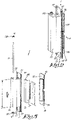
- Figure 1 shows a concealed hinge 1 according to the invention positioned between a frame profile 2 of a fixed frame of a window or door and a leaf profile 3 of a rotatable leaf 6 of the window or of the door 4.
- the frame profile 2 in the shown example is a profile with several hollow chambers which are separated from each other by ribs or partitions 4.
- the walls 5 and 6 of the frame profile 2 and of the leaf profile 3 respectively are oriented toward each other and delimit the rebate or open space between the frame and the leaf in which the hinge 1 is mounted in a concealed way.
- the hinge 1 is composed of a frame section 7 for attaching on the frame profile 2 and a leaf section 8 for attaching on the leaf profile 3, said parts 7 and 8 being hingeably connected by means of a shaft 10.
- the frame section 7 is formed by a box-shaped body 10 with length A and at both ends a flange 11 with screw holes 12 which extend in a parallel way with the longitudinal direction X-X' of the shaft 9.
- the frame profile 2 is provided with a recess 13 with a length B and width C, which is millled to a certain depth from the wall 5, whereby the frame section 7 fits with its body 10 in the recess 13 in such a way that in the mounted condition of the frame section 7 the body 10 is still slideable longitudinally X-X' in the recess 13 for the height adjustment of the hinge 1.
- the length A of the body 10 is less than the length B of the recess 13 and the screw holes 12 are executed as slotted holes.
- the leaf section 9 of the hinge 1 contains a hinge leaf 15 which is attached on said wall 6 of the leaf profile 3 by means of screws (not shown) which are tightened through screw holes 16 in clip anchors 14 in the leaf profile 3.
- the leaf section 9 further contains a hook-shaped part 17 which is attached on the hinge leaf 15 and in the example shown in the figures is executed as a loose component but which alternatively can also be executed in one piece with the hinge leaf 15.
- the hook-shaped part 17 extends in the body 10 of the frame section 7 with its free end and is hingeably connected with it by means of the shaft 9 which is attached at a depth D from the wall 5 in the body 10 and which extends through a shaft passage 18 in the free end of the hook-shaped part 17.
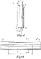
- the special aspect of the invention is that the frame section 7 is manufactured from an extruded basic profile 19, as shown in the figures 5 and 6 , by removing parts 20 and 21 as shown in dashed line in figure 5 , for example by means of milling or other material removing operations.
- the basic profile 19 contains a first, preferably flat wall 22 and an opposite second wall 23 which are connected to each other by two connecting walls, a first connecting wall 24 and a second connecting wall 25 respectively to delimit an enclosed chamber 26.
- the connecting walls 24 and 15 are located at a distance from the side edges 27 of the first wall 22 of the basic profile 19.
- a first channel 28 is provided in a thickened section in the profiling of the first connecting wall 24 which in the profile direction extends at said distance D relative to the first wall 22.
- the extruded basic profile 19 does not contain a channel 28 but only a thickened section in the profiling in which such channel can be provided, for example by drilling.
- the section of the first connecting wall 24 between the thickened section with the first channel 28 and the first wall is shifted to the second connecting wall 25 over a distance, such that the chamber 26 is smaller on the side of the first wall 22 than on the opposite second wall 23.
- a profiling 29 is located in the chamber 26 in which a second channel 30 is formed by extrusion or in which such channel can be fitted by drilling or the like.
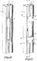
- a section 20 of the basic profile 19 is removed over a length up to said first wall 22 to form said flanges 11, after which the slotted holes 16 are made in these flanges 11.
- a section 21 of the first wall 22 and of the first connecting wall 24 with the first channel 28, as well as of the profiling 29 with the second channel 30, is removed over a length E to form a recess for the hook-shaped part 17 of the leaf section 8 of the hinge 1, said recess extending through the first wall 22 from one side edge 27 of said first wall 22 to a distance from the opposite side edge 27 of said first wall 22, for example up to the second connecting wall 25, whereby at least a section of the second wall 23 and of the second connecting wall 25 remains.
- the length E of the removed section 21 is slightly longer than the length F of the hook-shaped part 17.
- the remaining sections of the first channel 28 form passages for the shaft 9 of the hinge 1 which in a mounted condition extends through said passages and through the shaft passage 18 in the hook-shaped part 17.
- the shaft 9 is secured longitudinally, for example by means of a locknut 32 at each end of the shaft 9 or by any other suitable locking means.
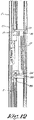
- an adjusting screw 33 is fitted in one of both remaining sections of the profiling 29 with the second channel 30.
- the adjusting screw 33 is provided with a seat 34 for a socket head wrench or other tool with which the adjusting screw can be screwed in or out, whereby the adjusting screw 33 is screwed with said end in the second channel 30 in the direction of the central recess 31.
- the other end of the adjusting screw is provided with a widened support foot 35 which extends outward relative to the remaining section of the second channel 30.
- the second channel 30 is positioned such that the adjusting screw in a mounted condition of the frame section 7 is located opposite said rib 4 or other detailing of the frame profile 3, more specifically in the extension thereof, such that in a mounted condition the frame section 7 rests on said rib with the support foot 35 of the adjusting screw 33.
- Figure 12 shows a situation whereby in relation to the situation of figure 11 the adjusting screw is screwed out downward, such that the frame section 7 is moved upward.
- the invention also relates to a height adjustment as described above with an adjusting screw 33 which rests on a rib 4 of the frame profile 2, whereby it is not necessary for this purpose that the frame section 7 is manufactured from an extruded profile, but for example can also be manufactured as an injection moulded component in which an adjusting screw is screwed longitudinally relative to the frame section 7 or slightly diagonally in relation to said longitudinal direction.
Landscapes
- Engineering & Computer Science (AREA)
- Mechanical Engineering (AREA)
- Hinges (AREA)
Applications Claiming Priority (1)
| Application Number | Priority Date | Filing Date | Title |
|---|---|---|---|
| BE20195025A BE1027039B1 (nl) | 2019-01-16 | 2019-01-16 | Verdektliggend scharnier voor een raam of deur en raam of deur daarmee uitgerust en werkwijze voor het vervaardigen van dergelijk scharnier |
Publications (2)
| Publication Number | Publication Date |
|---|---|
| EP3683390A1 EP3683390A1 (en) | 2020-07-22 |
| EP3683390B1 true EP3683390B1 (en) | 2022-11-09 |
Family
ID=65268700
Family Applications (1)
| Application Number | Title | Priority Date | Filing Date |
|---|---|---|---|
| EP19219868.7A Active EP3683390B1 (en) | 2019-01-16 | 2019-12-27 | Concealed hinge for a window or door and window or door equipped with such and method for manufacturing of such hinge |
Country Status (5)
| Country | Link |
|---|---|
| EP (1) | EP3683390B1 (pl) |
| BE (1) | BE1027039B1 (pl) |
| ES (1) | ES2931956T3 (pl) |
| PL (1) | PL3683390T3 (pl) |
| PT (1) | PT3683390T (pl) |
Families Citing this family (1)
| Publication number | Priority date | Publication date | Assignee | Title |
|---|---|---|---|---|
| WO2026022649A1 (en) | 2024-07-23 | 2026-01-29 | Fapim S.P.A. | Adjustable concealed hinge for windows or doors |
Family Cites Families (2)
| Publication number | Priority date | Publication date | Assignee | Title |
|---|---|---|---|---|
| DE20021406U1 (de) * | 2000-12-18 | 2002-05-02 | Dr. Hahn GmbH & Co. KG, 41189 Mönchengladbach | Bandanordnung für Türen, Fenster u.dgl. |
| PL231737B1 (pl) * | 2016-11-14 | 2019-03-29 | Wala Spolka Z Ograniczona Odpowiedzialnoscia | Układ zawiasowy, a zwłaszcza układ zawiasu ukrytego |
-
2019
- 2019-01-16 BE BE20195025A patent/BE1027039B1/nl not_active IP Right Cessation
- 2019-12-27 PL PL19219868.7T patent/PL3683390T3/pl unknown
- 2019-12-27 EP EP19219868.7A patent/EP3683390B1/en active Active
- 2019-12-27 PT PT192198687T patent/PT3683390T/pt unknown
- 2019-12-27 ES ES19219868T patent/ES2931956T3/es active Active
Also Published As
| Publication number | Publication date |
|---|---|
| PL3683390T3 (pl) | 2023-06-12 |
| ES2931956T3 (es) | 2023-01-05 |
| BE1027039A1 (nl) | 2020-09-01 |
| PT3683390T (pt) | 2022-12-23 |
| EP3683390A1 (en) | 2020-07-22 |
| BE1027039B1 (nl) | 2020-09-07 |
Similar Documents
| Publication | Publication Date | Title |
|---|---|---|
| US6735823B2 (en) | Hinge | |
| US11268294B2 (en) | Snap fit posts for fence panels balustrades and the like | |
| US5655342A (en) | Shimming device for level adjustment and anchoring of window frame in a wall opening | |
| US20040200152A1 (en) | Modular composite sill for threshold | |
| US11952833B1 (en) | Building systems and methods for installing building systems relative to building openings | |
| CA2615322C (en) | Z-bar extension member and assembly | |
| EP2857622B1 (en) | Door jamb for flush in-swing door | |
| US20090077912A1 (en) | Expandable Door Frame and Method of Installation | |
| EP3683390B1 (en) | Concealed hinge for a window or door and window or door equipped with such and method for manufacturing of such hinge | |
| EP1267691B1 (de) | Duschabtrennung | |
| CA2570091C (en) | Hinge attachment system and method | |
| SI1501993T1 (sl) | Razporeditev z vratnim krilom in sarnirji ter tuskabina | |
| US7694388B2 (en) | Adjustable hinge | |
| CA2500148C (en) | Flush mounted louver end cap with tolerance flashing | |
| EP2093362B1 (en) | Method and clamping system for the fixation of a hinge or other metal work on profiles for windows and doors | |
| CZ20009A3 (cs) | Uspořádání prvku kování | |
| PL231737B1 (pl) | Układ zawiasowy, a zwłaszcza układ zawiasu ukrytego | |
| WO2019072429A1 (de) | Drehbeschlag für die verdeckte anordnung an fenster oder türen | |
| EP3004497B1 (en) | Keeps for doors or windows | |
| JPH11141223A (ja) | 調整vレール | |
| CN212898106U (zh) | 一种用于门窗框扇平齐安装的连接型材及框扇平齐门窗 | |
| EP1722057A2 (en) | Adjustable Support Device for Door and Window Hinges | |
| AU2020264327B2 (en) | Adjustable door hinge mechanism | |
| FI124377B (fi) | Säädettävä profiilikarmirakenne | |
| KR200445573Y1 (ko) | 폭조절이 용이한 여닫이식 도어 |
Legal Events
| Date | Code | Title | Description |
|---|---|---|---|
| PUAI | Public reference made under article 153(3) epc to a published international application that has entered the european phase |
Free format text: ORIGINAL CODE: 0009012 |
|
| STAA | Information on the status of an ep patent application or granted ep patent |
Free format text: STATUS: THE APPLICATION HAS BEEN PUBLISHED |
|
| AK | Designated contracting states |
Kind code of ref document: A1 Designated state(s): AL AT BE BG CH CY CZ DE DK EE ES FI FR GB GR HR HU IE IS IT LI LT LU LV MC MK MT NL NO PL PT RO RS SE SI SK SM TR |
|
| AX | Request for extension of the european patent |
Extension state: BA ME |
|
| STAA | Information on the status of an ep patent application or granted ep patent |
Free format text: STATUS: REQUEST FOR EXAMINATION WAS MADE |
|
| 17P | Request for examination filed |
Effective date: 20200908 |
|
| RBV | Designated contracting states (corrected) |
Designated state(s): AL AT BE BG CH CY CZ DE DK EE ES FI FR GB GR HR HU IE IS IT LI LT LU LV MC MK MT NL NO PL PT RO RS SE SI SK SM TR |
|
| RAP1 | Party data changed (applicant data changed or rights of an application transferred) |
Owner name: SOBINCO, NAAMLOZE VENNOOTSCHAP |
|
| RIN1 | Information on inventor provided before grant (corrected) |
Inventor name: VAN PARYS, EMMANUEL |
|
| RIC1 | Information provided on ipc code assigned before grant |
Ipc: E05D 5/06 20060101ALI20220513BHEP Ipc: E05D 5/02 20060101AFI20220513BHEP |
|
| GRAP | Despatch of communication of intention to grant a patent |
Free format text: ORIGINAL CODE: EPIDOSNIGR1 |
|
| STAA | Information on the status of an ep patent application or granted ep patent |
Free format text: STATUS: GRANT OF PATENT IS INTENDED |
|
| INTG | Intention to grant announced |
Effective date: 20220708 |
|
| GRAS | Grant fee paid |
Free format text: ORIGINAL CODE: EPIDOSNIGR3 |
|
| GRAA | (expected) grant |
Free format text: ORIGINAL CODE: 0009210 |
|
| STAA | Information on the status of an ep patent application or granted ep patent |
Free format text: STATUS: THE PATENT HAS BEEN GRANTED |
|
| AK | Designated contracting states |
Kind code of ref document: B1 Designated state(s): AL AT BE BG CH CY CZ DE DK EE ES FI FR GB GR HR HU IE IS IT LI LT LU LV MC MK MT NL NO PL PT RO RS SE SI SK SM TR |
|
| REG | Reference to a national code |
Ref country code: GB Ref legal event code: FG4D |
|
| REG | Reference to a national code |
Ref country code: CH Ref legal event code: EP Ref country code: AT Ref legal event code: REF Ref document number: 1530464 Country of ref document: AT Kind code of ref document: T Effective date: 20221115 |
|
| REG | Reference to a national code |
Ref country code: DE Ref legal event code: R096 Ref document number: 602019021676 Country of ref document: DE |
|
| REG | Reference to a national code |
Ref country code: IE Ref legal event code: FG4D |
|
| REG | Reference to a national code |
Ref country code: NL Ref legal event code: FP |
|
| REG | Reference to a national code |
Ref country code: PT Ref legal event code: SC4A Ref document number: 3683390 Country of ref document: PT Date of ref document: 20221223 Kind code of ref document: T Free format text: AVAILABILITY OF NATIONAL TRANSLATION Effective date: 20221214 |
|
| REG | Reference to a national code |
Ref country code: ES Ref legal event code: FG2A Ref document number: 2931956 Country of ref document: ES Kind code of ref document: T3 Effective date: 20230105 |
|
| REG | Reference to a national code |
Ref country code: LT Ref legal event code: MG9D |
|
| PG25 | Lapsed in a contracting state [announced via postgrant information from national office to epo] |
Ref country code: SE Free format text: LAPSE BECAUSE OF FAILURE TO SUBMIT A TRANSLATION OF THE DESCRIPTION OR TO PAY THE FEE WITHIN THE PRESCRIBED TIME-LIMIT Effective date: 20221109 Ref country code: NO Free format text: LAPSE BECAUSE OF FAILURE TO SUBMIT A TRANSLATION OF THE DESCRIPTION OR TO PAY THE FEE WITHIN THE PRESCRIBED TIME-LIMIT Effective date: 20230209 Ref country code: LT Free format text: LAPSE BECAUSE OF FAILURE TO SUBMIT A TRANSLATION OF THE DESCRIPTION OR TO PAY THE FEE WITHIN THE PRESCRIBED TIME-LIMIT Effective date: 20221109 Ref country code: FI Free format text: LAPSE BECAUSE OF FAILURE TO SUBMIT A TRANSLATION OF THE DESCRIPTION OR TO PAY THE FEE WITHIN THE PRESCRIBED TIME-LIMIT Effective date: 20221109 |
|
| PG25 | Lapsed in a contracting state [announced via postgrant information from national office to epo] |
Ref country code: RS Free format text: LAPSE BECAUSE OF FAILURE TO SUBMIT A TRANSLATION OF THE DESCRIPTION OR TO PAY THE FEE WITHIN THE PRESCRIBED TIME-LIMIT Effective date: 20221109 Ref country code: LV Free format text: LAPSE BECAUSE OF FAILURE TO SUBMIT A TRANSLATION OF THE DESCRIPTION OR TO PAY THE FEE WITHIN THE PRESCRIBED TIME-LIMIT Effective date: 20221109 Ref country code: IS Free format text: LAPSE BECAUSE OF FAILURE TO SUBMIT A TRANSLATION OF THE DESCRIPTION OR TO PAY THE FEE WITHIN THE PRESCRIBED TIME-LIMIT Effective date: 20230309 Ref country code: HR Free format text: LAPSE BECAUSE OF FAILURE TO SUBMIT A TRANSLATION OF THE DESCRIPTION OR TO PAY THE FEE WITHIN THE PRESCRIBED TIME-LIMIT Effective date: 20221109 Ref country code: GR Free format text: LAPSE BECAUSE OF FAILURE TO SUBMIT A TRANSLATION OF THE DESCRIPTION OR TO PAY THE FEE WITHIN THE PRESCRIBED TIME-LIMIT Effective date: 20230210 |
|
| P01 | Opt-out of the competence of the unified patent court (upc) registered |
Effective date: 20230530 |
|
| PG25 | Lapsed in a contracting state [announced via postgrant information from national office to epo] |
Ref country code: SM Free format text: LAPSE BECAUSE OF FAILURE TO SUBMIT A TRANSLATION OF THE DESCRIPTION OR TO PAY THE FEE WITHIN THE PRESCRIBED TIME-LIMIT Effective date: 20221109 Ref country code: RO Free format text: LAPSE BECAUSE OF FAILURE TO SUBMIT A TRANSLATION OF THE DESCRIPTION OR TO PAY THE FEE WITHIN THE PRESCRIBED TIME-LIMIT Effective date: 20221109 Ref country code: IT Free format text: LAPSE BECAUSE OF NON-PAYMENT OF DUE FEES Effective date: 20221227 Ref country code: EE Free format text: LAPSE BECAUSE OF FAILURE TO SUBMIT A TRANSLATION OF THE DESCRIPTION OR TO PAY THE FEE WITHIN THE PRESCRIBED TIME-LIMIT Effective date: 20221109 Ref country code: DK Free format text: LAPSE BECAUSE OF FAILURE TO SUBMIT A TRANSLATION OF THE DESCRIPTION OR TO PAY THE FEE WITHIN THE PRESCRIBED TIME-LIMIT Effective date: 20221109 Ref country code: CZ Free format text: LAPSE BECAUSE OF FAILURE TO SUBMIT A TRANSLATION OF THE DESCRIPTION OR TO PAY THE FEE WITHIN THE PRESCRIBED TIME-LIMIT Effective date: 20221109 |
|
| REG | Reference to a national code |
Ref country code: CH Ref legal event code: PL |
|
| REG | Reference to a national code |
Ref country code: DE Ref legal event code: R097 Ref document number: 602019021676 Country of ref document: DE |
|
| PG25 | Lapsed in a contracting state [announced via postgrant information from national office to epo] |
Ref country code: SK Free format text: LAPSE BECAUSE OF FAILURE TO SUBMIT A TRANSLATION OF THE DESCRIPTION OR TO PAY THE FEE WITHIN THE PRESCRIBED TIME-LIMIT Effective date: 20221109 Ref country code: LU Free format text: LAPSE BECAUSE OF NON-PAYMENT OF DUE FEES Effective date: 20221227 Ref country code: AL Free format text: LAPSE BECAUSE OF FAILURE TO SUBMIT A TRANSLATION OF THE DESCRIPTION OR TO PAY THE FEE WITHIN THE PRESCRIBED TIME-LIMIT Effective date: 20221109 |
|
| PLBE | No opposition filed within time limit |
Free format text: ORIGINAL CODE: 0009261 |
|
| REG | Reference to a national code |
Ref country code: AT Ref legal event code: UEP Ref document number: 1530464 Country of ref document: AT Kind code of ref document: T Effective date: 20221109 |
|
| STAA | Information on the status of an ep patent application or granted ep patent |
Free format text: STATUS: NO OPPOSITION FILED WITHIN TIME LIMIT |
|
| 26N | No opposition filed |
Effective date: 20230810 |
|
| PG25 | Lapsed in a contracting state [announced via postgrant information from national office to epo] |
Ref country code: LI Free format text: LAPSE BECAUSE OF NON-PAYMENT OF DUE FEES Effective date: 20221231 Ref country code: IE Free format text: LAPSE BECAUSE OF NON-PAYMENT OF DUE FEES Effective date: 20221227 Ref country code: CH Free format text: LAPSE BECAUSE OF NON-PAYMENT OF DUE FEES Effective date: 20221231 |
|
| PG25 | Lapsed in a contracting state [announced via postgrant information from national office to epo] |
Ref country code: SI Free format text: LAPSE BECAUSE OF FAILURE TO SUBMIT A TRANSLATION OF THE DESCRIPTION OR TO PAY THE FEE WITHIN THE PRESCRIBED TIME-LIMIT Effective date: 20221109 |
|
| PG25 | Lapsed in a contracting state [announced via postgrant information from national office to epo] |
Ref country code: IT Free format text: LAPSE BECAUSE OF NON-PAYMENT OF DUE FEES Effective date: 20221227 |
|
| PGRI | Patent reinstated in contracting state [announced from national office to epo] |
Ref country code: IT Effective date: 20221231 |
|
| PG25 | Lapsed in a contracting state [announced via postgrant information from national office to epo] |
Ref country code: HU Free format text: LAPSE BECAUSE OF FAILURE TO SUBMIT A TRANSLATION OF THE DESCRIPTION OR TO PAY THE FEE WITHIN THE PRESCRIBED TIME-LIMIT; INVALID AB INITIO Effective date: 20191227 |
|
| PG25 | Lapsed in a contracting state [announced via postgrant information from national office to epo] |
Ref country code: CY Free format text: LAPSE BECAUSE OF FAILURE TO SUBMIT A TRANSLATION OF THE DESCRIPTION OR TO PAY THE FEE WITHIN THE PRESCRIBED TIME-LIMIT Effective date: 20221109 |
|
| PG25 | Lapsed in a contracting state [announced via postgrant information from national office to epo] |
Ref country code: MK Free format text: LAPSE BECAUSE OF FAILURE TO SUBMIT A TRANSLATION OF THE DESCRIPTION OR TO PAY THE FEE WITHIN THE PRESCRIBED TIME-LIMIT Effective date: 20221109 |
|
| PG25 | Lapsed in a contracting state [announced via postgrant information from national office to epo] |
Ref country code: MC Free format text: LAPSE BECAUSE OF FAILURE TO SUBMIT A TRANSLATION OF THE DESCRIPTION OR TO PAY THE FEE WITHIN THE PRESCRIBED TIME-LIMIT Effective date: 20221109 |
|
| PG25 | Lapsed in a contracting state [announced via postgrant information from national office to epo] |
Ref country code: TR Free format text: LAPSE BECAUSE OF FAILURE TO SUBMIT A TRANSLATION OF THE DESCRIPTION OR TO PAY THE FEE WITHIN THE PRESCRIBED TIME-LIMIT Effective date: 20221109 Ref country code: MC Free format text: LAPSE BECAUSE OF FAILURE TO SUBMIT A TRANSLATION OF THE DESCRIPTION OR TO PAY THE FEE WITHIN THE PRESCRIBED TIME-LIMIT Effective date: 20221109 |
|
| PG25 | Lapsed in a contracting state [announced via postgrant information from national office to epo] |
Ref country code: BG Free format text: LAPSE BECAUSE OF FAILURE TO SUBMIT A TRANSLATION OF THE DESCRIPTION OR TO PAY THE FEE WITHIN THE PRESCRIBED TIME-LIMIT Effective date: 20221109 |
|
| PG25 | Lapsed in a contracting state [announced via postgrant information from national office to epo] |
Ref country code: MT Free format text: LAPSE BECAUSE OF FAILURE TO SUBMIT A TRANSLATION OF THE DESCRIPTION OR TO PAY THE FEE WITHIN THE PRESCRIBED TIME-LIMIT Effective date: 20221109 |
|
| PGFP | Annual fee paid to national office [announced via postgrant information from national office to epo] |
Ref country code: AT Payment date: 20241213 Year of fee payment: 6 |
|
| PGFP | Annual fee paid to national office [announced via postgrant information from national office to epo] |
Ref country code: GB Payment date: 20251218 Year of fee payment: 7 |
|
| PGFP | Annual fee paid to national office [announced via postgrant information from national office to epo] |
Ref country code: PT Payment date: 20251222 Year of fee payment: 7 |
|
| PGFP | Annual fee paid to national office [announced via postgrant information from national office to epo] |
Ref country code: FR Payment date: 20251218 Year of fee payment: 7 Ref country code: NL Payment date: 20251217 Year of fee payment: 7 |
|
| PGFP | Annual fee paid to national office [announced via postgrant information from national office to epo] |
Ref country code: BE Payment date: 20251223 Year of fee payment: 7 |
|
| PGFP | Annual fee paid to national office [announced via postgrant information from national office to epo] |
Ref country code: PL Payment date: 20251218 Year of fee payment: 7 |
|
| PGFP | Annual fee paid to national office [announced via postgrant information from national office to epo] |
Ref country code: ES Payment date: 20260119 Year of fee payment: 7 |
|
| PGFP | Annual fee paid to national office [announced via postgrant information from national office to epo] |
Ref country code: DE Payment date: 20251222 Year of fee payment: 7 |
|
| PGFP | Annual fee paid to national office [announced via postgrant information from national office to epo] |
Ref country code: IT Payment date: 20251231 Year of fee payment: 7 |