EP3683162A1 - Rotating stack palette container - Google Patents
Rotating stack palette container Download PDFInfo
- Publication number
- EP3683162A1 EP3683162A1 EP19170269.5A EP19170269A EP3683162A1 EP 3683162 A1 EP3683162 A1 EP 3683162A1 EP 19170269 A EP19170269 A EP 19170269A EP 3683162 A1 EP3683162 A1 EP 3683162A1
- Authority
- EP
- European Patent Office
- Prior art keywords
- container
- pallet container
- edge
- pallet
- runners
- Prior art date
- Legal status (The legal status is an assumption and is not a legal conclusion. Google has not performed a legal analysis and makes no representation as to the accuracy of the status listed.)
- Granted
Links
- 230000002093 peripheral effect Effects 0.000 claims abstract description 4
- XLYOFNOQVPJJNP-UHFFFAOYSA-N water Substances O XLYOFNOQVPJJNP-UHFFFAOYSA-N 0.000 claims description 2
- 238000010521 absorption reaction Methods 0.000 description 10
- 238000007373 indentation Methods 0.000 description 7
- 229920001971 elastomer Polymers 0.000 description 4
- 239000000806 elastomer Substances 0.000 description 4
- 239000000969 carrier Substances 0.000 description 3
- 238000004140 cleaning Methods 0.000 description 2
- 238000010276 construction Methods 0.000 description 2
- 238000001035 drying Methods 0.000 description 2
- 230000005489 elastic deformation Effects 0.000 description 2
- 238000001746 injection moulding Methods 0.000 description 2
- 239000000463 material Substances 0.000 description 2
- 230000035939 shock Effects 0.000 description 2
- 230000002411 adverse Effects 0.000 description 1
- 238000005266 casting Methods 0.000 description 1
- 230000001419 dependent effect Effects 0.000 description 1
- 238000011161 development Methods 0.000 description 1
- 230000018109 developmental process Effects 0.000 description 1
- 238000004519 manufacturing process Methods 0.000 description 1
- 230000007246 mechanism Effects 0.000 description 1
- 238000000034 method Methods 0.000 description 1
- 230000021715 photosynthesis, light harvesting Effects 0.000 description 1
- 238000001175 rotational moulding Methods 0.000 description 1
- 238000000926 separation method Methods 0.000 description 1
- 239000000725 suspension Substances 0.000 description 1
- 230000007704 transition Effects 0.000 description 1
Images


Classifications
-
- B—PERFORMING OPERATIONS; TRANSPORTING
- B65—CONVEYING; PACKING; STORING; HANDLING THIN OR FILAMENTARY MATERIAL
- B65D—CONTAINERS FOR STORAGE OR TRANSPORT OF ARTICLES OR MATERIALS, e.g. BAGS, BARRELS, BOTTLES, BOXES, CANS, CARTONS, CRATES, DRUMS, JARS, TANKS, HOPPERS, FORWARDING CONTAINERS; ACCESSORIES, CLOSURES, OR FITTINGS THEREFOR; PACKAGING ELEMENTS; PACKAGES
- B65D19/00—Pallets or like platforms, with or without side walls, for supporting loads to be lifted or lowered
- B65D19/02—Rigid pallets with side walls, e.g. box pallets
- B65D19/04—Rigid pallets with side walls, e.g. box pallets with bodies moulded or otherwise fabricated in one piece
-
- B—PERFORMING OPERATIONS; TRANSPORTING
- B65—CONVEYING; PACKING; STORING; HANDLING THIN OR FILAMENTARY MATERIAL
- B65D—CONTAINERS FOR STORAGE OR TRANSPORT OF ARTICLES OR MATERIALS, e.g. BAGS, BARRELS, BOTTLES, BOXES, CANS, CARTONS, CRATES, DRUMS, JARS, TANKS, HOPPERS, FORWARDING CONTAINERS; ACCESSORIES, CLOSURES, OR FITTINGS THEREFOR; PACKAGING ELEMENTS; PACKAGES
- B65D19/00—Pallets or like platforms, with or without side walls, for supporting loads to be lifted or lowered
- B65D19/38—Details or accessories
-
- B—PERFORMING OPERATIONS; TRANSPORTING
- B65—CONVEYING; PACKING; STORING; HANDLING THIN OR FILAMENTARY MATERIAL
- B65D—CONTAINERS FOR STORAGE OR TRANSPORT OF ARTICLES OR MATERIALS, e.g. BAGS, BARRELS, BOTTLES, BOXES, CANS, CARTONS, CRATES, DRUMS, JARS, TANKS, HOPPERS, FORWARDING CONTAINERS; ACCESSORIES, CLOSURES, OR FITTINGS THEREFOR; PACKAGING ELEMENTS; PACKAGES
- B65D21/00—Nestable, stackable or joinable containers; Containers of variable capacity
- B65D21/02—Containers specially shaped, or provided with fittings or attachments, to facilitate nesting, stacking, or joining together
- B65D21/0233—Nestable containers
-
- B—PERFORMING OPERATIONS; TRANSPORTING
- B65—CONVEYING; PACKING; STORING; HANDLING THIN OR FILAMENTARY MATERIAL
- B65D—CONTAINERS FOR STORAGE OR TRANSPORT OF ARTICLES OR MATERIALS, e.g. BAGS, BARRELS, BOTTLES, BOXES, CANS, CARTONS, CRATES, DRUMS, JARS, TANKS, HOPPERS, FORWARDING CONTAINERS; ACCESSORIES, CLOSURES, OR FITTINGS THEREFOR; PACKAGING ELEMENTS; PACKAGES
- B65D21/00—Nestable, stackable or joinable containers; Containers of variable capacity
- B65D21/02—Containers specially shaped, or provided with fittings or attachments, to facilitate nesting, stacking, or joining together
- B65D21/04—Open-ended containers shaped to be nested when empty and to be superposed when full
- B65D21/043—Identical stackable containers specially adapted for nesting after rotation around a vertical axis
- B65D21/045—Identical stackable containers specially adapted for nesting after rotation around a vertical axis about 180° only
-
- B—PERFORMING OPERATIONS; TRANSPORTING
- B65—CONVEYING; PACKING; STORING; HANDLING THIN OR FILAMENTARY MATERIAL
- B65D—CONTAINERS FOR STORAGE OR TRANSPORT OF ARTICLES OR MATERIALS, e.g. BAGS, BARRELS, BOTTLES, BOXES, CANS, CARTONS, CRATES, DRUMS, JARS, TANKS, HOPPERS, FORWARDING CONTAINERS; ACCESSORIES, CLOSURES, OR FITTINGS THEREFOR; PACKAGING ELEMENTS; PACKAGES
- B65D2519/00—Pallets or like platforms, with or without side walls, for supporting loads to be lifted or lowered
- B65D2519/00004—Details relating to pallets
- B65D2519/00009—Materials
- B65D2519/00014—Materials for the load supporting surface
- B65D2519/00034—Plastic
-
- B—PERFORMING OPERATIONS; TRANSPORTING
- B65—CONVEYING; PACKING; STORING; HANDLING THIN OR FILAMENTARY MATERIAL
- B65D—CONTAINERS FOR STORAGE OR TRANSPORT OF ARTICLES OR MATERIALS, e.g. BAGS, BARRELS, BOTTLES, BOXES, CANS, CARTONS, CRATES, DRUMS, JARS, TANKS, HOPPERS, FORWARDING CONTAINERS; ACCESSORIES, CLOSURES, OR FITTINGS THEREFOR; PACKAGING ELEMENTS; PACKAGES
- B65D2519/00—Pallets or like platforms, with or without side walls, for supporting loads to be lifted or lowered
- B65D2519/00004—Details relating to pallets
- B65D2519/00009—Materials
- B65D2519/00049—Materials for the base surface
- B65D2519/00069—Plastic
-
- B—PERFORMING OPERATIONS; TRANSPORTING
- B65—CONVEYING; PACKING; STORING; HANDLING THIN OR FILAMENTARY MATERIAL
- B65D—CONTAINERS FOR STORAGE OR TRANSPORT OF ARTICLES OR MATERIALS, e.g. BAGS, BARRELS, BOTTLES, BOXES, CANS, CARTONS, CRATES, DRUMS, JARS, TANKS, HOPPERS, FORWARDING CONTAINERS; ACCESSORIES, CLOSURES, OR FITTINGS THEREFOR; PACKAGING ELEMENTS; PACKAGES
- B65D2519/00—Pallets or like platforms, with or without side walls, for supporting loads to be lifted or lowered
- B65D2519/00004—Details relating to pallets
- B65D2519/00009—Materials
- B65D2519/00154—Materials for the side walls
- B65D2519/00174—Plastic
-
- B—PERFORMING OPERATIONS; TRANSPORTING
- B65—CONVEYING; PACKING; STORING; HANDLING THIN OR FILAMENTARY MATERIAL
- B65D—CONTAINERS FOR STORAGE OR TRANSPORT OF ARTICLES OR MATERIALS, e.g. BAGS, BARRELS, BOTTLES, BOXES, CANS, CARTONS, CRATES, DRUMS, JARS, TANKS, HOPPERS, FORWARDING CONTAINERS; ACCESSORIES, CLOSURES, OR FITTINGS THEREFOR; PACKAGING ELEMENTS; PACKAGES
- B65D2519/00—Pallets or like platforms, with or without side walls, for supporting loads to be lifted or lowered
- B65D2519/00004—Details relating to pallets
- B65D2519/00258—Overall construction
- B65D2519/00263—Overall construction of the pallet
- B65D2519/00268—Overall construction of the pallet made of one piece
-
- B—PERFORMING OPERATIONS; TRANSPORTING
- B65—CONVEYING; PACKING; STORING; HANDLING THIN OR FILAMENTARY MATERIAL
- B65D—CONTAINERS FOR STORAGE OR TRANSPORT OF ARTICLES OR MATERIALS, e.g. BAGS, BARRELS, BOTTLES, BOXES, CANS, CARTONS, CRATES, DRUMS, JARS, TANKS, HOPPERS, FORWARDING CONTAINERS; ACCESSORIES, CLOSURES, OR FITTINGS THEREFOR; PACKAGING ELEMENTS; PACKAGES
- B65D2519/00—Pallets or like platforms, with or without side walls, for supporting loads to be lifted or lowered
- B65D2519/00004—Details relating to pallets
- B65D2519/00258—Overall construction
- B65D2519/00283—Overall construction of the load supporting surface
- B65D2519/00288—Overall construction of the load supporting surface made of one piece
-
- B—PERFORMING OPERATIONS; TRANSPORTING
- B65—CONVEYING; PACKING; STORING; HANDLING THIN OR FILAMENTARY MATERIAL
- B65D—CONTAINERS FOR STORAGE OR TRANSPORT OF ARTICLES OR MATERIALS, e.g. BAGS, BARRELS, BOTTLES, BOXES, CANS, CARTONS, CRATES, DRUMS, JARS, TANKS, HOPPERS, FORWARDING CONTAINERS; ACCESSORIES, CLOSURES, OR FITTINGS THEREFOR; PACKAGING ELEMENTS; PACKAGES
- B65D2519/00—Pallets or like platforms, with or without side walls, for supporting loads to be lifted or lowered
- B65D2519/00004—Details relating to pallets
- B65D2519/00258—Overall construction
- B65D2519/00313—Overall construction of the base surface
- B65D2519/00318—Overall construction of the base surface made of one piece
-
- B—PERFORMING OPERATIONS; TRANSPORTING
- B65—CONVEYING; PACKING; STORING; HANDLING THIN OR FILAMENTARY MATERIAL
- B65D—CONTAINERS FOR STORAGE OR TRANSPORT OF ARTICLES OR MATERIALS, e.g. BAGS, BARRELS, BOTTLES, BOXES, CANS, CARTONS, CRATES, DRUMS, JARS, TANKS, HOPPERS, FORWARDING CONTAINERS; ACCESSORIES, CLOSURES, OR FITTINGS THEREFOR; PACKAGING ELEMENTS; PACKAGES
- B65D2519/00—Pallets or like platforms, with or without side walls, for supporting loads to be lifted or lowered
- B65D2519/00004—Details relating to pallets
- B65D2519/00258—Overall construction
- B65D2519/00313—Overall construction of the base surface
- B65D2519/00328—Overall construction of the base surface shape of the contact surface of the base
- B65D2519/00333—Overall construction of the base surface shape of the contact surface of the base contact surface having a stringer-like shape
-
- B—PERFORMING OPERATIONS; TRANSPORTING
- B65—CONVEYING; PACKING; STORING; HANDLING THIN OR FILAMENTARY MATERIAL
- B65D—CONTAINERS FOR STORAGE OR TRANSPORT OF ARTICLES OR MATERIALS, e.g. BAGS, BARRELS, BOTTLES, BOXES, CANS, CARTONS, CRATES, DRUMS, JARS, TANKS, HOPPERS, FORWARDING CONTAINERS; ACCESSORIES, CLOSURES, OR FITTINGS THEREFOR; PACKAGING ELEMENTS; PACKAGES
- B65D2519/00—Pallets or like platforms, with or without side walls, for supporting loads to be lifted or lowered
- B65D2519/00004—Details relating to pallets
- B65D2519/00258—Overall construction
- B65D2519/00313—Overall construction of the base surface
- B65D2519/00328—Overall construction of the base surface shape of the contact surface of the base
- B65D2519/00338—Overall construction of the base surface shape of the contact surface of the base contact surface having a discrete foot-like shape
-
- B—PERFORMING OPERATIONS; TRANSPORTING
- B65—CONVEYING; PACKING; STORING; HANDLING THIN OR FILAMENTARY MATERIAL
- B65D—CONTAINERS FOR STORAGE OR TRANSPORT OF ARTICLES OR MATERIALS, e.g. BAGS, BARRELS, BOTTLES, BOXES, CANS, CARTONS, CRATES, DRUMS, JARS, TANKS, HOPPERS, FORWARDING CONTAINERS; ACCESSORIES, CLOSURES, OR FITTINGS THEREFOR; PACKAGING ELEMENTS; PACKAGES
- B65D2519/00—Pallets or like platforms, with or without side walls, for supporting loads to be lifted or lowered
- B65D2519/00004—Details relating to pallets
- B65D2519/00258—Overall construction
- B65D2519/00398—Overall construction reinforcements
- B65D2519/00402—Integral, e.g. ribs
- B65D2519/00422—Integral, e.g. ribs on the walls
-
- B—PERFORMING OPERATIONS; TRANSPORTING
- B65—CONVEYING; PACKING; STORING; HANDLING THIN OR FILAMENTARY MATERIAL
- B65D—CONTAINERS FOR STORAGE OR TRANSPORT OF ARTICLES OR MATERIALS, e.g. BAGS, BARRELS, BOTTLES, BOXES, CANS, CARTONS, CRATES, DRUMS, JARS, TANKS, HOPPERS, FORWARDING CONTAINERS; ACCESSORIES, CLOSURES, OR FITTINGS THEREFOR; PACKAGING ELEMENTS; PACKAGES
- B65D2519/00—Pallets or like platforms, with or without side walls, for supporting loads to be lifted or lowered
- B65D2519/00004—Details relating to pallets
- B65D2519/00258—Overall construction
- B65D2519/00492—Overall construction of the side walls
- B65D2519/00497—Overall construction of the side walls whereby at least one side wall is made of one piece
-
- B—PERFORMING OPERATIONS; TRANSPORTING
- B65—CONVEYING; PACKING; STORING; HANDLING THIN OR FILAMENTARY MATERIAL
- B65D—CONTAINERS FOR STORAGE OR TRANSPORT OF ARTICLES OR MATERIALS, e.g. BAGS, BARRELS, BOTTLES, BOXES, CANS, CARTONS, CRATES, DRUMS, JARS, TANKS, HOPPERS, FORWARDING CONTAINERS; ACCESSORIES, CLOSURES, OR FITTINGS THEREFOR; PACKAGING ELEMENTS; PACKAGES
- B65D2519/00—Pallets or like platforms, with or without side walls, for supporting loads to be lifted or lowered
- B65D2519/00004—Details relating to pallets
- B65D2519/00547—Connections
- B65D2519/00577—Connections structures connecting side walls, including corner posts, to each other
- B65D2519/00616—Connections structures connecting side walls, including corner posts, to each other structures not intended to be disassembled
- B65D2519/00621—Connections structures connecting side walls, including corner posts, to each other structures not intended to be disassembled sidewalls directly connected to each other
-
- B—PERFORMING OPERATIONS; TRANSPORTING
- B65—CONVEYING; PACKING; STORING; HANDLING THIN OR FILAMENTARY MATERIAL
- B65D—CONTAINERS FOR STORAGE OR TRANSPORT OF ARTICLES OR MATERIALS, e.g. BAGS, BARRELS, BOTTLES, BOXES, CANS, CARTONS, CRATES, DRUMS, JARS, TANKS, HOPPERS, FORWARDING CONTAINERS; ACCESSORIES, CLOSURES, OR FITTINGS THEREFOR; PACKAGING ELEMENTS; PACKAGES
- B65D2519/00—Pallets or like platforms, with or without side walls, for supporting loads to be lifted or lowered
- B65D2519/00004—Details relating to pallets
- B65D2519/00547—Connections
- B65D2519/00636—Connections structures connecting side walls to the pallet
- B65D2519/00666—Structures not intended to be disassembled
-
- B—PERFORMING OPERATIONS; TRANSPORTING
- B65—CONVEYING; PACKING; STORING; HANDLING THIN OR FILAMENTARY MATERIAL
- B65D—CONTAINERS FOR STORAGE OR TRANSPORT OF ARTICLES OR MATERIALS, e.g. BAGS, BARRELS, BOTTLES, BOXES, CANS, CARTONS, CRATES, DRUMS, JARS, TANKS, HOPPERS, FORWARDING CONTAINERS; ACCESSORIES, CLOSURES, OR FITTINGS THEREFOR; PACKAGING ELEMENTS; PACKAGES
- B65D2519/00—Pallets or like platforms, with or without side walls, for supporting loads to be lifted or lowered
- B65D2519/00004—Details relating to pallets
- B65D2519/00736—Details
- B65D2519/00935—Details with special means for nesting or stacking
- B65D2519/0094—Details with special means for nesting or stacking nestable
-
- B—PERFORMING OPERATIONS; TRANSPORTING
- B65—CONVEYING; PACKING; STORING; HANDLING THIN OR FILAMENTARY MATERIAL
- B65D—CONTAINERS FOR STORAGE OR TRANSPORT OF ARTICLES OR MATERIALS, e.g. BAGS, BARRELS, BOTTLES, BOXES, CANS, CARTONS, CRATES, DRUMS, JARS, TANKS, HOPPERS, FORWARDING CONTAINERS; ACCESSORIES, CLOSURES, OR FITTINGS THEREFOR; PACKAGING ELEMENTS; PACKAGES
- B65D2519/00—Pallets or like platforms, with or without side walls, for supporting loads to be lifted or lowered
- B65D2519/00004—Details relating to pallets
- B65D2519/00736—Details
- B65D2519/00935—Details with special means for nesting or stacking
- B65D2519/00955—Details with special means for nesting or stacking stackable
- B65D2519/00965—Details with special means for nesting or stacking stackable when loaded
- B65D2519/00975—Details with special means for nesting or stacking stackable when loaded through the side walls
Definitions
- the present disclosure relates to an optionally nestable or nested and stackable pallet container, in particular a large load carrier, with a bottom, side walls that expand conically and / or in steps from the bottom to a peripheral container edge, and runners extending below the bottom.
- Rotatable stackable pallet container which has side walls widening towards the container opening, which are designed in such a way that in a relative orientation of two structurally identical unfilled pallet containers, the pallet containers can be nested to reduce the transport volume during empty transport and in another relative orientation there are lower sections of the side walls can support one of the two pallet containers on upper sections of the side walls of the other pallet container and thus stack the pallet containers on one another is made possible.
- the ability to stack and rotate is implemented by means of projections provided on the outside of the side walls and by means of corresponding indentations on the inside of the side walls.
- a pallet container which has a bottom, in particular a rectangular base, and side walls which extend from the bottom to a container edge.
- the container also has a pallet-shaped base part which extends below the base and is adapted for engagement by a fork of a forklift truck or other industrial truck.
- the side walls extend conically and / or in steps widening from the floor upwards to a peripheral container edge.
- runners From the floor extend downwards, in particular two runners that run parallel to one another at least in sections.
- the runners each have at least two engagement openings, which enable an fork of a forklift truck or other industrial truck to engage.
- the bottom and the side walls are shaped in such a way that the pallet container can be nested in an identically orientated identical pallet container and can be stacked on an identical identical pallet container with respect to the pallet container only with respect to a vertical axis of the pallet container or a vertical axis of the identical pallet container.
- the vertical axis of the pallet container extends in particular perpendicular to the floor.
- the vertical axis extends through a center of the floor.
- the pallet container is characterized by the fact that the outer contour of the runners follows the outer contour of the side walls.
- the outer contour of the runners can follow the outer contour of the side walls flush at least in sections.
- the outer contour of the runners can follow the outer contour of the side walls insofar as these outer contours have a geometrically similar shape, at least in sections. That means or it is also possible that a shoulder is formed between the runners and the side walls.
- External contour means in particular the silhouette of a surface facing outwards with respect to the vertical axis of the pallet container or the outline of a surface facing away from the vertical axis of the pallet container in a sectional view parallel to the floor.
- That the outer contour of the runners follows the outer contour of the side walls means in particular that the shape of the outer contour of at least a large part of the runners corresponds to the shape of the outer contour of at least a large part of the side wall adjacent to the runners or is geometrically similar.
- “Flush” means in particular that the shape of the outer contour of the runners in an area immediately adjacent to the side walls corresponds to the shape of the outer contour of the side walls in an area immediately adjacent to the runners.
- the side walls have side wall recesses or indentations which are offset with respect to an adjacent, substantially parallel, section of the corresponding side wall in the direction of a container inner region, that is to say inwards, the
- the inner container area is the area which extends within the side walls above the bottom.
- the side walls have side wall recesses or indentations and not inwardly offset side wall sections.
- the side wall recesses or the indentations restrict the rotational symmetry of the pallet container in such a way that the pallet container can be stacked in the manner of a rotary stacking container in a relative orientation (first relative orientation) on an identical pallet container and in another relative orientation (second relative orientation) in an identical one Pallet container is nestable.
- the pallet container can be brought from the first relative orientation, in which the pallet container and the identical pallet container are oriented in opposite directions, by rotating through 180 ° about its vertical axis into the second relative orientation, in which the pallet container and the identical pallet container are oriented identically.
- first relative orientation sections of the side walls that are not offset inward are located above corresponding side wall recesses or indentations of the structurally identical pallet container.
- second relative orientation the side wall recesses or indentations of the pallet container are embedded in corresponding side wall recesses or indentations of the identical pallet container and are not embedded inwardly offset side wall sections of the pallet container in corresponding non-inwardly offset side wall sections of the identical pallet container.
- the skids each have at least one skid recess on a surface facing away from the interior of the container, which extends transversely, in particular perpendicularly, to the floor and along or at least largely parallel to a longitudinal direction of the respective skid, which is located below one of the side wall recesses.
- the skid recesses and the side wall recesses are each formed at least for the most part in a channel shape.
- the skid recess of one of the skids and the corresponding side wall recess merge. In other words, the skid recess of one of the skids and the corresponding sidewall recess together form a trough-shaped structure.
- the advantage of a pallet container according to the invention is that its orientation can be easily felt by moving one of the runners with one hand along an outer surface.
- the two runners each have an outer edge with at least one s-shaped section.
- each of the outer edges of the runners according to the invention has two rectilinear sections offset parallel to one another and a curved transition section connecting the sections offset parallel to one another.
- the shape of the s-shaped section of a respective runner corresponds to the shape of a cross section parallel to the floor of a part of the adjacent side wall.
- the two rectilinear sections of a respective runner are parallel to an edge of the bottom and one of the rectilinear sections extends closer to the interior of the container than the other rectilinear section.
- the at least two s-shaped sections of the outer edges of the runners can be designed such that they extend in a common (imaginary) plane.
- the orientation of the pallet container can be scanned from two sides in a similar and thus easier than usual manner.
- undersides of the runners facing away from the floor can also extend.
- the lower outer edges of the pallet container are sectionally S-shaped.
- Such an arrangement of the S-shaped sections on an underside of the pallet container makes it possible to scan the pallet container even when the pallet container is raised by an industrial truck.
- the outer edges of the runners can each have two end sections extending in a common (imaginary) straight line.
- the end sections of the respective runner can each be arranged in the region of a corner of the floor.
- Such an arrangement of the end sections of the outer edge of the respective runner makes it possible to ensure a defined tilting in a plane extending perpendicular to the outer edge.
- Recessing recesses can be provided on the circumferential container edge, on which lower support areas of the runners of the identical pallet container are supported when a structurally identical pallet container is stacked on the pallet container and in which the lower support regions of the runners of the identical pallet container are stacked when an identical pallet container is stacked on the pallet container can immerse.
- lower surfaces of the support recesses can extend in a common (imaginary) plane and lower surfaces of the engagement openings can extend in a (other) common (imaginary) plane.
- a depth of the support recesses of the pallet container can be determined such that it is less than or equal to a distance between the common plane of the lower surface of the engagement openings of the pallet container and the common plane of the lower surfaces of the support regions of the runners of the pallet container.
- the pallet container is designed in such a way that the depth of the support recesses and the distance between the common plane of the lower surfaces of the engagement openings and the common plane of the lower surfaces of the support regions of the runners ensure that the lower surfaces of the engagement openings do not lie below an upper edge of Container edges of an identical pallet container are when the pallet container is stacked on the identical pallet container.
- the support recesses and the runners are designed in this way, it is advantageously possible to inadvertently place the pallet container on a filled, identical pallet container in the second relative orientation that is actually intended for nesting by scanning the difference between one of the lower surfaces of the engagement openings of the pallet container and the to recognize the upper edge of the container edge of the filled identical pallet container.
- the edge of the container can be designed to protrude towards the outside of the container.
- the cantilevered container edge can more preferably cantilever at least on two opposite sides by more than 10 mm, so that said cantilevered edge is adapted from one side for engagement of a fork of a lift truck or other industrial truck.
- At least one recessed grip can be provided on an underside of the container edge, which is oriented such that the recessed grip can be reached from below.
- the pallet container nested in an identical pallet container can be manually separated from the identical pallet container.
- At an upper end of the at least one recessed grip at least one opening can be provided, which extends from the recessed grip in the direction away from the inner container region delimited by the floor and the side walls, that is to say to the outside, so that when the pallet container is superimposed on the head Handle recess collected water is at least partially removable to an outside of the pallet container.
- the drying of the pallet container after cleaning can be improved.
- the at least one opening of a respective recessed grip can at least partially extend upwards from the recessed grip.
- the projecting container edge can be designed as a rib structure, in particular as a number of rib wreaths.
- the pallet container according to the invention can be implemented in a lightweight construction.
- the at least one recessed grip can be formed by a U-shaped rib of the rib structure.
- the opening of the U-shaped rib can be directed downwards.
- the U-shaped rib can have an edge facing away from the inner area of the container, to which an outer wall adjoins.
- the outer wall and the U-shaped rib can be designed in such a way that they enclose the recessed grip together.
- At least one of the side walls of the container can have a bumper or damper on its outside, which, viewed in the container height direction, is arranged below the container edge and preferably at a distance therefrom and protrudes from said outside at least to such an extent that it has an (imaginary) plane that between an outer edge of the bottom and an, in particular lower, outer edge of the container edge of which at least one side wall is stretched, tangent or cuts.
- the bumper hits a flat floor in front of the edge of the container when the container is tilted about the associated outer edge of the base.
- the bumper be structurally designed and adapted to at least partially dissipate an impact acting laterally on the container under elastic and / or plastic deformation, ie the structure and / or the choice of material of the bumper can be adapted to, for example, energy occurring in the event of an impact absorb internal friction losses.
- the bumper can be hollow or a clear width can be formed between the bumper and the outer surface of the associated side wall.
- the at least one bumper can be designed in the form of a hollow profile, in particular enclosing a cavity or a clear space together with the shielded side wall.
- the at least one bumper can be arranged in the upper third of the container when viewed in the container height direction, in particular at a distance of 180 to 240 mm from the upper container edge.
- the side walls can extend from the bottom in the direction of the container edge, in particular conically and / or in steps.
- the container cross-section which widens in the height of the container, allows nesting or nesting of several identical containers. With such nestable containers, a bumper is particularly advantageous since the edge is particularly exposed due to the conical shape of the walls.
- the bumper can be designed such that it does not project any further in the direction parallel to the floor than the outer edge of the container edge of the container that is protected / shielded by it Container side in order not to enlarge the external dimensions of the container.
- the bumper can preferably be flush with the outside edge of the container edge or flush with the container in the vertical direction.
- the container can have four side walls and four bumpers can each be arranged in corner regions of the container. In this way, impact forces can be introduced well into the corner regions of a container, which are reinforced anyway.
- the bumpers can preferably be arranged on two mutually opposite side walls of the container. It is advisable to provide bumpers on the longer side walls, for example in the case of containers with an essentially rectangular base area, since the containers tend to tip over the longer bottom edge. In the case of large load carriers, there is often a predetermined engagement direction or engagement sides for forklift trucks and the like. In this case, it is advantageous to arrange the bumpers on side walls facing away from the engagement sides, since a stack of nested containers will usually tip away from the forklift.
- the bumper can have a predetermined impact absorption or crumple section which is designed to dissipate impact energy in the event of an impact with elastic and / or plastic deformation.
- a predetermined impact absorption or crumple section which is designed to dissipate impact energy in the event of an impact with elastic and / or plastic deformation.
- the impact absorption section can be a folded section of the bumper.
- the impact absorption section can be a deliberately introduced predetermined breaking point that dampens the impact force.
- the bumper can have an elastomer section for better shock absorption.
- the bumper can have an elastic spring section, for example an integral one Plastic leaf spring section, be suspended on the container and thus spring-biased arranged relative to the container side wall on the container.
- an elastic spring section for example an integral one Plastic leaf spring section
- the bumper can taper towards the outside of the container or in the direction away from the container. In this way, impact forces can be absorbed at a predetermined, comparatively small-area section of the bumper and distributed in a larger area of the container.
- the bumper can be designed tapering or rounded toward the outside of the container (in the direction facing away from the inside of the container).
- the bumper can have a projection on the outside of the container for the defined introduction of force of impact forces, which protrudes obliquely away from the container and downwards (towards the floor) from the bumper.
- the container can particularly preferably be a large load carrier with a pallet-shaped base part which is adapted for engagement of a fork of a lift truck or other industrial truck.
- large forces act when a stack of containers is tipped over, so that a bumper according to the invention is particularly advantageous.
- the bumper can be designed as a bumper bar arranged on the outside of the associated side wall.
- the container can be made of plastic, in particular in an injection molding or rotomoulding process.
- the container can be made in one piece and the bumper integrally molded on it.
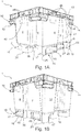
- Figures 1A and 1B show a perspective view of a container 1 according to a preferred embodiment of the invention.
- the container 1 shown is a large plastic load carrier with a pallet-shaped base 2 with recesses or engagement openings 3 for engaging the fork of a forklift truck and four side walls 4, 6, 8, 10.
- the container 1 shown is designed as a nestable container 1, ie the four side walls 4, 6, 8, 10 flare conically towards the container opening in order to enable containers 1 of identical construction to be nested (see, for example, Figure 2A ). More precisely, the container 1 shown is a so-called rotary stacking container, which can either be stacked or nested with an identical container, depending on the relative rotation of the two identical containers to one another.
- the container 1 shown has a projecting container edge 12 which defines its container opening and which is structurally reinforced with a circumferential rib ring.
- the rib structure of the container edge 12 forms recessed areas (not designated here in more detail) which enable one or more containers 1 to be lifted out of a container Allow stacked container 1 by means of a forklift. Especially in such separation operations with forklifts, it is often the case that stacked containers 1 are knocked over.
- the side wall 4 has a side wall recess 5, the side wall 6 has a side wall recess 7, the side wall 8 has side wall recesses 9 and the side wall 10 has a side wall recess 11.
- the bottom 2 has lower outer edges 16, 18, 20 and 22.
- the lower outer edge 16 extends in at a lower end of the side wall 4, the lower outer edge 18 extends in at a lower end of the side wall 6, the lower outer edge 20 extends in at a lower end of the side wall 8 and the lower outer edge 22 in a lower end of the side wall 10.
- the lower outer edge 16 is formed by a runner 17 and the lower outer edge 18 is formed by a runner 19.
- the runner 17 has one skid recess 21 offset inwards.
- the skid 19 has an inwardly offset skid recess 23.
- the two skid recesses 21 and 23 and the two side wall recesses 5 and 7 are each groove-shaped.
- the side wall recesses 5 and 7 extend from the container edge 12 down to the bottom 2.
- the skid recesses 21 and 23 each extend from an upper side of the respective skids 17 and 19 to an underside of the respective skids 17 and 19.
- the side wall recess 5 merges flush into the skid recess 21 so that both together form an inwardly offset, channel-like structure.
- the side wall recess 7 merges flush with the skid recess 23, so that both together form an inwardly offset, channel-shaped structure.
- the skids 17 and 19 each have a curved outer contour.
- the outer edges 16 and 18 are S-shaped due to the skid recesses 5 and 7.
- Respective end sections of the lower outer edges 16 and 18 of the runners 17 and 19, so-called runner outer edge end sections 25 and 27, are designed such that the runner outer edge end sections 25 of the runner 17 extend in a common (imaginary) straight line and that runner outer edge end sections 27 of the runner 19 extend in one extend common (imaginary) straight line.
- the outer edges 16 and 18 of the runners 17 and 19 have S-shaped sections S between the respective skid recess 5 or 7 and the corresponding skid outer edge end sections 25 or 27, more precisely at end regions of the skid recesses 5 or 7.
- the container 1 of the Figures 1A and 1B has in each case in its corner regions horizontally or parallel to the floor projections or ribs 13, which are arranged lower than the circumferential rib rings of the container edge 12 and serve as a stop to limit the depth of the nest when nesting several identical containers 1.
- Support recesses 42 are provided on the top of the container edge 12. Support areas 44 are provided on the underside of the runners 17 and 19. When a structurally identical pallet container is stacked on the pallet container 1, the (lower) contact areas of the runners of the identical pallet container can be immersed in the support recesses 42. Lower surfaces of the support recesses 42 extend in a common plane. Lower surfaces 45 of the engagement openings 3 also extend in a common plane.
- a depth T of the support recesses 42 of the pallet container 1, which extends from the upper side of the container edge 12 to a lower surface of the support recess, is determined such that it is less than or equal to a distance D between the common plane of the lower surface 45 of the engagement openings 3 of the pallet container 1 and the common plane of the lower surfaces of the support areas 44 of the runners 17 and 19 of the pallet container 1.
- two recessed grips 46 are provided on the long side walls 4 and 6 and one recessed grip 46 on the short side walls 8 and 10.
- the recessed grips 46 are oriented such that the recessed grips 46 can be gripped from below.
- each recessed grip 46 is in each case formed by a U-shaped rib of the rib structure of the container edge 12.
- the respective U-shaped rib is oriented so that its opening is directed downwards.
- An outer wall adjoins an edge of the respective U-shaped rib facing away from the interior of the container, which wall, together with the U-shaped rib, encloses the recessed grip 46.
- FIGS. 2A, 2B and 2C illustrate the behavior of a stack of nested large load carriers 1, 1 'when tipping over. It has been determined by the applicant that due to inertia and due to the play between the individual nested containers 1, the lower edge of the projecting container edge 12 'of the bottom container 1' of the stack often forms the first point of impact of such a container stack. This is usually not designed for such loads, which causes the container edge 12 'to break and the container 1' to become unusable.
- Figure 2B shows an end position in which the stack comes to rest on the container edges 12 of the container 1.
- the container edge 12 of the lowermost container 1 of a tipping stack of nested container 1 receives a disproportionately large proportion of the impact force and the exact impact point of impact of the individual containers 1 varies with their position in the container stack. As a result, it is difficult to design the container rim 12 for this load.
- the container 1 according to the preferred embodiment of the invention has a bumper structure or a bumper 14. Like in Figure 2A As can be clearly seen, the bumper 14 'is designed such that it projects beneath the container edge 12' and far enough from the side wall that when a stack of nested containers 1 tips over, the bumper 14 'of the lowest container 1' hits the floor in front of its container edge 12A . The same applies to the containers 1 arranged somewhat further up in the stack.
- the container 1 according to the preferred exemplary embodiment has four such bumpers 14, which are each arranged in corner regions and essentially shield two opposite side walls 4, 6 of the container 1 or from project this (cf. Fig. 1A ).
- the bumper 14 is designed as a bumper structure spaced from the container edge 12 towards the underside of the container and projecting in profile over the side wall 4, 6. More precisely, the bumper protrudes so far from the associated outside of the container that it has an imaginary plane E, which is between the lower outer edge 24, 26, 28, 30 of the projecting container edge 12 and the outer edge 16, 18, 20, 22 of the base 2 and is stretched between the lower outer edge 24, 26 of the projecting container edge 12 and outer runner edge end sections 25, 27 of the base 2.
- the bumper 14 protrudes from the outside of the associated side wall 4, 6, 8, 10 to such an extent that it projects beyond the imaginary plane E and thus when it tilts (with the outer edge 16, 18, 20, 22 of the base 2 as the instantaneous pole) in front of the lower outer edge 24, 26, 28, 30 of the projecting container rim 12 on the floor.
- the bumper 14 is spaced down in the container height direction from the container edge 12 and projects so far in the direction parallel to the floor that it ends flush with a projection A of the outer surface of the container edge 12.
- this serves the purpose that the bumper does not unnecessarily enlarge the external dimensions of the container 1 and, on the other hand, the outer surface of the container edge 12 and the bumper 14 can both serve as support points in a tilted container stack (see also Figure 2C ).
- bumpers 14 A number of preferred exemplary embodiments for bumpers 14 according to the present invention are explained below. All of these embodiments have in common that their overall structure or predetermined impact absorption sections 32 are designed to at least partially absorb or dissipate impacts. Mechanisms for such dissipation of impact energy are mainly internal friction losses in the case of elastic deformation and / or in the plastic deformation of components.
- the bumper 14 shown is designed in its basic structure as a hollow profile and in each case arranged in the corner regions of the container 1.
- Said hollow profile shape includes a cavity or a clear space R between the side wall and the bumper 14.
- the hollow profile-shaped bumper 14 is integrally formed on the container 1 and, due to its overall structure or due to the clear space R enclosed towards the wall, exhibits an elasticity and a defined spring travel / a defined crumple zone for absorbing impact forces.
- the hollow profile shape of the bumper 14 forms a defined butt section 15 at its end (seen from the crimped side wall 4) on the outside of the container, in this case a flattened end section.
- the structure of the bumper 14 (of the hollow profile) widens in the direction towards the container or in the direction towards a container center plane M.
- This has the advantage that impact forces at the impact section 15 can be introduced into the bumper 14 in a defined manner and then distributed over a larger area and introduced into the container 1.
- the expanding hollow profile structure supports a defined elastic deformation of the bumper 14.
- the hollow profile-shaped bumper 14 is molded onto the container 1 in such a way that the hollow profile is open in the direction of the side wall 8, 10 adjacent to the shielded side wall 4, 6. This enables good demoldability during production in a plastic casting process.
- An essentially horizontal or parallel to the floor lower cut of the bumper 14 (or its hollow profile shape) is formed by the rib 13, which also serves to limit the depth of the nest.
- Fig. 5 shows a detailed view of a hollow profile-shaped bumper 14 according to a second embodiment, which is similar in shape and function to the bumper 14 according to the first embodiment.
- the main distinguishing feature of the bumper 14 according to the second embodiment compared to the first embodiment is the rounded or substantially semicircular hollow section section 15 flattened curved butt section 15 according to the embodiment of FIG Figure 4
- the semicircular profile shape creates a higher point of impact in the event of a tipping over and thus an advantageous introduction of force into the hollow profile structure of the bumper 14 which widens in the direction of the container center plane M.
- the bumper 14 shown according to a third exemplary embodiment of the invention has, like the bumper 14 according to the second exemplary embodiment, a round / rounded bumper section 15.
- the bumper 14 has, on the lower half of its semi-circular profile-shaped bumper section 15, a projection 34 which points obliquely away from the interior of the container and points downwards for a defined introduction of force into the bumper 14.
- the semicircular butt section 15 is made above the projection 34 with a reduced material thickness in order to provide a defined predetermined breaking point 35 in this area.
- the bumper 14 according to the in Figure 6 shows a spring section 36 via which it is suspended on the container 1 (here on the container edge 12). Due to the resilient suspension already provided by the spring section 36, the bumper 14 according to the third exemplary embodiment can be designed with a less widening hollow profile structure.
- Fig. 7 shows a fourth embodiment of a bumper 14 according to the invention.
- This has an impact absorption section 38 in the form of a folded section 38. Similar to comparable structures in cars, the folded structure enables a defined deformation with increased energy dissipation per compressed route.
- the folded section 38 is arranged in the horizontally running section or the rib 13 of the hollow-profile-shaped bumper 14 and adjacent to the butt section 15 in order to absorb the impact forces that occur in the event of an impact as directly as possible.
- Fig. 8 shows a fifth preferred embodiment of a bumper 14, which is manufactured in a 2-component injection molding process.
- the butt section 15 of the bumper 14 projecting away from the interior of the container is coated with an elastomer section 40, which absorbs the forces that occur in the event of an impact.
- an elastomer cushion 40 is molded onto the bumper 14 on the outside of the container.
- the impact section 15 thus forms the impact absorption section 32 per se.
Landscapes
- Engineering & Computer Science (AREA)
- Mechanical Engineering (AREA)
- Pallets (AREA)
- Vibration Dampers (AREA)
Abstract
Die vorliegende Erfindung betrifft einen Palettenbehälter (1) mit einem Boden (2), Seitenwänden (4, 6, 8, 10), die sich vom Boden (2) aus nach oben zu einem umlaufenden Behälterrand (12) hin konisch und/oder in Stufen aufweitend erstrecken, und Kufen (17, 19), welche einen Eingriff einer Gabel eines Hubstaplers oder anderen Flurförderzeugs ermöglichen. Der Boden (2) und die Seitenwände (4, 6, 8, 10) sind derart geformt, dass der Palettenbehälter (1) in einen gleich orientierten baugleichen Palettenbehälter nestbar ist und auf einen gegenüber dem Palettenbehälter (1) lediglich bezüglich einer Vertikalachse um 180° verdrehten baugleichen Palettenbehälter stapelbar ist. Die Außenkontur der Kufen folgt bündig der Außenkontur der Seitenwände (4, 6, 8, 10).The invention relates to a pallet container (1) with a bottom (2), side walls (4, 6, 8, 10), which are conical and / or in from the bottom (2) upwards to a peripheral container edge (12) Extending steps and runners (17, 19), which allow an engagement of a fork of a forklift truck or other industrial truck. The bottom (2) and the side walls (4, 6, 8, 10) are shaped in such a way that the pallet container (1) can be nested in an identically oriented pallet container of the same design and on one with respect to the pallet container (1) only with respect to a vertical axis by 180 ° twisted identical pallet container is stackable. The outer contour of the runners follows the outer contour of the side walls (4, 6, 8, 10).
Description
Die vorliegende Offenbarung betrifft einen wahlweise nestbaren bzw. ineinandersetzbaren und stapelbaren Palettenbehälter, insbesondere einen Großladungsträger, mit einem Boden, Seitenwänden, die sich vom Boden aus zu einem umlaufenden Behälterrand konisch und/oder in Stufen erweitern, und sich unterhalb des Bodens erstreckenden Kufen.The present disclosure relates to an optionally nestable or nested and stackable pallet container, in particular a large load carrier, with a bottom, side walls that expand conically and / or in steps from the bottom to a peripheral container edge, and runners extending below the bottom.
Aus
Problem bei dem Palettenbehälter gemäß
Aufgabe der vorliegenden Erfindung ist es vor diesem Hintergrund, einen drehstapelbaren Palettenbehälter bereitzustellen, dessen Handhabbarkeit verbessert ist.Against this background, it is the object of the present invention to provide a pallet container which can be stacked in a rotary manner and whose handling is improved.
Diese Aufgabe wird durch die Merkmale des unabhängigen Anspruchs 1 gelöst. Vorteilhafte Weiterbildungen sind Gegenstand der Unteransprüche.This object is achieved by the features of
Erfindungsgemäß ist ein Palettenbehälter vorgesehen, der einen, insbesondere rechteckförmigen, Boden, und Seitenwände, die sich vom Boden aus zu einem Behälterrand erstrecken aufweist. Insbesondere weist der Behälter auch ein sich unterhalb des Bodens erstreckendes, palettenförmiges, für einen Eingriff einer Gabel eines Hubstaplers oder anderen Flurförderzeugs angepasstes Bodenteil auf.According to the invention, a pallet container is provided which has a bottom, in particular a rectangular base, and side walls which extend from the bottom to a container edge. In particular, the container also has a pallet-shaped base part which extends below the base and is adapted for engagement by a fork of a forklift truck or other industrial truck.
Die Seitenwänden erstrecken sich konisch und/oder in Stufen aufweitend vom Boden aus nach oben zu einem umlaufenden Behälterrand hin.The side walls extend conically and / or in steps widening from the floor upwards to a peripheral container edge.
Vom Boden aus erstrecken sich nach unten, insbesondere zwei zumindest abschnittsweise parallel zueinander verlaufende Kufen. Insbesondere weisen die Kufen jeweils zumindest zwei Eingriffsöffnungen auf, welche einen Eingriff einer Gabel eines Hubstaplers oder anderen Flurförderzeugs ermöglichen.From the floor extend downwards, in particular two runners that run parallel to one another at least in sections. In particular, the runners each have at least two engagement openings, which enable an fork of a forklift truck or other industrial truck to engage.
Der Boden und die Seitenwände sind derart geformt sind, dass der Palettenbehälter in einen gleich orientierten baugleichen Palettenbehälter nestbar ist und auf einen gegenüber dem Palettenbehälter lediglich bezüglich einer Vertikalachse des Palettenbehälters bzw. einer Vertikalachse des baugleichen Palettenbehälters um 180° verdrehten baugleichen Palettenbehälter stapelbar ist.The bottom and the side walls are shaped in such a way that the pallet container can be nested in an identically orientated identical pallet container and can be stacked on an identical identical pallet container with respect to the pallet container only with respect to a vertical axis of the pallet container or a vertical axis of the identical pallet container.
Die Vertikalachse des Palettenbehälters erstreckt sich insbesondere senkrecht zum Boden. Insbesondere erstreckt sich die Vertikalachse durch einen Mittelpunkt des Bodens.The vertical axis of the pallet container extends in particular perpendicular to the floor. In particular, the vertical axis extends through a center of the floor.
Der Palettenbehälter zeichnet sich dadurch aus, dass die Außenkontur der Kufen der Außenkontur der Seitenwände folgt. Insbesondere kann die Außenkontur der Kufen der Außenkontur der Seitenwände zumindest abschnittsweise bündig folgen. Alternativ oder zusätzlich kann die Außenkontur der Kufen der Außenkontur der Seitenwände insofern folgen, als diese Außenkonturen zumindest abschnittsweise geometrisch ähnliche Form aufweisen. Das heißt bzw. dabei ist auch möglich, dass zwischen den Kufen und den Seitenwänden ein Absatz ausgebildet ist.The pallet container is characterized by the fact that the outer contour of the runners follows the outer contour of the side walls. In particular, the outer contour of the runners can follow the outer contour of the side walls flush at least in sections. Alternatively or additionally, the outer contour of the runners can follow the outer contour of the side walls insofar as these outer contours have a geometrically similar shape, at least in sections. That means or it is also possible that a shoulder is formed between the runners and the side walls.
Mit Außenkontur ist insbesondere die Silhouette einer bezüglich der Vertikalachse des Palettenbehälters nach außen gerichteten Fläche bzw. der Umriss einer von der Vertikalachse des Palettenbehälters abgewandten Fläche in einer zum Boden parallelen Schnittansicht gemeint.External contour means in particular the silhouette of a surface facing outwards with respect to the vertical axis of the pallet container or the outline of a surface facing away from the vertical axis of the pallet container in a sectional view parallel to the floor.
"Dass die Außenkontur der Kufen der Außenkontur der Seitenwände folgt" heißt insbesondere, dass die Form der Außenkontur zumindest eines Großteils der Kufen der Form der Außenkontur zumindest eines Großteils der jeweils zur Kufe benachbarten Seitenwand entspricht bzw. im geometrischen Sinne ähnlich ist."That the outer contour of the runners follows the outer contour of the side walls" means in particular that the shape of the outer contour of at least a large part of the runners corresponds to the shape of the outer contour of at least a large part of the side wall adjacent to the runners or is geometrically similar.
"Bündig" heißt insbesondere, dass die Form der Außenkontur der Kufen in einem zu den Seitenwänden unmittelbar benachbarten Bereich der Form der Außenkontur der Seitenwände in einem zu den Kufen unmittelbar benachbarten Bereich entspricht."Flush" means in particular that the shape of the outer contour of the runners in an area immediately adjacent to the side walls corresponds to the shape of the outer contour of the side walls in an area immediately adjacent to the runners.
Anders ausgedrückt weisen die Seitenwände Seitenwandrücksprünge oder Einbuchtungen auf, die bezüglich eines benachbarten, im Wesentlichen parallelen, Abschnitts der entsprechenden Seitenwand in Richtung zu einem Behälterinnenbereich, sprich nach innen, versetzt sind, wobei der Behälterinnenbereich in diesem Zusammenhang der Bereich ist, welcher sich innerhalb der Seitenwände oberhalb des Bodens erstreckt. Anders ausgedrückt weisen die Seitenwände Seitenwandrücksprünge bzw. Einbuchtungen und nicht nach innen versetzte Seitenwandabschnitte auf. Die Seitenwandrücksprünge bzw. die Einbuchtungen schränken die Drehsymmetrie des Palettenbehälters derart ein, dass der Palettenbehälter in der Art eines Drehstapelbehälters in einer relativen Orientierung (erste relative Orientierung) auf einem baugleichen Palettenbehälter stapelbar und in einer anderen relativen Orientierung (zweite relative Orientierung) in einen baugleichen Palettenbehälter nestbar ist. Der Palettenbehälter kann von der erste relativen Orientierung, in welcher der Palettenbehälter und der baugleiche Palettenbehälter gegengleich orientiert sind, durch eine Drehung um 180° um seine Vertikalachse in die zweite relative Orientierung gebracht werden, in welcher der Palettenbehälter und der baugleiche Palettenbehälter gleich orientiert sind. In der ersten relativen Orientierung befinden sich nicht nach innen versetzte Abschnitte der Seitenwände oberhalb entsprechender Seitenwandrücksprünge bzw. Einbuchtungen des baugleichen Palettenbehälters. In der zweiten relativen Orientierung sind die Seitenwandrücksprünge bzw. Einbuchtungen des Palettenbehälters in entsprechenden Seitenwandrücksprüngen bzw. Einbuchtungen des baugleichen Palettenbehälters eingebettet und sind nicht nach innen versetzte Seitenwandabschnitte des Palettenbehälters in entsprechenden nicht nach innen versetzten Seitenwandabschnitten des baugleichen Palettenbehälters eingebettet. Die Kufen weisen jeweils an einer vom Behälterinnenbereich abgewandten, sich quer, insbesondere senkrecht, zum Boden und entlang bzw. zumindest größtenteils parallel zu einer Längserstreckungsrichtung der jeweiligen Kufe erstreckenden Fläche zumindest einen Kufenrücksprung auf, welcher sich unterhalb eines der Seitenwandrücksprünge befindet. Die Kufenrücksprünge und die Seitenwandrücksprünge sind jeweils zumindest größtenteils rinnenförmig ausgebildet. Der Kufenrücksprung einer der Kufen und der entsprechende Seitenwandrücksprung gehen ineinander über. Anders ausgedrückt bilden der Kufenrücksprung einer der Kufen und der entsprechende Seitenwandrücksprung zusammen eine rinnenförmige Struktur.In other words, the side walls have side wall recesses or indentations which are offset with respect to an adjacent, substantially parallel, section of the corresponding side wall in the direction of a container inner region, that is to say inwards, the In this context, the inner container area is the area which extends within the side walls above the bottom. In other words, the side walls have side wall recesses or indentations and not inwardly offset side wall sections. The side wall recesses or the indentations restrict the rotational symmetry of the pallet container in such a way that the pallet container can be stacked in the manner of a rotary stacking container in a relative orientation (first relative orientation) on an identical pallet container and in another relative orientation (second relative orientation) in an identical one Pallet container is nestable. The pallet container can be brought from the first relative orientation, in which the pallet container and the identical pallet container are oriented in opposite directions, by rotating through 180 ° about its vertical axis into the second relative orientation, in which the pallet container and the identical pallet container are oriented identically. In the first relative orientation, sections of the side walls that are not offset inward are located above corresponding side wall recesses or indentations of the structurally identical pallet container. In the second relative orientation, the side wall recesses or indentations of the pallet container are embedded in corresponding side wall recesses or indentations of the identical pallet container and are not embedded inwardly offset side wall sections of the pallet container in corresponding non-inwardly offset side wall sections of the identical pallet container. The skids each have at least one skid recess on a surface facing away from the interior of the container, which extends transversely, in particular perpendicularly, to the floor and along or at least largely parallel to a longitudinal direction of the respective skid, which is located below one of the side wall recesses. The skid recesses and the side wall recesses are each formed at least for the most part in a channel shape. The skid recess of one of the skids and the corresponding side wall recess merge. In other words, the skid recess of one of the skids and the corresponding sidewall recess together form a trough-shaped structure.
Der Vorteil eines erfindungsgemäßen Palettenbehälters ist, dass dessen Orientierung einfach ertastbar ist, indem mit einer Hand entlang einer Außenfläche einer der Kufen gefahren wird.The advantage of a pallet container according to the invention is that its orientation can be easily felt by moving one of the runners with one hand along an outer surface.
Gemäß einem zusätzlichen oder alternativen Aspekt weisen die beiden Kufen jeweils eine Außenkante mit jeweils zumindest einem s-förmigen Abschnitt auf. Anders ausgedrückt weist jede der erfindungsgemäßen Außenkanten der Kufen zwei zueinander parallel versetzte geradlinige Abschnitte und einen die zueinander parallel versetzten Abschnitte verbindenden geschwungenen Übergangsabschnitt auf. Insbesondere entspricht die Form des s-förmigen Abschnitts einer jeweiligen Kufe der Form eines zum Boden parallelen Querschnitts eines Teils der benachbarten Seitenwand. Insbesondere sind die beiden geradlinigen Abschnitte einer jeweiligen Kufe parallel zu einem Rand des Bodens und erstreckt sich einer der geradlinigen Abschnitte näher am Behälterinnenbereich als der andere geradlinige Abschnitt.According to an additional or alternative aspect, the two runners each have an outer edge with at least one s-shaped section. In other words, each of the outer edges of the runners according to the invention has two rectilinear sections offset parallel to one another and a curved transition section connecting the sections offset parallel to one another. In particular, the shape of the s-shaped section of a respective runner corresponds to the shape of a cross section parallel to the floor of a part of the adjacent side wall. In particular, the two rectilinear sections of a respective runner are parallel to an edge of the bottom and one of the rectilinear sections extends closer to the interior of the container than the other rectilinear section.
Durch Vorsehen einer Kante kann das Abtasten der Außenkontur der entsprechenden Kufe in vorteilhafterweise geführt werden.By providing an edge, the scanning of the outer contour of the corresponding runner can advantageously be carried out.
Die zumindest zwei s-förmigen Abschnitte der Außenkanten der Kufen können derart ausgebildet sein, dass sie sich in einer gemeinsamen (imaginären) Ebene erstrecken.The at least two s-shaped sections of the outer edges of the runners can be designed such that they extend in a common (imaginary) plane.
Durch solch eine einheitliche Anordnung der s-förmigen Abschnitte kann die Orientierung des Palettenbehälters von zwei Seiten aus in gleichartiger und damit einfacher denn gewohnter Weise abgetastet werden.With such a uniform arrangement of the S-shaped sections, the orientation of the pallet container can be scanned from two sides in a similar and thus easier than usual manner.
In der gemeinsamen Ebene der zumindest zwei s-förmigen Abschnitte der Außenkanten der Kufen können sich auch sich vom Boden abgewandte Unterseiten der Kufen erstrecken. Anders ausgedrückt sind untere Außenkanten des Palettenbehälters abschnittsweise s-förmig ausgebildet.In the common plane of the at least two s-shaped sections of the outer edges of the runners, undersides of the runners facing away from the floor can also extend. In other words, the lower outer edges of the pallet container are sectionally S-shaped.
Durch solch eine Anordnung der s-förmigen Abschnitte an einer Unterseite des Palettenbehälters ist ein Abtasten des Palettenbehälters auch dann möglich, wenn der Palettenbehälter durch ein Flurförderzeug angehoben ist.Such an arrangement of the S-shaped sections on an underside of the pallet container makes it possible to scan the pallet container even when the pallet container is raised by an industrial truck.
Die Außenkanten der Kufen können jeweils zwei sich in einer gemeinsamen (imaginären) Gerade erstreckende Endabschnitte aufweisen. Insbesondere können die Endabschnitte der jeweiligen Kufe jeweils im Bereich einer Ecke des Bodens angeordnet sein.The outer edges of the runners can each have two end sections extending in a common (imaginary) straight line. In particular, the end sections of the respective runner can each be arranged in the region of a corner of the floor.
Durch solch eine Anordnung der Endabschnitte der Außenkante der jeweiligen Kufe ist es möglich, ein definiertes Kippen in einer sich senkrecht zur Außenkante erstreckenden Ebene zu gewährleisten.Such an arrangement of the end sections of the outer edge of the respective runner makes it possible to ensure a defined tilting in a plane extending perpendicular to the outer edge.
An dem umlaufenden Behälterrand können Auflagevertiefungen vorgesehen sein, auf welchen sich bei einer Stapelung eines baugleichen Palettenbehälters auf den Palettenbehälter untere Auflagebereiche der Kufen des baugleichen Palettenbehälters abstützen und in welche sich bei einer Stapelung eines baugleichen Palettenbehälters auf den Palettenbehälter die unteren Auflagebereiche der Kufen des baugleichen Palettenbehälters eintauchen können. Dabei können sich untere Flächen der Auflagevertiefungen in einer gemeinsamen (imaginären) Ebene erstrecken und können sich untere Flächen der Eingriffsöffnungen in einer (anderen) gemeinsamen (imaginären) Ebene erstrecken. Eine Tiefe der Auflagevertiefungen des Palettenbehälters kann derart bestimmt sein, dass sie kleiner oder gleich einem Abstand zwischen der gemeinsamen Ebene der unteren Fläche der Eingriffsöffnungen des Palettenbehälters und der gemeinsamen Ebene der unteren Flächen der Auflagebereiche der Kufen des Palettenbehälters ist.Recessing recesses can be provided on the circumferential container edge, on which lower support areas of the runners of the identical pallet container are supported when a structurally identical pallet container is stacked on the pallet container and in which the lower support regions of the runners of the identical pallet container are stacked when an identical pallet container is stacked on the pallet container can immerse. In this case, lower surfaces of the support recesses can extend in a common (imaginary) plane and lower surfaces of the engagement openings can extend in a (other) common (imaginary) plane. A depth of the support recesses of the pallet container can be determined such that it is less than or equal to a distance between the common plane of the lower surface of the engagement openings of the pallet container and the common plane of the lower surfaces of the support regions of the runners of the pallet container.
Anders ausgedrückt ist der Palettenbehälter derart ausgebildet, dass die Tiefe der Auflagevertiefungen sowie der Abstand zwischen der gemeinsamen Ebene der unteren Flächen der Eingriffsöffnungen und der gemeinsamen Ebene der unteren Flächen der Auflagebereiche der Kufen gewährleisten, dass sich die unteren Flächen der Eingriffsöffnungen nicht unterhalb einer oberen Kante des Behälterrands eines baugleichen Palettenbehälters befinden, wenn der Palettenbehälter auf den baugleichen Palettenbehälters gestapelt wird.In other words, the pallet container is designed in such a way that the depth of the support recesses and the distance between the common plane of the lower surfaces of the engagement openings and the common plane of the lower surfaces of the support regions of the runners ensure that the lower surfaces of the engagement openings do not lie below an upper edge of Container edges of an identical pallet container are when the pallet container is stacked on the identical pallet container.
Sind die Auflagevertiefungen und die Kufen derart ausgebildet, ist es in vorteilhafter Weise möglich, ein versehentliches Abstellen des Palettenbehälters auf einen gefüllten baugleichen Palettenbehälter in der eigentlich zum Nesten vorgesehene zweiten relativen Orientierung durch Abtasten der Differenz zwischen einer der unteren Flächen der Eingriffsöffnungen des Palettenbehälters und der oberen Kante des Behälterrands des gefüllten baugleichen Palettenbehälters zu erkennen.If the support recesses and the runners are designed in this way, it is advantageously possible to inadvertently place the pallet container on a filled, identical pallet container in the second relative orientation that is actually intended for nesting by scanning the difference between one of the lower surfaces of the engagement openings of the pallet container and the to recognize the upper edge of the container edge of the filled identical pallet container.
Der Behälterrand kann zum Behälteräußeren hin vorkragend ausgebildet sein. Weiter bevorzugt kann der vorkragende Behälterrand zumindest an zwei gegenüberliegenden Seiten um mehr als 10 mm vorkragen, sodass besagter vorkragender Rand von einer Seite für einen Eingriff einer Gabel eines Hubstablers oder anderen Flurförderzeugs angepasst ist.The edge of the container can be designed to protrude towards the outside of the container. The cantilevered container edge can more preferably cantilever at least on two opposite sides by more than 10 mm, so that said cantilevered edge is adapted from one side for engagement of a fork of a lift truck or other industrial truck.
Gemäß einem zusätzlichen oder alternativen Aspekt der Erfindung kann an einer Unterseite des Behälterrands zumindest eine Griffmulde vorgesehen sein, die so orientiert ist, dass von unten in die Griffmulde gegriffen werden kann.According to an additional or alternative aspect of the invention, at least one recessed grip can be provided on an underside of the container edge, which is oriented such that the recessed grip can be reached from below.
Durch Vorsehen der Griffmulden kann der in einen baugleichen Palettenbehälter genestete Palettenbehälter manuell von dem baugleichen Palettenbehälter getrennt werden.By providing the recessed handles, the pallet container nested in an identical pallet container can be manually separated from the identical pallet container.
An einem oberen Ende der zumindest einen Griffmulde kann zumindest eine Öffnung vorgesehen sein, die sich von der Griffmulde aus in Richtung weg von dem durch den Boden und die Seitenwände eingegrenzten Behälterinnenbereich, sprich nach außen, erstreckt, so dass bei einer Kopfüberlagerung des Palettenbehälters in der Griffmulde gesammeltes Wasser zumindest teilweise zu einer Außenseite des Palettenbehälters abführbar ist.At an upper end of the at least one recessed grip, at least one opening can be provided, which extends from the recessed grip in the direction away from the inner container region delimited by the floor and the side walls, that is to say to the outside, so that when the pallet container is superimposed on the head Handle recess collected water is at least partially removable to an outside of the pallet container.
Durch Vorsehen der Öffnungen in den Griffmulden kann die Trocknung des Palettenbehälters nach dem Reinigen verbessert werden.By providing the openings in the recessed grips, the drying of the pallet container after cleaning can be improved.
Die zumindest eine Öffnung einer jeweiligen Griffmulde kann sich von der Griffmulde aus zumindest teilweise auch nach oben erstreckt.The at least one opening of a respective recessed grip can at least partially extend upwards from the recessed grip.
Dadurch kann die Trocknung des Palettenbehälters nach dem Reinigen weiter verbessert werden.This can further improve the drying of the pallet container after cleaning.
Der vorkragende Behälterrand kann als eine Rippenstruktur, insbesondere als eine Anzahl von Rippenkränzen, ausgebildet sein.The projecting container edge can be designed as a rib structure, in particular as a number of rib wreaths.
Durch einen solch ausgebildeten Behälterrand kann der erfindungsgemäße Palettenbehälter in Leichtbauweise umgesetzt sein.With such a container edge, the pallet container according to the invention can be implemented in a lightweight construction.
Die zumindest eine Griffmulde kann durch eine u-förmig verlaufende Rippe der Rippenstruktur gebildet sein. Die Öffnung der u-förmig verlaufenden Rippe kann nach unten gerichtet sein. Die u-förmig verlaufende Rippe kann einen vom Behälterinnenbereich abgewandten Rand aufweisen, an welchen sich eine Außenwand anschließt. Die Außenwand und die u-förmig verlaufende Rippe können derart ausgebildet sein, dass sie zusammen die Griffmulde einhegen.The at least one recessed grip can be formed by a U-shaped rib of the rib structure. The opening of the U-shaped rib can be directed downwards. The U-shaped rib can have an edge facing away from the inner area of the container, to which an outer wall adjoins. The outer wall and the U-shaped rib can be designed in such a way that they enclose the recessed grip together.
Zumindest eine der Seitenwände des Behälters kann an ihrer Außenseite einen Stoßfänger bzw. -dämpfer aufweisen, der in Behälterhöhenrichtung betrachtet unterhalb des Behälterrandes und vorzugsweise von diesem beabstandet angeordnet ist und von besagter Außenseite zumindest so weit vorspringt, dass er eine (imaginäre) Ebene, die zwischen einer Außenkante des Bodens und einer, insbesondere unteren, Außenkante des Behälterrandes der zumindest einen Seitenwand aufgespannt wird, tangiert oder schneidet.At least one of the side walls of the container can have a bumper or damper on its outside, which, viewed in the container height direction, is arranged below the container edge and preferably at a distance therefrom and protrudes from said outside at least to such an extent that it has an (imaginary) plane that between an outer edge of the bottom and an, in particular lower, outer edge of the container edge of which at least one side wall is stretched, tangent or cuts.
Durch eine solche konstruktive Auslegung trifft bei einer Kippbewegung des Behälters um die zugehörigen Außenkante des Bodens der Stoßfänger vor dem Behälterrand auf einem ebenen Boden auf. Zudem kann der Stoßfänger konstruktiv dazu ausgelegt und angepasst sein, einen seitlich auf den Behälter wirkenden Stoß unter elastischer und/oder plastischer Verformung zumindest teilweise zu dissipieren, d.h. der Stoßfänger kann in seiner Struktur und/oder seiner Materialauswahl dazu angepasst sein, bei einem Aufprall auftretende Energien bspw. durch innere Reibungsverluste aufzunehmen.By means of such a design, the bumper hits a flat floor in front of the edge of the container when the container is tilted about the associated outer edge of the base. In addition, the bumper be structurally designed and adapted to at least partially dissipate an impact acting laterally on the container under elastic and / or plastic deformation, ie the structure and / or the choice of material of the bumper can be adapted to, for example, energy occurring in the event of an impact absorb internal friction losses.
Gemäß einem weiter bevorzugten Aspekt der Erfindung kann der Stoßfänger hohl ausgeführt sein oder es kann zwischen Stoßfänger und der Außenfläche der zugehörigen Seitenwand eine lichte Weite ausgebildet sein. Besonders bevorzugt kann der zumindest eine Stoßfänger hohlprofilförmig ausgebildet sein, insbesondere zusammen mit der abgeschirmten Seitenwand einen Hohlraum bzw. einen lichten Raum einschließen. Das Vorsehen eines Hohlraums bzw. eines lichten Raumes zwischen Stoßfänger und der durch diesen abgeschirmten Seitenwand ermöglicht es, einen bestimmten Verformungsweg bzw. eine Knautschzone zu definieren, auf welchem der Stoßfänger sich verformen und somit Aufprallenergie dissipieren kann.According to a further preferred aspect of the invention, the bumper can be hollow or a clear width can be formed between the bumper and the outer surface of the associated side wall. Particularly preferably, the at least one bumper can be designed in the form of a hollow profile, in particular enclosing a cavity or a clear space together with the shielded side wall. The provision of a cavity or a clear space between the bumper and the side wall shielded by it makes it possible to define a specific deformation path or a crumple zone on which the bumper can deform and thus dissipate impact energy.
Gemäß einem weiter bevorzugten Ausführungsbeispiel der Erfindung kann der zumindest eine Stoßfänger in Behälterhöhenrichtung gesehen im oberen Drittel des Behälters angeordnet sein, insbesondere mit einem Abstand von 180 bis 240 mm zum oberen Behälterrand.According to a further preferred exemplary embodiment of the invention, the at least one bumper can be arranged in the upper third of the container when viewed in the container height direction, in particular at a distance of 180 to 240 mm from the upper container edge.
Gemäß einem bevorzugten Ausführungsbeispiel der Erfindung können die Seitenwände sich vom Boden aus in Richtung Behälterrand, insbesondere konisch und/oder in Stufen, aufweitend erstrecken. Der sich in Behälterhöhenrichtung erweiternde Behälterquerschnitt ermöglicht ein Nesten bzw. Ineinanderschachteln mehrerer baugleicher Behälter. Bei solchen nestbaren Behältern ist ein Stoßfänger besonders von Vorteil, da der Rand aufgrund der konischen Form der Wände besonders exponiert ist.According to a preferred embodiment of the invention, the side walls can extend from the bottom in the direction of the container edge, in particular conically and / or in steps. The container cross-section, which widens in the height of the container, allows nesting or nesting of several identical containers. With such nestable containers, a bumper is particularly advantageous since the edge is particularly exposed due to the conical shape of the walls.
Gemäß einer bevorzugten Ausführungsform kann der Stoßfänger so ausgelegt sein, dass er in bodenparalleler Richtung nicht weiter vorspringt als die Außenkante des Behälterrandes der durch ihn geschützten/abgeschirmten Behälterseite, um die Außenmaße des Behälters nicht zu vergrößern. Bevorzugt kann der Stoßfänger nach außen hin bündig mit besagter Außenkante des Behälterrandes abschließen bzw. in Behälterhöhenrichtung fluchtend mit dieser angeordnet sein.According to a preferred embodiment, the bumper can be designed such that it does not project any further in the direction parallel to the floor than the outer edge of the container edge of the container that is protected / shielded by it Container side in order not to enlarge the external dimensions of the container. The bumper can preferably be flush with the outside edge of the container edge or flush with the container in the vertical direction.
Gemäß einer bevorzugten Ausführungsform kann der Behälter vier Seitenwände aufweisen und vier Stoßfänger können jeweils in Eckbereichen des Behälters angeordnet sein. Auf diese Weise können Aufprallkräfte gut in die ohnehin verstärkten Eckbereiche eines Behälters eingeleitet werden.According to a preferred embodiment, the container can have four side walls and four bumpers can each be arranged in corner regions of the container. In this way, impact forces can be introduced well into the corner regions of a container, which are reinforced anyway.
Bevorzugt können die Stoßfänger an zwei einander gegenüberliegenden Seitenwänden des Behälters angeordnet sein. Es bietet sich an, bspw. bei Behältern mit im Wesentlichen rechteckförmiger Grundfläche, Stoßfänger jeweils an den längeren Seitenwänden vorzusehen, da die Behälter eher über die längere Bodenkante kippen. Bei Großladungsträgern gibt es häufig eine vorbestimmte Eingriffsrichtung bzw. Eingriffsseiten für Gabelstapler und dergleichen. In diesem Fall ist es von Vorteil, die Stoßfänger jeweils an von den Eingriffsseiten abgewandten Seitenwänden anzuordnen, da ein Stapel genesteter Behälter meist vom Gabelstapler weg kippen wird.The bumpers can preferably be arranged on two mutually opposite side walls of the container. It is advisable to provide bumpers on the longer side walls, for example in the case of containers with an essentially rectangular base area, since the containers tend to tip over the longer bottom edge. In the case of large load carriers, there is often a predetermined engagement direction or engagement sides for forklift trucks and the like. In this case, it is advantageous to arrange the bumpers on side walls facing away from the engagement sides, since a stack of nested containers will usually tip away from the forklift.
Gemäß einem weiter bevorzugten Aspekt der Erfindung kann der Stoßfänger einen vorbestimmten Prallabsorbtions- oder Knautschabschnitt aufweisen, der dazu ausgebildet ist, Stoßenergie bei einem Aufprall unter elastischer und/oder plastischer Verformung zu dissipieren. Es sind verschiedene Ausführungsformen solcher Prallabsorptionsabschnitte denkbar. Gemäß einem bevorzugten Ausführungsbeispiel kann der Prallabsorptionsabschnitt ein gefalteter Abschnitt des Stoßfängers sein. Gemäß einem weiteren Ausführungsbeispiel kann der Prallabsorptionsabschnitt eine gezielt eingebrachte Sollbruchstelle sein, die die Aufprallwucht dämpft. Gemäß einem weiteren Ausführungsbeispiel kann der Stoßfänger einen Elastomerabschnitt zur besseren Stoßdämpfung aufweisen.According to a further preferred aspect of the invention, the bumper can have a predetermined impact absorption or crumple section which is designed to dissipate impact energy in the event of an impact with elastic and / or plastic deformation. Various embodiments of such impact absorption sections are conceivable. According to a preferred embodiment, the impact absorption section can be a folded section of the bumper. According to a further exemplary embodiment, the impact absorption section can be a deliberately introduced predetermined breaking point that dampens the impact force. According to a further exemplary embodiment, the bumper can have an elastomer section for better shock absorption.
Gemäß einer bevorzugten Ausführungsform der Erfindung kann der Stoßfänger über einen elastischen Federabschnitt, bspw. einen integralen Kunststoff-Blattfederabschnitt, am Behälter aufgehängt sein und somit federvorgespannt relativbeweglich zur Behälterseitenwand am Behälter angeordnet sein.According to a preferred embodiment of the invention, the bumper can have an elastic spring section, for example an integral one Plastic leaf spring section, be suspended on the container and thus spring-biased arranged relative to the container side wall on the container.
Gemäß einem weiter bevorzugten Aspekt kann der Stoßfänger sich zum Behälteräußeren hin bzw. in Richtung vom Behälter weg verjüngen. Auf diese Weise können Aufprallkräfte an einem vorbestimmten vergleichsweise kleinflächigen Abschnitt des Stoßfängers aufgenommen und in eine größere Fläche des Behälters verteilt werden. Gemäß einer bevorzugten Ausführungsform kann der Stoßfänger hierzu zum Behälteräußeren hin (in die vom Behälterinneren abgewandte Richtung) spitz zulaufend oder abgerundet ausgebildet sein.According to a further preferred aspect, the bumper can taper towards the outside of the container or in the direction away from the container. In this way, impact forces can be absorbed at a predetermined, comparatively small-area section of the bumper and distributed in a larger area of the container. According to a preferred embodiment, the bumper can be designed tapering or rounded toward the outside of the container (in the direction facing away from the inside of the container).
Gemäß einer bevorzugten Ausführungsform der Erfindung kann der Stoßfänger behälteraußenseitig einen Vorsprung zur definierten Krafteinleitung von Aufprallkräften aufweisen, der in Richtung schräg vom Behälter weg und nach unten (in Richtung hin zum Boden) vom Stoßfänger vorspringt.According to a preferred embodiment of the invention, the bumper can have a projection on the outside of the container for the defined introduction of force of impact forces, which protrudes obliquely away from the container and downwards (towards the floor) from the bumper.
Besonders bevorzugt kann der Behälter ein Großladungsträger mit einem palettenförmigen, für einen Eingriff einer Gabel eines Hubstablers oder anderen Flurförderzeugs angepassten Bodenteil sein. In solchen Behältern wirken große Kräfte beim Umkippen von Stapeln eineinandergesetzter Behälter, sodass ein erfindungsgemäßer Stoßfänger von besonderem Vorteil ist.The container can particularly preferably be a large load carrier with a pallet-shaped base part which is adapted for engagement of a fork of a lift truck or other industrial truck. In such containers, large forces act when a stack of containers is tipped over, so that a bumper according to the invention is particularly advantageous.
Gemäß einer alternativen Ausführungsform kann der Stoßfänger als ein außenseitig der zugehörigen Seitenwand angeordneter Stoßbügel ausgebildet sein.According to an alternative embodiment, the bumper can be designed as a bumper bar arranged on the outside of the associated side wall.
Gemäß einem weiter bevorzugten Aspekt der Erfindung kann der Behälter aus Kunststoff, insbesondere in einem Spritzguss- oder Rotomouldingverfahren, gefertigt sein. Besonders bevorzugt kann der Behälter stoffeinstückig gefertigt und der Stoßfänger integral an diesem angefromt sein.According to a further preferred aspect of the invention, the container can be made of plastic, in particular in an injection molding or rotomoulding process. Particularly preferably, the container can be made in one piece and the bumper integrally molded on it.
-
Figuren 1A und 1B sind perspektivische Darstellungen eines Behälters gemäß einer ersten Ausführungsform der Erfindung von verschiedenen Seiten;Figures 1A and 1B are perspective views of a container according to a first embodiment of the invention from different sides; -
Figuren 2A, 2B und 2C sind Darstellungen zur Veranschaulichung der Umfallkinematik eines Stapels baugleicher ineinandergesetzter Behälter gemäß dem ersten Ausführungsbeispiel;Figures 2A, 2B and 2C are representations to illustrate the fall kinematics of a stack of identical nested containers according to the first embodiment; -
Fig. 3 ist eine Seitenansicht eines Behälters gemäß der ersten Ausführungsform der Erfindung;Fig. 3 is a side view of a container according to the first embodiment of the invention; -
Fig. 4 ist eine Detailansicht einer ersten Ausführungsform eines Stoßfängers;Fig. 4 is a detailed view of a first embodiment of a bumper; -
Fig. 5 ist eine Detailansicht einer zweiten Ausführungsform eines Stoßfängers;Fig. 5 is a detailed view of a second embodiment of a bumper; -
Fig. 6 ist eine Detailansicht einer dritten Ausführungsform eines Stoßfängers;Fig. 6 is a detailed view of a third embodiment of a bumper; -
Fig. 7 ist eine Detailansicht einer vierten Ausführungsform eines Stoßfängers;Fig. 7 is a detailed view of a fourth embodiment of a bumper; -
Fig. 8 ist eine Detailansicht einer fünften Ausführungsform eines Stoßfängers; undFig. 8 is a detailed view of a fifth embodiment of a bumper; and -
Fig. 9 eine perspektivische Ansicht des Behälters gemäß der ersten Ausführungsform.Fig. 9 a perspective view of the container according to the first embodiment.
Nachstehend werden Ausführungsbeispiele der vorliegenden Offenbarung auf der Basis der zugehörigen Figuren beschrieben.Exemplary embodiments of the present disclosure are described below on the basis of the associated figures.
Der dargestellte Behälter 1 hat einen seine Behälteröffnung definierenden, vorkragenden und mit einem umlaufenden Rippenkranz strukturell verstärkten Behälterrand 12. Durch die Rippenstruktur des Behälterrandes 12 werden (hier nicht näher bezeichnete) zurückgesetzte Bereiche ausgebildet, die das Herausheben eines oder mehrerer Behälter 1 zur Vereinzelung aus einem Stapel ineinandergesetzter Behälter 1 mittels eines Hubstaplers ermöglichen. Gerade bei solchen Vereinzelungs-Operationen mit Hubstaplern kommt es häufig dazu, dass Stapel ineinandergesetzter Behälter 1 umgestoßen werden.The
Die Seitenwand 4 weist einen Seitenwandrücksprung 5, die Seitenwand 6 einen Seitenwandrücksprung 7, die Seitenwand 8 Seitenwandrücksprünge 9 und die Seitenwand 10 einen Seitenwandrücksprung 11 auf.The
Der Boden 2 weist untere Außenkanten 16, 18, 20 und 22 auf. Die untere Außenkante 16 erstreckt sich in an einem unteren Ende der Seitenwand 4, Die untere Außenkante 18 erstreckt sich in an einem unteren Ende der Seitenwand 6, die untere Außenkante 20 erstreckt sich in an einem unteren Ende der Seitenwand 8 und die untere Außenkante 22 erstreckt sich in an einem unteren Ende der Seitenwand 10. Die untere Außenkante 16 ist durch eine Kufe 17 und die untere Außenkante 18 ist durch eine Kufe 19 gebildet. Die Kufe 17 weist einen nach innen versetzten Kufenrücksprung 21 auf. Die Kufe 19 weist einen nach innen versetzten Kufenrücksprung 23 auf. Die beiden Kufenrücksprünge 21 und 23 sowie die beiden Seitenwandrücksprünge 5 und 7 sind jeweils rinnenförmig ausgebildet.The
Die Seitenwandrücksprünge 5 und 7 erstrecken sich vom Behälterrand 12 nach unten bis zum Boden 2. Die Kufenrücksprünge 21 und 23 erstrecken sich jeweils von einer oberen Seite der jeweiligen Kufe 17 bzw. 19 zu einer Unterseite der jeweiligen Kufe 17 bzw. 19. Der Seitenwandrücksprung 5 geht bündig in den Kufenrücksprung 21 über, so dass beide zusammen eine nach innen versetzte, rinnenförmige Struktur bilden. Der Seitenwandrücksprung 7 geht bündig in den Kufenrücksprung 23 über, so dass beide zusammen eine nach innen versetzte, rinnenförmige Struktur bilden.The side wall recesses 5 and 7 extend from the
Durch die Kufenrücksprünge 21 und 23 weisen die Kufen 17 und 19 jeweils eine geschwungen Außenkontur auf. Wie aus den
Der Behälter 1 der
An der Oberseite des Behälterrands 12 sind Auflagevertiefungen 42 vorgesehen. An der Unterseite der Kufen 17 und 19 sind Auflagebereiche 44 vorgesehen. Bei einer Stapelung eines baugleichen Palettenbehälters auf den Palettenbehälter 1 können die (unteren) Auflagebereiche der Kufen des baugleichen Palettenbehälters in die Auflagevertiefungen 42 eintauchen. Untere Flächen der Auflagevertiefungen 42 erstrecken sich in einer gemeinen Ebene. Untere Flächen 45 der Eingriffsöffnungen 3 erstrecken sich auch in einer gemeinsamen Ebene. Eine sich von der Oberseite des Behälterrands 12 bis zu einer unteren Fläche der Auflagevertiefung erstreckende Tiefe T der Auflagevertiefungen 42 des Palettenbehälters 1 ist derart bestimmt, dass sie kleiner oder gleich einem Abstand D zwischen der gemeinsamen Ebene der unteren Fläche 45 der Eingriffsöffnungen 3 des Palettenbehälters 1 und der gemeinsamen Ebene der unteren Flächen der Auflagebereiche 44 der Kufen 17 und 19 des Palettenbehälters 1 ist.Support recesses 42 are provided on the top of the
An einer Unterseite des Behälterrands 12 sind an den langen Seitenwänden 4 und 6 jeweils zwei Griffmulden 46 und an den kurzen Seitenwänden 8 und 10 jeweils eine Griffmulde 46 vorgesehen. Die Griffmulden 46 sind so orientiert, dass jeweils von unten in die Griffmulde 46 gegriffen werden kann.On the underside of the
An oberen Enden der Griffmulden 46 sind jeweils zwei Öffnung 48 vorgesehen, die sich von der Griffmulde aus in Richtung weg von dem durch den Boden 2 und die Seitenwände 4, 6, 8, 10 eingegrenzten Behälterinnenbereich erstrecken. Darüber hinaus sind die Öffnungen 48 derart ausgebildet, dass sie sich jeweils von der Griffmulde 46 auch teilweise nach oben erstreckt. Jede Griffmulde 46 ist jeweils durch eine u-förmig verlaufende Rippe der Rippenstruktur des Behälterrands 12 gebildet. Die jeweilige u-förmig verlaufende Rippe ist so orientiert, dass deren Öffnung nach unten gerichtet ist. An einen vom Behälterinnenbereich abgewandten Rand der jeweiligen u-förmigen Rippe schließt sich eine Außenwand an, die zusammen mit der u-förmig verlaufenden Rippe die Griffmulde 46 einhegt.At the upper ends of the recessed grips 46, two
Die
Wie in
Zusammengefasst bekommt der Behälterrand 12 des untersten Behälters 1 eines umkippenden Stapels ineinandergesetzter Behälter 1 einen unverhältnismäßig großen Anteil der Aufprallwucht ab und der genaue Aufprall-Treffpunkt der einzelnen Behälter 1 variiert mit ihrer Position im Behälterstapel. Folglich ist es nur schwer möglich, den Behälterrand 12 auf diese Belastung auszulegen.In summary, the
Aufgrund der vorstehend beschriebenen Problematik weist der Behälter 1 gemäß dem bevorzugten Ausführungsbeispiel der Erfindung eine Stoßauffangstruktur bzw. einen Stoßfänger 14 auf. Wie bspw. in
Wie bspw. in der Seitenansicht der
Wie in der
Im Folgenden wird eine Reihe bevorzugter Ausführungsbeispiele für Stoßfänger 14 gemäß der vorliegenden Erfindung erläutert. Allen diesen Ausführungsformen gemein ist, dass sie durch ihre Gesamtstruktur oder durch vorbestimmte Prallabsorptionsabschnitte 32 dazu ausgelegt sind, Stöße zumindest teilweise zu absorbieren bzw. zu dissipieren. Mechanismen für eine solche Dissipation von Stoßenergie sind hauptsächlich innere Reibungsverluste bei elastischer Verformung und/oder bei der plastische Deformation von Bauteilen.A number of preferred exemplary embodiments for
Der in den
Der hohlprofilförmige Stoßfänger 14 ist derart an den Behälter 1 angeformt, dass das Hohlprofil in Richtung der zur abgeschirmten Seitenwand 4, 6 angrenzenden Seitenwand 8, 10 offen ist. Dies ermöglicht eine gute Entformbarkeit bei der Fertigung in einem Kunststoff-Gussverfahren. Ein im Wesentlichen horizontal bzw. bodenparallel verlaufender unterer Anschnitt des Stoßfängers 14 (bzw. dessen Hohlprofilform) wird durch die Rippe 13 ausgebildet, die auch zur Begrenzung der Nesttiefe dient.The hollow profile-shaped
Der in
- 11
- GroßladungsträgerLarge load carriers
- 22nd
- Bodenground
- 33rd
- Ausnehmung bzw. EingriffsöffnungRecess or engagement opening
- 4, 6, 8, 104, 6, 8, 10
- SeitenwandSide wall
- 5, 7, 9, 115, 7, 9, 11
- SeitenwandrücksprungSidewall recess
- 1212th
- BehälterrandContainer rim
- 1313
- Rippe für Stapler-Eingriffsflächen bzw. Unterseite des StoßfängersRib for forklift engagement surfaces or underside of the bumper
- 1414
- StoßfängerBumpers
- 1515
- StoßabschnittButt section
- 16, 18, 20, 2216, 18, 20, 22
- Außenkante des BodensOutside edge of the floor
- 17, 1917, 19
- KufeRunners
- 21, 2321, 23
- KufenrücksprungSkid return
- 24, 26, 28, 3024, 26, 28, 30
- (untere) Außenkante des Behälterrandes(lower) outer edge of the container edge
- 25, 2725, 27
- KufenaußenkantenendabschnittSkid outer edge end section
- 3232
- PrallabsorptionsabschnittImpact absorption section
- 3434
- Vorsprunghead Start
- 3535
- SollbruchstellePredetermined breaking point
- 3636
- FederabschnittSpring section
- 3838
- gefalteter Abschnittfolded section
- 4040
- ElastomerabschnittElastomer section
- 4242
- AuflagevertiefungEdition deepening
- 4444
- AuflagebereicheSupport areas
- 4545
- untere Fläche der Eingriffsöffnunglower surface of the engagement opening
- 4646
- GriffmuldeRecessed grip
- AA
- Projektion der AußenflächeProjection of the outside surface
- DD
- Abstand zwischen der gemeinsamen Ebene der unteren Fläche der Eingriffsöffnungen und der gemeinsamen Ebene der unteren Flächen der AuflagebereicheDistance between the common plane of the lower surface of the engagement openings and the common plane of the lower surface of the support areas
- EE
- Ebenelevel
- MM
- BehältermittelebeneContainer middle level
- RR
- lichter Raumclear space
- SS
- s-förmiger AbschnittS-shaped section
- TT
- Tiefe der AuflagevertiefungDepth of the support recess
Claims (15)
einem Boden (2),
Seitenwänden (4, 6, 8, 10), die sich vom Boden (2) aus nach oben zu einem umlaufenden Behälterrand (12) hin konisch und/oder in Stufen aufweitend erstrecken, und
Kufen (17, 19), welche einen Eingriff einer Gabel eines Hubstaplers oder anderen Flurförderzeugs unterhalb des Bodens (2) ermöglichen, wobei der Boden (2) und die Seitenwände (4, 6, 8, 10) derart geformt sind, dass der Palettenbehälter (1) in einen gleich orientierten baugleichen Palettenbehälter nestbar ist und auf einen gegenüber dem Palettenbehälter (1) lediglich bezüglich einer Vertikalachse um 180° verdrehten baugleichen Palettenbehälter stapelbar ist,
dadurch gekennzeichnet, dass
die Außenkontur der Kufen der Außenkontur der Seitenwände (4, 6, 8, 10) folgt.Pallet container (1) with
a floor (2),
Side walls (4, 6, 8, 10), which extend conically and / or widening in steps from the bottom (2) upwards to a peripheral container edge (12), and
Skids (17, 19) which enable a fork of a forklift truck or other industrial truck to engage below the base (2), the base (2) and the side walls (4, 6, 8, 10) being shaped such that the pallet container (1) is nestable in an identically oriented, identically constructed pallet container and can be stacked on an identically identical pallet container that is rotated by 180 ° only with respect to a vertical axis with respect to the pallet container (1),
characterized in that
the outer contour of the runners follows the outer contour of the side walls (4, 6, 8, 10).
an dem umlaufenden Behälterrand (12) Auflagevertiefungen (42) vorgesehen sind, in welche bei einer Stapelung eines baugleichen Palettenbehälters auf den Palettenbehälter (1) untere Auflagebereiche (44) der Kufen (17, 19) des baugleichen Palettenbehälters eintauchen können, und
in den Kufen (17, 19) jeweils Eingriffsöffnungen (3) vorgesehen sind, welche einen Eingriff einer Gabel eines Hubstaplers oder anderen Flurförderzeugs quer zur jeweiligen Kufe (17, 19) ermöglichen, wobei
sich untere Flächen der Auflagevertiefungen (42) in einer gemeinen Ebene erstrecken,
sich untere Flächen (45) der Eingriffsöffnungen (3) in einer gemeinsamen Ebene erstrecken, und
eine Tiefe (T) der Auflagevertiefungen (42) des Palettenbehälters (1) derart bestimmt ist, dass sie kleiner oder gleich einem Abstand (D) zwischen der gemeinsamen Ebene der unteren Fläche (45) der Eingriffsöffnungen (3) des Palettenbehälters (1) und der gemeinsamen Ebene der unteren Flächen der Auflagebereiche (44) der Kufen (17, 19) des Palettenbehälters (1) ist.Pallet container (1) according to any one of claims 1 to 5, characterized in that
on the circumferential container edge (12) there are support recesses (42) into which, when stacking an identical pallet container on the pallet container (1), lower support areas (44) of the runners (17, 19) of the identical pallet container can be immersed, and
in the runners (17, 19) there are respectively engagement openings (3) which enable an engagement of a fork of a forklift truck or other industrial truck transversely to the respective runners (17, 19), wherein
lower surfaces of the support recesses (42) extend in a common plane,
lower surfaces (45) of the engagement openings (3) extend in a common plane, and
a depth (T) of the support recesses (42) of the pallet container (1) is determined such that it is less than or equal to a distance (D) between the common plane of the lower surface (45) of the engagement openings (3) of the pallet container (1) and the common plane of the lower surfaces of the support areas (44) of the runners (17, 19) of the pallet container (1).
Priority Applications (2)
| Application Number | Priority Date | Filing Date | Title |
|---|---|---|---|
| PCT/EP2020/051101 WO2020148417A1 (en) | 2019-01-17 | 2020-01-17 | Rotatable, stackable pallet container |
| US17/423,523 US20220119151A1 (en) | 2019-01-17 | 2020-01-17 | Rotatable, stackable pallet container |
Applications Claiming Priority (1)
| Application Number | Priority Date | Filing Date | Title |
|---|---|---|---|
| EP19152320.8A EP3683163B1 (en) | 2019-01-17 | 2019-01-17 | Container with bumper |
Publications (2)
| Publication Number | Publication Date |
|---|---|
| EP3683162A1 true EP3683162A1 (en) | 2020-07-22 |
| EP3683162B1 EP3683162B1 (en) | 2022-09-07 |
Family
ID=65041579
Family Applications (2)
| Application Number | Title | Priority Date | Filing Date |
|---|---|---|---|
| EP19152320.8A Active EP3683163B1 (en) | 2019-01-17 | 2019-01-17 | Container with bumper |
| EP19170269.5A Active EP3683162B1 (en) | 2019-01-17 | 2019-04-18 | Rotating stack palette container |
Family Applications Before (1)
| Application Number | Title | Priority Date | Filing Date |
|---|---|---|---|
| EP19152320.8A Active EP3683163B1 (en) | 2019-01-17 | 2019-01-17 | Container with bumper |
Country Status (3)
| Country | Link |
|---|---|
| US (2) | US20220111998A1 (en) |
| EP (2) | EP3683163B1 (en) |
| WO (2) | WO2020148417A1 (en) |
Families Citing this family (1)
| Publication number | Priority date | Publication date | Assignee | Title |
|---|---|---|---|---|
| RU206959U1 (en) * | 2021-04-20 | 2021-10-04 | Общество с ограниченной ответственностью "Ай-Пласт" | POLYMER CONTAINER WITH GRIPPERS FOR ROTATION |
Citations (5)
| Publication number | Priority date | Publication date | Assignee | Title |
|---|---|---|---|---|
| US4386700A (en) * | 1981-05-28 | 1983-06-07 | Nestier Corporation | Drain control for multiple stacked containers |
| US4416374A (en) * | 1982-04-16 | 1983-11-22 | Pennsylvania Pacific Corporation | Nest and stack container |
| DE20215449U1 (en) * | 2002-10-08 | 2003-01-16 | Bito-Lagertechnik Bittmann GmbH, 55590 Meisenheim | Storage container has at least two foot elements detachably fastened on underside of base and fit on base with form-locking, or mechanical or frictional locking, and side faces of foot elements merge flush with side walls of container |
| WO2007128043A1 (en) * | 2006-05-02 | 2007-11-15 | Checkmate International Pty Ltd | Stackable display crates |
| DE202013100968U1 (en) | 2013-03-06 | 2013-05-03 | Paul Craemer Gmbh | Pallet |
Family Cites Families (9)
| Publication number | Priority date | Publication date | Assignee | Title |
|---|---|---|---|---|
| GB1268019A (en) * | 1970-03-24 | 1972-03-22 | Ms Ind Inc | Tote box with bumper |
| US3902599A (en) * | 1970-05-29 | 1975-09-02 | Stromberg & Co As Svein | Transport box for fish or other food |
| SE8003298L (en) * | 1980-04-30 | 1981-10-31 | Plm Ab | cONTAINER |
| FR2621297B1 (en) * | 1987-10-05 | 1990-04-27 | Allibert Sa | STACKABLE HANDLING CASE |
| WO2011084954A1 (en) * | 2010-01-05 | 2011-07-14 | Owens Corning Intellectual Capital, Llc | Product packaging that remains with the product and functions as acoustical and/or thermal insulation |
| US20120181214A1 (en) * | 2010-07-06 | 2012-07-19 | Kard Reclycling Service, Inc. | Structure and process for recycling containers |
| CN106604588B (en) * | 2012-04-17 | 2018-11-30 | 青岛科而泰环境控制技术有限公司 | The impact resistance protective shell of portable electronics |
| US9708097B2 (en) * | 2013-11-15 | 2017-07-18 | Orbis Corporation | Bulk bin with integrated shock absorber |
| EP3395722A1 (en) * | 2017-04-28 | 2018-10-31 | Reflex Marine Ltd | Transport container |
-
2019
- 2019-01-17 EP EP19152320.8A patent/EP3683163B1/en active Active
- 2019-04-18 EP EP19170269.5A patent/EP3683162B1/en active Active
-
2020
- 2020-01-17 WO PCT/EP2020/051101 patent/WO2020148417A1/en active Application Filing
- 2020-01-17 WO PCT/EP2020/051100 patent/WO2020148416A1/en active Application Filing
- 2020-01-17 US US17/423,541 patent/US20220111998A1/en active Pending
- 2020-01-17 US US17/423,523 patent/US20220119151A1/en not_active Abandoned
Patent Citations (5)
| Publication number | Priority date | Publication date | Assignee | Title |
|---|---|---|---|---|
| US4386700A (en) * | 1981-05-28 | 1983-06-07 | Nestier Corporation | Drain control for multiple stacked containers |
| US4416374A (en) * | 1982-04-16 | 1983-11-22 | Pennsylvania Pacific Corporation | Nest and stack container |
| DE20215449U1 (en) * | 2002-10-08 | 2003-01-16 | Bito-Lagertechnik Bittmann GmbH, 55590 Meisenheim | Storage container has at least two foot elements detachably fastened on underside of base and fit on base with form-locking, or mechanical or frictional locking, and side faces of foot elements merge flush with side walls of container |
| WO2007128043A1 (en) * | 2006-05-02 | 2007-11-15 | Checkmate International Pty Ltd | Stackable display crates |
| DE202013100968U1 (en) | 2013-03-06 | 2013-05-03 | Paul Craemer Gmbh | Pallet |
Also Published As
| Publication number | Publication date |
|---|---|
| WO2020148417A1 (en) | 2020-07-23 |
| EP3683163B1 (en) | 2022-08-10 |
| EP3683163A1 (en) | 2020-07-22 |
| WO2020148416A1 (en) | 2020-07-23 |
| US20220119151A1 (en) | 2022-04-21 |
| US20220111998A1 (en) | 2022-04-14 |
| EP3683162B1 (en) | 2022-09-07 |
Similar Documents
| Publication | Publication Date | Title |
|---|---|---|
| DE60101556T2 (en) | THROUGH ROUNDING GROOVES REINFORCED PLASTIC CONTAINER WITH NON-CYLINDRICAL BODY | |
| CH422633A (en) | Set of storage and transport containers | |
| EP0458185B1 (en) | Barrel made from thermoplastic material | |
| EP3683162B1 (en) | Rotating stack palette container | |
| EP2794410B1 (en) | Stack canister | |
| DE2549400B2 (en) | PLASTIC CONTAINER | |
| DE19628373C2 (en) | Transport container made of plastic, which can be stacked according to the rotary stacking principle | |
| DE19614530A1 (en) | Heavy-duty plastics crate for transport of e.g. automotive components | |
| EP0231008B1 (en) | Stackable plastic crate | |
| DE19848012A1 (en) | Industrial container for transport and storage of refuse has fork lift pick-up pockets and retractable castors for use in conjunction with different systems | |
| EP0669259B1 (en) | Stackable, nestable container | |
| DE2714623C3 (en) | Stackable crate | |
| EP3034425A1 (en) | Nestable container with pivoting side walls | |
| DE3934800A1 (en) | Stacking metal crate with separate base - has angled integral edge strips connecting base to sides without restricting inner space | |
| EP4192751B1 (en) | Plastic container | |
| EP1713696B1 (en) | Storage bin | |
| DE102018127668A1 (en) | Bearing element and method for operating a bearing constructed therefrom | |
| DE202013100968U1 (en) | Pallet | |
| DE8817083U1 (en) | Stackable plastic bottle crate | |
| DE202011102591U1 (en) | folding containers | |
| EP3305677A1 (en) | Reusable container for storing and for transporting foodstuffs | |
| DE1141582B (en) | Container with base and lid | |
| DE10314111B4 (en) | Loading unit with palletizing tray | |
| EP1669214B1 (en) | Storage tray | |
| DE202007019697U1 (en) | Arrangement for storing and / or transporting |
Legal Events
| Date | Code | Title | Description |
|---|---|---|---|
| PUAI | Public reference made under article 153(3) epc to a published international application that has entered the european phase |
Free format text: ORIGINAL CODE: 0009012 |
|
| STAA | Information on the status of an ep patent application or granted ep patent |
Free format text: STATUS: THE APPLICATION HAS BEEN PUBLISHED |
|
| AK | Designated contracting states |
Kind code of ref document: A1 Designated state(s): AL AT BE BG CH CY CZ DE DK EE ES FI FR GB GR HR HU IE IS IT LI LT LU LV MC MK MT NL NO PL PT RO RS SE SI SK SM TR |
|
| AX | Request for extension of the european patent |
Extension state: BA ME |
|
| STAA | Information on the status of an ep patent application or granted ep patent |
Free format text: STATUS: REQUEST FOR EXAMINATION WAS MADE |
|
| 17P | Request for examination filed |
Effective date: 20210122 |
|
| RBV | Designated contracting states (corrected) |
Designated state(s): AL AT BE BG CH CY CZ DE DK EE ES FI FR GB GR HR HU IE IS IT LI LT LU LV MC MK MT NL NO PL PT RO RS SE SI SK SM TR |
|
| GRAP | Despatch of communication of intention to grant a patent |
Free format text: ORIGINAL CODE: EPIDOSNIGR1 |
|
| STAA | Information on the status of an ep patent application or granted ep patent |
Free format text: STATUS: GRANT OF PATENT IS INTENDED |
|
| INTG | Intention to grant announced |
Effective date: 20220404 |
|
| GRAS | Grant fee paid |
Free format text: ORIGINAL CODE: EPIDOSNIGR3 |
|
| GRAA | (expected) grant |
Free format text: ORIGINAL CODE: 0009210 |
|
| STAA | Information on the status of an ep patent application or granted ep patent |
Free format text: STATUS: THE PATENT HAS BEEN GRANTED |
|
| RAP3 | Party data changed (applicant data changed or rights of an application transferred) |
Owner name: SCHOELLER ALLIBERT GMBH |
|
| AK | Designated contracting states |
Kind code of ref document: B1 Designated state(s): AL AT BE BG CH CY CZ DE DK EE ES FI FR GB GR HR HU IE IS IT LI LT LU LV MC MK MT NL NO PL PT RO RS SE SI SK SM TR |
|
| REG | Reference to a national code |
Ref country code: GB Ref legal event code: FG4D Free format text: NOT ENGLISH |
|
| REG | Reference to a national code |
Ref country code: CH Ref legal event code: EP Ref country code: AT Ref legal event code: REF Ref document number: 1516884 Country of ref document: AT Kind code of ref document: T Effective date: 20220915 |
|
| REG | Reference to a national code |
Ref country code: DE Ref legal event code: R096 Ref document number: 502019005531 Country of ref document: DE |
|
| REG | Reference to a national code |
Ref country code: IE Ref legal event code: FG4D Free format text: LANGUAGE OF EP DOCUMENT: GERMAN |
|
| REG | Reference to a national code |
Ref country code: NL Ref legal event code: FP |
|
| REG | Reference to a national code |
Ref country code: LT Ref legal event code: MG9D |
|
| PG25 | Lapsed in a contracting state [announced via postgrant information from national office to epo] |
Ref country code: SE Free format text: LAPSE BECAUSE OF FAILURE TO SUBMIT A TRANSLATION OF THE DESCRIPTION OR TO PAY THE FEE WITHIN THE PRESCRIBED TIME-LIMIT Effective date: 20220907 Ref country code: RS Free format text: LAPSE BECAUSE OF FAILURE TO SUBMIT A TRANSLATION OF THE DESCRIPTION OR TO PAY THE FEE WITHIN THE PRESCRIBED TIME-LIMIT Effective date: 20220907 Ref country code: NO Free format text: LAPSE BECAUSE OF FAILURE TO SUBMIT A TRANSLATION OF THE DESCRIPTION OR TO PAY THE FEE WITHIN THE PRESCRIBED TIME-LIMIT Effective date: 20221207 Ref country code: LV Free format text: LAPSE BECAUSE OF FAILURE TO SUBMIT A TRANSLATION OF THE DESCRIPTION OR TO PAY THE FEE WITHIN THE PRESCRIBED TIME-LIMIT Effective date: 20220907 Ref country code: LT Free format text: LAPSE BECAUSE OF FAILURE TO SUBMIT A TRANSLATION OF THE DESCRIPTION OR TO PAY THE FEE WITHIN THE PRESCRIBED TIME-LIMIT Effective date: 20220907 Ref country code: FI Free format text: LAPSE BECAUSE OF FAILURE TO SUBMIT A TRANSLATION OF THE DESCRIPTION OR TO PAY THE FEE WITHIN THE PRESCRIBED TIME-LIMIT Effective date: 20220907 |
|
| PG25 | Lapsed in a contracting state [announced via postgrant information from national office to epo] |
Ref country code: HR Free format text: LAPSE BECAUSE OF FAILURE TO SUBMIT A TRANSLATION OF THE DESCRIPTION OR TO PAY THE FEE WITHIN THE PRESCRIBED TIME-LIMIT Effective date: 20220907 Ref country code: GR Free format text: LAPSE BECAUSE OF FAILURE TO SUBMIT A TRANSLATION OF THE DESCRIPTION OR TO PAY THE FEE WITHIN THE PRESCRIBED TIME-LIMIT Effective date: 20221208 |
|
| PG25 | Lapsed in a contracting state [announced via postgrant information from national office to epo] |
Ref country code: SM Free format text: LAPSE BECAUSE OF FAILURE TO SUBMIT A TRANSLATION OF THE DESCRIPTION OR TO PAY THE FEE WITHIN THE PRESCRIBED TIME-LIMIT Effective date: 20220907 Ref country code: RO Free format text: LAPSE BECAUSE OF FAILURE TO SUBMIT A TRANSLATION OF THE DESCRIPTION OR TO PAY THE FEE WITHIN THE PRESCRIBED TIME-LIMIT Effective date: 20220907 Ref country code: PT Free format text: LAPSE BECAUSE OF FAILURE TO SUBMIT A TRANSLATION OF THE DESCRIPTION OR TO PAY THE FEE WITHIN THE PRESCRIBED TIME-LIMIT Effective date: 20230109 Ref country code: ES Free format text: LAPSE BECAUSE OF FAILURE TO SUBMIT A TRANSLATION OF THE DESCRIPTION OR TO PAY THE FEE WITHIN THE PRESCRIBED TIME-LIMIT Effective date: 20220907 Ref country code: CZ Free format text: LAPSE BECAUSE OF FAILURE TO SUBMIT A TRANSLATION OF THE DESCRIPTION OR TO PAY THE FEE WITHIN THE PRESCRIBED TIME-LIMIT Effective date: 20220907 |
|
| PG25 | Lapsed in a contracting state [announced via postgrant information from national office to epo] |
Ref country code: SK Free format text: LAPSE BECAUSE OF FAILURE TO SUBMIT A TRANSLATION OF THE DESCRIPTION OR TO PAY THE FEE WITHIN THE PRESCRIBED TIME-LIMIT Effective date: 20220907 Ref country code: PL Free format text: LAPSE BECAUSE OF FAILURE TO SUBMIT A TRANSLATION OF THE DESCRIPTION OR TO PAY THE FEE WITHIN THE PRESCRIBED TIME-LIMIT Effective date: 20220907 Ref country code: IS Free format text: LAPSE BECAUSE OF FAILURE TO SUBMIT A TRANSLATION OF THE DESCRIPTION OR TO PAY THE FEE WITHIN THE PRESCRIBED TIME-LIMIT Effective date: 20230107 Ref country code: EE Free format text: LAPSE BECAUSE OF FAILURE TO SUBMIT A TRANSLATION OF THE DESCRIPTION OR TO PAY THE FEE WITHIN THE PRESCRIBED TIME-LIMIT Effective date: 20220907 |
|
| REG | Reference to a national code |
Ref country code: DE Ref legal event code: R097 Ref document number: 502019005531 Country of ref document: DE |
|
| PG25 | Lapsed in a contracting state [announced via postgrant information from national office to epo] |
Ref country code: AL Free format text: LAPSE BECAUSE OF FAILURE TO SUBMIT A TRANSLATION OF THE DESCRIPTION OR TO PAY THE FEE WITHIN THE PRESCRIBED TIME-LIMIT Effective date: 20220907 |
|
| PLBE | No opposition filed within time limit |
Free format text: ORIGINAL CODE: 0009261 |
|
| STAA | Information on the status of an ep patent application or granted ep patent |
Free format text: STATUS: NO OPPOSITION FILED WITHIN TIME LIMIT |
|
| PG25 | Lapsed in a contracting state [announced via postgrant information from national office to epo] |
Ref country code: DK Free format text: LAPSE BECAUSE OF FAILURE TO SUBMIT A TRANSLATION OF THE DESCRIPTION OR TO PAY THE FEE WITHIN THE PRESCRIBED TIME-LIMIT Effective date: 20220907 |
|
| 26N | No opposition filed |
Effective date: 20230608 |
|
| PG25 | Lapsed in a contracting state [announced via postgrant information from national office to epo] |
Ref country code: SI Free format text: LAPSE BECAUSE OF FAILURE TO SUBMIT A TRANSLATION OF THE DESCRIPTION OR TO PAY THE FEE WITHIN THE PRESCRIBED TIME-LIMIT Effective date: 20220907 |
|
| REG | Reference to a national code |
Ref country code: DE Ref legal event code: R119 Ref document number: 502019005531 Country of ref document: DE |
|
| REG | Reference to a national code |
Ref country code: CH Ref legal event code: PL |
|
| GBPC | Gb: european patent ceased through non-payment of renewal fee |
Effective date: 20230418 |
|
| PG25 | Lapsed in a contracting state [announced via postgrant information from national office to epo] |
Ref country code: LU Free format text: LAPSE BECAUSE OF NON-PAYMENT OF DUE FEES Effective date: 20230418 |
|
| PG25 | Lapsed in a contracting state [announced via postgrant information from national office to epo] |
Ref country code: MC Free format text: LAPSE BECAUSE OF FAILURE TO SUBMIT A TRANSLATION OF THE DESCRIPTION OR TO PAY THE FEE WITHIN THE PRESCRIBED TIME-LIMIT Effective date: 20220907 |
|
| PG25 | Lapsed in a contracting state [announced via postgrant information from national office to epo] |
Ref country code: GB Free format text: LAPSE BECAUSE OF NON-PAYMENT OF DUE FEES Effective date: 20230418 |
|
| PG25 | Lapsed in a contracting state [announced via postgrant information from national office to epo] |
Ref country code: MC Free format text: LAPSE BECAUSE OF FAILURE TO SUBMIT A TRANSLATION OF THE DESCRIPTION OR TO PAY THE FEE WITHIN THE PRESCRIBED TIME-LIMIT Effective date: 20220907 Ref country code: LI Free format text: LAPSE BECAUSE OF NON-PAYMENT OF DUE FEES Effective date: 20230430 Ref country code: GB Free format text: LAPSE BECAUSE OF NON-PAYMENT OF DUE FEES Effective date: 20230418 Ref country code: DE Free format text: LAPSE BECAUSE OF NON-PAYMENT OF DUE FEES Effective date: 20231103 Ref country code: CH Free format text: LAPSE BECAUSE OF NON-PAYMENT OF DUE FEES Effective date: 20230430 |
|
| REG | Reference to a national code |
Ref country code: IE Ref legal event code: MM4A |
|
| PG25 | Lapsed in a contracting state [announced via postgrant information from national office to epo] |
Ref country code: IE Free format text: LAPSE BECAUSE OF NON-PAYMENT OF DUE FEES Effective date: 20230418 |
|
| PG25 | Lapsed in a contracting state [announced via postgrant information from national office to epo] |
Ref country code: IE Free format text: LAPSE BECAUSE OF NON-PAYMENT OF DUE FEES Effective date: 20230418 |
|
| PGFP | Annual fee paid to national office [announced via postgrant information from national office to epo] |
Ref country code: NL Payment date: 20240422 Year of fee payment: 6 |
|
| PG25 | Lapsed in a contracting state [announced via postgrant information from national office to epo] |
Ref country code: IT Free format text: LAPSE BECAUSE OF FAILURE TO SUBMIT A TRANSLATION OF THE DESCRIPTION OR TO PAY THE FEE WITHIN THE PRESCRIBED TIME-LIMIT Effective date: 20220907 |
|
| PGFP | Annual fee paid to national office [announced via postgrant information from national office to epo] |
Ref country code: FR Payment date: 20240422 Year of fee payment: 6 |
|
| PGFP | Annual fee paid to national office [announced via postgrant information from national office to epo] |
Ref country code: BE Payment date: 20240419 Year of fee payment: 6 |