EP3683097A1 - Device and method for adjusting a display assembly for a vehicle roof and corresponding roof - Google Patents
Device and method for adjusting a display assembly for a vehicle roof and corresponding roof Download PDFInfo
- Publication number
- EP3683097A1 EP3683097A1 EP19178619.3A EP19178619A EP3683097A1 EP 3683097 A1 EP3683097 A1 EP 3683097A1 EP 19178619 A EP19178619 A EP 19178619A EP 3683097 A1 EP3683097 A1 EP 3683097A1
- Authority
- EP
- European Patent Office
- Prior art keywords
- guide
- lever
- display arrangement
- arrangement
- coupled
- Prior art date
- Legal status (The legal status is an assumption and is not a legal conclusion. Google has not performed a legal analysis and makes no representation as to the accuracy of the status listed.)
- Granted
Links
- 238000000034 method Methods 0.000 title claims description 18
- 230000007246 mechanism Effects 0.000 claims abstract description 73
- 230000008878 coupling Effects 0.000 claims description 25
- 238000010168 coupling process Methods 0.000 claims description 25
- 238000005859 coupling reaction Methods 0.000 claims description 25
- 239000004020 conductor Substances 0.000 claims description 10
- 238000011161 development Methods 0.000 description 11
- 230000018109 developmental process Effects 0.000 description 11
- 238000010276 construction Methods 0.000 description 4
- 230000015572 biosynthetic process Effects 0.000 description 3
- 238000009434 installation Methods 0.000 description 2
- 239000011521 glass Substances 0.000 description 1
- 230000004886 head movement Effects 0.000 description 1
Images


Classifications
-
- B—PERFORMING OPERATIONS; TRANSPORTING
- B60—VEHICLES IN GENERAL
- B60R—VEHICLES, VEHICLE FITTINGS, OR VEHICLE PARTS, NOT OTHERWISE PROVIDED FOR
- B60R11/00—Arrangements for holding or mounting articles, not otherwise provided for
-
- B—PERFORMING OPERATIONS; TRANSPORTING
- B60—VEHICLES IN GENERAL
- B60R—VEHICLES, VEHICLE FITTINGS, OR VEHICLE PARTS, NOT OTHERWISE PROVIDED FOR
- B60R11/00—Arrangements for holding or mounting articles, not otherwise provided for
- B60R11/02—Arrangements for holding or mounting articles, not otherwise provided for for radio sets, television sets, telephones, or the like; Arrangement of controls thereof
- B60R11/0229—Arrangements for holding or mounting articles, not otherwise provided for for radio sets, television sets, telephones, or the like; Arrangement of controls thereof for displays, e.g. cathodic tubes
- B60R11/0235—Arrangements for holding or mounting articles, not otherwise provided for for radio sets, television sets, telephones, or the like; Arrangement of controls thereof for displays, e.g. cathodic tubes of flat type, e.g. LCD
-
- B—PERFORMING OPERATIONS; TRANSPORTING
- B60—VEHICLES IN GENERAL
- B60R—VEHICLES, VEHICLE FITTINGS, OR VEHICLE PARTS, NOT OTHERWISE PROVIDED FOR
- B60R11/00—Arrangements for holding or mounting articles, not otherwise provided for
- B60R11/02—Arrangements for holding or mounting articles, not otherwise provided for for radio sets, television sets, telephones, or the like; Arrangement of controls thereof
- B60R11/0229—Arrangements for holding or mounting articles, not otherwise provided for for radio sets, television sets, telephones, or the like; Arrangement of controls thereof for displays, e.g. cathodic tubes
-
- B—PERFORMING OPERATIONS; TRANSPORTING
- B60—VEHICLES IN GENERAL
- B60R—VEHICLES, VEHICLE FITTINGS, OR VEHICLE PARTS, NOT OTHERWISE PROVIDED FOR
- B60R11/00—Arrangements for holding or mounting articles, not otherwise provided for
- B60R2011/0001—Arrangements for holding or mounting articles, not otherwise provided for characterised by position
- B60R2011/0003—Arrangements for holding or mounting articles, not otherwise provided for characterised by position inside the vehicle
- B60R2011/0028—Ceiling, e.g. roof rails
-
- B—PERFORMING OPERATIONS; TRANSPORTING
- B60—VEHICLES IN GENERAL
- B60R—VEHICLES, VEHICLE FITTINGS, OR VEHICLE PARTS, NOT OTHERWISE PROVIDED FOR
- B60R11/00—Arrangements for holding or mounting articles, not otherwise provided for
- B60R2011/0001—Arrangements for holding or mounting articles, not otherwise provided for characterised by position
- B60R2011/004—Arrangements for holding or mounting articles, not otherwise provided for characterised by position outside the vehicle
-
- B—PERFORMING OPERATIONS; TRANSPORTING
- B60—VEHICLES IN GENERAL
- B60R—VEHICLES, VEHICLE FITTINGS, OR VEHICLE PARTS, NOT OTHERWISE PROVIDED FOR
- B60R11/00—Arrangements for holding or mounting articles, not otherwise provided for
- B60R2011/0042—Arrangements for holding or mounting articles, not otherwise provided for characterised by mounting means
- B60R2011/008—Adjustable or movable supports
- B60R2011/0092—Adjustable or movable supports with motorization
Definitions
- the invention relates to a device and a method for adjusting a display arrangement for a vehicle roof.
- the invention further relates to a vehicle roof for a motor vehicle with such a device.
- Some motor vehicles have a display arrangement which, if desired, can provide an entertainment program and contribute to increased comfort of the motor vehicle. If necessary, such a display arrangement is provided with a kinematic concept which, if necessary, enables the display arrangement to be folded in and out. It is a challenge to enable a space-saving and inexpensive arrangement of such consumer electronics.
- the invention has for its object to provide a device and a method for adjusting a display arrangement for a vehicle roof, each of which enables reliable and safe formation of a desired setting of the display arrangement and can also contribute to an inexpensive and comfortable motor vehicle.
- a device for adjusting a display arrangement for a vehicle roof comprises a first lever mechanism and a second lever mechanism, which can be coupled to the display arrangement, the first lever mechanism for pivoting up and in and pivoting and moving the display arrangement and the second lever mechanism for setting a predetermined alignment angle of the display arrangement are trained.
- the first lever mechanism has a first drive cable, a first guide slider and a display lever arrangement which can be moved electrically by means of a first drive unit.
- the first guide slider and the display lever arrangement can be driven directly or directly or indirectly or indirectly by means of the first drive cable.
- the second lever mechanism has a second drive cable and a second guide slider, which can be moved electrically by means of a second drive unit.
- the second guide slider can be driven directly or directly or indirectly or indirectly by means of the second drive cable.
- the first and second guide sliders can be moved at least in sections with different movement speeds with respect to a common reference point, so that regardless of a position of the display arrangement that is set by means of the first lever mechanism, a distance between the first and the second guide sliders and thereby an orientation angle of the display arrangement by means of the second lever mechanism can be preset.
- the device realizes an electrically actuable mechanism for pivoting and moving a display arrangement, which enables a comfortable lowering, alignment and adjustment of a display in a vehicle interior.
- the display arrangement can be swiveled in and out and moved in a controlled and reliable manner in order to form a desired swivel or lifting position of the display arrangement.
- an angular orientation can be changed and manipulated or readjusted in the sense of a fine adjustment, regardless of the pivoting or lifting position of the display arrangement that was set by means of the first lever mechanism.
- the described device with the first and second lever mechanisms can be implemented in a particularly cost-effective and space-saving manner, so that a space requirement in a vehicle interior can be kept low.
- the device can, in particular, be integrated in a vehicle roof or be arranged on such a roof and still allow comfortable head movement in the vehicle interior. In this way, a high-quality entertainment possibility in a motor vehicle can be contributed.
- the second lever mechanism also has a coupling lever which couples the first and second guide sliders to one another.
- the second lever mechanism has a second lever arrangement which is coupled to the second drive cable and by means of the coupling lever to the second guide slider and which is set up to have a horizontal offset in a horizontal plane which is perpendicular to a main extension plane of the extended one Display arrangement is to convert into a change in the distance between the guide sliders.
- the second lever arrangement has a first and a second pivot lever and a guide lever with respective links, which are coupled to the second drive cable and to the coupling lever and which are designed for this purpose by means of the guide specified by the respective links set the predetermined distance between the guide sliders.
- the pivot levers of the second lever arrangement can also be referred to as adjustment sliders which, driven by a second drive unit, execute a sliding movement in the guide rail for adjusting the display arrangement.
- the guide lever of the second lever arrangement can also be referred to as a guide element which, when actuated in cooperation with the coupling lever and the first guide slider, performs a leading movement for aligning the display arrangement.
- a linear movement of the second drive cable and the guide slider coupled to it along the longitudinal axis can be converted in a simple and inexpensive manner into an angular movement of the display arrangement, which movement can be predetermined Setting range of an alignment angle allows.
- the horizontal offset and the adjustment of the alignment angle made possible thereby specify a possible angular range and contribute to a particularly space-saving and flat construction of the device.
- a horizontal offset is preferably provided by means of the device, which enables an angle adjustment of the orientation angle of the vertically unfolded display arrangement of up to 15 °. Other angular ranges are also possible.
- top, bottom, front, “rear”, “left”, “right” as well as “vertical” and “horizontal” denote directions or orientations which relate to operational use in an operational motor vehicle.
- the described display arrangement which can be easily and conveniently lowered and aligned by means of the described device, is particularly intended for vehicle occupants on the rear seat.
- a horizontal movement component thus refers to a plane that is essentially parallel to the vehicle roof.
- a vertical alignment thus takes place in a plane that is essentially perpendicular to the horizontal plane or the vehicle roof.
- the display arrangement or the display is preferably parallel to the vehicle roof with regard to its main extension plane, so that the display arrangement is folded out or swung open in the direction of the vehicle interior by the first lever mechanism being folded over one or more pivot axes and in a folded-out state for example vertically in the Vehicle interior is aligned.
- the second lever mechanism By means of the second lever mechanism, a reliable and comfortable fine adjustment of the angular orientation of the display arrangement can now be carried out by specifically changing a distance between the guide slides by driving the second drive cable, which causes the controlled formation of a desired inclination of the vertically oriented display arrangement. In this way, a desired orientation angle of the display can be set and it can contribute to a particularly pleasant and comfortable entertainment program.
- the first pivot lever and the guide lever each have an elongated link section in the associated links, which is oblique relative to the longitudinal axis and has a predetermined length and includes a predetermined angle to the longitudinal axis in a horizontal plane.
- the predetermined length and the predetermined angle of the elongated link sections relative to the longitudinal axis are designed as a function of an adjustment speed for adjusting a predetermined orientation angle of the display arrangement.
- the length and the inclined alignment of the elongated link sections determine the adjustment speed and the possible adjustable angle range for the alignment angle of the display arrangement. In this way, a possibility for rapid alignment or for slow, gentle alignment of the display arrangement can be set up.
- the first drive cable is coupled to the second guide slider, so that the first guide slider can be driven by means of the second guide slider.
- the second guide slider can be driven directly by the first drive unit and the first guide slider can be driven indirectly passively.
- the second guide slider couples to the first guide slider at a predetermined position relative to the leading guide rail and drives it along the guide rail in front of it.
- the guide sliders can couple directly to one another and make contact and have a distance of approximately zero from one another, or can be coupled to one another with a predetermined slider distance greater than zero.
- the alignment angle is then adjusted by changing the distance between the guide sliders by means of the second drive unit.
- first drive unit can also be coupled to the first or second guide slider and the second drive unit can be coupled to the other of the two guide sliders in order to enable the display arrangement to be unfolded and the alignment angle to be set by changing the distance between the guide sliders.
- the device comprises the first and the second drive unit, one or both of which have an electric motor, which is used for pivoting on and in and for moving the display arrangement and / or for setting a distance between the guide slides and for setting an alignment angle the display arrangement is coupled to the respective drive cable.
- the first and / or the second drive unit are designed such that the first and the second guide slider can be moved at least in sections with different movement speeds with respect to a common reference point, for example relative to a guide rail with which the guide slider is coupled.
- the different speeds of the first and second guide sliders can be set in particular by means of electronic speed control of the first and / or the second drive unit. A particularly clear and space-saving construction of the device can thus be realized.
- the guide sliders are each coupled to the display arrangement and, due to different drive speeds, enable the display arrangement to be opened and pivoted.
- the device can be used to form a mechanism with an electrically adjustable display orientation, which offers a number of advantages compared to conventional concepts which, for example, allow a display to be pivoted with an adjustment motor mounted on the rear of the display.
- a space requirement in a vertical direction can be kept small, so that a parking position of the display arrangement is not as close to the head circles of vehicle occupants and a view to the front is not restricted or is restricted less.
- the first and second lever mechanisms can be actuated in particular by means of simple electric drives permanently installed in the vehicle roof, so that, for example, no linear drives for setting and aligning the display arrangement are required and a particularly space-saving construction can be realized.
- the display arrangement is folded or unfolded by displacing one of the two guide sliders relative to the other.
- the pivoting angle or the alignment angle is adjusted by changing the distance between the two guide sliders and can be carried out over the entire travel range of the display arrangement.
- a vehicle roof according to the invention comprises two guide rails which are arranged on opposite sides of the vehicle roof with respect to a longitudinal axis of the vehicle roof, and an embodiment of the above-described device for adjusting a display arrangement which is coupled to the vehicle roof by means of the guide rails.
- the device can in particular use existing spaces within a respective guide rail, which are also designed, for example, to operate a blackout device.
- the first and second lever mechanisms can be arranged within a common guide rail, so that the lever mechanisms share a common guide rail.
- the device can in particular comprise a double number of the components described, which are designed and arranged essentially mirror-symmetrically with respect to a central or central longitudinal axis of the vehicle roof.
- the vehicle roof with the described device thus contributes to increased comfort of a motor vehicle and is compared to conventional tilting devices for one Display can be manufactured more cost-effectively. Due to the fact that the vehicle roof comprises an embodiment of the device described above, if applicable, all of the features and properties of the device described above are also disclosed for the vehicle roof and vice versa.
- a method for adjusting a display arrangement for a vehicle roof comprises actuating a first lever mechanism by moving a first drive cable and a guide slider coupled to the first drive cable, which is coupled to the display arrangement by means of a pivotable display lever arrangement, and thereby pivoting the display arrangement and forming an extended one State of the display arrangement.
- the method further comprises actuating a second lever mechanism by moving a second drive cable and moving a second guide slider coupled to the second drive cable, which is coupled to a first guide slider by means of a coupling lever, and thereby adjusting a predetermined distance between the first and second guide sliders on a longitudinal axis of the vehicle roof and thereby setting a predetermined orientation angle of the display arrangement regardless of the unfolded state of the display arrangement.
- the described method it is possible to reliably and securely form a desired setting of the display arrangement, and it can also contribute to an inexpensive and comfortable motor vehicle.
- the method can be carried out in particular by means of an embodiment of the device described above, so that, if applicable, all Features and properties of the device described are also disclosed for the method and vice versa.
- the actuation of the first and the second lever mechanism comprises actuating a first drive unit, which is coupled to the first drive cable, and thereby moving one of the first or second guide sliders, and actuating a second drive unit, which is connected to the second Drive cable is coupled, and thereby moving the other of the first or second guide slider, so that at least in sections different movement speeds of the two guide sliders are set.
- the setting of the different movement speeds of the two guide sliders can include, in particular, controlling a speed control of the first and / or the second drive unit.
- the actuation of the first and the second lever mechanism comprises moving or moving the first drive cable, which is coupled to the second guide conductor, and thereby reducing the distance between the guide sliders to a first distance and unfolding the display arrangement by means of the Display lever arrangement.
- the method further comprises moving or moving the second drive cable, which is coupled to the second guide conductor by means of a second lever arrangement, and thereby increasing the set first distance between the guide sliders to a second distance and setting a predetermined orientation angle of the display arrangement.
- the method for setting a display arrangement for a vehicle roof comprises moving or moving the first drive cable, which is coupled to the second guide conductor, and thereby reducing the distance between the guide sliders to a first distance and unfolding the display arrangement by means of the Display lever arrangement.
- the method further comprises coupling the second guide slider to the first guide slider and moving or moving the first drive cable and thereby driving the first guide slider forward by means of the second guide conductor and moving the unfolded display arrangement along the longitudinal axis.
- a set orientation angle of the display arrangement can be changed further or maintained over the travel path.
- Figure 1 shows schematically in a perspective view a motor vehicle 1 with a vehicle roof 2, which has a cover 5 and a display arrangement 7.
- the cover 5 is, for example, a fixed glass element which is immovable relative to the vehicle roof 2.
- the cover 5 is movable relative to the vehicle roof 2 in order to selectively open and close an opening in the vehicle roof 2.
- the vehicle roof 2 can also have no cover 5 and can be a recess-free roof skin of a foldable or collapsible convertible roof, which can be stowed in a rear area of the motor vehicle 1.
- the vehicle roof 2 can also form a convertible roof with the cover 5, in which the cover 5 is designed in such a way that it can be folded or folded.
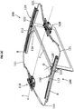
- the Figures 2A to 2E show an embodiment of a roof system for the vehicle roof 2 in a respective perspective view Figure 1 in different positions of a display arrangement 7, which can be set reliably and comfortably by means of a device 100.
- the roof system also has guide rails 8 which are laterally attached with respect to a longitudinal axis L and which couple the device 100 to the vehicle roof 2 and which are designed to guide components of the device 100.
- a first drive unit 118 and a second drive unit 128 are connected to a first drive cable 111 and a second drive cable 121.
- the first and the second drive units 118 and 128 preferably each comprise an electric motor, by means of which the respective first drive cable 111 and second drive cable 121 can be driven.
- the first drive unit 118 is arranged in or on a front region of the roof system and is designed to drive a first lever mechanism 110 of the device 100.
- the second drive unit 128 is arranged in or on a rear region of the roof system and is designed to drive a second lever mechanism 120 of the device 100.
- top, bottom, front, “rear”, “left”, “right” as well as “vertical” and “horizontal” denote directions, orientations or positions which relate to one another operational use of the device 100 in an operational motor vehicle 1 according to the Figure 1 Respectively.
- the drawn-in longitudinal axis L also has an arrow symbol which indicates a common direction of travel for better orientation.
- the described display arrangement 7 is provided in particular for vehicle occupants on the rear seat, which can be lowered and aligned easily and comfortably by means of the described device 100 if required.
- the longitudinal axis L can be regarded as the longitudinal axis of the roof system, the vehicle roof 2, the motor vehicle 1 and / or the device 100.
- the roof system has two devices 100, which are arranged on opposite sides and are coupled to a respective guide rail 8.
- the further device 100 has a correspondingly analog structure, which is to be understood as mirror-symmetrical with respect to the central longitudinal axis L with regard to the arrangement and design of the respective components.
- the device 100 has the first and the second lever mechanisms 110, 120, which are coupled to the display arrangement 7.
- the first lever mechanism 110 is designed for pivoting and pivoting and moving the display arrangement 7.
- the second lever mechanism 120 is designed to set a predetermined alignment angle A of the display arrangement 7.
- the first lever mechanism 110 has the first drive cable 111, a first guide slider 112 and a display lever arrangement 114, 115, 116, which can be moved electrically by means of the first drive unit 118.
- the second lever mechanism 120 has the second drive cable 121, a second guide slider 122 and a coupling lever 127, which can be moved electrically by means of the second drive unit 128.
- the first and the second guide sliders 112, 122 are coupled to one another by means of the coupling lever 127, so that regardless of a position of the display arrangement 7, which is set by means of the first lever mechanism 110, a distance D between the first and the second guide sliders 112, 122 and thereby an alignment angle A of the display arrangement 7 can be predetermined by means of the second lever mechanism 120.
- Figure 2A shows the display arrangement 7 in a folded state in a view from the rear left with respect to the ready-to-use motor vehicle 1 according to FIG Figure 1 .
- Figure 2B shows the display arrangement 7 in a rear unfolded position.
- Figure 2C shows the display arrangement 7 in the rear extended position according to Figure 2B , which is also angle-adjusted.
- an orientation angle of 15 ° can be set in relation to a vertical axis, in order to make viewing the display arrangement 7 particularly pleasant.
- This angle setting is achieved by the controlled formation of a predetermined distance D between the guide sliders 112 and 122.
- the guide sliders 112, 122 In a folded state according to Figure 2A , the guide sliders 112, 122 have a distance D0, which is reduced to a first distance D1 when unfolded (cf. Figures 7A-7C ).
- the distance D1 is zero, for example, so that the guide sliders 112, 122 make contact.
- the distance D1 can also be designed to be greater than zero and allow the display arrangement 7 to be inclined forwards and backwards in both directions.
- the guide sliders 112, 122 In order to set up a desired display inclination, the guide sliders 112, 122 are again separated from one another in a controlled manner and the distance D1 is specifically increased to a distance D2.
- Figure 2D shows the display arrangement 7 in an extended position moved forward. This can be done based on the extended position Figure 2B take place by driving the guide sliders 112, 122 forward by means of the first lever mechanism 110. Alternatively, this can also be based on the aligned state Figure 2C take place by the angle-adjusted display arrangement 7 to the front is moved and subsequently the set alignment angle A is withdrawn again or is set to essentially 0 °.
- Figure 2E shows the display arrangement 7 in a forwardly moved, front position, in which an orientation angle of, for example, 10 °, 15 ° or 20 ° to the vertical is set.
- the angle adjustment is possible continuously, so that a desired alignment angle A can be set up to a maximum predetermined angle value.
- Figures 3A to 3E show the display arrangement 7 in different positions in a respective side view from the left outside.
- Figure 3A shows the display arrangement 7 in a folded state.
- Figure 3B shows the display arrangement 7 in an unfolded state in a rear position.
- Figure 3C shows the display arrangement 7 in a rear, angle-adjusted position, in which the alignment angle A has, for example, a value of 15 ° to the vertical.
- Figure 3D shows the display arrangement 7 in the front position.
- Figure 3E shows the display arrangement 7 in a forwardly displaced, angle-adjusted position, in which the alignment angle A has, for example, a value of 15 ° to the vertical.
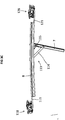
- Figure 4A shows the display arrangement 7 in a rear, unfolded position with a view of FIG Angle adjustment mechanism according to a view from the top left rear. For better clarity, the guide rail 8 is hidden.
- Figure 4B shows the display arrangement 7 in a rear, unfolded position with a view of the angle adjustment mechanism according to a view from the bottom left behind.
- the guide sliders 112 and 122 each have two sliding feet 119 and 129 with which they can slide in a guided manner within a sliding channel of the guide rail 8.
- the display arrangement 7 is unfolded by means of the first lever mechanism 110, which includes, among other things, the display lever arrangement in the form of a first lever arrangement 113 with a main link 114, a first rocking or pivoting lever 115 and a second rocking or pivoting lever 116.
- the display lever arrangement 114, 115, 116 is pivotally coupled to the first guide slider 112.
- the main link 114 is on the one hand pivotally coupled to the first guide slider 112 and on the other hand pivotally coupled to the display arrangement 7.
- the first pivot lever 115 is pivotally coupled to the display arrangement 7 on the one hand and pivotably to the second guide slider 122 on the other hand.
- the second pivot lever 116 is coupled on the one hand pivotably to the second guide slider 122 and on the other hand pivotably to the display arrangement 7.
- the first drive cable 111 is coupled to the second guide conductor 122, so that by actuating the first drive cable 111 the second guide slider 122 is moved towards the first guide slider 112 and the distance D between the two guide sliders 112 and 122 is reduced (cf. Figures 4A to 5E ). From a given distance between the guide sliders 112 and 122, for example at a position in which the display arrangement 7 is folded out vertically, the second guide slider 122 couples with the first guide slider 112 and drives it forward in order to move the folded out display arrangement 7 in the direction of the longitudinal axis L.
- the second lever arrangement 123 comprises a first swivel lever 124, a second swivel lever 125 and a guide lever 126 with respective links 124k, 125k and 126k, which prescribe horizontal guidance in the xy plane (see. Figure 1 ).
- the swivel levers 124, 125 can each also be referred to as adjustment sliders 124, 125, which, driven by the second drive unit 128, execute a sliding movement in the guide rail 8 for adjusting the display arrangement 7.
- the guide lever 126 of the second lever arrangement 123 can also be referred to as a guide element 126 which, when actuated in cooperation with the coupling lever 127 and the first guide slider 112, executes a leading movement for aligning the display arrangement 7.
- the first adjustment slider 124 is coupled on the one hand to the second drive cable 121 and on the other hand to the second adjustment slider 125, which has coupling elements, for example in the form of cylindrical pins, which engage in the link 124k of the first adjustment slider 124.
- the second adjustment slide 125 is coupled on the one hand to the first adjustment slide 124 and on the other hand to the guide element 126.
- the coupling between the guide element 126 and the second adjustment slider 125 takes place by means of the coupling lever 127, which also couples the two guide sliders 112 and 122 to one another.
- the coupling lever 127 has coupling elements on both sides, that is to say on an upper side and a lower side, for example in the form of cylindrical pins, which engage vertically on the one hand in the link 125k of the second adjusting slide 125 and on the other hand in the link 126k of the guide element 126.
- the coupling lever 127 has a further coupling element which engages in a coupling opening provided for this purpose on the first guide slider 112 and forms the mechanical coupling between the two guide sliders 112 and 122.
- the guide element 126 is preferably formed in one piece with the second guide glider 122 and, for example, integrated into a horizontally extending plate-shaped element of the second guide glider 122 (see FIG. Figures 4A and 6A ).
- the guide element 126 can also form an element of the second lever arrangement 123 that is separate from the second guide slider 122 and can be firmly connected to the second guide slider 122.
- the scenes 124k, 125k and 126k each form guide tracks that are closed on both sides with respect to a horizontal plane, the opposite ends of which can also be closed and form a stop or end position of the respective scenery track (cf. Figures 5B and 5D ).
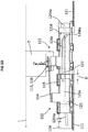
- Figure 5A shows the display arrangement 7 in a rear, unfolded position with a view of the angle adjustment mechanism according to a view from the left. For better clarity, the guide rail 8 is hidden.
- Figure 5B shows the display arrangement 7 in a rear, unfolded position with a view of the angle adjustment mechanism in a top view or a view from above.
- the scenes 124k, 125k and 126k of the respective adjustment sliders 124, 125 and the guide element 126 can be seen from this illustration.
- the link 124k is designed in two parts and has a sloping link section 124ka in a front and a rear area, into which a respective coupling pin of the second adjustment slider 125 arranged above engages.
- the length and oblique orientation of the link portions 124ka determine a horizontal offset Vh with respect to the in Figure 1 drawn y-direction, which is converted by means of the second lever arrangement 123 and the coupling between the guide sliders 112 and 122 into a change in the distance between the guide sliders 112 and 122 and an angular adjustment of the display arrangement 7.
- Such setting up of the alignment angle A and the angular range possible for adjustment are further influenced by an inclined link section 126ka, which includes a predetermined length LKA and a predetermined angle to the longitudinal axis L. In this way, the possible angular range and an adjustment speed of the display arrangement can also be determined.
- Figure 5C shows the display arrangement 7 in a rear, unfolded position with a view of the angle adjustment mechanism according to a view from the left.
- Figure 5D shows the display arrangement 7 in a rear, unfolded position with a view of the angle adjustment mechanism in a top view or a view from above.
- Figure 5E shows the display arrangement 7 in a folded-in position, which for example represents a parking position, from the center of a vehicle with a view to the left outside.
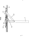
- Figure 6A shows the display arrangement 7 in a rear, unfolded and angle-adjusted position with a view of the angle adjustment mechanism according to a view from the rear left.
- Figure 6B shows the display arrangement 7 in a rear, unfolded and angle-adjusted position with a view of the angle adjustment mechanism according to a view from the bottom left behind.
- Figure 6C shows the display arrangement 7 in a rear, unfolded position with a view of the adjustment mechanism according to a view from a vehicle center with a view to the left outside.
- Figure 6D shows the display arrangement 7 in a rear, unfolded and angle-adjusted position with a view of the adjustment mechanism according to a view from a vehicle center with a view to the left outside.
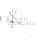
- Figure 7A shows the lever mechanism of the device 100 in a schematic representation, in which the display arrangement is folded.
- the view corresponds to a view from the center of the vehicle with a view to the left outside, again with reference to a normal direction of travel of the motor vehicle 1.
- a four-bar linkage is used, which is formed by the first lever arrangement 113, so that the driving main link 114 has a sufficient lever arm H to reliably expand and retract the display arrangement 7.
- the lever arm H shown executes a movement with respect to a virtual pivot point Dv and therefore enables a particularly flat and space-saving structure of the device 100.
- the virtual pivot point forms a momentary pole of the four-bar linkage.
- a simple pivot point is also conceivable, but at which an installation space which is restricted at the top must be taken into account.
- Figure 7B shows the lever mechanism of the device 100 Figure 7A in an unfolded state.
- the distance D0 between the guide sliders 112 and 122 of the folded-in display arrangement 7 is reduced to the first distance D1.
- Figure 7C shows the lever mechanism of the device 100 according to FIGS Figures 7A and 7B in an unfolded and angle-adjusted state in a symbolic representation.
- the first distance D1 between the two guide sliders 112 and 122 is set to second distance D2 increased.
- the distance D1 can be increased to a value D2 during the entire travel of the display arrangement 7 along the longitudinal axis L or the guide rails 8.
- the device 100 has interacting lever and guide elements which enable a space-saving mechanism for comfortable and reliable adjustment of the display arrangement 7.
- the two guide sliders 112, 122 enable both the folding and folding and the movement as well as the angular adjustment of the display arrangement 7.
- the angular adjustment motor or the second drive unit 128 is preferably permanently installed, so that no moving cables need to be laid on the screen, as is the case for example with a servomotor on the back of the display.
- the adjustment mechanism described is arranged essentially horizontally, in the direction of which, in contrast to the vertical direction, more installation space is available.
Abstract
Eine Vorrichtung (100) zum Einstellen einer Displayanordnung (7) für ein Fahrzeugdach (2) umfasst eine erste und eine zweite Hebelmechanik (110, 120), die mit der Displayanordnung (7) koppelbar sind, wobei die erste Hebelmechanik (110) zum Auf- und Einschwenken und Verfahren der Displayanordnung (7) und die zweite Hebelmechanik (120) zum Einstellen eines vorgegebenen Ausrichtungswinkels (A) der Displayanordnung (7) ausgebildet sind. Die erste Hebelmechanik (110) weist ein erstes Antriebskabel (111), einen ersten Führungsgleiter (112) und eine Displayhebelanordnung (114, 115, 116) auf, die mittels einer ersten Antriebseinheit (118) elektrisch verfahrbar sind. Die zweite Hebelmechanik (120) weist ein zweites Antriebskabel (121) und einen zweiten Führungsgleiter (122) auf, die mittels einer zweiten Antriebseinheit (128) elektrisch verfahrbar sind. Der erste und der zweite Führungsgleiter (112, 122) sind hinsichtlich eines gemeinsamen Bezugspunkts zumindest abschnittsweise mit unterschiedlichen Bewegungsgeschwindigkeiten verfahrbar , sodass unabhängig von einer Position der Displayanordnung (7), die mittels der ersten Hebelmechanik (110) eingestellt ist, ein Abstand (D) zwischen dem ersten und dem zweiten Führungsgleiter (112, 122) und dadurch ein Ausrichtungswinkel (A) der Displayanordnung (7) mittels der zweiten Hebelmechanik (120) vorgegeben einstellbar sind.A device (100) for setting a display arrangement (7) for a vehicle roof (2) comprises a first and a second lever mechanism (110, 120) which can be coupled to the display arrangement (7), the first lever mechanism (110) for opening - Swinging in and moving the display arrangement (7) and the second lever mechanism (120) for setting a predetermined orientation angle (A) of the display arrangement (7) are formed. The first lever mechanism (110) has a first drive cable (111), a first guide slider (112) and a display lever arrangement (114, 115, 116) which can be moved electrically by means of a first drive unit (118). The second lever mechanism (120) has a second drive cable (121) and a second guide slider (122), which can be moved electrically by means of a second drive unit (128). The first and second guide sliders (112, 122) can be moved at least in sections with different movement speeds with respect to a common reference point, so that a distance (D) is independent of a position of the display arrangement (7) which is set by means of the first lever mechanism (110). between the first and the second guide slider (112, 122) and thereby an orientation angle (A) of the display arrangement (7) can be predetermined by means of the second lever mechanism (120).
Description
Die Erfindung betrifft eine Vorrichtung und ein Verfahren zum Einstellen einer Displayanordnung für ein Fahrzeugdach. Die Erfindung betrifft weiter ein Fahrzeugdach für ein Kraftfahrzeug mit einer solchen Vorrichtung.The invention relates to a device and a method for adjusting a display arrangement for a vehicle roof. The invention further relates to a vehicle roof for a motor vehicle with such a device.
Einige Kraftfahrzeuge weisen eine Displayanordnung auf, die auf Wunsch ein Unterhaltungsprogramm bereitstellen kann und zu einem erhöhten Komfort des Kraftfahrzeugs beiträgt. Gegebenenfalls ist eine solche Displayanordnung mit einem Kinematikkonzept versehen, welches bei Bedarf ein Ein- und Ausklappen der Displayanordnung ermöglicht. Dabei ist es eine Herausforderung eine platzsparende und kostengünstige Anordnung einer solchen Unterhaltungselektronik zu ermöglichen.Some motor vehicles have a display arrangement which, if desired, can provide an entertainment program and contribute to increased comfort of the motor vehicle. If necessary, such a display arrangement is provided with a kinematic concept which, if necessary, enables the display arrangement to be folded in and out. It is a challenge to enable a space-saving and inexpensive arrangement of such consumer electronics.
Der Erfindung liegt die Aufgabe zugrunde, eine Vorrichtung und ein Verfahren zum Einstellen einer Displayanordnung für ein Fahrzeugdach zu schaffen, die jeweils ein zuverlässiges und sicheres Ausbilden einer gewünschten Einstellung der Displayanordnung ermöglichen und zudem zu einem kostengünstigen und komfortablen Kraftfahrzeug beitragen können.The invention has for its object to provide a device and a method for adjusting a display arrangement for a vehicle roof, each of which enables reliable and safe formation of a desired setting of the display arrangement and can also contribute to an inexpensive and comfortable motor vehicle.
Die Aufgabe wird durch die Merkmale der unabhängigen Patentansprüche gelöst. Vorteilhafte Ausgestaltungen sind in den Unteransprüchen angegeben.The object is solved by the features of the independent claims. Advantageous refinements are specified in the subclaims.
Eine erfindungsgemäße Vorrichtung zum Einstellen einer Displayanordnung für ein Fahrzeugdach umfasst eine erste Hebelmechanik und eine zweite Hebelmechanik, die mit der Displayanordnung koppelbar sind, wobei die erste Hebelmechanik zum Auf- und Einschwenken und Verfahren der Displayanordnung und die zweite Hebelmechanik zum Einstellen eines vorgegebenen Ausrichtungswinkels der Displayanordnung ausgebildet sind. Die erste Hebelmechanik weist ein erstes Antriebskabel, einen ersten Führungsgleiter und eine Displayhebelanordnung auf, die mittels einer ersten Antriebseinheit elektrisch verfahrbar sind. Dabei können der erste Führungsgleiter und die Displayhebelanordnung direkt bzw. unmittelbar oder indirekt bzw. mittelbar mittels des ersten Antriebskabels angetrieben werden. Die zweite Hebelmechanik weist ein zweites Antriebskabel und einen zweiten Führungsgleiter auf, die mittels einer zweiten Antriebseinheit elektrisch verfahrbar sind. Dabei kann der zweite Führungsgleiter direkt bzw. unmittelbar oder indirekt bzw. mittelbar mittels des zweiten Antriebskabels angetrieben werden. Der erste und der zweite Führungsgleiter sind hinsichtlich eines gemeinsamen Bezugspunkts zumindest abschnittsweise mit unterschiedlichen Bewegungsgeschwindigkeiten verfahrbar, sodass unabhängig von einer Position der Displayanordnung, die mittels der ersten Hebelmechanik eingestellt ist, ein Abstand zwischen dem ersten und dem zweiten Führungsgleiter und dadurch ein Ausrichtungswinkel der Displayanordnung mittels der zweiten Hebelmechanik vorgegeben einstellbar sind.A device according to the invention for adjusting a display arrangement for a vehicle roof comprises a first lever mechanism and a second lever mechanism, which can be coupled to the display arrangement, the first lever mechanism for pivoting up and in and pivoting and moving the display arrangement and the second lever mechanism for setting a predetermined alignment angle of the display arrangement are trained. The first lever mechanism has a first drive cable, a first guide slider and a display lever arrangement which can be moved electrically by means of a first drive unit. The first guide slider and the display lever arrangement can be driven directly or directly or indirectly or indirectly by means of the first drive cable. The second lever mechanism has a second drive cable and a second guide slider, which can be moved electrically by means of a second drive unit. The second guide slider can be driven directly or directly or indirectly or indirectly by means of the second drive cable. The first and second guide sliders can be moved at least in sections with different movement speeds with respect to a common reference point, so that regardless of a position of the display arrangement that is set by means of the first lever mechanism, a distance between the first and the second guide sliders and thereby an orientation angle of the display arrangement by means of the second lever mechanism can be preset.
Mittels der beschriebenen Vorrichtung ist ein komfortables und zuverlässiges Einstellen einer gewünschten Position und Ausrichtung einer Displayanordnung möglich, welche zudem kostengünstig realisierbar und platzsparend in den Aufbau eines Fahrzeugdachs für ein Kraftfahrzeug integrierbar ist.By means of the described device, a comfortable and reliable setting of a desired position and orientation of a display arrangement is possible, which also is inexpensive to implement and can be integrated into the structure of a vehicle roof for a motor vehicle in a space-saving manner.
Die Vorrichtung realisiert eine elektrisch betätigbare Mechanik zum Schwenken und Verfahren einer Displayanordnung, welche ein bequemes Absenken, Ausrichten und Einstellen eines Displays in einem Fahrzeuginnenraum ermöglicht. Mittels der ersten Hebelmechanik und einer mit dieser koppelbaren ersten Antriebseinheit kann die Displayanordnung kontrolliert und zuverlässig ein- und ausgeschwenkt und verfahren werden, um eine gewünschte Schwenk- oder Hub-Position der Displayanordnung auszubilden. Mittels der zweiten Hebelmechanik und einer mit dieser koppelbaren zweiten Antriebseinheit kann unabhängig von der Schwenk- oder Hub-Position der Displayanordnung, die mittels der ersten Hebelmechanik eingestellt wurde, eine Winkelausrichtung verändert und im Sinne einer Feineinstellung manipuliert oder nachjustiert werden.The device realizes an electrically actuable mechanism for pivoting and moving a display arrangement, which enables a comfortable lowering, alignment and adjustment of a display in a vehicle interior. By means of the first lever mechanism and a first drive unit that can be coupled to this, the display arrangement can be swiveled in and out and moved in a controlled and reliable manner in order to form a desired swivel or lifting position of the display arrangement. By means of the second lever mechanism and a second drive unit that can be coupled to this, an angular orientation can be changed and manipulated or readjusted in the sense of a fine adjustment, regardless of the pivoting or lifting position of the display arrangement that was set by means of the first lever mechanism.
Die beschriebene Vorrichtung mit der ersten und zweiten Hebelmechanik kann insbesondere kostengünstig und platzsparend realisiert werden, sodass ein Bauraumbedarf in einem Fahrzeuginnenraum gering gehalten werden kann. Die Vorrichtung kann insbesondere in einem Fahrzeugdach integriert sein oder an einem solchen angeordnet sein und dennoch eine komfortable Kopfbewegungsfreiheit in dem Fahrzeuginnenraum ermöglichen. Auf diese Weise kann zu einer hochwertigen Unterhaltungsmöglichkeit in einem Kraftfahrzeug beigetragen werden.The described device with the first and second lever mechanisms can be implemented in a particularly cost-effective and space-saving manner, so that a space requirement in a vehicle interior can be kept low. The device can, in particular, be integrated in a vehicle roof or be arranged on such a roof and still allow comfortable head movement in the vehicle interior. In this way, a high-quality entertainment possibility in a motor vehicle can be contributed.
Gemäß einer Weiterbildung weist die zweite Hebelmechanik ferner einen Kopplungshebel auf, der den ersten und zweiten Führungsgleiter miteinander koppelt.According to a development, the second lever mechanism also has a coupling lever which couples the first and second guide sliders to one another.
Gemäß einer Weiterbildung der Vorrichtung weist die zweite Hebelmechanik eine zweite Hebelanordnung auf, die mit dem zweiten Antriebskabel und mittels des Kopplungshebels mit dem zweiten Führungsgleiter gekoppelt ist und die dazu eingerichtet ist, einen horizontalen Versatz in einer horizontalen Ebene, die senkrecht zu einer Haupterstreckungsebene der ausgeklappten Displayanordnung ist, in eine Änderung des Abstandes zwischen den Führungsgleitern zu überführen.According to a development of the device, the second lever mechanism has a second lever arrangement which is coupled to the second drive cable and by means of the coupling lever to the second guide slider and which is set up to have a horizontal offset in a horizontal plane which is perpendicular to a main extension plane of the extended one Display arrangement is to convert into a change in the distance between the guide sliders.
Gemäß einer bevorzugten Weiterbildung der Vorrichtung weist die zweite Hebelanordnung einen ersten und einen zweiten Schwenkhebel und einen Führungshebel mit jeweiligen Kulissen auf, die mit dem zweiten Antriebskabel und mit dem Kopplungshebel gekoppelt sind und die mittels der durch die jeweiligen Kulissen vorgegebenen Führung dazu ausgebildet sind, einen vorgegebenen Abstand zwischen den Führungsgleitern einzustellen. Die Schwenkhebel der zweiten Hebelanordnung können auch als Verstellgleiter bezeichnet werden, die angetrieben von einer zweiten Antriebseinheit eine in der Führungsschiene gleitende Bewegung zum Verstellen der Displayanordnung ausführen. Der Führungshebel der zweiten Hebelanordnung kann auch als Führungselement bezeichnet werden, das bei Betätigung im Zusammenwirken mit dem Kopplungshebel und dem ersten Führungsgleiter eine führende Bewegung zum Ausrichten der Displayanordnung ausführt.According to a preferred development of the device, the second lever arrangement has a first and a second pivot lever and a guide lever with respective links, which are coupled to the second drive cable and to the coupling lever and which are designed for this purpose by means of the guide specified by the respective links set the predetermined distance between the guide sliders. The pivot levers of the second lever arrangement can also be referred to as adjustment sliders which, driven by a second drive unit, execute a sliding movement in the guide rail for adjusting the display arrangement. The guide lever of the second lever arrangement can also be referred to as a guide element which, when actuated in cooperation with the coupling lever and the first guide slider, performs a leading movement for aligning the display arrangement.
Mittels solcher Weiterbildungen kann auf einfache und kostengünstige Weise eine lineare Bewegung des zweiten Antriebskabels und des damit gekoppelten Führungsgleiters entlang der Längsachse in eine Winkelbewegung der Displayanordnung umgewandelt werden, welche einen vorgebbaren Einstellungsbereich eines Ausrichtungswinkels ermöglicht. Der horizontale Versatz und die damit ermöglichte Einstellung des Ausrichtungswinkels geben einen möglichen Winkelbereich vor und tragen zu einem besonders platzsparenden und flachen Aufbau der Vorrichtung bei. Vorzugsweise wird mittels der Vorrichtung ein horizontaler Versatz bereitgestellt, welcher eine Winkelverstellung des Ausrichtungswinkels der vertikal ausgeklappten Displayanordnung von bis zu 15° ermöglicht. Darüber hinaus sind auch andere Winkelbereiche möglich.By means of such further developments, a linear movement of the second drive cable and the guide slider coupled to it along the longitudinal axis can be converted in a simple and inexpensive manner into an angular movement of the display arrangement, which movement can be predetermined Setting range of an alignment angle allows. The horizontal offset and the adjustment of the alignment angle made possible thereby specify a possible angular range and contribute to a particularly space-saving and flat construction of the device. A horizontal offset is preferably provided by means of the device, which enables an angle adjustment of the orientation angle of the vertically unfolded display arrangement of up to 15 °. Other angular ranges are also possible.
Im Rahmen dieser Beschreibung bezeichnen Begriffe, wie "oben", "unten", "vorne", "hinten", "links", "rechts" sowie "vertikal" und "horizontal", Richtungsangaben oder Ausrichtungen, welche sich auf einen betriebsgemäßen Einsatz in einem betriebsbereiten Kraftfahrzeug beziehen. Die beschriebene Displayanordnung, welche mittels der beschriebenen Vorrichtung bei Bedarf einfach und komfortabel abgesenkt und ausgerichtet werden kann, ist insbesondere für Fahrzeuginsassen auf der hinteren Sitzbank vorgesehen. Eine horizontale Bewegungskomponente bezieht sich somit auf eine Ebene, die im Wesentlichen parallel zu dem Fahrzeugdach ist. Eine vertikale Ausrichtung erfolgt somit in einer Ebene, die im Wesentlichen senkrecht zu der horizontalen Ebene oder dem Fahrzeugdach ist.Within the scope of this description, terms such as "top", "bottom", "front", "rear", "left", "right" as well as "vertical" and "horizontal" denote directions or orientations which relate to operational use in an operational motor vehicle. The described display arrangement, which can be easily and conveniently lowered and aligned by means of the described device, is particularly intended for vehicle occupants on the rear seat. A horizontal movement component thus refers to a plane that is essentially parallel to the vehicle roof. A vertical alignment thus takes place in a plane that is essentially perpendicular to the horizontal plane or the vehicle roof.
In einem eingeklappten Zustand befindet sich die Displayanordnung beziehungsweise das Display hinsichtlich seiner Haupterstreckungsebene vorzugsweise parallel zu dem Fahrzeugdach, sodass ein Ausklappen oder Aufschwenken in Richtung des Fahrzeuginnenraums erfolgt, indem die Displayanordnung mittels der ersten Hebelmechanik um eine oder mehrere Schwenkachsen umgeklappt wird und in einem ausgeklappten Zustand beispielsweise vertikal in den Fahrzeuginnenraum ausgerichtet ist. Mittels der zweiten Hebelmechanik kann nun eine zuverlässige und komfortable Feineinstellung der Winkelausrichtung der Displayanordnung erfolgen, indem mittels Antreiben des zweiten Antriebskabels ein Abstand zwischen den Führungsgleitern gezielt verändert wird, welche das kontrollierte Ausbilden einer gewünschten Neigung der vertikal ausgerichteten Displayanordnung bewirkt. Auf diese Weise ist ein gewünschter Ausrichtungswinkel des Displays einstellbar und es kann zu einem besonders angenehmen und komfortablen Unterhaltungsprogramm beigetragen werden.In a folded-in state, the display arrangement or the display is preferably parallel to the vehicle roof with regard to its main extension plane, so that the display arrangement is folded out or swung open in the direction of the vehicle interior by the first lever mechanism being folded over one or more pivot axes and in a folded-out state for example vertically in the Vehicle interior is aligned. By means of the second lever mechanism, a reliable and comfortable fine adjustment of the angular orientation of the display arrangement can now be carried out by specifically changing a distance between the guide slides by driving the second drive cable, which causes the controlled formation of a desired inclination of the vertically oriented display arrangement. In this way, a desired orientation angle of the display can be set and it can contribute to a particularly pleasant and comfortable entertainment program.
Gemäß einer weiteren bevorzugten Weiterbildung der Vorrichtung weist der erste Schwenkhebel und der Führungshebel in den zugehörigen Kulissen einen jeweils länglichen Kulissenabschnitt auf, der relativ zu der Längsachse schräg verläuft und eine vorgegebene Länge besitzt und in einer horizontalen Ebene einen vorgegebenen Winkel zu der Längsachse einschließt.According to a further preferred development of the device, the first pivot lever and the guide lever each have an elongated link section in the associated links, which is oblique relative to the longitudinal axis and has a predetermined length and includes a predetermined angle to the longitudinal axis in a horizontal plane.
Gemäß einer weiteren Weiterbildung der Vorrichtung sind die vorgegebene Länge und der vorgegebene Winkel der länglichen Kulissenabschnitte relativ zu der Längsachse in Abhängigkeit von einer Einstellgeschwindigkeit zum Einstellen eines vorgegebenen Ausrichtungswinkels der Displayanordnung ausgebildet. Die Länge und die geneigte Ausrichtung der länglichen Kulissenabschnitte bestimmen im Zusammenwirken mit der zweiten Antriebseinheit die Einstellgeschwindigkeit und den möglichen einstellbaren Winkelbereich für den Ausrichtungswinkel der Displayanordnung. Auf diese Weise kann eine Möglichkeit zur zügigen Ausrichtung oder zur langsamen, sanften Ausrichtung der Displayanordnung eingerichtet werden.According to a further development of the device, the predetermined length and the predetermined angle of the elongated link sections relative to the longitudinal axis are designed as a function of an adjustment speed for adjusting a predetermined orientation angle of the display arrangement. In cooperation with the second drive unit, the length and the inclined alignment of the elongated link sections determine the adjustment speed and the possible adjustable angle range for the alignment angle of the display arrangement. In this way, a possibility for rapid alignment or for slow, gentle alignment of the display arrangement can be set up.
Gemäß einer weiteren bevorzugten Weiterbildung der Vorrichtung ist das erste Antriebskabel mit dem zweiten Führungsgleiter gekoppelt, sodass der erste Führungsgleiter mittels des zweiten Führungsgleiters antreibbar ist. Auf diese Weise kann der zweite Führungsgleiter mittels der ersten Antriebseinheit direkt aktiv und der erste Führungsgleiter indirekt passiv angetrieben werden. Der zweite Führungsgleiter koppelt zum Beispiel an einer vorgegebenen Position relativ zu der führenden Führungsschiene mit dem ersten Führungsgleiter und treibt diesen entlang der Führungsschiene vor sich her. Dabei können die Führungsgleiter direkt miteinander koppeln und sich kontaktieren und einen Abstand von etwa Null zueinander aufweisen, oder mit einem vorgegebenen Gleiterabstand größer Null miteinander gekoppelt werden. Ein Einstellen des Ausrichtungswinkels durch Verändern des Abstands zwischen den Führungsgleitern erfolgt dann mittels der zweiten Antriebseinheit.According to a further preferred development of the device, the first drive cable is coupled to the second guide slider, so that the first guide slider can be driven by means of the second guide slider. In this way, the second guide slider can be driven directly by the first drive unit and the first guide slider can be driven indirectly passively. For example, the second guide slider couples to the first guide slider at a predetermined position relative to the leading guide rail and drives it along the guide rail in front of it. In this case, the guide sliders can couple directly to one another and make contact and have a distance of approximately zero from one another, or can be coupled to one another with a predetermined slider distance greater than zero. The alignment angle is then adjusted by changing the distance between the guide sliders by means of the second drive unit.
Alternativ kann die erste Antriebseinheit aber auch mit dem ersten oder zweiten Führungsgleiter und die zweite Antriebseinheit mit dem jeweils anderen der beiden Führungsgleiter gekoppelt sein, um ein Ausklappen der Displayanordnung und Einstellen des Ausrichtungswinkels durch Abstandsveränderung zwischen den Führungsgleitern zu ermöglichen.Alternatively, the first drive unit can also be coupled to the first or second guide slider and the second drive unit can be coupled to the other of the two guide sliders in order to enable the display arrangement to be unfolded and the alignment angle to be set by changing the distance between the guide sliders.
Gemäß einer weiteren bevorzugten Weiterbildung umfasst die Vorrichtung die erste und die zweite Antriebseinheit von denen eine oder beide einen Elektromotor aufweisen, der zum Auf- und Einschwenken und zum Verfahren der Displayanordnung und/oder der zum Einstellen eines Abstands zwischen den Führungsgleitern und zum Einstellen eines Ausrichtungswinkels der Displayanordnung mit dem jeweiligen Antriebskabel gekoppelt ist.According to a further preferred development, the device comprises the first and the second drive unit, one or both of which have an electric motor, which is used for pivoting on and in and for moving the display arrangement and / or for setting a distance between the guide slides and for setting an alignment angle the display arrangement is coupled to the respective drive cable.
Die erste und/oder die zweite Antriebseinheit sind so ausgebildet, dass der erste und der zweite Führungsgleiter hinsichtlich eines gemeinsamen Bezugspunkts, zum Beispiel relativ zu einer Führungsschiene, mit der die Führungsgleiter gekoppelt werden, zumindest abschnittsweise mit unterschiedlichen Bewegungsgeschwindigkeiten verfahrbar sind. Die unterschiedlichen Geschwindigkeiten des ersten und des zweiten Führungsgleiters können insbesondere mittels einer elektronischen Drehzahlregelung der ersten und/oder der zweiten Antriebseinheit eingestellt werden. Somit kann ein besonders übersichtlicher und platzsparender Aufbau der Vorrichtung realisiert werden. Die Führungsgleiter sind jeweils mit der Displayanordnung gekoppelt und ermöglichen aufgrund unterschiedlicher Antriebsgeschwindigkeiten ein Aufklappen und Verschwenken der Displayanordnung.The first and / or the second drive unit are designed such that the first and the second guide slider can be moved at least in sections with different movement speeds with respect to a common reference point, for example relative to a guide rail with which the guide slider is coupled. The different speeds of the first and second guide sliders can be set in particular by means of electronic speed control of the first and / or the second drive unit. A particularly clear and space-saving construction of the device can thus be realized. The guide sliders are each coupled to the display arrangement and, due to different drive speeds, enable the display arrangement to be opened and pivoted.
Mittels der Vorrichtung ist eine Mechanik mit elektrisch verstellbarer Displayausrichtung ausbildbar, die im Vergleich zu konventionellen Konzepten, die zum Beispiel ein Verschwenken eines Displays mit einem auf der Rückseite des Displays angebrachten Verstellmotors ermöglichen, einige Vorteile bietet. Insbesondere ein Platzbedarf in einer vertikalen Richtung kann gering gehalten werden, sodass eine Parkposition der Displayanordnung nicht so nahe an den Kopfkreisen von Fahrzeuginsassen liegt und eine Sicht nach vorne nicht oder weniger eingeschränkt wird. Die erste und die zweite Hebelmechanik können insbesondere mittels einfacher im Fahrzeugdach fest verbauter Elektroantriebe betätigt werden, sodass zum Beispiel zum Einstellen und Ausrichten der Displayanordnung keine Linearantriebe erforderlich sind und ein besonders platzsparender Aufbau realisiert werden kann.The device can be used to form a mechanism with an electrically adjustable display orientation, which offers a number of advantages compared to conventional concepts which, for example, allow a display to be pivoted with an adjustment motor mounted on the rear of the display. In particular, a space requirement in a vertical direction can be kept small, so that a parking position of the display arrangement is not as close to the head circles of vehicle occupants and a view to the front is not restricted or is restricted less. The first and second lever mechanisms can be actuated in particular by means of simple electric drives permanently installed in the vehicle roof, so that, for example, no linear drives for setting and aligning the display arrangement are required and a particularly space-saving construction can be realized.
Das Abklappen oder Ausklappen der Displayanordnung erfolgt durch eine Verschiebung eines der beiden Führungsgleiter relativ zu dem anderen. Eine Verstellung des Verschwenkwinkels bzw. des Ausrichtungswinkels erfolgt durch eine Änderung des Abstands der beiden Führungsgleiter zueinander und kann über den gesamten Verfahrbereich der Displayanordnung durchgeführt werden.The display arrangement is folded or unfolded by displacing one of the two guide sliders relative to the other. The pivoting angle or the alignment angle is adjusted by changing the distance between the two guide sliders and can be carried out over the entire travel range of the display arrangement.
Ein erfindungsgemäßes Fahrzeugdach umfasst zwei Führungsschienen, die in Bezug auf eine Längsachse des Fahrzeugdachs auf gegenüberliegenden Seiten des Fahrzeugdachs angeordnet sind, und eine Ausgestaltung der zuvor beschriebenen Vorrichtung zum Einstellen einer Displayanordnung, die mittels der Führungsschienen mit dem Fahrzeugdach gekoppelt ist. Die Vorrichtung kann insbesondere bestehende Räume innerhalb einer jeweiligen Führungsschiene nutzen, die zum Beispiel auch zum Betreiben einer Verdunkelungsvorrichtung ausgebildet sind. Insbesondere können die erste und zweite Hebelmechanik innerhalb einer gemeinsamen Führungsschiene angeordnet sein, sodass sich die Hebelmechaniken eine gemeinsame Führungsschiene teilen.A vehicle roof according to the invention comprises two guide rails which are arranged on opposite sides of the vehicle roof with respect to a longitudinal axis of the vehicle roof, and an embodiment of the above-described device for adjusting a display arrangement which is coupled to the vehicle roof by means of the guide rails. The device can in particular use existing spaces within a respective guide rail, which are also designed, for example, to operate a blackout device. In particular, the first and second lever mechanisms can be arranged within a common guide rail, so that the lever mechanisms share a common guide rail.
In Bezug auf ein Fahrzeugdach kann die Vorrichtung insbesondere eine doppelte Anzahl der beschriebenen Komponenten umfassen, die hinsichtlich einer zentralen oder mittigen Längsachse des Fahrzeugdachs im Wesentlichen spiegelsymmetrisch ausgebildet und angeordnet sind. Das Fahrzeugdach mit der beschriebenen Vorrichtung trägt somit zu einem erhöhten Komfort eines Kraftfahrzeugs bei und ist im Vergleich zu konventionellen Kippeinrichtungen für ein Display kostengünstiger herstellbar. Dadurch, dass das Fahrzeugdach eine Ausgestaltung der zuvor beschriebenen Vorrichtung umfasst, sind, sofern zutreffend, sämtliche zuvor beschriebenen Merkmale und Eigenschaften der Vorrichtung auch für das Fahrzeugdach offenbart und umgekehrt.With regard to a vehicle roof, the device can in particular comprise a double number of the components described, which are designed and arranged essentially mirror-symmetrically with respect to a central or central longitudinal axis of the vehicle roof. The vehicle roof with the described device thus contributes to increased comfort of a motor vehicle and is compared to conventional tilting devices for one Display can be manufactured more cost-effectively. Due to the fact that the vehicle roof comprises an embodiment of the device described above, if applicable, all of the features and properties of the device described above are also disclosed for the vehicle roof and vice versa.
Ein erfindungsgemäßes Verfahren zum Einstellen einer Displayanordnung für ein Fahrzeugdach umfasst ein Betätigen einer ersten Hebelmechanik mittels Verfahren eines ersten Antriebskabels und eines an dem ersten Antriebskabel gekoppelten Führungsgleiters, der mittels einer schwenkbaren Displayhebelanordnung mit der Displayanordnung gekoppelt ist, und dadurch Schwenken der Displayanordnung und Ausbilden eines ausgeklappten Zustands der Displayanordnung. Das Verfahren umfasst weiter ein Betätigen einer zweiten Hebelmechanik mittels Verfahren eines zweiten Antriebskabels und Bewegen eines an dem zweiten Antriebskabel gekoppelten zweiten Führungsgleiters, der mittels eines Kopplungshebels mit einem ersten Führungsgleiter gekoppelt ist, und dadurch Einstellen eines vorgegebenen Abstands zwischen dem ersten und dem zweiten Führungsgleiter bezogen auf eine Längsachse des Fahrzeugdachs und dadurch Einstellen eines vorgegebenen Ausrichtungswinkels der Displayanordnung unabhängig von dem ausgebildeten ausgeklappten Zustand der Displayanordnung.A method according to the invention for adjusting a display arrangement for a vehicle roof comprises actuating a first lever mechanism by moving a first drive cable and a guide slider coupled to the first drive cable, which is coupled to the display arrangement by means of a pivotable display lever arrangement, and thereby pivoting the display arrangement and forming an extended one State of the display arrangement. The method further comprises actuating a second lever mechanism by moving a second drive cable and moving a second guide slider coupled to the second drive cable, which is coupled to a first guide slider by means of a coupling lever, and thereby adjusting a predetermined distance between the first and second guide sliders on a longitudinal axis of the vehicle roof and thereby setting a predetermined orientation angle of the display arrangement regardless of the unfolded state of the display arrangement.
Mittels des beschriebenen Verfahrens ist ein zuverlässiges und sicheres Ausbilden einer gewünschten Einstellung der Displayanordnung möglich und es kann zudem zu einem kostengünstigen und komfortablen Kraftfahrzeug beigetragen werden. Das Verfahren ist insbesondere mittels einer Ausgestaltung der zuvor beschriebenen Vorrichtung durchführbar, sodass, sofern zutreffend, sämtliche beschriebenen Merkmale und Eigenschaften der Vorrichtung auch für das Verfahren offenbart sind und umgekehrt.Using the described method, it is possible to reliably and securely form a desired setting of the display arrangement, and it can also contribute to an inexpensive and comfortable motor vehicle. The method can be carried out in particular by means of an embodiment of the device described above, so that, if applicable, all Features and properties of the device described are also disclosed for the method and vice versa.
Gemäß einer bevorzugten Weiterbildung des Verfahrens umfasst das Betätigen der ersten und der zweiten Hebelmechanik ein Ansteuern einer ersten Antriebseinheit, die mit dem ersten Antriebskabel gekoppelt ist, und dadurch Bewegen eines aus ersten oder zweiten Führungsgleiters, und ein Ansteuern einer zweiten Antriebseinheit, die mit dem zweiten Antriebskabel gekoppelt ist, und dadurch Bewegen des anderen aus ersten oder zweiten Führungsgleiters, sodass zumindest abschnittsweise unterschiedliche Bewegungsgeschwindigkeiten der beiden Führungsgleiter eingestellt sind. Das Einstellen der unterschiedlichen Bewegungsgeschwindigkeiten der beiden Führungsgleiter kann insbesondere ein Steuern einer Drehzahlregelung der ersten und/oder der zweiten Antriebseinheit umfassen.According to a preferred development of the method, the actuation of the first and the second lever mechanism comprises actuating a first drive unit, which is coupled to the first drive cable, and thereby moving one of the first or second guide sliders, and actuating a second drive unit, which is connected to the second Drive cable is coupled, and thereby moving the other of the first or second guide slider, so that at least in sections different movement speeds of the two guide sliders are set. The setting of the different movement speeds of the two guide sliders can include, in particular, controlling a speed control of the first and / or the second drive unit.
Gemäß einer bevorzugten Weiterbildung des Verfahrens umfasst das Betätigen der ersten und der zweiten Hebelmechanik ein Verfahren bzw. Bewegen des ersten Antriebskabels, das mit dem zweiten Führungsleiter gekoppelt ist, und dadurch Verkleinern des Abstands zwischen den Führungsgleitern auf einen ersten Abstand und Ausklappen der Displayanordnung mittels der Displayhebelanordnung. Das Verfahren umfasst weiter ein Verfahren bzw. Bewegen des zweiten Antriebskabels, das mittels einer zweiten Hebelanordnung mit dem zweiten Führungsleiter gekoppelt ist, und dadurch Vergrößern des eingestellten ersten Abstands zwischen den Führungsgleitern auf einen zweiten Abstand und Einstellen eines vorgegebenen Ausrichtungswinkels der Displayanordnung.According to a preferred development of the method, the actuation of the first and the second lever mechanism comprises moving or moving the first drive cable, which is coupled to the second guide conductor, and thereby reducing the distance between the guide sliders to a first distance and unfolding the display arrangement by means of the Display lever arrangement. The method further comprises moving or moving the second drive cable, which is coupled to the second guide conductor by means of a second lever arrangement, and thereby increasing the set first distance between the guide sliders to a second distance and setting a predetermined orientation angle of the display arrangement.
Gemäß einer weiteren bevorzugten Weiterbildung umfasst das Verfahren zum Einstellen einer Displayanordnung für ein Fahrzeugdach ein Verfahren bzw. Bewegen des ersten Antriebskabels, das mit dem zweiten Führungsleiter gekoppelt ist, und dadurch Verkleinern des Abstands zwischen den Führungsgleitern auf einen ersten Abstand und Ausklappen der Displayanordnung mittels der Displayhebelanordnung. Das Verfahren umfasst weiter ein Koppeln des zweiten Führungsgleiters mit dem ersten Führungsgleiter und Verfahren bzw. Bewegen des ersten Antriebskabels und dadurch vorhertreiben des ersten Führungsgleiters mittels des zweiten Führungsleiters und Verfahren der ausgeklappten Displayanordnung entlang der Längsachse. Ein eingestellter Ausrichtungswinkel der Displayanordnung kann dabei weiter verändert werden oder über den Verfahrweg beibehalten werden.According to a further preferred development, the method for setting a display arrangement for a vehicle roof comprises moving or moving the first drive cable, which is coupled to the second guide conductor, and thereby reducing the distance between the guide sliders to a first distance and unfolding the display arrangement by means of the Display lever arrangement. The method further comprises coupling the second guide slider to the first guide slider and moving or moving the first drive cable and thereby driving the first guide slider forward by means of the second guide conductor and moving the unfolded display arrangement along the longitudinal axis. A set orientation angle of the display arrangement can be changed further or maintained over the travel path.
Ausführungsbeispiele der Erfindung sind im Folgenden anhand der schematischen Zeichnungen näher erläutert. Es zeigen:
Figur 1- ein Kraftfahrzeug mit einem Fahrzeugdach in einer perspektivischen Ansicht,
- Figuren 2A-2E
- ein Ausführungsbeispiel eines Dachsystems für das
Fahrzeugdach nach Figur 1 mit einer Vorrichtung zum Einstellen einer Displayanordnung, und - Figuren 3A-7C
- schematische Darstellungen eines Ausführungsbeispiels der Vorrichtung zum Einstellen der Displayanordnung in verschiedenen Ansichten.
- Figure 1
- a motor vehicle with a vehicle roof in a perspective view,
- Figures 2A-2E
- an embodiment of a roof system for the vehicle roof
Figure 1 with a device for adjusting a display arrangement, and - Figures 3A-7C
- schematic representations of an embodiment of the device for adjusting the display arrangement in different views.
Elemente gleicher Konstruktion oder Funktion sind figurenübergreifend mit den gleichen Bezugszeichen gekennzeichnet. Aus Gründen der Übersichtlichkeit sind gegebenenfalls nicht alle dargestellten Elemente in sämtlichen Figuren mit Bezugszeichen gekennzeichnet.Elements of the same construction or function are identified with the same reference symbols in all figures. For reasons of clarity, not all of the elements shown may be identified with reference numerals in all the figures.
Die
Eine erste Antriebseinheit 118 und eine zweite Antriebseinheit 128 sind mit einem ersten Antriebskabel 111 und einem zweiten Antriebskabel 121 gekoppelt. Die erste und die zweite Antriebseinheit 118 und 128 umfassen vorzugsweise jeweils einen Elektromotor, mittels dessen das jeweilige erste Antriebskabel 111 und zweite Antriebskabel 121 antreibbar ist. Die erste Antriebseinheit 118 ist in oder an einem vorderen Bereich des Dachsystems angeordnet und zum Antreiben einer ersten Hebelmechanik 110 der Vorrichtung 100 ausgebildet. Die zweite Antriebseinheit 128 ist in oder an einem hinteren Bereich des Dachsystems angeordnet und zum Antreiben einer zweiten Hebelmechanik 120 der Vorrichtung 100 ausgebildet.A
Im Rahmen dieser Beschreibung bezeichnen Begriffe, wie "oben", "unten", "vorne", "hinten", "links", "rechts" sowie "vertikal" und "horizontal", Richtungsangaben, Ausrichtungen oder Positionen, welche sich auf einen betriebsgemäßen Einsatz der Vorrichtung 100 in einem betriebsbereiten Kraftfahrzeug 1 gemäß der
Die Längsachse L kann als Längsachse des Dachsystems, des Fahrzeugdachs 2, des Kraftfahrzeugs 1 und/oder der Vorrichtung 100 angesehen werden. In Bezug auf die in
Die Vorrichtung 100 weist die erste und die zweite Hebelmechanik 110, 120 auf, die mit der Displayanordnung 7 gekoppelt sind. Die erste Hebelmechanik 110 ist zum Auf- und Einschwenken und Verfahren der Displayanordnung 7 ausgebildet. Die zweite Hebelmechanik 120 ist zum Einstellen eines vorgegebenen Ausrichtungswinkels A der Displayanordnung 7 ausgebildet. Die erste Hebelmechanik 110 weist das erste Antriebskabel 111, einen ersten Führungsgleiter 112 und eine Displayhebelanordnung 114, 115, 116 auf, die mittels der ersten Antriebseinheit 118 elektrisch verfahrbar sind. Die zweite Hebelmechanik 120 weist das zweite Antriebskabel 121, einen zweiten Führungsgleiter 122 und einen Kopplungshebel 127 auf, die mittels der zweiten Antriebseinheit 128 elektrisch verfahrbar sind. Der erste und der zweite Führungsgleiter 112, 122 sind mittels des Kopplungshebels 127 miteinander gekoppelt, sodass unabhängig von einer Position der Displayanordnung 7, die mittels der ersten Hebelmechanik 110 eingestellt ist, ein Abstand D zwischen dem ersten und dem zweiten Führungsgleiter 112, 122 und dadurch ein Ausrichtungswinkel A der Displayanordnung 7 mittels der zweiten Hebelmechanik 120 vorgegeben einstellbar sind.The
In einem eingeklappten Zustand gemäß
Die
Ein Ausklappen der Displayanordnung 7 erfolgt mittels der ersten Hebelmechanik 110, welche unter anderem die Displayhebelanordnung in Ausführung einer ersten Hebelanordnung 113 mit einem Hauptlenker 114, einem ersten Kipp- oder Schwenkhebel 115 und einem zweiten Kipp- oder Schwenkhebel 116 umfasst. Die Displayhebelanordnung 114, 115, 116 ist schwenkbar mit dem ersten Führungsgleiter 112 gekoppelt. Der Hauptlenker 114 ist einerseits schwenkbar mit dem ersten Führungsgleiter 112 und anderseits schwenkbar mit der Displayanordnung 7 gekoppelt. Der erste Schwenkhebel 115 ist einerseits schwenkbar mit der Displayanordnung 7 und anderseits schwenkbar mit dem zweiten Führungsgleiter 122 gekoppelt. Der zweite Schwenkhebel 116 ist einerseits schwenkbar mit dem zweiten Führungsgleiter 122 und anderseits schwenkbar mit der Displayanordnung 7 gekoppelt.The
Das erste Antriebskabel 111 ist mit dem zweiten Führungsleiter 122 gekoppelt ist, sodass mittels Betätigen des ersten Antriebskabels 111 der zweite Führungsgleiter 122 auf den ersten Führungsgleiter 112 zubewegt und der Abstand D zwischen den beiden Führungsgleitern 112 und 122 verkleinert wird (vgl.
Mittels Verfahren des zweiten Antriebskabels 121, das mittels einer zweiten Hebelanordnung 123 mit dem zweiten Führungsleiter 122 gekoppelt ist, und kann der Abstand zwischen den Führungsgleitern 112 und 122 gezielt vergrößert werden, um ein Einstellen eines vorgegebenen Ausrichtungswinkels A der Displayanordnung 7 zu ermöglichen. Die zweite Hebelanordnung 123 umfasst dabei einen ersten Schwenkhebel 124, einen zweiten Schwenkhebel 125 und einen Führungshebel 126 mit jeweiligen Kulissen 124k, 125k und 126k, die eine horizontale Führung in der x-y-Ebene vorgeben (s.
Der zweite Verstellgleiter 125 ist einerseits mit dem ersten Verstellgleiter 124 und andererseits mit dem Führungselement 126 gekoppelt. Die Kopplung zwischen dem Führungselement 126 und dem zweiten Verstellgleiter 125 erfolgt mittels des Kopplungshebels 127, welcher zudem die beiden Führungsgleiter 112 und 122 miteinander koppelt. Der Kopplungshebel 127 weist beidseitig, also an einer Oberseite und einer Unterseite Kopplungselemente, beispielsweise in Form von Zylinderstiften, auf, die einerseits in die Kulisse 125k des zweiten Verstellgleiters 125 und andererseits in die Kulisse 126k des Führungselements 126 vertikal eingreifen. Zudem weist der Kopplungshebel 127 ein weiteres Kopplungselement auf, das in eine dafür vorgesehene Kopplungsöffnung an dem ersten Führungsgleiter 112 eingreift und die mechanische Kopplung zwischen den beiden Führungsgleitern 112 und 122 ausbildet.The
Das Führungselement 126 ist vorzugsweise, wie in den illustrierten Ausführungsbeispielen dargestellt, einstückig mit dem zweiten Führungsgleiter 122 ausgebildet und zum Beispiel in ein sich horizontal erstreckendes plattenförmiges Element des zweiten Führungsgleiters 122 integriert (s.
Die Kulissen 124k, 125k und 126k bilden jeweils bezogen auf eine horizontale Ebene beidseitig abgeschlossene Führungsbahnen aus, deren gegenüberliegende Enden ebenfalls geschlossen sein können und eine Anschlags- oder Endposition der jeweiligen Kulissenbahn ausbilden (vgl.
Ein solches Einrichten des Ausrichtungswinkels A und der zum Einstellen mögliche Winkelbereich werden ferner durch einen schräg verlaufenden Kulissenabschnitt 126ka beeinflusst, welcher eine vorgegebene Länge LKA und einen vorgegebenen Winkel zur Längsachse L einschließt. Auf diese Weise kann der mögliche Winkelbereich sowie eine Einstellgeschwindigkeit der Displayanordnung mitbestimmt werden.Such setting up of the alignment angle A and the angular range possible for adjustment are further influenced by an inclined link section 126ka, which includes a predetermined length LKA and a predetermined angle to the longitudinal axis L. In this way, the possible angular range and an adjustment speed of the display arrangement can also be determined.
Die beschriebene Zuordnung einzelner Elemente zu der ersten oder zweiten Hebelmechanik 110 und 120 ist nicht zwingend und kann auch anders bezeichnet sein. Insgesamt weist die Vorrichtung 100 zusammenwirkende Hebel- und Führungselemente auf, die eine platzsparende Mechanik zum komfortablen und zuverlässigen Einstellen der Displayanordnung 7 ermöglichen.The described assignment of individual elements to the first or
In Bezug auf gegenwärtige Ausgestaltungen von Fahrzeugdächern und Displayanordnungen ist eine Kosteneinsparung durch Verwendung einfacher Elektroantriebe 118, 128 möglich und zudem kann eine vertikale Platzersparnis erreicht werden. Die beiden Führungsgleiter 112, 122 ermöglichen sowohl das Abklappen und Einklappen und das Verfahren als auch die Winkelverstellung der Displayanordnung 7. Vorzugsweise ist der Winkelverstellmotor bzw. die zweite Antriebseinheit 128 fest verbaut, sodass keine Verlegung von bewegten Kabeln auf den Bildschirm erforderlich ist, wie es zum Beispiel bei einem Verstellmotor auf der Displayrückseite vorzusehen ist. Die beschriebene Verstellmechanik ist im Wesentlichen horizontal angeordnet, in deren Richtung im Gegensatz zur vertikalen Richtung mehr Bauraum zur Verfügung steht.With regard to current designs of vehicle roofs and display arrangements, a cost saving is possible by using simple
- 11
- KraftfahrzeugMotor vehicle
- 22nd
- FahrzeugdachVehicle roof
- 55
- Deckelcover
- 77
- DisplayanordnungDisplay arrangement
- 88th
- FührungsschieneGuide rail
- 100100
- Vorrichtungcontraption
- 110110
- erste Hebelmechanikfirst lever mechanism
- 111111
- erstes Antriebskabelfirst drive cable
- 112112
- erster Führungsgleiterfirst guide glider
- 113113
- erste Hebelanordnungfirst lever arrangement
- 114114
- Hauptlenker der ersten HebelanordnungMain link of the first lever arrangement
- 115115
- erster Schwenkhebel der ersten Hebelanordnungfirst pivot lever of the first lever arrangement
- 116116
- zweiter Schwenkhebel der ersten Hebelanordnungsecond pivot lever of the first lever arrangement
- 118118
- erste Antriebseinheitfirst drive unit
- 119119
- Gleitfuß des ersten FührungsgleitersSliding foot of the first guide glider
- 120120
- zweite Hebelmechaniksecond lever mechanism
- 121121
- zweites Antriebskabelsecond drive cable
- 122122
- zweiter Führungsgleitersecond guide glider
- 123123
- zweite Hebelanordnungsecond lever arrangement
- 124124
- erster Schwenkhebel/Verstellgleiter der zweiten Hebelanordnungfirst pivot lever / adjustment slider of the second lever arrangement
- 124k124k
- Kulisse des ersten Schwenkhebels/VerstellgleitersBackdrop of the first swivel lever / adjustable glider
- 124ka124ka
- Kulissenabschnitt der Kulisse des ersten Schwenkhebels/VerstellgleitersLink section of the backdrop of the first pivot lever / adjustment slider
- 125125
- zweiter Schwenkhebel/Verstellgleiter der zweiten Hebelanordnungsecond pivot lever / adjustment slider of the second lever arrangement
- 125k125k
- Kulisse des zweiten Schwenkhebels/VerstellgleitersBackdrop of the second swivel lever / adjustable glider
- 126126
- Führungshebel/Führungselement der zweiten HebelanordnungGuide lever / guide element of the second lever arrangement
- 126k126k
- Kulisse des Führungshebels/FührungselementsBackdrop of the guide lever / guide element
- 126ka126ka
- Kulissenabschnitt der Kulisse des Führungshebels/FührungselementsLink section of the link of the guide lever / guide element
- 127127
- KopplungshebelCoupling lever
- 128128
- zweite Antriebseinheitsecond drive unit
- 129129
- Gleitfuß des zweiten FührungsgleitersSliding foot of the second guide glider
- AA
- AusrichtungswinkelAlignment angle
- DD
- GleiterabstandGlider spacing
- D0D0
- Gleiterabstand im eingeklappten ZustandGlider spacing when folded
- D1D1
- erster Gleiterabstand im ausgeklappten Zustandfirst glider spacing when unfolded
- D2D2
- zweiter Gleiterabstand im ausgeklappten und winkelverstellten Zustandsecond glider spacing in the unfolded and angle-adjusted state
- DvDv
- virtueller Drehpunktvirtual fulcrum
- HH
- HebelarmLever arm
- LL
- Längsachse / FahrtrichtungLongitudinal axis / direction of travel
- LKALKA
- Länge des Kulissenabschnitts der Kulisse des Führungshebels/FührungselementsLength of the link section of the link of the guide lever / guide element
- VhVh
- horizontaler Versatzhorizontal offset
Claims (16)
wobei die zweite Hebelmechanik (120) ein zweites Antriebskabel (121) und einen zweiten Führungsgleiter (122) aufweist, die mittels einer zweiten Antriebseinheit (128) elektrisch verfahrbar sind,
wobei der erste und der zweite Führungsgleiter (112, 122) hinsichtlich eines gemeinsamen Bezugspunkts zumindest abschnittsweise mit unterschiedlichen Bewegungsgeschwindigkeiten verfahrbar sind, sodass unabhängig von einer Position der Displayanordnung (7), die mittels der ersten Hebelmechanik (110) eingestellt ist, bezogen auf eine Längsachse (L) der Vorrichtung (100) ein Abstand (D) zwischen dem ersten und dem zweiten Führungsgleiter (112, 122) und dadurch ein Ausrichtungswinkel (A) der Displayanordnung (7) mittels der zweiten Hebelmechanik (120) vorgegeben einstellbar ist.Device (100) for setting a display arrangement (7) for a vehicle roof (2), comprising:
the second lever mechanism (120) having a second drive cable (121) and a second guide slider (122) which can be moved electrically by means of a second drive unit (128),
wherein the first and second guide sliders (112, 122) can be moved at least in sections with different movement speeds with respect to a common reference point, so that regardless of a position of the display arrangement (7) which is set by means of the first lever mechanism (110) with respect to a longitudinal axis (L) of the device (100) a distance (D) between the first and the second guide slider (112, 122) and thereby an orientation angle (A) of the display arrangement (7) can be predetermined by means of the second lever mechanism (120).
eine erste Antriebseinheit (118), die mit dem ersten Antriebskabel (111) gekoppelt ist, und eine zweite Antriebseinheit (128), die mit dem zweiten Antriebskabel (121) gekoppelt ist, wobei die erste und/oder die zweite Antriebseinheit (118, 128) einen Elektromotor aufweist, der zum Auf- und Einschwenken und zum Verfahren der Displayanordnung (7) mit dem ersten Antriebskabel (111) und/oder der zum Einstellen eines Abstands (D) zwischen den Führungsgleitern (112, 122) und zum Einstellen eines Ausrichtungswinkels (A) der Displayanordnung (7) mit dem zweiten Antriebskabel (121) gekoppelt ist.The device (100) according to any one of claims 1 to 7, comprising:
a first drive unit (118) coupled to the first drive cable (111) and a second drive unit (128) coupled to the second drive cable (121), the first and / or the second drive unit (118, 128 ) has an electric motor which is used for pivoting up and in and for moving the display arrangement (7) with the first drive cable (111) and / or for adjusting a distance (D) between the guide sliders (112, 122) and for adjusting an alignment angle (A) the display arrangement (7) is coupled to the second drive cable (121).
Steuern einer Drehzahlregelung der ersten und/oder der zweiten Antriebseinheit (118, 128).A method according to claim 12 or 13, wherein the setting of the different Movement speeds of the two guide sliders (112, 122) include:
Controlling a speed control of the first and / or the second drive unit (118, 128).
Priority Applications (1)
| Application Number | Priority Date | Filing Date | Title |
|---|---|---|---|
| CN202010070410.9A CN111452730B (en) | 2019-01-21 | 2020-01-21 | Device and method for adjusting a roof display assembly and roof of a motor vehicle |
Applications Claiming Priority (1)
| Application Number | Priority Date | Filing Date | Title |
|---|---|---|---|
| DE102019101397.6A DE102019101397B3 (en) | 2019-01-21 | 2019-01-21 | Device and method for setting a display arrangement for a vehicle roof and vehicle roof for a motor vehicle |
Publications (2)
| Publication Number | Publication Date |
|---|---|
| EP3683097A1 true EP3683097A1 (en) | 2020-07-22 |
| EP3683097B1 EP3683097B1 (en) | 2021-08-25 |
Family
ID=66776150
Family Applications (1)
| Application Number | Title | Priority Date | Filing Date |
|---|---|---|---|
| EP19178619.3A Active EP3683097B1 (en) | 2019-01-21 | 2019-06-06 | Device and method for adjusting a display assembly for a vehicle roof and corresponding roof |
Country Status (3)
| Country | Link |
|---|---|
| EP (1) | EP3683097B1 (en) |
| CN (1) | CN111452730B (en) |
| DE (1) | DE102019101397B3 (en) |
Cited By (5)
| Publication number | Priority date | Publication date | Assignee | Title |
|---|---|---|---|---|
| WO2021148208A1 (en) * | 2020-01-24 | 2021-07-29 | Bayerische Motoren Werke Aktiengesellschaft | Display device, vehicle, and method for operating a display device |
| CN114056251A (en) * | 2021-12-21 | 2022-02-18 | 浙江吉利控股集团有限公司 | Screen mobile device and car |
| EP3708432B1 (en) * | 2019-03-15 | 2022-05-04 | Webasto SE | Vehicle roof for a motor vehicle and device and method for adjusting a display assembly for a vehicle roof |
| WO2023006563A1 (en) * | 2021-07-28 | 2023-02-02 | Webasto SE | Device for operating a screen assembly for a vehicle roof, and vehicle roof for a motor vehicle |
| WO2023179995A1 (en) * | 2022-03-22 | 2023-09-28 | Webasto SE | Device and method for adjusting a display arrangement for a vehicle roof, and vehicle roof for a motor vehicle |
Families Citing this family (3)
| Publication number | Priority date | Publication date | Assignee | Title |
|---|---|---|---|---|
| DE102021119555B3 (en) | 2021-07-28 | 2023-01-12 | Webasto SE | Device for operating a screen arrangement for a vehicle roof and vehicle roof for a motor vehicle |
| DE102022112219B3 (en) | 2022-03-22 | 2023-06-29 | Webasto SE | Device and method for adjusting a display arrangement for a vehicle roof and vehicle roof for a motor vehicle |
| DE102022209124B3 (en) | 2022-09-02 | 2023-12-07 | Bos Gmbh & Co. Kg | Device for displacing a screen arrangement relative to a vehicle roof in a vehicle interior |
Citations (9)
| Publication number | Priority date | Publication date | Assignee | Title |
|---|---|---|---|---|
| JPH11342798A (en) * | 1998-06-04 | 1999-12-14 | Xanavi Informatics Corp | Car-mounted display device |
| JP2004149057A (en) * | 2002-10-31 | 2004-05-27 | Auto Network Gijutsu Kenkyusho:Kk | Panel driving device |
| JP2004182049A (en) * | 2002-12-02 | 2004-07-02 | Fujimori Denki Seisakusho:Kk | Television monitor storing device for vehicle |
| JP2007314057A (en) * | 2006-05-26 | 2007-12-06 | Matsushita Electric Ind Co Ltd | Holding body of equipment of on-vehicle display part |
| JP2009166582A (en) * | 2008-01-15 | 2009-07-30 | Panasonic Corp | Openable display device |
| US20110133028A1 (en) * | 2009-12-04 | 2011-06-09 | Airbus Operations Gmbh | Mounting device for a retractable display |
| JP2015134573A (en) * | 2014-01-17 | 2015-07-27 | 大司 藤森 | Vehicle television monitor storage device |
| DE102015120809A1 (en) * | 2015-12-01 | 2017-06-01 | Hermann Maderbacher | Device for holding a screen |
| JP2017114287A (en) * | 2015-12-24 | 2017-06-29 | 三菱自動車工業株式会社 | Display apparatus for vehicular rear seat |
Family Cites Families (6)
| Publication number | Priority date | Publication date | Assignee | Title |
|---|---|---|---|---|
| US20080169402A1 (en) | 2007-01-15 | 2008-07-17 | Lear Corporation | Overhead mounted viewing screen |
| US20150138448A1 (en) | 2013-11-18 | 2015-05-21 | Atieva, Inc. | Adjustable Display System for Vehicular Use |
| CN103885183B (en) * | 2014-03-12 | 2017-01-04 | 惠州市华阳多媒体电子有限公司 | Callable vehicle-mounted head-up display and vehicle |
| DE102014226599A1 (en) * | 2014-12-19 | 2016-06-23 | Volkswagen Ag | Arrangement for releasing and closing an opening in an interior trim part of a vehicle |
| WO2016200942A1 (en) | 2015-06-09 | 2016-12-15 | Shanghai Yanfeng Jinqiao Automotive Trim Systems Co., Ltd. | Vehicle interior component |
| CN106274723B (en) * | 2016-08-09 | 2019-03-19 | 北海爱飞数码科技有限公司 | Top suction type in-car TV suitable for small vehicle |
-
2019
- 2019-01-21 DE DE102019101397.6A patent/DE102019101397B3/en active Active
- 2019-06-06 EP EP19178619.3A patent/EP3683097B1/en active Active
-
2020
- 2020-01-21 CN CN202010070410.9A patent/CN111452730B/en active Active
Patent Citations (9)
| Publication number | Priority date | Publication date | Assignee | Title |
|---|---|---|---|---|
| JPH11342798A (en) * | 1998-06-04 | 1999-12-14 | Xanavi Informatics Corp | Car-mounted display device |
| JP2004149057A (en) * | 2002-10-31 | 2004-05-27 | Auto Network Gijutsu Kenkyusho:Kk | Panel driving device |
| JP2004182049A (en) * | 2002-12-02 | 2004-07-02 | Fujimori Denki Seisakusho:Kk | Television monitor storing device for vehicle |
| JP2007314057A (en) * | 2006-05-26 | 2007-12-06 | Matsushita Electric Ind Co Ltd | Holding body of equipment of on-vehicle display part |
| JP2009166582A (en) * | 2008-01-15 | 2009-07-30 | Panasonic Corp | Openable display device |
| US20110133028A1 (en) * | 2009-12-04 | 2011-06-09 | Airbus Operations Gmbh | Mounting device for a retractable display |
| JP2015134573A (en) * | 2014-01-17 | 2015-07-27 | 大司 藤森 | Vehicle television monitor storage device |
| DE102015120809A1 (en) * | 2015-12-01 | 2017-06-01 | Hermann Maderbacher | Device for holding a screen |
| JP2017114287A (en) * | 2015-12-24 | 2017-06-29 | 三菱自動車工業株式会社 | Display apparatus for vehicular rear seat |
Cited By (5)
| Publication number | Priority date | Publication date | Assignee | Title |
|---|---|---|---|---|
| EP3708432B1 (en) * | 2019-03-15 | 2022-05-04 | Webasto SE | Vehicle roof for a motor vehicle and device and method for adjusting a display assembly for a vehicle roof |
| WO2021148208A1 (en) * | 2020-01-24 | 2021-07-29 | Bayerische Motoren Werke Aktiengesellschaft | Display device, vehicle, and method for operating a display device |
| WO2023006563A1 (en) * | 2021-07-28 | 2023-02-02 | Webasto SE | Device for operating a screen assembly for a vehicle roof, and vehicle roof for a motor vehicle |
| CN114056251A (en) * | 2021-12-21 | 2022-02-18 | 浙江吉利控股集团有限公司 | Screen mobile device and car |
| WO2023179995A1 (en) * | 2022-03-22 | 2023-09-28 | Webasto SE | Device and method for adjusting a display arrangement for a vehicle roof, and vehicle roof for a motor vehicle |
Also Published As
| Publication number | Publication date |
|---|---|
| CN111452730B (en) | 2023-06-06 |
| EP3683097B1 (en) | 2021-08-25 |
| DE102019101397B3 (en) | 2020-06-25 |
| CN111452730A (en) | 2020-07-28 |
Similar Documents
| Publication | Publication Date | Title |
|---|---|---|
| EP3683097B1 (en) | Device and method for adjusting a display assembly for a vehicle roof and corresponding roof | |
| EP1840012B1 (en) | Aerodynamic spoiler for a vehicle | |
| EP1840015B1 (en) | Air conduction device for a vehicle | |
| EP3374229B1 (en) | Seat-adjusting mechanism for a seat with a pivot-slide unit | |
| EP1840014B1 (en) | Aerodynamic spoiler for a vehicle | |
| EP2451665B2 (en) | Sliding roof device, in particular for a motor vehicle | |
| DE102006014262A1 (en) | Air guiding device for a vehicle | |
| DE102019118998A1 (en) | Device and method for setting a screen arrangement for a vehicle roof and vehicle roof for a motor vehicle | |
| DE102012106545A1 (en) | Adjusting device for roof cover of openable vehicle roof, has recess on guide rail that is pivoted on reaching predetermined position of second slider to get out of engagement with counter-element on first slider | |
| DE102018129479A1 (en) | Device and method for setting a display arrangement for a vehicle roof and vehicle roof for a motor vehicle | |
| DE102016123693A1 (en) | Arrangement for a cover for a vehicle roof | |
| DE10133436A1 (en) | Module, in particular sunroof module for a vehicle | |
| EP3708432B1 (en) | Vehicle roof for a motor vehicle and device and method for adjusting a display assembly for a vehicle roof | |
| DE10063055B4 (en) | Vehicle roof with two adjustable lids | |
| DE202020107555U1 (en) | Sunroof drive apparatus and related sunroof assemblies for use on vehicles | |
| DE102022109666B3 (en) | Device and method for adjusting a display arrangement for a vehicle roof and vehicle roof for a motor vehicle | |
| EP3142879B1 (en) | Arrangement with a cover for a vehicle roof | |
| DE102012025071A1 (en) | Glazed roof for e.g. motor vehicle, has shuttle controlling displacement of movable deflector between retracted position corresponding to closed position of movable panel and deflection position corresponding to open position of panel | |
| WO2020221854A1 (en) | Vehicle roof with a roof module | |
| DE3814628C2 (en) | ||
| DE102022112219B3 (en) | Device and method for adjusting a display arrangement for a vehicle roof and vehicle roof for a motor vehicle | |
| DE102018130017A1 (en) | Sunroof system for a motor vehicle | |
| WO2007065417A1 (en) | Guide mechanism for a sunroof sunroof and motor vehicle with sunroof | |
| DE10226110A1 (en) | Automotive sunroof has part sun roof with a forward section which tilts upwards and a rear section which slides aft | |
| DE102017120935A1 (en) | Pivoting motor vehicle seat and method for pivoting a motor vehicle seat |
Legal Events
| Date | Code | Title | Description |
|---|---|---|---|
| PUAI | Public reference made under article 153(3) epc to a published international application that has entered the european phase |
Free format text: ORIGINAL CODE: 0009012 |
|
| STAA | Information on the status of an ep patent application or granted ep patent |
Free format text: STATUS: THE APPLICATION HAS BEEN PUBLISHED |
|
| AK | Designated contracting states |
Kind code of ref document: A1 Designated state(s): AL AT BE BG CH CY CZ DE DK EE ES FI FR GB GR HR HU IE IS IT LI LT LU LV MC MK MT NL NO PL PT RO RS SE SI SK SM TR |
|
| AX | Request for extension of the european patent |
Extension state: BA ME |
|
| STAA | Information on the status of an ep patent application or granted ep patent |
Free format text: STATUS: REQUEST FOR EXAMINATION WAS MADE |
|
| 17P | Request for examination filed |
Effective date: 20210111 |
|
| RBV | Designated contracting states (corrected) |
Designated state(s): AL AT BE BG CH CY CZ DE DK EE ES FI FR GB GR HR HU IE IS IT LI LT LU LV MC MK MT NL NO PL PT RO RS SE SI SK SM TR |
|
| GRAP | Despatch of communication of intention to grant a patent |
Free format text: ORIGINAL CODE: EPIDOSNIGR1 |
|
| STAA | Information on the status of an ep patent application or granted ep patent |
Free format text: STATUS: GRANT OF PATENT IS INTENDED |
|
| INTG | Intention to grant announced |
Effective date: 20210412 |
|
| GRAS | Grant fee paid |
Free format text: ORIGINAL CODE: EPIDOSNIGR3 |
|
| GRAA | (expected) grant |
Free format text: ORIGINAL CODE: 0009210 |
|
| STAA | Information on the status of an ep patent application or granted ep patent |
Free format text: STATUS: THE PATENT HAS BEEN GRANTED |
|
| AK | Designated contracting states |
Kind code of ref document: B1 Designated state(s): AL AT BE BG CH CY CZ DE DK EE ES FI FR GB GR HR HU IE IS IT LI LT LU LV MC MK MT NL NO PL PT RO RS SE SI SK SM TR |
|
| REG | Reference to a national code |
Ref country code: CH Ref legal event code: EP |
|
| REG | Reference to a national code |
Ref country code: IE Ref legal event code: FG4D Free format text: LANGUAGE OF EP DOCUMENT: GERMAN Ref country code: AT Ref legal event code: REF Ref document number: 1423478 Country of ref document: AT Kind code of ref document: T Effective date: 20210915 |
|
| REG | Reference to a national code |
Ref country code: DE Ref legal event code: R096 Ref document number: 502019002111 Country of ref document: DE |
|
| REG | Reference to a national code |
Ref country code: LT Ref legal event code: MG9D |
|
| REG | Reference to a national code |
Ref country code: NL Ref legal event code: MP Effective date: 20210825 |
|
| PG25 | Lapsed in a contracting state [announced via postgrant information from national office to epo] |
Ref country code: SE Free format text: LAPSE BECAUSE OF FAILURE TO SUBMIT A TRANSLATION OF THE DESCRIPTION OR TO PAY THE FEE WITHIN THE PRESCRIBED TIME-LIMIT Effective date: 20210825 Ref country code: RS Free format text: LAPSE BECAUSE OF FAILURE TO SUBMIT A TRANSLATION OF THE DESCRIPTION OR TO PAY THE FEE WITHIN THE PRESCRIBED TIME-LIMIT Effective date: 20210825 Ref country code: FI Free format text: LAPSE BECAUSE OF FAILURE TO SUBMIT A TRANSLATION OF THE DESCRIPTION OR TO PAY THE FEE WITHIN THE PRESCRIBED TIME-LIMIT Effective date: 20210825 Ref country code: ES Free format text: LAPSE BECAUSE OF FAILURE TO SUBMIT A TRANSLATION OF THE DESCRIPTION OR TO PAY THE FEE WITHIN THE PRESCRIBED TIME-LIMIT Effective date: 20210825 Ref country code: NO Free format text: LAPSE BECAUSE OF FAILURE TO SUBMIT A TRANSLATION OF THE DESCRIPTION OR TO PAY THE FEE WITHIN THE PRESCRIBED TIME-LIMIT Effective date: 20211125 Ref country code: PT Free format text: LAPSE BECAUSE OF FAILURE TO SUBMIT A TRANSLATION OF THE DESCRIPTION OR TO PAY THE FEE WITHIN THE PRESCRIBED TIME-LIMIT Effective date: 20211227 Ref country code: HR Free format text: LAPSE BECAUSE OF FAILURE TO SUBMIT A TRANSLATION OF THE DESCRIPTION OR TO PAY THE FEE WITHIN THE PRESCRIBED TIME-LIMIT Effective date: 20210825 Ref country code: LT Free format text: LAPSE BECAUSE OF FAILURE TO SUBMIT A TRANSLATION OF THE DESCRIPTION OR TO PAY THE FEE WITHIN THE PRESCRIBED TIME-LIMIT Effective date: 20210825 Ref country code: BG Free format text: LAPSE BECAUSE OF FAILURE TO SUBMIT A TRANSLATION OF THE DESCRIPTION OR TO PAY THE FEE WITHIN THE PRESCRIBED TIME-LIMIT Effective date: 20211125 |
|
| PG25 | Lapsed in a contracting state [announced via postgrant information from national office to epo] |
Ref country code: PL Free format text: LAPSE BECAUSE OF FAILURE TO SUBMIT A TRANSLATION OF THE DESCRIPTION OR TO PAY THE FEE WITHIN THE PRESCRIBED TIME-LIMIT Effective date: 20210825 Ref country code: LV Free format text: LAPSE BECAUSE OF FAILURE TO SUBMIT A TRANSLATION OF THE DESCRIPTION OR TO PAY THE FEE WITHIN THE PRESCRIBED TIME-LIMIT Effective date: 20210825 Ref country code: GR Free format text: LAPSE BECAUSE OF FAILURE TO SUBMIT A TRANSLATION OF THE DESCRIPTION OR TO PAY THE FEE WITHIN THE PRESCRIBED TIME-LIMIT Effective date: 20211126 |
|
| PG25 | Lapsed in a contracting state [announced via postgrant information from national office to epo] |
Ref country code: NL Free format text: LAPSE BECAUSE OF FAILURE TO SUBMIT A TRANSLATION OF THE DESCRIPTION OR TO PAY THE FEE WITHIN THE PRESCRIBED TIME-LIMIT Effective date: 20210825 |
|
| PG25 | Lapsed in a contracting state [announced via postgrant information from national office to epo] |
Ref country code: DK Free format text: LAPSE BECAUSE OF FAILURE TO SUBMIT A TRANSLATION OF THE DESCRIPTION OR TO PAY THE FEE WITHIN THE PRESCRIBED TIME-LIMIT Effective date: 20210825 |
|
| REG | Reference to a national code |
Ref country code: DE Ref legal event code: R097 Ref document number: 502019002111 Country of ref document: DE |
|
| PG25 | Lapsed in a contracting state [announced via postgrant information from national office to epo] |
Ref country code: SM Free format text: LAPSE BECAUSE OF FAILURE TO SUBMIT A TRANSLATION OF THE DESCRIPTION OR TO PAY THE FEE WITHIN THE PRESCRIBED TIME-LIMIT Effective date: 20210825 Ref country code: SK Free format text: LAPSE BECAUSE OF FAILURE TO SUBMIT A TRANSLATION OF THE DESCRIPTION OR TO PAY THE FEE WITHIN THE PRESCRIBED TIME-LIMIT Effective date: 20210825 Ref country code: RO Free format text: LAPSE BECAUSE OF FAILURE TO SUBMIT A TRANSLATION OF THE DESCRIPTION OR TO PAY THE FEE WITHIN THE PRESCRIBED TIME-LIMIT Effective date: 20210825 Ref country code: EE Free format text: LAPSE BECAUSE OF FAILURE TO SUBMIT A TRANSLATION OF THE DESCRIPTION OR TO PAY THE FEE WITHIN THE PRESCRIBED TIME-LIMIT Effective date: 20210825 Ref country code: CZ Free format text: LAPSE BECAUSE OF FAILURE TO SUBMIT A TRANSLATION OF THE DESCRIPTION OR TO PAY THE FEE WITHIN THE PRESCRIBED TIME-LIMIT Effective date: 20210825 Ref country code: AL Free format text: LAPSE BECAUSE OF FAILURE TO SUBMIT A TRANSLATION OF THE DESCRIPTION OR TO PAY THE FEE WITHIN THE PRESCRIBED TIME-LIMIT Effective date: 20210825 |
|
| PLBE | No opposition filed within time limit |
Free format text: ORIGINAL CODE: 0009261 |
|
| STAA | Information on the status of an ep patent application or granted ep patent |
Free format text: STATUS: NO OPPOSITION FILED WITHIN TIME LIMIT |
|
| PG25 | Lapsed in a contracting state [announced via postgrant information from national office to epo] |
Ref country code: IT Free format text: LAPSE BECAUSE OF FAILURE TO SUBMIT A TRANSLATION OF THE DESCRIPTION OR TO PAY THE FEE WITHIN THE PRESCRIBED TIME-LIMIT Effective date: 20210825 |
|
| 26N | No opposition filed |
Effective date: 20220527 |
|
| PG25 | Lapsed in a contracting state [announced via postgrant information from national office to epo] |
Ref country code: SI Free format text: LAPSE BECAUSE OF FAILURE TO SUBMIT A TRANSLATION OF THE DESCRIPTION OR TO PAY THE FEE WITHIN THE PRESCRIBED TIME-LIMIT Effective date: 20210825 |
|
| PG25 | Lapsed in a contracting state [announced via postgrant information from national office to epo] |
Ref country code: MC Free format text: LAPSE BECAUSE OF FAILURE TO SUBMIT A TRANSLATION OF THE DESCRIPTION OR TO PAY THE FEE WITHIN THE PRESCRIBED TIME-LIMIT Effective date: 20210825 |
|
| REG | Reference to a national code |
Ref country code: CH Ref legal event code: PL |
|
| REG | Reference to a national code |
Ref country code: BE Ref legal event code: MM Effective date: 20220630 |
|
| PG25 | Lapsed in a contracting state [announced via postgrant information from national office to epo] |
Ref country code: LU Free format text: LAPSE BECAUSE OF NON-PAYMENT OF DUE FEES Effective date: 20220606 Ref country code: LI Free format text: LAPSE BECAUSE OF NON-PAYMENT OF DUE FEES Effective date: 20220630 Ref country code: IE Free format text: LAPSE BECAUSE OF NON-PAYMENT OF DUE FEES Effective date: 20220606 Ref country code: FR Free format text: LAPSE BECAUSE OF NON-PAYMENT OF DUE FEES Effective date: 20220630 Ref country code: CH Free format text: LAPSE BECAUSE OF NON-PAYMENT OF DUE FEES Effective date: 20220630 |
|
| PG25 | Lapsed in a contracting state [announced via postgrant information from national office to epo] |
Ref country code: BE Free format text: LAPSE BECAUSE OF NON-PAYMENT OF DUE FEES Effective date: 20220630 |
|
| PGFP | Annual fee paid to national office [announced via postgrant information from national office to epo] |
Ref country code: DE Payment date: 20230620 Year of fee payment: 5 |
|
| GBPC | Gb: european patent ceased through non-payment of renewal fee |
Effective date: 20230606 |