EP3682843B1 - Dental implant - Google Patents
Dental implant Download PDFInfo
- Publication number
- EP3682843B1 EP3682843B1 EP19191143.7A EP19191143A EP3682843B1 EP 3682843 B1 EP3682843 B1 EP 3682843B1 EP 19191143 A EP19191143 A EP 19191143A EP 3682843 B1 EP3682843 B1 EP 3682843B1
- Authority
- EP
- European Patent Office
- Prior art keywords
- implant
- head
- bone
- dental implant
- implants
- Prior art date
- Legal status (The legal status is an assumption and is not a legal conclusion. Google has not performed a legal analysis and makes no representation as to the accuracy of the status listed.)
- Active
Links
- 239000004053 dental implant Substances 0.000 title claims description 28
- 239000007943 implant Substances 0.000 claims description 153
- 230000008878 coupling Effects 0.000 claims description 2
- 238000010168 coupling process Methods 0.000 claims description 2
- 238000005859 coupling reaction Methods 0.000 claims description 2
- 210000000988 bone and bone Anatomy 0.000 description 30
- 210000004872 soft tissue Anatomy 0.000 description 9
- 210000001519 tissue Anatomy 0.000 description 9
- 206010065687 Bone loss Diseases 0.000 description 5
- 210000001847 jaw Anatomy 0.000 description 4
- 238000000034 method Methods 0.000 description 4
- 208000006386 Bone Resorption Diseases 0.000 description 3
- 230000024279 bone resorption Effects 0.000 description 3
- 230000008468 bone growth Effects 0.000 description 2
- 230000000694 effects Effects 0.000 description 2
- 230000007774 longterm Effects 0.000 description 2
- 210000004373 mandible Anatomy 0.000 description 2
- 239000002184 metal Substances 0.000 description 2
- 210000003484 anatomy Anatomy 0.000 description 1
- 230000037237 body shape Effects 0.000 description 1
- 230000000295 complement effect Effects 0.000 description 1
- 201000005562 gingival recession Diseases 0.000 description 1
- 230000035876 healing Effects 0.000 description 1
- 238000003780 insertion Methods 0.000 description 1
- 230000037431 insertion Effects 0.000 description 1
- 210000002698 mandibular nerve Anatomy 0.000 description 1
- 239000000463 material Substances 0.000 description 1
- 210000002050 maxilla Anatomy 0.000 description 1
- 230000000717 retained effect Effects 0.000 description 1
- 238000004381 surface treatment Methods 0.000 description 1
Images


Classifications
-
- A—HUMAN NECESSITIES
- A61—MEDICAL OR VETERINARY SCIENCE; HYGIENE
- A61C—DENTISTRY; APPARATUS OR METHODS FOR ORAL OR DENTAL HYGIENE
- A61C8/00—Means to be fixed to the jaw-bone for consolidating natural teeth or for fixing dental prostheses thereon; Dental implants; Implanting tools
- A61C8/0048—Connecting the upper structure to the implant, e.g. bridging bars
- A61C8/0075—Implant heads specially designed for receiving an upper structure
-
- A—HUMAN NECESSITIES
- A61—MEDICAL OR VETERINARY SCIENCE; HYGIENE
- A61C—DENTISTRY; APPARATUS OR METHODS FOR ORAL OR DENTAL HYGIENE
- A61C8/00—Means to be fixed to the jaw-bone for consolidating natural teeth or for fixing dental prostheses thereon; Dental implants; Implanting tools
- A61C8/0018—Means to be fixed to the jaw-bone for consolidating natural teeth or for fixing dental prostheses thereon; Dental implants; Implanting tools characterised by the shape
-
- A—HUMAN NECESSITIES
- A61—MEDICAL OR VETERINARY SCIENCE; HYGIENE
- A61C—DENTISTRY; APPARATUS OR METHODS FOR ORAL OR DENTAL HYGIENE
- A61C8/00—Means to be fixed to the jaw-bone for consolidating natural teeth or for fixing dental prostheses thereon; Dental implants; Implanting tools
- A61C8/0003—Not used, see subgroups
- A61C8/0004—Consolidating natural teeth
- A61C8/0006—Periodontal tissue or bone regeneration
-
- A—HUMAN NECESSITIES
- A61—MEDICAL OR VETERINARY SCIENCE; HYGIENE
- A61C—DENTISTRY; APPARATUS OR METHODS FOR ORAL OR DENTAL HYGIENE
- A61C8/00—Means to be fixed to the jaw-bone for consolidating natural teeth or for fixing dental prostheses thereon; Dental implants; Implanting tools
- A61C8/0018—Means to be fixed to the jaw-bone for consolidating natural teeth or for fixing dental prostheses thereon; Dental implants; Implanting tools characterised by the shape
- A61C8/0019—Blade implants
-
- A—HUMAN NECESSITIES
- A61—MEDICAL OR VETERINARY SCIENCE; HYGIENE
- A61C—DENTISTRY; APPARATUS OR METHODS FOR ORAL OR DENTAL HYGIENE
- A61C8/00—Means to be fixed to the jaw-bone for consolidating natural teeth or for fixing dental prostheses thereon; Dental implants; Implanting tools
- A61C8/0018—Means to be fixed to the jaw-bone for consolidating natural teeth or for fixing dental prostheses thereon; Dental implants; Implanting tools characterised by the shape
- A61C8/0022—Self-screwing
-
- A—HUMAN NECESSITIES
- A61—MEDICAL OR VETERINARY SCIENCE; HYGIENE
- A61C—DENTISTRY; APPARATUS OR METHODS FOR ORAL OR DENTAL HYGIENE
- A61C8/00—Means to be fixed to the jaw-bone for consolidating natural teeth or for fixing dental prostheses thereon; Dental implants; Implanting tools
- A61C8/0048—Connecting the upper structure to the implant, e.g. bridging bars
- A61C8/005—Connecting devices for joining an upper structure with an implant member, e.g. spacers
- A61C8/0066—Connecting devices for joining an upper structure with an implant member, e.g. spacers with positioning means
-
- A—HUMAN NECESSITIES
- A61—MEDICAL OR VETERINARY SCIENCE; HYGIENE
- A61C—DENTISTRY; APPARATUS OR METHODS FOR ORAL OR DENTAL HYGIENE
- A61C8/00—Means to be fixed to the jaw-bone for consolidating natural teeth or for fixing dental prostheses thereon; Dental implants; Implanting tools
- A61C8/0048—Connecting the upper structure to the implant, e.g. bridging bars
- A61C8/005—Connecting devices for joining an upper structure with an implant member, e.g. spacers
- A61C8/0068—Connecting devices for joining an upper structure with an implant member, e.g. spacers with an additional screw
-
- A—HUMAN NECESSITIES
- A61—MEDICAL OR VETERINARY SCIENCE; HYGIENE
- A61C—DENTISTRY; APPARATUS OR METHODS FOR ORAL OR DENTAL HYGIENE
- A61C8/00—Means to be fixed to the jaw-bone for consolidating natural teeth or for fixing dental prostheses thereon; Dental implants; Implanting tools
- A61C8/0048—Connecting the upper structure to the implant, e.g. bridging bars
- A61C8/005—Connecting devices for joining an upper structure with an implant member, e.g. spacers
- A61C8/0069—Connecting devices for joining an upper structure with an implant member, e.g. spacers tapered or conical connection
-
- A—HUMAN NECESSITIES
- A61—MEDICAL OR VETERINARY SCIENCE; HYGIENE
- A61C—DENTISTRY; APPARATUS OR METHODS FOR ORAL OR DENTAL HYGIENE
- A61C8/00—Means to be fixed to the jaw-bone for consolidating natural teeth or for fixing dental prostheses thereon; Dental implants; Implanting tools
- A61C8/0048—Connecting the upper structure to the implant, e.g. bridging bars
- A61C8/005—Connecting devices for joining an upper structure with an implant member, e.g. spacers
- A61C8/0074—Connecting devices for joining an upper structure with an implant member, e.g. spacers with external threads
-
- A—HUMAN NECESSITIES
- A61—MEDICAL OR VETERINARY SCIENCE; HYGIENE
- A61C—DENTISTRY; APPARATUS OR METHODS FOR ORAL OR DENTAL HYGIENE
- A61C8/00—Means to be fixed to the jaw-bone for consolidating natural teeth or for fixing dental prostheses thereon; Dental implants; Implanting tools
- A61C8/0048—Connecting the upper structure to the implant, e.g. bridging bars
- A61C8/0077—Connecting the upper structure to the implant, e.g. bridging bars with shape following the gingival surface or the bone surface
Definitions
- the present invention relates to the field of dental implants and, more particularly, to the design of the implant's head that maximizes long term stability of the hard and soft tissues surrounding the implant, the abutment and the prosthesis connected to it.
- WO 2005/065571 A1 discloses a dental implant having two opposing cutouts at the implant head.
- Dental implants are used to replace teeth that have been lost.
- An implant is placed in the jaw bone at the site of the missing tooth and a dental prosthetic unit is attached to it.
- the long term functional and aesthetic success of dental implants, and the prostheses attached to them, is determined by the response of the hard and soft tissues around them.
- some bone loss and subsequent soft tissue recession always occur and have to be accepted.
- Implant 1 includes a body 2 having a root-like apex 3, typically with screw threads 4 around the outside surface, and an implant head 5 having a top surface 6.
- a screw receiving bore 7 is defined in body 2 for receiving the prosthetic unit, typically an abutment having an abutment screw 8 and a crown 9 mounted on the abutment
- the present invention solves this problem by providing a modified head portion on the dental implant that allows more bone volume in critical locations around the implant head. At the same time, the mechanical strength of the implant and of the connection is maintained by retaining the remainder of the implant unchanged with reference to conventional implants. In this way, bone resorption and gum recession in critical areas around dental implants can be reduced.
- the dental implant further includes a screw receiving bore extending downwards from the top surface for coupling an abutment to the implant.
- the screw receiving bore may be concentric with the longitudinal axis of the implant, it may be non-concentric with the longitudinal axis of the implant, and/or it may be formed at an angle relative to the longitudinal axis of the implant.
- the implant is a one-piece implant and the cut away portion extends along at least part of the intrabony portion and may include the trans-mucosal portion of the implant.
- the cutaway portion is tapered. According to others, the cutaway portion ends in a shoulder. According to still others, the cutaway portion extends along the entire length of the body.
- a method of forming a dental implant including forming an implant body having a top surface; and cutting away at least one non-annular portion longitudinally extending downwardly from the top surface along one side of the body and outwardly to the periphery.
- a method of forming a dental implant including providing a substantially cylindrical or conical implant body having a longitudinal axis; and forming a head portion having a top surface on the body.
- the head portion is formed by cutting away a portion of the periphery of the head portion so that the head portion has a non-circular periphery that is smaller than the periphery of the body.
- the present invention relates to a dental implant with a modified head portion that allows more bone in critical locations around the implant head without sacrificing the mechanical strength of the implant and of the connection.
- An object of the present invention is to reduce bone resorption in critical areas around dental implants by employing this modified design of the head of the implant.
- the new design involves providing an implant having a body and an integrally formed head of substantially smaller periphery than the periphery of the body, where the periphery of the head is not annular.
- the implant includes an implant body having a top surface from which one or more parts of the circumference of the predominantly tubular shape of the implant body are cut away from the top surface down to a desired height.
- the flattened surface allows more bone thickness adjacent to it, as compared to an implant having a full contour tubular shape, as the cutaway area becomes filled with new bone growth.
- the gain in bone thickness in critical areas, such as where there is a thin buccal bone plate or a thin mandibular ridge or between adjacent implants, is substantial and results in a lower risk of bone resorption and the consequent aesthetic compromise.
- Implant 10 includes an implant body 11 and an implant head 12 defining a top portion 13. Head 12 has a longitudinal, non-annular cutaway portion 14, extending downwards from top portion 13 and outwards to the periphery of the implant. The result is that the head 12 has a smaller periphery than the body. Implant 10 also includes a screw receiving bore 15 for receiving an abutment screw (not shown) to hold a prosthetic unit 17. The cutaway portion 14 of the implant head 12 is indicated in broken lines in Fig. 3 , to show the substantial difference in periphery of the head produced by the cut away portion 14.
- the cutaway portion can extend along the length of the implant as far as desired and may be parallel to the longitudinal axis of the implant or tapered at an angle to the longitudinal axis or may end in a shoulder 16, as in the example Illustrated in Fig. 3 .
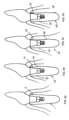
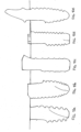
- Figs. 5b, 5c and 5d Several examples of flattened portions of different lengths are shown in Figs. 5b, 5c and 5d , shown alongside a conventional prior art implant in Fig. 5a .
- the topology of the cutaway portion of the implant head may be designed in any one of a variety of ways.
- the smaller periphery portion may be flat or planar, or it can be curved.
- the narrow periphery portion can have the same surface topology as the remainder of the head of the implant, for example, with microthreads or rings for improved adhesion to bone and tissue.
- the smaller periphery head portion may extend to include any part of the implant's length up to its entire length.
- more than one longitudinal cutaway portion may be provided, preferably arranged symmetrically around the body.
- Fig. 6a is an isometric view
- FIG. 7a is a top view of an implant 20 having two cut away portions 22, 24, one opposite the other.
- This type of implant is particularly suitable where the bone ridge is narrow, for example, in the posterior mandible. See, for example, Fig. 8b , showing a cross-section of a posterior mandible 26 with a mandibular nerve canal 27.
- An implant 20 having cut away portions 22, 24 is implanted therein.
- the body of the implant remains of conventional size to retain the mechanical strength of the fixture and of the connection in the bone, but the head has a smaller periphery to provide narrow emergence in the buccal/lingual dimension, which permits minimum bone loss around the implant head and enhanced soft tissue response.
- an enlarged area 28 of bone buccal to the implant head and an enlarged area 29 of bone lingual to the implant head relative to conventional implants are obtained.
- Fig. 6b shows an isometric view
- Fig. 7b shows a top view of an implant 30 having three cutouts 32, 34, 36 equidistant about the longitudinal axis of the implant.
- This type of implant is particularly suitable for use with adjacent implants, particularly in areas where there is low bond volume buccal to the implant heads and between the implants.
- This design is particularly advantageous in the anterior part of upper jaw. See, for example, Fig. 8a , showing an occlusal view of an anterior maxillary bone crest 31 wherein two adjacent teeth 33 have been replaced with implants, after healing of the bone.
- Two implants 30 having cut away portions 32, 34, 36 are implanted in place of the two removed teeth.
- an enlarged area 35 of bone buccal to the implant heads and an enlarged area 37 of bone between the implant heads is provided, relative to conventional cylindrical (not cut away) implants.
- the screw receiving bore for connecting the abutment is not concentric with the longitudinal axis of the implant. This permits the periphery of the implant head to be even smaller than in the symmetrical implant according to the invention described above.
- Fig. 6c shows an isometric view
- Fig. 7c shows a top view of an implant 40 having a single cutout 42, similar to the implant of Fig. 4 , but having an eccentrically disposed screw receiving bore 44 substantially aligned with the longitudinal axis of the implant.
- This design provides an implant having an even larger cutout area than the concentric implant of Fig. 4 , particularly useful in areas where it is desired to provide extra (maximum) bone volume.
- Fig. 6d shows an isometric view
- Fig. 7d shows a top view of an implant 50 having a single cutout 52, similar to the implant of Fig. 6c , having a screw receiving bore 54 non-concentrically disposed relative to the longitudinal axis of the implant.
- the screw receiving bore 54 is not aligned with the longitudinal axis of the implant but rather is formed at an angle thereto, as best seen in Fig. 7d .
- This design is particularly useful in the anterior region of the upper jaw to ensure extra volume of buccal bone and lingual access to the abutment screw. See, for example, Fig.
- connection and screw hole centers can be positioned more lingually (away from the cutout 52 ) and they can be oriented so as to greatly increase the probability that the abutment screw could be accessed from the lingual aspect 59 of the restoration.
- Figs. 9a, 9b , 9c and 9d provide side sectional illustrations of the various angular possibilities.
- Fig. 9a shows an implant 60 with a cutaway 62 and a screw receiving bore 64 concentrically located and aligned with respect to the longitudinal axis of the implant.
- Fig. 9b shows an implant 65 with a cutaway 66 and a screw receiving bore 68 concentrically located but tilted at an angle with respect to the longitudinal axis of the implant.
- Fig. 9a, 9b , 9c and 9d provide side sectional illustrations of the various angular possibilities.
- Fig. 9a shows an implant 60 with a cutaway 62 and a screw receiving bore 64 concentrically located and aligned with respect to the longitudinal axis of the implant.
- Fig. 9b shows an implant 65 with a cutaway 66 and a screw receiving bore 68 concentrically located but tilted at an angle with respect to the longitudinal axis of the implant.
- FIG. 9c shows an implant 70 with a cutaway 72 and a screw receiving bore 74 eccentrically located but aligned with respect to the longitudinal axis of the implant.
- the cut away portion 72 is enlarged in width, relative to the implant of Fig. 9a .
- Fig. 9d shows an implant 75 with a cutaway 76 and a screw receiving bore 78 eccentrically located and tilted at an angle with respect to the longitudinal axis of the implant.
- the cut away portion 76 can be enlarged in width, relative to the implant of Fig. 9b . It will be appreciated that any of these screw-receiving bore options can be used with any of the designs of implants described above and below and with any of the types of implants desired.
- the particular design of the implant can be selected according to the location in the patient's mouth and the state of the patient's jaw.
- the modified head design disclosed in the present invention can be applied to all implant designs, regardless of body shape, thread type, length, diameter, connection, surface treatment and material used, or whether it is a bone level, tissue level or one-piece implant. See, for example, Figs. 10a - 10e , each illustrating a different type or design of implant implementing the cutaway portion.
- Fig. 10a and Figs. 10b illustrate bone level implants.
- 10c illustrates a tissue level implant.
- Fig. 10d illustrates a bone level implant with an external connection and
- Fig. 10e illustrates a one-piece implant, having a prosthetic integrally formed with the implant body.
- An implant with a single flattened or cut away area will have a single most proper (optimal) orientation (i.e., with the cut away area oriented adjacent the thin bone portion of the jaw).
- This type of implant, with a single cut away portion has a single proper orientation within a full 360 degree of rotational insertion and is better suited for smaller step, tighter thread implants or non-threaded implants.
- this characteristic may be a detriment in the case of threaded implants with a large thread step. While that may not be a problem in the anterior region where sub-bone-level positioning is often carried out, when this is an issue, the heads of the implants could be made with two or three cutouts, as illustrated above, so as to provide two-way or three-way symmetry.
- the implant can be rotated until any one of several cutout portions is disposed facing the problematic area of the jaw, so that additional bone growth will be possible in that area.
- These embodiments of the invention allow for smaller depth variability.
- a two cutout implant head allows two proper positions within every full rotation and a three cutout implant head allows three proper positions within every full rotation.
- an implant incorporating the new design with the non concentric implant head requires a particular positioning of the implant head so that the cutout is always directed toward the area with reduced bone volume. Many times that would be towards the buccal. It will be appreciated that this particular positioning allows for non symmetry in the location and angulation of the abutment connection and its screw relative to the implant, as described above.
- connection and the top surface of the implant could be made to suit the particular needs of such implant-abutment pair better than the conventional types of implant-abutment connections.
- FIGs. 11a, 11b and 11c Three exemplary instances of such a connection, having different features for receiving complementary features on the abutment, are depicted in Figs. 11a, 11b and 11c .
- the head defines a protrusion
- Fig. 11b the head defines a flattened portion with notches
- Fig. 11c the head defines a rectangular connection.
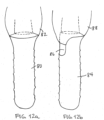
- FIG. 12a A further advantage of the implants is illustrated schematically in Figs. 12a , showing a prior art implant 80 with a prosthetic unit 82, and an implant 84, illustrated in Fig. 12b , according to one example.
- Implant 84 has a single cutaway 86 as described above.
- Prior art implant 80 is a tissue level implant where bone and tissue loss may occur. When it does, the metal implant 80 becomes visible. That may be very disturbing, particularly if located in the anterior portion of the mouth.
- the implant 84 of the present invention permits the prosthetic crown 88 to be extended along part or all of the length of the cut away portion 86. This portion is disposed to be visible in the mouth, so that even if there is some bone or tissue loss, the metal implant 84 will not be visible.
Description
- The present invention relates to the field of dental implants and, more particularly, to the design of the implant's head that maximizes long term stability of the hard and soft tissues surrounding the implant, the abutment and the prosthesis connected to it.
- In this context reference is made to
WO 2005/065571 A1 which discloses a dental implant having two opposing cutouts at the implant head. - Dental implants are used to replace teeth that have been lost. An implant is placed in the jaw bone at the site of the missing tooth and a dental prosthetic unit is attached to it. The long term functional and aesthetic success of dental implants, and the prostheses attached to them, is determined by the response of the hard and soft tissues around them. Throughout the history of the art of dental implantology, it has been known that some bone loss and subsequent soft tissue recession always occur and have to be accepted.
- In recent years, it has been shown that bone loss and soft tissue loss can be lessened by improving the tissue environment around the head of the implant and its connection with the prosthetic unit. Several implant designs having reduced connection diameter provided more soft tissue volume above the implant head and around the prosthetic abutment and have shown better hard and soft tissue responses. See, for example, the conventional,
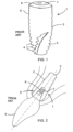
prior art implant 1 shown inFig. 1 and shown, in use, inFig. 2 .Implant 1 includes abody 2 having a root-like apex 3, typically withscrew threads 4 around the outside surface, and animplant head 5 having atop surface 6. Ascrew receiving bore 7 is defined inbody 2 for receiving the prosthetic unit, typically an abutment having anabutment screw 8 and acrown 9 mounted on the abutment - However, bone loss still occurs where there is less bone thickness around the implant head. This effect is most evident, and results in the most disturbing outcome, when it occurs in the thin bone plates buccal to implants placed in the anterior region of the mouth where the tissues are exposed in the smile, as well as between adjacent implants, particularly in the anterior region. Dental professionals go to great lengths to prevent this effect by trying to locate the implant head away from the buccal plate, thus attempting to allow more bone thickness buccal to the implant head. But bone ridge size and implant dimensions may hinder their success.
- Similarly, when adjacent implants are required, it may be difficult to leave sufficient space between the implants to permit the required tissue volume.
- It is an established clinical fact that thicker buccal bone and larger bone volume are associated with reduced bone loss and reduced soft tissue loss. For that reason, smaller diameter implants are sometimes used in the anterior region of the mouth but at the expense of sacrificing mechanical strength of the fixture and of the connection or sacrificing prosthetic flexibility (such as when using one piece implants).
- In addition, it is sometimes of great practical advantage to be able to directly access the abutment-to-implant connection screw through the crown unit. However, in the anterior maxillary regions, where it may be most desired to access from the lingual (palatal) direction, it is, in many cases, not possible due to the anatomy, size and orientation of the bone ridge (as seen in
Fig. 2 ). To compensate for the angular limitations when restoring implants in the anterior maxillary region dentists sometimes resort to cemented crown solutions or use of angle-correcting prosthetic parts for screw retained crowns, which could sacrifice the preferred geometry of the sub-gingival prosthetic unit, the aesthetic outcome and connection strength (as by requiring smaller diameter screws). - Accordingly, there is a long felt need for a dental implant which results in reduced bone and soft tissue loss and which can be more successfully implanted in more problematic situations.
- The present invention solves this problem by providing a modified head portion on the dental implant that allows more bone volume in critical locations around the implant head. At the same time, the mechanical strength of the implant and of the connection is maintained by retaining the remainder of the implant unchanged with reference to conventional implants. In this way, bone resorption and gum recession in critical areas around dental implants can be reduced.
- There is thus provided, in accordance with the present invention, a dental implant as defined in
claim 1. - According to one embodiment of the invention, the dental implant further includes a screw receiving bore extending downwards from the top surface for coupling an abutment to the implant. The screw receiving bore may be concentric with the longitudinal axis of the implant, it may be non-concentric with the longitudinal axis of the implant, and/or it may be formed at an angle relative to the longitudinal axis of the implant.
- According to the invention, the implant is a one-piece implant and the cut away portion extends along at least part of the intrabony portion and may include the trans-mucosal portion of the implant.
- According to some embodiments, the cutaway portion is tapered. According to others, the cutaway portion ends in a shoulder. According to still others, the cutaway portion extends along the entire length of the body.
- According to the invention there are three cutaway portions longitudinally extending downwardly from the top surface, equidistant around the body and outwardly to the periphery.
- In an example not forming part of the claimed invention, a method of forming a dental implant is disclosed, the method including forming an implant body having a top surface; and cutting away at least one non-annular portion longitudinally extending downwardly from the top surface along one side of the body and outwardly to the periphery.
- In another example not forming part of the claimed invention, a method of forming a dental implant is disclosed, the method including providing a substantially cylindrical or conical implant body having a longitudinal axis; and forming a head portion having a top surface on the body. The head portion is formed by cutting away a portion of the periphery of the head portion so that the head portion has a non-circular periphery that is smaller than the periphery of the body.
- The present invention will be further understood and appreciated from the following detailed description taken in conjunction with the drawings in which:
-
Fig. 1 is a schematic illustration of a prior art dental implant head; -
Fig. 2 is a schematic sectional illustration of the prior art dental implant ofFig. 1 in use; -
Fig. 3 is a schematic illustration of a dental implant not forming part of the claimed invention; -
Fig. 4 is an isometric view of the implant head of the dental implant ofFig. 3 ; -
Fig. 5a is a schematic sectional view of a conventional prior art implant in use; -
Figs. 5b, 5c and 5d are schematic sectional views of implants not forming part of the claimed invention having flattened portions of different lengths; -
Figs. 6a, 6b, 6c and 6d are isometric views of implants having different arrangements of cutaway portions wherein onlyfig. 6b shows an implant according to the claimed invention; -
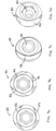
Figs. 7a, 7b, 7c and 7d are top views of the implants ofFigs. 6a, 6b, 6c and 6d ; -
Figs. 8a, 8b and8c are schematic illustrations of three exemplary embodiments of implants according to the invention, in use; -
Figs. 9a to 9d are side sectional illustrations of implants; -
Figs. 10a to 10e are side sectional views of implants of varying size and design, all formed according to different examples not forming part of the claimed invention; -
Figs. 11a to 11c are schematic illustrations of implant heads not forming part of the claimed invention; -
Fig. 12a is a schematic of a conventional prior art implant head with prosthetic unit; and -
Fig. 12b is a schematic illustration of a dental implant not forming part of the claimed invention. It will be appreciated that the drawings are only schematic and are not to scale. - The present invention relates to a dental implant with a modified head portion that allows more bone in critical locations around the implant head without sacrificing the mechanical strength of the implant and of the connection. An object of the present invention is to reduce bone resorption in critical areas around dental implants by employing this modified design of the head of the implant.
- The new design involves providing an implant having a body and an integrally formed head of substantially smaller periphery than the periphery of the body, where the periphery of the head is not annular. The implant includes an implant body having a top surface from which one or more parts of the circumference of the predominantly tubular shape of the implant body are cut away from the top surface down to a desired height. The flattened surface allows more bone thickness adjacent to it, as compared to an implant having a full contour tubular shape, as the cutaway area becomes filled with new bone growth. The gain in bone thickness in critical areas, such as where there is a thin buccal bone plate or a thin mandibular ridge or between adjacent implants, is substantial and results in a lower risk of bone resorption and the consequent aesthetic compromise.
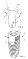
- One example of an
implant 10 is shown in cross-section inFig. 3 , and in an isometric view inFig. 4 .Implant 10 includes animplant body 11 and animplant head 12 defining atop portion 13.Head 12 has a longitudinal,non-annular cutaway portion 14, extending downwards fromtop portion 13 and outwards to the periphery of the implant. The result is that thehead 12 has a smaller periphery than the body.Implant 10 also includes a screw receiving bore 15 for receiving an abutment screw (not shown) to hold a prosthetic unit 17. Thecutaway portion 14 of theimplant head 12 is indicated in broken lines inFig. 3 , to show the substantial difference in periphery of the head produced by the cut awayportion 14. The cutaway portion can extend along the length of the implant as far as desired and may be parallel to the longitudinal axis of the implant or tapered at an angle to the longitudinal axis or may end in ashoulder 16, as in the example Illustrated inFig. 3 . Several examples of flattened portions of different lengths are shown inFigs. 5b, 5c and 5d , shown alongside a conventional prior art implant inFig. 5a . - It should be noted that the topology of the cutaway portion of the implant head may be designed in any one of a variety of ways. The smaller periphery portion may be flat or planar, or it can be curved. If desired, the narrow periphery portion can have the same surface topology as the remainder of the head of the implant, for example, with microthreads or rings for improved adhesion to bone and tissue. As stated above, the smaller periphery head portion may extend to include any part of the implant's length up to its entire length. In addition, more than one longitudinal cutaway portion may be provided, preferably arranged symmetrically around the body. For example,
Fig. 6a is an isometric view andFig. 7a is a top view of animplant 20 having two cut awayportions Fig. 8b , showing a cross-section of aposterior mandible 26 with amandibular nerve canal 27. Animplant 20 having cut awayportions enlarged area 28 of bone buccal to the implant head and anenlarged area 29 of bone lingual to the implant head relative to conventional implants are obtained. -
Fig. 6b shows an isometric view andFig. 7b shows a top view of animplant 30 having threecutouts Fig. 8a , showing an occlusal view of an anteriormaxillary bone crest 31 wherein twoadjacent teeth 33 have been replaced with implants, after healing of the bone. Twoimplants 30 having cut awayportions enlarged area 35 of bone buccal to the implant heads and anenlarged area 37 of bone between the implant heads is provided, relative to conventional cylindrical (not cut away) implants. - According to certain embodiments of the invention, the screw receiving bore for connecting the abutment is not concentric with the longitudinal axis of the implant. This permits the periphery of the implant head to be even smaller than in the symmetrical implant according to the invention described above.
Fig. 6c shows an isometric view andFig. 7c shows a top view of animplant 40 having asingle cutout 42, similar to the implant ofFig. 4 , but having an eccentrically disposed screw receiving bore 44 substantially aligned with the longitudinal axis of the implant. This design provides an implant having an even larger cutout area than the concentric implant ofFig. 4 , particularly useful in areas where it is desired to provide extra (maximum) bone volume. -
Fig. 6d shows an isometric view andFig. 7d shows a top view of animplant 50 having asingle cutout 52, similar to the implant ofFig. 6c , having a screw receiving bore 54 non-concentrically disposed relative to the longitudinal axis of the implant. However, inFig. 6d , the screw receiving bore 54 is not aligned with the longitudinal axis of the implant but rather is formed at an angle thereto, as best seen inFig. 7d . This design is particularly useful in the anterior region of the upper jaw to ensure extra volume of buccal bone and lingual access to the abutment screw. See, for example,Fig. 8c , where animplant 50 is shown, which has a screw receiving bore 54 having an axis 56 disposed at an angle to thelongitudinal axis 58 ofimplant 50. It will be appreciated that this particular positioning allows for non symmetry in the location and angulation of the abutment connection and its screw relative to the implant. Thus, the connection and screw hole centers can be positioned more lingually (away from the cutout 52) and they can be oriented so as to greatly increase the probability that the abutment screw could be accessed from thelingual aspect 59 of the restoration. - The connection itself (the interface between implant and abutment) could be tilted and in line with the tilted screw or, alternatively, the connection could be kept parallel to the longitudinal axis of the implant with just the screw hole and screw access tilted toward the lingual:
Figs. 9a, 9b ,9c and 9d provide side sectional illustrations of the various angular possibilities.Fig. 9a shows animplant 60 with acutaway 62 and a screw receiving bore 64 concentrically located and aligned with respect to the longitudinal axis of the implant.Fig. 9b shows animplant 65 with acutaway 66 and a screw receiving bore 68 concentrically located but tilted at an angle with respect to the longitudinal axis of the implant.Fig. 9c shows animplant 70 with acutaway 72 and a screw receiving bore 74 eccentrically located but aligned with respect to the longitudinal axis of the implant. Thus, the cut awayportion 72 is enlarged in width, relative to the implant ofFig. 9a . AndFig. 9d shows animplant 75 with acutaway 76 and a screw receiving bore 78 eccentrically located and tilted at an angle with respect to the longitudinal axis of the implant. Thus, the cut awayportion 76 can be enlarged in width, relative to the implant ofFig. 9b . It will be appreciated that any of these screw-receiving bore options can be used with any of the designs of implants described above and below and with any of the types of implants desired. - Thus, it will be appreciated that the particular design of the implant can be selected according to the location in the patient's mouth and the state of the patient's jaw.
- It will be appreciated that the modified head design disclosed in the present invention can be applied to all implant designs, regardless of body shape, thread type, length, diameter, connection, surface treatment and material used, or whether it is a bone level, tissue level or one-piece implant. See, for example,
Figs. 10a - 10e , each illustrating a different type or design of implant implementing the cutaway portion.Fig. 10a and Figs. 10b illustrate bone level implants. 10c illustrates a tissue level implant.Fig. 10d illustrates a bone level implant with an external connection andFig. 10e illustrates a one-piece implant, having a prosthetic integrally formed with the implant body. - An implant with a single flattened or cut away area will have a single most proper (optimal) orientation (i.e., with the cut away area oriented adjacent the thin bone portion of the jaw). This type of implant, with a single cut away portion has a single proper orientation within a full 360 degree of rotational insertion and is better suited for smaller step, tighter thread implants or non-threaded implants. However, this characteristic may be a detriment in the case of threaded implants with a large thread step. While that may not be a problem in the anterior region where sub-bone-level positioning is often carried out, when this is an issue, the heads of the implants could be made with two or three cutouts, as illustrated above, so as to provide two-way or three-way symmetry. In this way, the implant can be rotated until any one of several cutout portions is disposed facing the problematic area of the jaw, so that additional bone growth will be possible in that area. These embodiments of the invention allow for smaller depth variability. A two cutout implant head allows two proper positions within every full rotation and a three cutout implant head allows three proper positions within every full rotation.
- Similarly, proper, advantageous use of an implant incorporating the new design with the non concentric implant head (with just one cutout portion) requires a particular positioning of the implant head so that the cutout is always directed toward the area with reduced bone volume. Many times that would be towards the buccal. It will be appreciated that this particular positioning allows for non symmetry in the location and angulation of the abutment connection and its screw relative to the implant, as described above.
- It should be noted that since the non concentric implant and the screw access are directionally confined, it is no longer necessary to adhere to rotational symmetry in the connection. Instead, the connection and the top surface of the implant could be made to suit the particular needs of such implant-abutment pair better than the conventional types of implant-abutment connections. Three exemplary instances of such a connection, having different features for receiving complementary features on the abutment, are depicted in
Figs. 11a, 11b and 11c . InFig. 11a , the head defines a protrusion, inFig. 11b , the head defines a flattened portion with notches, and inFig. 11c , the head defines a rectangular connection. - A further advantage of the implants is illustrated schematically in
Figs. 12a , showing a prior art implant 80 with aprosthetic unit 82, and animplant 84, illustrated inFig. 12b , according to one example.Implant 84 has asingle cutaway 86 as described above. Prior art implant 80 is a tissue level implant where bone and tissue loss may occur. When it does, the metal implant 80 becomes visible. That may be very disturbing, particularly if located in the anterior portion of the mouth. Theimplant 84 of the present invention permits theprosthetic crown 88 to be extended along part or all of the length of the cut awayportion 86. This portion is disposed to be visible in the mouth, so that even if there is some bone or tissue loss, themetal implant 84 will not be visible.
Claims (8)
- A dental implant (10, 30) comprising:a body portion (11) and a head portion (12) integrally formed with said body portion (11); said body portion (11) having a periphery and said head portion (12) having a non-circular periphery; three cutouts (32, 34, 36) longitudinally extending downwards from a top surface of said head portion (12);wherein the non-circular periphery of said head portion is smaller than the periphery of the body portion; and wherein said three cutouts (32, 34, 36) provide a three-way symmetry to said non-circular periphery of said head portion (12).
- The dental implant according to claim 1, wherein said three cutouts (32, 34, 36) of said head portion (12) extend along a length of said body portion (11).
- The dental implant according to claim 1, wherein said non-circular periphery is curved.
- The dental implant according to claim 1, wherein said three cutouts (32, 34, 36) generate a circumference of the non-circular periphery of said head portion (12) that is smaller than a circumference of the periphery of said body portion (11).
- The dental implant according to claim 1, wherein said dental implant further comprises a screw receiving bore (15, 44, 54, 64, 74, 78) extending downwards from the top surface for coupling an abutment to the implant.
- The dental implant according to anyone of claims 1-5, wherein said body portion (11) is substantially cylindrical or conical.
- The dental implant according to anyone of claims 5-6, wherein said bore (15, 44, 54, 64, 74, 78) is formed at an angle to a longitudinal axis of the implant.
- The dental implant according to claim 1, wherein said implant comprises a prosthetic integrally formed with said implant body.
Applications Claiming Priority (3)
| Application Number | Priority Date | Filing Date | Title |
|---|---|---|---|
| US201161492382P | 2011-06-02 | 2011-06-02 | |
| PCT/IL2012/000218 WO2012164560A1 (en) | 2011-06-02 | 2012-06-03 | Dental implant |
| EP12793774.6A EP2713939B1 (en) | 2011-06-02 | 2012-06-03 | Dental implant |
Related Parent Applications (2)
| Application Number | Title | Priority Date | Filing Date |
|---|---|---|---|
| EP12793774.6A Division EP2713939B1 (en) | 2011-06-02 | 2012-06-03 | Dental implant |
| PCT/IL2012/000218 Previously-Filed-Application WO2012164560A1 (en) | 2011-06-02 | 2012-06-03 | Dental implant |
Publications (2)
| Publication Number | Publication Date |
|---|---|
| EP3682843A1 EP3682843A1 (en) | 2020-07-22 |
| EP3682843B1 true EP3682843B1 (en) | 2023-04-05 |
Family
ID=47258485
Family Applications (2)
| Application Number | Title | Priority Date | Filing Date |
|---|---|---|---|
| EP19191143.7A Active EP3682843B1 (en) | 2011-06-02 | 2012-06-03 | Dental implant |
| EP12793774.6A Active EP2713939B1 (en) | 2011-06-02 | 2012-06-03 | Dental implant |
Family Applications After (1)
| Application Number | Title | Priority Date | Filing Date |
|---|---|---|---|
| EP12793774.6A Active EP2713939B1 (en) | 2011-06-02 | 2012-06-03 | Dental implant |
Country Status (11)
| Country | Link |
|---|---|
| US (2) | US10441386B2 (en) |
| EP (2) | EP3682843B1 (en) |
| JP (1) | JP6133849B2 (en) |
| KR (1) | KR102085066B1 (en) |
| CN (1) | CN103717175A (en) |
| BR (1) | BR112013030990B1 (en) |
| ES (2) | ES2948570T3 (en) |
| IL (1) | IL254322B (en) |
| PT (2) | PT2713939T (en) |
| RU (1) | RU2612487C2 (en) |
| WO (1) | WO2012164560A1 (en) |
Families Citing this family (34)
| Publication number | Priority date | Publication date | Assignee | Title |
|---|---|---|---|---|
| PL2566413T3 (en) | 2010-05-05 | 2017-07-31 | Holger Zipprich | Dental implant |
| DE102010051176A1 (en) | 2010-11-15 | 2012-05-16 | Urs Brodbeck | Dental implant system and method for producing a dental implant system |
| DE102011009906A1 (en) * | 2011-01-31 | 2012-08-02 | Holger Zipprich | Dental implant system |
| EP2502600A1 (en) | 2011-03-21 | 2012-09-26 | Biodenta Swiss AG | Dental implant system |
| KR102085066B1 (en) | 2011-06-02 | 2020-03-05 | 엠아이에스 임플란츠 테크놀러지스 리미티드 | Dental implant |
| JP6049422B2 (en) * | 2012-11-27 | 2016-12-21 | 京セラメディカル株式会社 | Dental implant fixture and dental implant |
| ITLI20130001A1 (en) * | 2013-01-08 | 2014-07-09 | Roberto Malasoma | OSTEOINTEGRATED DENTAL PLANT CONTRADDISTING FROM AN OBLIQUE BORDER BETWEEN A ROUGH AND SMOOTH SURFACE |
| TWI583359B (en) | 2013-02-22 | 2017-05-21 | 巴科納 包瑞斯 Ds | Endosseous dental implant and abutment for prevention of bone loss |
| JP2017506122A (en) * | 2014-02-20 | 2017-03-02 | エムアイエス インプランツ テクノロジーズ リミテッド | Dental implant |
| US11090138B2 (en) | 2014-08-29 | 2021-08-17 | Fereidoun Daftary | Dental implant system and method |
| US10292792B2 (en) * | 2014-08-29 | 2019-05-21 | Nobel Biocare Services Ag | Restoration dental implant and method |
| AU2015311605B2 (en) * | 2014-09-05 | 2020-08-06 | Greg Miller | A dental implant |
| EP3267933A4 (en) * | 2015-03-11 | 2018-10-17 | Nobel Biocare Services AG | Restoration dental implant system and method |
| WO2017129828A1 (en) * | 2016-01-29 | 2017-08-03 | Nobel Biocare Services Ag | Dentistry tool |
| CN108601635B (en) | 2016-01-29 | 2021-10-08 | 诺贝尔生物服务公司 | Dental implant, insertion tool for a dental implant and combination of a dental implant and an insertion tool |
| ES2773198T3 (en) | 2016-01-29 | 2020-07-09 | Nobel Biocare Services Ag | Dental implant |
| USD783825S1 (en) | 2016-02-05 | 2017-04-11 | Silvio Franco Emanuelli | Post part for a dental implant |
| USD783822S1 (en) | 2016-02-05 | 2017-04-11 | Silvio Franco Emanuelli | Root part for a dental implant |
| USD783823S1 (en) | 2016-02-05 | 2017-04-11 | Silvio Franco Emanuelli | Post part for a dental implant |
| USD783826S1 (en) | 2016-02-05 | 2017-04-11 | Silvio Franco Emanuelli | Root part for a dental implant |
| USD783824S1 (en) | 2016-02-05 | 2017-04-11 | Silvio Franco Emanuelli | Root part for a dental implant |
| USD785179S1 (en) | 2016-02-05 | 2017-04-25 | Silvio Franco Emanuelli | Post part for a dental implant |
| US10987201B2 (en) * | 2016-02-23 | 2021-04-27 | Paltop Advanced Dental Solutions Ltd. | Dental implant |
| AU2017286777C1 (en) | 2016-06-14 | 2022-04-14 | Southern Implants (Pty) Ltd | Dental implant having reverse-tapered main body for anterior post-extraction sockets |
| IL247473A0 (en) * | 2016-08-24 | 2016-12-29 | Ilia Musheev | Implant with integrated scan body |
| KR101731542B1 (en) * | 2016-10-05 | 2017-05-02 | 주식회사 트루어버트먼트코리아 | A fixture for implant |
| KR101916210B1 (en) * | 2017-01-13 | 2019-01-30 | 주식회사 덴플렉스 | Dental implant |
| IL310554A (en) * | 2018-02-21 | 2024-03-01 | Southern Implants Pty Ltd | Asymmetric zygomatic dental implant with partial micro thread/groove |
| US20210236247A1 (en) * | 2018-05-03 | 2021-08-05 | João Manuel MENDES CARAMÊS | Medical implant and medical implant system for malar process of the maxilla |
| DE102018113237A1 (en) * | 2018-06-04 | 2019-12-05 | TRI Dental Implants Int. AG | Dental implant and denture |
| US10987196B2 (en) | 2018-06-27 | 2021-04-27 | Paltop Advanced Dental Solutions Ltd. | Drill guide |
| US11452583B2 (en) * | 2019-01-10 | 2022-09-27 | Paramvir Singh | Dental implant evaluation unit |
| BR202019001133U2 (en) * | 2019-01-21 | 2020-08-04 | Jjgc Indústria E Comércio De Materiais Dentários S.A. | ZYGOMATIC IMPLANT WITH PARTIALLY INTERRUPTED THREADED PORTION |
| WO2022132118A1 (en) * | 2020-12-14 | 2022-06-23 | Борис Михайлович СИМАНОВСКИЙ | Dental implant |
Family Cites Families (52)
| Publication number | Priority date | Publication date | Assignee | Title |
|---|---|---|---|---|
| FR2508307A1 (en) * | 1981-09-16 | 1982-12-31 | Lonca Philippe | NEW DENTAL IMPLANTS AND ANCILLARY EQUIPMENT FOR THEIR IMPLEMENTATION |
| JP2725194B2 (en) * | 1988-12-16 | 1998-03-09 | 株式会社アドバンス | Artificial root |
| JP2605165B2 (en) * | 1990-06-13 | 1997-04-30 | 分吉 東 | Artificial root |
| WO1992020306A1 (en) * | 1991-05-24 | 1992-11-26 | Kerry Zang | Bone fastening device |
| US5454811A (en) * | 1993-11-08 | 1995-10-03 | Smith & Nephew Dyonics, Inc. | Cam lock orthopedic fixation screw and method |
| AU6610196A (en) | 1995-08-17 | 1997-03-12 | Institut Straumann Ag | Device for holding small screws using an elastically clamping ring |
| US5785525A (en) * | 1996-05-17 | 1998-07-28 | Weissman; Bernard | Dental implant system |
| US6001100A (en) * | 1997-08-19 | 1999-12-14 | Bionx Implants Oy | Bone block fixation implant |
| US6039568A (en) | 1998-06-02 | 2000-03-21 | Hinds; Kenneth F. | Tooth shaped dental implants |
| IT1313580B1 (en) | 1999-07-26 | 2002-09-09 | Ioannis Corcolis | DENTAL IMPLANT DEVICE. |
| US20060078847A1 (en) * | 2000-09-29 | 2006-04-13 | Kwan Norman H | Dental implant system and additional methods of attachment |
| GB0108551D0 (en) | 2001-04-05 | 2001-05-23 | Osseobiotek Ltd | Implant |
| GB0123804D0 (en) * | 2001-10-04 | 2001-11-21 | Osseobiotek Ltd | Implant |
| US6953463B2 (en) * | 2001-10-12 | 2005-10-11 | Hs West Investments, Llc | Interference screws having increased proximal diameter |
| US6723099B1 (en) * | 2001-11-08 | 2004-04-20 | Biomet, Inc. | Three sided tack for bone fixation |
| US7291012B2 (en) * | 2003-02-27 | 2007-11-06 | Lyren Philip S | Dental implant with porous body |
| IL156033A0 (en) * | 2003-05-21 | 2004-03-28 | Ophir Fromovich Ophir Fromovic | Dental implant |
| DE50309926D1 (en) | 2003-10-16 | 2008-07-10 | Straumann Holding Ag | Improved transmission part for an implant |
| ITMI20032618A1 (en) * | 2003-12-30 | 2005-06-30 | Ioannis Corcolis | DENTAL IMPLANT |
| US20060003290A1 (en) | 2004-07-01 | 2006-01-05 | Niznick Gerald A | Endosseous one-piece screw-type dental implants |
| US7300282B2 (en) * | 2004-07-16 | 2007-11-27 | Sapian Schubert L | Biofunctional dental implant |
| DE202005005421U1 (en) * | 2005-04-05 | 2006-08-10 | Dinkelacker, Wolfgang, Dr.med.dent. | Helical dental implant |
| ES2351277T3 (en) | 2005-08-03 | 2011-02-02 | Straumann Holding Ag | CLAMPING ELEMENT FOR A DENTAL IMPLANT. |
| AT502881B1 (en) * | 2005-10-05 | 2007-08-15 | Pirker Wolfgang Ddr | DENTAL IMPLANT |
| EP1882458A1 (en) * | 2006-07-27 | 2008-01-30 | Straumann Holding AG | Dental implant |
| DE202007018746U1 (en) | 2007-01-12 | 2009-03-19 | Zl Microdent-Attachment Gmbh & Co. Kg | Wrench and holding element for a screwing tool |
| US7806693B2 (en) * | 2007-04-23 | 2010-10-05 | Nobel Biocare Services Ag | Dental implant |
| WO2008157137A1 (en) * | 2007-06-14 | 2008-12-24 | Southern Implants, Inc. | Dental implant system for use with coaxially non-aligned prosthesis |
| WO2008157138A2 (en) * | 2007-06-14 | 2008-12-24 | Southern Implants, Inc. | Dental implant for asymmetrical abutment mounting |
| UA27037U (en) * | 2007-06-19 | 2007-10-10 | Dental implant | |
| WO2009015103A1 (en) * | 2007-07-20 | 2009-01-29 | Cochlear Americas | Coupling apparatus for a bone anchored hearing device |
| US8066511B2 (en) * | 2008-03-18 | 2011-11-29 | Woehrle Peter | Asymmetrical dental implant |
| KR100931996B1 (en) * | 2008-05-19 | 2009-12-15 | 오스템임플란트 주식회사 | Dental Implant Fixtures |
| DE102009060656A1 (en) | 2008-12-22 | 2010-08-12 | Neumeyer, Stefan, Dr. | Spreader for spreading bone structures |
| DE102008063397B4 (en) * | 2008-12-30 | 2019-02-21 | Holger Zipprich | Dental implant screw |
| USD616097S1 (en) * | 2009-09-15 | 2010-05-18 | 3M Innovative Properties Company | Dental implant abutment |
| JP5814255B2 (en) * | 2009-12-11 | 2015-11-17 | ヴェルチェロッティ,トマソ | Dental intraosseous implant |
| EP2444023A1 (en) | 2010-10-20 | 2012-04-25 | Astra Tech AB | A dental component, a dental fixture, a dental implant assembly and a dental implant system |
| KR101050236B1 (en) | 2010-12-20 | 2011-07-19 | 정효경 | Tool device driver |
| EP2510899A1 (en) * | 2011-04-14 | 2012-10-17 | Astra Tech AB | Fixture |
| KR102085066B1 (en) | 2011-06-02 | 2020-03-05 | 엠아이에스 임플란츠 테크놀러지스 리미티드 | Dental implant |
| WO2012173577A1 (en) | 2011-06-13 | 2012-12-20 | Haydar Imad | Oval section dental implant |
| EP2570097A1 (en) | 2011-09-14 | 2013-03-20 | Dentsply IH AB | A dental component, a dental fixture and a dental implant |
| EP2570095A1 (en) | 2011-09-14 | 2013-03-20 | Dentsply IH AB | A dental component and a dental implant |
| JP5512626B2 (en) | 2011-10-03 | 2014-06-04 | ワイ.エス.ハング ウィリアム | Dental implant |
| US20140030674A1 (en) | 2012-01-27 | 2014-01-30 | Hao Nguyen | Prefabricated immediate no-drill dental implant |
| US9119688B2 (en) | 2012-03-01 | 2015-09-01 | Straumann Holding Ag | Holding device for dental implant |
| KR101457011B1 (en) | 2012-04-06 | 2014-11-04 | 오상훈 | Guide apparatus for Dental implant pixture and drilling method using it |
| JP5813080B2 (en) * | 2013-12-11 | 2015-11-17 | 本田技研工業株式会社 | Backpack power sprayer |
| DE102014118723A1 (en) | 2013-12-17 | 2015-06-18 | Epiphanostics GmbH | Enossal single-tooth implant |
| JP2017506122A (en) | 2014-02-20 | 2017-03-02 | エムアイエス インプランツ テクノロジーズ リミテッド | Dental implant |
| KR101594095B1 (en) * | 2014-03-05 | 2016-02-15 | 주식회사 이비아이 | Fixture for dental implant to contain blood easily |
-
2012
- 2012-06-03 KR KR1020137035023A patent/KR102085066B1/en active IP Right Grant
- 2012-06-03 RU RU2013158082A patent/RU2612487C2/en active
- 2012-06-03 JP JP2014513308A patent/JP6133849B2/en active Active
- 2012-06-03 CN CN201280037636.2A patent/CN103717175A/en active Pending
- 2012-06-03 ES ES19191143T patent/ES2948570T3/en active Active
- 2012-06-03 ES ES12793774T patent/ES2753967T3/en active Active
- 2012-06-03 EP EP19191143.7A patent/EP3682843B1/en active Active
- 2012-06-03 PT PT127937746T patent/PT2713939T/en unknown
- 2012-06-03 US US14/123,289 patent/US10441386B2/en active Active
- 2012-06-03 WO PCT/IL2012/000218 patent/WO2012164560A1/en active Application Filing
- 2012-06-03 PT PT191911437T patent/PT3682843T/en unknown
- 2012-06-03 EP EP12793774.6A patent/EP2713939B1/en active Active
- 2012-06-03 BR BR112013030990-3A patent/BR112013030990B1/en active IP Right Grant
-
2017
- 2017-09-04 IL IL254322A patent/IL254322B/en unknown
-
2019
- 2019-09-19 US US16/575,467 patent/US20200078146A1/en active Pending
Also Published As
| Publication number | Publication date |
|---|---|
| EP2713939A1 (en) | 2014-04-09 |
| RU2013158082A (en) | 2015-07-20 |
| WO2012164560A1 (en) | 2012-12-06 |
| JP2014516721A (en) | 2014-07-17 |
| ES2753967T3 (en) | 2020-04-15 |
| IL254322B (en) | 2021-12-01 |
| ES2948570T3 (en) | 2023-09-14 |
| PT2713939T (en) | 2019-11-29 |
| JP6133849B2 (en) | 2017-05-24 |
| KR102085066B1 (en) | 2020-03-05 |
| US20200078146A1 (en) | 2020-03-12 |
| BR112013030990A2 (en) | 2016-11-29 |
| RU2612487C2 (en) | 2017-03-09 |
| US20140106305A1 (en) | 2014-04-17 |
| EP3682843A1 (en) | 2020-07-22 |
| PT3682843T (en) | 2023-06-22 |
| KR20150035351A (en) | 2015-04-06 |
| EP2713939A4 (en) | 2014-12-03 |
| IL254322A0 (en) | 2017-11-30 |
| EP2713939B1 (en) | 2019-08-21 |
| CN103717175A (en) | 2014-04-09 |
| BR112013030990B1 (en) | 2020-12-22 |
| US10441386B2 (en) | 2019-10-15 |
Similar Documents
| Publication | Publication Date | Title |
|---|---|---|
| EP3682843B1 (en) | Dental implant | |
| US7845945B2 (en) | Anchoring element for use in bone | |
| JP5275460B2 (en) | Medical implant and method of implantation | |
| CA2766927C (en) | Modified asymmetrical dental implant | |
| KR20110033853A (en) | Improved fixture of two-piece dental implant | |
| JP2008511350A (en) | Dental implant system and method for implantation and implantation of an implant system | |
| KR100807150B1 (en) | Implant for overdenture | |
| EP3453358B1 (en) | Improved tissue level implant | |
| US20130045462A1 (en) | Dental implant fixing system | |
| EP3593752A1 (en) | Dental implant, connecting screw and kit for implantation | |
| US10682208B2 (en) | Abutment assembly and manufacturing method thereof | |
| CN105101906B (en) | One-piece or multi-piece planting system having a mounting element with one or more outer rings | |
| WO2012109405A2 (en) | Narrowed implant body | |
| EP2229912A1 (en) | Dental implant | |
| KR200392276Y1 (en) | Dental Implant | |
| KR200392241Y1 (en) | Dental Temporary Implant | |
| JPWO2011125309A1 (en) | Dental implant | |
| IL229758A (en) | Dental implant | |
| KR20210071682A (en) | Abutment assembly and method for assembling the same | |
| JP7465620B2 (en) | Self-tapping implant fixture | |
| JP7305283B2 (en) | Implant fixture with tapered thread groove depth | |
| WO2011056323A2 (en) | Variably mountable implant with stepped socket |
Legal Events
| Date | Code | Title | Description |
|---|---|---|---|
| PUAI | Public reference made under article 153(3) epc to a published international application that has entered the european phase |
Free format text: ORIGINAL CODE: 0009012 |
|
| STAA | Information on the status of an ep patent application or granted ep patent |
Free format text: STATUS: REQUEST FOR EXAMINATION WAS MADE |
|
| 17P | Request for examination filed |
Effective date: 20190809 |
|
| AC | Divisional application: reference to earlier application |
Ref document number: 2713939 Country of ref document: EP Kind code of ref document: P |
|
| AK | Designated contracting states |
Kind code of ref document: A1 Designated state(s): AL AT BE BG CH CY CZ DE DK EE ES FI FR GB GR HR HU IE IS IT LI LT LU LV MC MK MT NL NO PL PT RO RS SE SI SK SM TR |
|
| REG | Reference to a national code |
Ref country code: HK Ref legal event code: DE Ref document number: 40032812 Country of ref document: HK |
|
| STAA | Information on the status of an ep patent application or granted ep patent |
Free format text: STATUS: EXAMINATION IS IN PROGRESS |
|
| 17Q | First examination report despatched |
Effective date: 20210531 |
|
| GRAP | Despatch of communication of intention to grant a patent |
Free format text: ORIGINAL CODE: EPIDOSNIGR1 |
|
| STAA | Information on the status of an ep patent application or granted ep patent |
Free format text: STATUS: GRANT OF PATENT IS INTENDED |
|
| INTG | Intention to grant announced |
Effective date: 20221020 |
|
| GRAS | Grant fee paid |
Free format text: ORIGINAL CODE: EPIDOSNIGR3 |
|
| GRAA | (expected) grant |
Free format text: ORIGINAL CODE: 0009210 |
|
| STAA | Information on the status of an ep patent application or granted ep patent |
Free format text: STATUS: THE PATENT HAS BEEN GRANTED |
|
| AC | Divisional application: reference to earlier application |
Ref document number: 2713939 Country of ref document: EP Kind code of ref document: P |
|
| AK | Designated contracting states |
Kind code of ref document: B1 Designated state(s): AL AT BE BG CH CY CZ DE DK EE ES FI FR GB GR HR HU IE IS IT LI LT LU LV MC MK MT NL NO PL PT RO RS SE SI SK SM TR |
|
| REG | Reference to a national code |
Ref country code: GB Ref legal event code: FG4D |
|
| REG | Reference to a national code |
Ref country code: DE Ref legal event code: R096 Ref document number: 602012079454 Country of ref document: DE |
|
| REG | Reference to a national code |
Ref country code: CH Ref legal event code: EP |
|
| REG | Reference to a national code |
Ref country code: AT Ref legal event code: REF Ref document number: 1557693 Country of ref document: AT Kind code of ref document: T Effective date: 20230415 |
|
| REG | Reference to a national code |
Ref country code: IE Ref legal event code: FG4D |
|
| P01 | Opt-out of the competence of the unified patent court (upc) registered |
Effective date: 20230509 |
|
| REG | Reference to a national code |
Ref country code: PT Ref legal event code: SC4A Ref document number: 3682843 Country of ref document: PT Date of ref document: 20230622 Kind code of ref document: T Free format text: AVAILABILITY OF NATIONAL TRANSLATION Effective date: 20230616 |
|
| REG | Reference to a national code |
Ref country code: SE Ref legal event code: TRGR Ref country code: LT Ref legal event code: MG9D |
|
| PGFP | Annual fee paid to national office [announced via postgrant information from national office to epo] |
Ref country code: RO Payment date: 20230529 Year of fee payment: 12 Ref country code: PT Payment date: 20230622 Year of fee payment: 12 Ref country code: FR Payment date: 20230510 Year of fee payment: 12 Ref country code: DE Payment date: 20230502 Year of fee payment: 12 |
|
| REG | Reference to a national code |
Ref country code: NL Ref legal event code: MP Effective date: 20230405 |
|
| REG | Reference to a national code |
Ref country code: ES Ref legal event code: FG2A Ref document number: 2948570 Country of ref document: ES Kind code of ref document: T3 Effective date: 20230914 |
|
| REG | Reference to a national code |
Ref country code: AT Ref legal event code: MK05 Ref document number: 1557693 Country of ref document: AT Kind code of ref document: T Effective date: 20230405 |
|
| PG25 | Lapsed in a contracting state [announced via postgrant information from national office to epo] |
Ref country code: NL Free format text: LAPSE BECAUSE OF FAILURE TO SUBMIT A TRANSLATION OF THE DESCRIPTION OR TO PAY THE FEE WITHIN THE PRESCRIBED TIME-LIMIT Effective date: 20230405 |
|
| PGFP | Annual fee paid to national office [announced via postgrant information from national office to epo] |
Ref country code: BE Payment date: 20230517 Year of fee payment: 12 |
|
| PG25 | Lapsed in a contracting state [announced via postgrant information from national office to epo] |
Ref country code: NO Free format text: LAPSE BECAUSE OF FAILURE TO SUBMIT A TRANSLATION OF THE DESCRIPTION OR TO PAY THE FEE WITHIN THE PRESCRIBED TIME-LIMIT Effective date: 20230705 Ref country code: AT Free format text: LAPSE BECAUSE OF FAILURE TO SUBMIT A TRANSLATION OF THE DESCRIPTION OR TO PAY THE FEE WITHIN THE PRESCRIBED TIME-LIMIT Effective date: 20230405 |
|
| PGFP | Annual fee paid to national office [announced via postgrant information from national office to epo] |
Ref country code: IT Payment date: 20230710 Year of fee payment: 12 Ref country code: GB Payment date: 20230504 Year of fee payment: 12 Ref country code: ES Payment date: 20230830 Year of fee payment: 12 Ref country code: CH Payment date: 20230702 Year of fee payment: 12 |
|
| PG25 | Lapsed in a contracting state [announced via postgrant information from national office to epo] |
Ref country code: RS Free format text: LAPSE BECAUSE OF FAILURE TO SUBMIT A TRANSLATION OF THE DESCRIPTION OR TO PAY THE FEE WITHIN THE PRESCRIBED TIME-LIMIT Effective date: 20230405 Ref country code: PL Free format text: LAPSE BECAUSE OF FAILURE TO SUBMIT A TRANSLATION OF THE DESCRIPTION OR TO PAY THE FEE WITHIN THE PRESCRIBED TIME-LIMIT Effective date: 20230405 Ref country code: LV Free format text: LAPSE BECAUSE OF FAILURE TO SUBMIT A TRANSLATION OF THE DESCRIPTION OR TO PAY THE FEE WITHIN THE PRESCRIBED TIME-LIMIT Effective date: 20230405 Ref country code: LT Free format text: LAPSE BECAUSE OF FAILURE TO SUBMIT A TRANSLATION OF THE DESCRIPTION OR TO PAY THE FEE WITHIN THE PRESCRIBED TIME-LIMIT Effective date: 20230405 Ref country code: IS Free format text: LAPSE BECAUSE OF FAILURE TO SUBMIT A TRANSLATION OF THE DESCRIPTION OR TO PAY THE FEE WITHIN THE PRESCRIBED TIME-LIMIT Effective date: 20230805 Ref country code: HR Free format text: LAPSE BECAUSE OF FAILURE TO SUBMIT A TRANSLATION OF THE DESCRIPTION OR TO PAY THE FEE WITHIN THE PRESCRIBED TIME-LIMIT Effective date: 20230405 Ref country code: GR Free format text: LAPSE BECAUSE OF FAILURE TO SUBMIT A TRANSLATION OF THE DESCRIPTION OR TO PAY THE FEE WITHIN THE PRESCRIBED TIME-LIMIT Effective date: 20230706 Ref country code: AL Free format text: LAPSE BECAUSE OF FAILURE TO SUBMIT A TRANSLATION OF THE DESCRIPTION OR TO PAY THE FEE WITHIN THE PRESCRIBED TIME-LIMIT Effective date: 20230405 |
|
| PGFP | Annual fee paid to national office [announced via postgrant information from national office to epo] |
Ref country code: SE Payment date: 20230510 Year of fee payment: 12 |
|
| PG25 | Lapsed in a contracting state [announced via postgrant information from national office to epo] |
Ref country code: FI Free format text: LAPSE BECAUSE OF FAILURE TO SUBMIT A TRANSLATION OF THE DESCRIPTION OR TO PAY THE FEE WITHIN THE PRESCRIBED TIME-LIMIT Effective date: 20230405 |
|
| REG | Reference to a national code |
Ref country code: DE Ref legal event code: R097 Ref document number: 602012079454 Country of ref document: DE |
|
| PG25 | Lapsed in a contracting state [announced via postgrant information from national office to epo] |
Ref country code: SK Free format text: LAPSE BECAUSE OF FAILURE TO SUBMIT A TRANSLATION OF THE DESCRIPTION OR TO PAY THE FEE WITHIN THE PRESCRIBED TIME-LIMIT Effective date: 20230405 |
|
| PG25 | Lapsed in a contracting state [announced via postgrant information from national office to epo] |
Ref country code: MC Free format text: LAPSE BECAUSE OF FAILURE TO SUBMIT A TRANSLATION OF THE DESCRIPTION OR TO PAY THE FEE WITHIN THE PRESCRIBED TIME-LIMIT Effective date: 20230405 |
|
| PG25 | Lapsed in a contracting state [announced via postgrant information from national office to epo] |
Ref country code: SM Free format text: LAPSE BECAUSE OF FAILURE TO SUBMIT A TRANSLATION OF THE DESCRIPTION OR TO PAY THE FEE WITHIN THE PRESCRIBED TIME-LIMIT Effective date: 20230405 Ref country code: SK Free format text: LAPSE BECAUSE OF FAILURE TO SUBMIT A TRANSLATION OF THE DESCRIPTION OR TO PAY THE FEE WITHIN THE PRESCRIBED TIME-LIMIT Effective date: 20230405 Ref country code: MC Free format text: LAPSE BECAUSE OF FAILURE TO SUBMIT A TRANSLATION OF THE DESCRIPTION OR TO PAY THE FEE WITHIN THE PRESCRIBED TIME-LIMIT Effective date: 20230405 Ref country code: EE Free format text: LAPSE BECAUSE OF FAILURE TO SUBMIT A TRANSLATION OF THE DESCRIPTION OR TO PAY THE FEE WITHIN THE PRESCRIBED TIME-LIMIT Effective date: 20230405 Ref country code: DK Free format text: LAPSE BECAUSE OF FAILURE TO SUBMIT A TRANSLATION OF THE DESCRIPTION OR TO PAY THE FEE WITHIN THE PRESCRIBED TIME-LIMIT Effective date: 20230405 Ref country code: CZ Free format text: LAPSE BECAUSE OF FAILURE TO SUBMIT A TRANSLATION OF THE DESCRIPTION OR TO PAY THE FEE WITHIN THE PRESCRIBED TIME-LIMIT Effective date: 20230405 |
|
| PLBE | No opposition filed within time limit |
Free format text: ORIGINAL CODE: 0009261 |
|
| STAA | Information on the status of an ep patent application or granted ep patent |
Free format text: STATUS: NO OPPOSITION FILED WITHIN TIME LIMIT |
|
| PG25 | Lapsed in a contracting state [announced via postgrant information from national office to epo] |
Ref country code: LU Free format text: LAPSE BECAUSE OF NON-PAYMENT OF DUE FEES Effective date: 20230603 |
|
| 26N | No opposition filed |
Effective date: 20240108 |
|
| REG | Reference to a national code |
Ref country code: IE Ref legal event code: MM4A |
|
| PG25 | Lapsed in a contracting state [announced via postgrant information from national office to epo] |
Ref country code: LU Free format text: LAPSE BECAUSE OF NON-PAYMENT OF DUE FEES Effective date: 20230603 |
|
| PG25 | Lapsed in a contracting state [announced via postgrant information from national office to epo] |
Ref country code: IE Free format text: LAPSE BECAUSE OF NON-PAYMENT OF DUE FEES Effective date: 20230603 |