EP3682841B2 - Dentales wurzelkanalinstrument - Google Patents
Dentales wurzelkanalinstrument Download PDFInfo
- Publication number
- EP3682841B2 EP3682841B2 EP20152244.8A EP20152244A EP3682841B2 EP 3682841 B2 EP3682841 B2 EP 3682841B2 EP 20152244 A EP20152244 A EP 20152244A EP 3682841 B2 EP3682841 B2 EP 3682841B2
- Authority
- EP
- European Patent Office
- Prior art keywords
- root canal
- core
- region
- canal instrument
- slope
- Prior art date
- Legal status (The legal status is an assumption and is not a legal conclusion. Google has not performed a legal analysis and makes no representation as to the accuracy of the status listed.)
- Active
Links
Images

Classifications
-
- A—HUMAN NECESSITIES
- A61—MEDICAL OR VETERINARY SCIENCE; HYGIENE
- A61C—DENTISTRY; APPARATUS OR METHODS FOR ORAL OR DENTAL HYGIENE
- A61C5/00—Filling or capping teeth
- A61C5/40—Implements for surgical treatment of the roots or nerves of the teeth; Nerve needles; Methods or instruments for medication of the roots
- A61C5/42—Files for root canals; Handgrips or guiding means therefor
Definitions
- the present invention relates to a dental root canal instrument for treating a root canal of a tooth.
- Root canal instruments are state of the art, for example from DE 202012012526 U1 Root canal instruments must have a certain flexibility in order to be able to follow the curves and turns of the root canal in order to be able to carry out a corresponding root canal treatment. Molars in particular can have a relatively complicated root canal system in which the root canal instrument must also follow small radii of the root canal. This must ensure sufficient flexibility of the root canal instrument. Therefore, root canal instruments have a core, i.e. a solid material core, starting from a tip of the root canal instrument, which continuously widens conically in the direction of a shaft area of the root canal instrument. The core of the root canal instrument has a very small diameter in cross-section at the tip, which continuously widens.
- a slope of the core runs over the entire length of the shaft area parallel to a slope of an outer envelope curve of the cutting edges of the cutting area. Furthermore, the DE 20 2012 012526 U1 and the WO 99/43469 A1 a root canal instrument according to the preamble of claim 1.
- the dental root canal instrument according to the invention with the features of claim 1 has the advantage that the root canal instrument has excellent flexibility.
- the bends and turns of the root canal can be followed excellently with the root canal instrument according to the invention.
- Dead or infected pulp tissue can thus be completely removed from the root canal with a high degree of reliability.
- the root canal can be prepared in a conical manner, with the narrowest point being at the apical end point of the root canal.
- the root canal instrument has a shaft area and a cutting area with at least one cutting edge and a core.
- the core (solid material core) of the root canal instrument is the area inside the root canal instrument around which the cutting edges and chip receiving grooves of the root canal instrument are guided. An envelope curve of the cutting edges runs from a tip to the
- the core of the cutting region has at least one core region which has a second slope in the direction of the shaft region of the root canal instrument, which is smaller than the first slope.
- the second slope of the core is smaller than the first slope of the envelope curve of the cutting edges.
- Root canal instruments usually have cores which widen conically in the direction of the shaft region with the same slope as the envelope curve of the cutting edges.
- the core widening in the direction of the shaft region with a small slope means that the root canal instrument has greater flexibility, in particular in the part of the cutting region which is closer to the shaft region.
- the core rises in stages towards the shaft region.
- One or more steps can be provided, the slopes at the respective step regions always being smaller than the slope of the envelope curve of the cutting edges.
- the core widens at a first conical region from the tip to a first point P1, which is spaced from the tip towards the shaft region, in the direction of the shaft region conically with the second slope. From the first point P1 to the shaft region, a second conical region with a slope with a third angle ⁇ is provided, the third angle ⁇ being smaller than the second angle ⁇ .
- the core thus has two different slopes starting from the tip towards the shaft region, whereby a degree of flexibility of the root canal instrument can be adjusted.
- a transition between the gradually increasing areas of the core is edge-free. This results in a continuous transition between the gradually increasing areas of the core.
- the pitch of the core decreases by at least 75%, preferably at least 90%, from the tip to the shaft area.
- the pitch of the core is 1° at the tip and 0.1° at the transition to the shaft area, so that the pitch of the core is reduced by 90%.
- An axial distance between the tip and the point P1, from which the slope of the core of the root canal instrument is reduced is preferably in a range of 10% to 30% of a total axial length L of the cutting area and is particularly preferably 20% of the total length L of the cutting area.
- the first angle ⁇ of the first slope of the envelope curve of the cutting edges is in a range of 0.1° ⁇ ⁇ ⁇ 2° and in particular in a range of 0.5° ⁇ ⁇ ⁇ 1.1°.
- the second angle ⁇ of the second slope of the core is then correspondingly smaller.
- the second conical region of the core has a second length and an axial direction of the root canal instrument which is equal to or greater than 50% of the total length of the cutting region.
- the root canal instrument further preferably comprises a cutting area with exactly two cutting edges. Alternatively, exactly three or exactly four cutting edges are provided.
- the cutting edges are particularly preferably S-shaped in cross section.
- chip grooves are provided between the cutting edges of the cutting area of the root canal instrument, the depth of which increases continuously from the tip of the root canal instrument to the shaft area. This ensures optimal removal of material in the root canal that has been removed by the root canal instrument.
- a width of the chip grooves between the cutting edges of the cutting area also increases continuously from the tip to the shaft area.
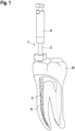
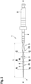
- the dental root canal instrument 1 As from Fig.2 As can be seen, the dental root canal instrument 1 according to the first embodiment comprises a shaft region 2, a cutting region 3 and a connecting piece 8.
- the connecting piece 8 serves for connection to a drive or a handpiece with which a dentist can operate the root canal instrument.
- the cutting area 3 provided with cutting edges runs from a tip 7 of the root canal instrument to the shaft area 2.
- the cutting area 3 has a total length L in the axial direction X-X of the root canal instrument.
- the cutting area 3 has exactly two cutting edges 5, 6, which wind in a spiral shape in the longitudinal direction of the root canal instrument. This creates chip grooves 9 between the two cutting edges 5, 6, which continuously expand from the tip 7 in the direction of the shaft area 2 in terms of both a width 90 and a depth T. This ensures that removed material is safely removed from the root canal.
- Fig.1 shows schematically the use of the root canal instrument 1 in a tooth 10, which is shown as a molar.
- a root canal 11 of the tooth 10 is curved. Since the root canals are individually very different, the root canal instrument 1 must have very good flexibility, as shown schematically in Fig.1 shown.
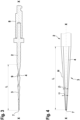
- the cutting area 3 also has a core 4 (solid material core) that runs from the tip 7 to the shaft area 2.
- the core 4 widens conically from the tip 7 of the root canal instrument to the shaft area 2.
- An envelope curve H of the two cutting edges 5, 6 also widens conically from the tip of the root canal instrument to the shaft area 2.
- the envelope curve H of the cutting edges expands with a first slope with a first angle a, which is larger than a second slope with a second angle ⁇ of the core 4. This can be seen in detail from Fig.4 visible.
- the envelope curves H of the cutting edges and the core 4 no longer run parallel and with the same gradient as in the prior art, but the gradient of the core 4 is smaller than that of the envelope curve H of the cutting edges.
- the flexibility of the root canal instrument in the shaft area 3 can thus be significantly increased in comparison with the state of the art.
- the cross sections of the core 4 and the cutting area 3 are shown schematically in the Fig. 2a to 2c
- the core 4 at section AA of Fig. 2a a first diameter D1.
- This first diameter D1 is smaller than a second diameter D2 at the intersection point BB of Fig. 2b .
- the second diameter D2 is smaller than a third diameter D3 at the intersection point CC of Fig. 2c .
- a diameter of the outer envelope curve H of the cutting edges with the larger first pitch increases significantly faster in the direction of the shaft area 2 than the diameter of the core 4.
- the two cones of the core 4 and the envelope curve H of the cutting edges form two cylindrical cones with the same height, which, however, have base areas of different sizes at the transition to the shaft area 2, since the pitch of the two straight circular cones is different.
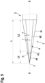
- Fig.5 shows schematically the structure of a root canal instrument according to a second example for explaining the present invention. Identical or functionally identical parts are designated with the same reference numerals.
- the second example corresponds essentially to the first example, whereby in contrast to the first example, the soul 4 in the second example is designed differently.
- the core 4 has a first conical region 41 which begins at the tip 7 and extends to a first point P1.
- the first conical area 41 is followed by a second conical area 42 of the core, which extends to the shaft area 2. As in Fig.5 As shown, a slope of the first and second conical region 41, 42 is different. The second angle ⁇ at the first conical region 41 is greater than a third angle ⁇ at the second conical region 42.
- the envelope curve H of the cutting edges 5, 6 runs conically continuously from the tip 7 to the shaft region 2 with the first angle a, as in the first embodiment. Thus, ⁇ > ⁇ > ⁇ .
- the flexibility of the dental instrument 1 can be varied over the total length L.
- the first conical region 41 runs over a length L1 in the axial direction XX of the root canal instrument and the second conical region 42 runs over a length L2.
- the length L2 is significantly greater than the length L1.
- the slightly larger slope with the second angle ⁇ on the first conical region 41 makes it possible in particular to avoid the dental instrument having a core that is too small and with too small a diameter in the area of the tip, which could lead to a risk of the dental instrument breaking in this area. This can be avoided by choosing the slope with the second angle ⁇ .
- the core of the second embodiment is thus composed of a truncated cone and a cone, with an edge-free transition between the cone and the truncated cone preferably being provided.
- further truncated cones with other jacket angles could be arranged.
- this embodiment corresponds to the previous embodiment, so that reference can be made to the description given there.
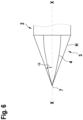
- Fig.6 shows a schematic view of a root canal instrument according to a third example, which, however, does not fall under the claims, to explain the present invention. Identical or functionally identical parts are again designated with the same reference numerals.
- the core in the third example which does not fall under the claims, has the shape of a paraboloid for explanation purposes.
- the envelope curve of the core 4 is thereby defined by a parabola rotated around the central axis.
- the slope of the core 4 thus decreases continuously from the tip 7 in the direction of the shaft region 2, but remains positive. It would also be possible for the paraboloid to change into a cylinder in the direction of the shaft region 2. This makes it possible to obtain a very flexible root canal instrument. Otherwise, this embodiment corresponds to the previous embodiments, so that reference can be made to the description given there.
Landscapes
- Health & Medical Sciences (AREA)
- Engineering & Computer Science (AREA)
- Biomedical Technology (AREA)
- Neurology (AREA)
- Neurosurgery (AREA)
- Nuclear Medicine, Radiotherapy & Molecular Imaging (AREA)
- Surgery (AREA)
- Oral & Maxillofacial Surgery (AREA)
- Dentistry (AREA)
- Epidemiology (AREA)
- Life Sciences & Earth Sciences (AREA)
- Animal Behavior & Ethology (AREA)
- General Health & Medical Sciences (AREA)
- Public Health (AREA)
- Veterinary Medicine (AREA)
- Dental Tools And Instruments Or Auxiliary Dental Instruments (AREA)
Description
- Die vorliegende Erfindung betrifft ein dentales Wurzelkanalinstrument zur Behandlung eines Wurzelkanals eines Zahns.
- Wurzelkanalinstrumente sind aus dem Stand der Technik beispielsweise aus der
DE 202012012526 U1 bekannt. Wurzelkanalinstrumente müssen dabei eine gewisse Flexibilität aufweisen, um den Bögen und Windungen des Wurzelkanals folgen zu können, um eine entsprechende Wurzelkanalbehandlung durchführen zu können. Insbesondere Backenzähne können hierbei ein relativ kompliziertes Wurzelkanalsystem aufweisen, bei dem das Wurzelkanalinstrument auch kleinen Radien des Wurzelkanals folgen muss. Hierdurch muss eine ausreichende Flexibilität des Wurzelkanalinstruments gewährleistet sein. Daher weisen Wurzelkanalinstrumente ausgehend von einer Spitze des Wurzelkanalinstruments eine Seele, d.h. einen Vollmaterial-Kern, auf, welcher sich kontinuierlich in Richtung zu einem Schaftbereich des Wurzelkanalinstruments konisch erweitert. Dabei weist die Seele des Wurzelkanalinstruments an der Spitze einen sehr kleinen Durchmesser im Querschnitt auf, welcher sich kontinuierlich erweitert. Eine Steigung der Seele verläuft dabei über die gesamte Länge des Schaftbereichs parallel zu einer Steigung einer äußeren Hüllkurve der Schneiden des Schneidenbereichs. Weiterhin zeigt dieDE 20 2012 012526 U1 und dieWO 99/43469 A1 - Es ist daher Aufgabe der vorliegenden Erfindung, ein dentales Wurzelkanalinstrument bereitzustellen, welches bei einfachem Aufbau und einfacher, kostengünstiger Herstellbarkeit eine verbesserte Flexibilität aufweist und insbesondere auch starken Windungen eines Wurzelkanals eines Zahns folgen kann.
- Diese Aufgabe wird durch ein dentales Wurzelkanalinstrument mit den Merkmalen des Anspruchs 1 gelöst. Die Unteransprüche zeigen bevorzugte Weiterbildungen der Erfindung.
- Das erfindungsgemäße dentale Wurzelkanalinstrument mit den Merkmalen des Anspruchs 1 weist den Vorteil auf, dass das Wurzelkanalinstrument eine exzellente Flexibilität aufweist. Dadurch kann bei der Behandlung eines Wurzelkanals den Bögen und Windungen des Wurzelkanals mit dem erfindungsgemäßen Wurzelkanalinstrument hervorragend gefolgt werden. Somit kann abgestorbenes oder infiziertes Pulpagewebe aus dem Wurzelkanal mit hoher Sicherheit vollständig entfernt werden. Dadurch gelingt eine weitestgehende Eliminierung von Mikroorganismen, welche sich im Wurzelkanal befinden. Weiterhin kann eine Präparation des Wurzelkanals in konischer Weise erfolgen, wobei die engste Stelle am apikalen Endpunkt des Wurzelkanals liegt. Dies wird erfindungsgemäß dadurch erreicht, dass das Wurzelkanalinstrument einen Schaftbereich und einen Schneidenbereich mit wenigstens einer Schneide und einer Seele aufweist. Die Seele (Vollmaterial-Kern) des Wurzelkanalinstruments ist dabei der Bereich im Inneren des Wurzelkanalinstruments, um welchen Schneiden und Spanaufnahmenuten des Wurzelkanalinstruments herum geführt sind. Eine Hüllkurve der Schneiden verläuft ausgehend von einer Spitze bis zum
- Schaftbereich mit einer ersten konstanten Steigung mit einem ersten Winkel α in einer sich konisch erweiternden Weise. Weiterhin weist die Seele des Schneidenbereichs wenigstens einen Seelenbereich auf, welcher in Richtung zum Schaftbereich des Wurzelkanalinstruments eine zweite Steigung, die kleiner ist als die erste Steigung, aufweist. Somit ist zumindest an einem Teilbereich, vorzugsweise an der vollständigen Seele, die zweite Steigung der Seele kleiner als die erste Steigung der Hüllkurve der Schneiden. Üblicherweise weisen Wurzelkanalinstrumente Seelen auf, welche sich in Richtung zum Schaftbereich konisch mit gleicher Steigung wie die Hüllkurve der Schneiden erweitern. Somit geht die vorliegende Erfindung einen vollständig anderen Weg als der Stand der Technik. Durch die sich in Richtung des Schaftbereichs mit geringer Steigung erweiternden Seele wird erreicht, dass das Wurzelkanalinstrument eine höhere Flexibilität, insbesondere an dem Teil des Schneidenbereichs, welcher näher in Richtung zum Schaftbereich liegt, aufweist.
- Gemäß der Erfindung steigt die Seele in Richtung zum Schaftbereich stufenweise an. Hierbei können eine oder mehrere Stufen vorgesehen werden, wobei die Steigungen an den jeweiligen Stufenbereichen immer kleiner sind wie die Steigung der Hüllkurve der Schneiden. Gemäß einer bevorzugten alternativen Ausgestaltung der Erfindung erweitert sich die Seele an einem ersten konischen Bereich von der Spitze zu einem ersten Punkt P1, der von der Spitze in Richtung zum Schaftbereich beabstandet ist, in Richtung zum Schaftbereich konisch mit der zweiten Steigung. Vom ersten Punkt P1 zum Schaftbereich ist ein zweiter konischer Bereich mit einer Steigung mit einem dritten Winkel γ vorgesehen, wobei der dritte Winkel γ kleiner ist als der zweite Winkel β. Somit weist die Seele ausgehend von der Spitze in Richtung zum Schaftbereich zwei unterschiedliche Steigungen auf, wodurch ein Grad der Flexibilität des Wurzelkanalinstruments eingestellt werden kann.
- Besonders bevorzugt ist ein Übergang zwischen den stufenweise ansteigenden Bereichen der Seele kantenfrei. Hierdurch wird ein kontinuierlicher Übergang zwischen den stufenweise ansteigenden Seelenbereichen erhalten.
- Vorzugsweise nimmt die Steigung der Seele von der Spitze bis zum Schaftbereich mindestens 75%, bevorzugt mindestens 90% ab. Beispielsweise beträgt die Steigung der Seele an der Spitze 1° und am Übergang zum Schaftbereich 0,1°, so dass sich die Steigung der Seele um 90% reduziert.
- Ein axialer Abstand zwischen der Spitze und dem Punkt P1, ab welchem sich die Steigung der Seele des Wurzelkanalinstruments reduziert, liegt vorzugsweise in einem Bereich von 10% bis 30% einer axialen Gesamtlänge L des Schneidenbereichs und beträgt besonders bevorzugt 20% der Gesamtlänge L des Schneidenbereichs.
- Vorzugsweise liegt der erste Winkel α der ersten Steigung der Hüllkurve der Schneiden in einem Bereich von 0,1° ≤ α ≤ 2° und insbesondere in einem Bereich von 0,5° ≤ α ≤ 1,1° liegt. Entsprechend kleiner ist dann der zweite Winkel β der zweiten Steigung der Seele. Vorzugsweise weist der zweite konische Bereich der Seele eine zweite Länge und eine Axialrichtung des Wurzelkanalinstruments auf, welche gleich oder größer 50% der Gesamtlänge des Schneidenbereichs ist.
- Weiter bevorzugt umfasst das Wurzelkanalinstrument einen Schneidenbereich mit genau zwei Schneiden. Alternativ sind genau drei oder genau vier Schneiden vorgesehen. Besonders bevorzugt sind die Schneiden im Querschnitt S-förmig.
- Vorzugsweise sind zwischen den Schneiden des Schneidenbereichs des Wurzelkanalinstruments Spannuten vorgesehen, deren Nuttiefe sich ausgehend von der Spitze des Wurzelkanalinstruments bis zum Schaftbereich kontinuierlich vergrößert. Hierdurch wird ein optimaler Abtransport von durch das Wurzelkanalinstrument entferntem Material im Wurzelkanal erreicht.
- Weiter bevorzugt vergrößert sich auch eine Breite der Spannuten zwischen den Schneiden des Schneidenbereichs von der Spitze bis zum Schaftbereich kontinuierlich.
- Nachfolgend werden bevorzugte Ausführungsbeispiele unter Bezugnahme auf die begleitende Zeichnung im Detail beschrieben., welche jedoch nicht das gekennzeichnete erfinderische Merkmal des Anspruchs 1 zeigen In der Zeichnung ist:
- Fig. 1
- eine schematische, teilweise geschnittene Ansicht eines Zahns mit einem dentalen Wurzelkanalinstrument gemäß einem ersten Beispiel, welches jedoch nicht unter die Ansprüche fällt, zur Erläuterung der Erfindung,
- Fig. 2
- eine schematische Seitenansicht des Wurzelkanalinstruments von
Figur 1 , - Fig. 2a
- eine Schnittansicht entlang der Linie A-A von
Figur 2 , - Fig. 2b
- eine Schnittansicht entlang der Linie B-B von
Figur 2 , - Fig. 2c
- eine Schnittansicht entlang der Linie C-C von
Figur 2 , - Fig. 3
- eine schematische Schnittansicht des Wurzelkanalinstruments von
Figur 2 , - Fig. 4
- eine schematische Darstellung von Steigungen der Hüllkurve der Schneiden und der Seele des Wurzelkanalinstruments des ersten Ausführungsbeispiels,
- Fig. 5
- eine schematische Darstellung von Steigungen der Hüllkurve der Schneiden und einer Seele eines Wurzelkanalinstruments gemäß einem zweiten Beispiel zur Erläuterung der Erfindung, und
- Fig. 6
- eine schematische Darstellung von Steigungen der Hüllkurve der Schneiden und einer Seele eines Wurzelkanalinstruments gemäß einem dritten Beispiel, welches jedoch nicht unter die Ansprüche fällt, zur Erläuterung der Erfindung.
- Nachfolgend wird unter Bezugnahme auf die
Fig. 1 bis 4 ein dentales Wurzelkanalinstrument 1 gemäß einem ersten Beispiel, welches jedoch nicht unter die Ansprüche fällt, zur Erläuterung der Erfindung im Detail beschrieben - Wie aus
Fig. 2 ersichtlich ist, umfasst das dentale Wurzelkanalinstrument 1 gemäß dem ersten Ausführungsbeispiel einen Schaftbereich 2, einen Schneidenbereich 3 sowie ein Anschlussstück 8. Das Anschlussstück 8 dient dabei zur Verbindung mit einem Antrieb oder auch einem Handstück, mit welchen ein Zahnarzt das Wurzelkanalinstrument bedienen kann. - Der mit Schneiden versehene Schneidenbereich 3 verläuft ausgehend von einer Spitze 7 des Wurzelkanalinstruments bis zum Schaftbereich 2.
- Der Schneidenbereich 3 weist dabei in Axialrichtung X-X des Wurzelkanalinstruments eine Gesamtlänge L auf. Der Schneidenbereich 3 weist genau zwei Schneiden 5, 6 auf, welche sich spiralförmig in Längsrichtung des Wurzelkanalinstruments winden. Hierbei ergeben sich zwischen den beiden Schneiden 5, 6 Spannuten 9, welche sich ausgehend von der Spitze 7 in Richtung zum Schaftbereich 2 sowohl hinsichtlich einer Breite 90 als auch einer Tiefe T kontinuierlich erweitern. Dadurch kann ein sicherer Abtransport von entferntem Material aus dem Wurzelkanal sichergestellt werden.
-
Fig. 1 zeigt dabei schematisch die Verwendung des Wurzelkanalinstruments 1 in einem Zahn 10, welcher als Backenzahn dargestellt ist. Ein Wurzelkanal 11 des Zahns 10 ist dabei gebogen. Da die Wurzelkanäle individuell sehr verschieden sind, muss das Wurzelkanalinstrument 1 eine sehr gute Flexibilität aufweisen, wie schematisch inFig. 1 gezeigt. - Der Schneidenbereich 3 weist ferner eine von der Spitze 7 bis zum Schaftbereich 2 durchgehende Seele 4 (Vollmaterial-Kern) auf. Die Seele 4 erweitert sich dabei von der Spitze 7 des Wurzelkanalinstruments konisch bis zum Schaftbereich 2. Ebenfalls erweitert sich eine Hüllkurve H der beiden Schneiden 5, 6, ausgehend von der Spitze des Wurzelkanalinstruments bis zum Schaftbereich 2 konisch.
- Wie in
Fig. 4 gezeigt, erweitert sich die Hüllkurve H der Schneiden jedoch mit einer ersten Steigung mit einem ersten Winkel a, welcher größer ist als eine zweite Steigung mit einem zweiten Winkel β der Seele 4. Dies ist im Detail ausFig. 4 ersichtlich. - Somit verlaufen die Hüllkurven H der Schneiden und der Seele 4 nicht mehr wie im Stand der Technik parallel und mit gleicher Steigung, sondern die Steigung der Seele 4 ist kleiner als die der Hüllkurve H der Schneiden. Dadurch ergibt sich insbesondere in dem Bereich des Schneidenbereichs 3, welcher näher zum Schaftbereich 2 liegt, eine erhöhte Flexibilität. Hierdurch kann das dentale Wurzelkanalinstrument 1 deutlich besser sehr starken Windungen und Bögen des Wurzelkanals 11 des Zahns folgen, als die bisher verwendeten Wurzelkanalinstrumente im Stand der Technik. Somit kann eine Flexibilität des Wurzelkanalinstruments im Schaftbereich 3 im Vergleich mit dem Stand der Technik deutlich erhöht werden.
- Die Querschnitte der Seele 4 bzw. des Schneidenbereichs 3 sind nochmal schematisch in den
Fig. 2a bis 2c dargestellt. Hierbei weist die Seele 4 am Schnitt A-A vonFig. 2a einen ersten Durchmesser D1 auf. Dieser erste Durchmesser D1 ist kleiner als ein zweiter Durchmesser D2 am Schnittpunkt B-B vonFig. 2b . Der zweite Durchmesser D2 ist kleiner als ein dritter Durchmesser D3 am Schnittpunkt C-C vonFig. 2c . Gleichzeitig vergrößert sich ein Durchmesser der äußeren Hüllkurve H der Schneiden mit der größeren ersten Steigung deutlich schneller in Richtung zum Schaftbereich 2 als die Durchmesser der Seele 4. Somit bilden die beiden Kegel der Seele 4 und der Hüllkurve H der Schneiden zwei Zylinderkegel mit gleicher Höhe, welche jedoch am Übergang zum Schaftbereich 2 unterschiedlich große Grundflächen aufweisen, da die Steigung der beiden geraden Kreiskegel unterschiedlich ist. -
Fig. 5 zeigt schematisch den Aufbau eines Wurzelkanalinstruments gemäß einem zweiten Beispiel zur Erläuterung der vorliegenden Erfindung. Gleiche bzw. funktional gleiche Teile sind dabei mit den gleichen Bezugszeichen bezeichnet. - Das zweite Beispiel entspricht im Wesentlichen dem ersten Beispiel, wobei im Unterschied zum ersten Beispiel beim zweiten Beispiel die Seele 4 unterschiedlich ausgestaltet ist. Wie aus
Fig. 5 ersichtlich ist, weist die Seele 4 einen ersten konischen Bereich 41 auf, welcher an der Spitze 7 beginnt und bis zu einem ersten Punkt P1 verläuft. - An den ersten konischen Bereich 41 schließt sich ein zweiter konischer Bereich 42 der Seele an, welcher bis zum Schaftbereich 2 verläuft. Wie in
Fig. 5 dargestellt, ist hierbei eine Steigung des ersten und zweiten konischen Bereichs 41, 42 unterschiedlich. Hierbei ist der zweite Winkel β am ersten konischen Bereich 41 größer als ein dritter Winkel γ am zweiten konischen Bereich 42. Die Hüllkurve H der Schneiden 5, 6 verläuft wie im ersten Ausführungsbeispiel konisch kontinuierlich von der Spitze 7 bis zum Schaftbereich 2 mit dem ersten Winkel a. Somit ist α > β > γ. - Durch das Vorsehen von zwei unterschiedlichen Steigungen an der Seele 4 mit unterschiedlichen Winkeln β und γ kann die Flexibilität des Dentalinstruments 1 über die Gesamtlänge L variiert werden. Im in
Fig. 5 gezeigten Ausführungsbeispiel verläuft der erste konische Bereich 41 über eine Länge L1 in Axialrichtung X-X des Wurzelkanalinstruments und der zweite konische Bereich 42 verläuft über eine Länge L2. Die Länge L2 ist dabei deutlich größer als die Länge L1. Durch die etwas größere Steigung mit dem zweiten Winkel β am ersten konischen Bereich 41 kann insbesondere vermieden werden, dass das Dentalinstrument im Bereich der Spitze eine zu kleine Seele mit zu kleinen Durchmessern aufweist, was eine Bruchgefahr des Dentalinstruments in diesem Bereich bewirken könnte. Durch die Wahl der Steigung mit dem zweiten Winkel β kann dies vermieden werden. Somit ist die Seele des zweiten Ausführungsbeispiels aus einem Kegelstumpf und einem Kegel zusammengesetzt, wobei vorzugsweise ein kantenfreier Übergang zwischen dem Kegel und dem Kegelstumpf vorgesehen ist. Alternativ könnten noch weitere Kegelstümpfe mit anderen Mantelwinkeln angeordnet werden. Ansonsten entspricht dieses Ausführungsbeispiel dem vorhergehenden Ausführungsbeispiel, so dass auf die dort gegebene Beschreibung verwiesen werden kann. -
Fig. 6 zeigt eine schematische Ansicht eines Wurzelkanalinstruments gemäß einem dritten Beispiel, welches jedoch nicht unter die Ansprüche fällt, zur Erläuterung der vorliegenden Erfindung. Gleiche bzw. funktional gleiche Teile sind wieder mit den gleichen Bezugszeichen bezeichnet. Wie ausFig. 6 ersichtlich ist, weist die Seele im dritten Beispiel, welches jedoch nicht unter die Ansprüche fällt, zur Erläuterung die Form eines Paraboloiden auf. Hierdurch ist die Hüllkurve der Seele 4 durch eine um die Mittelachse rotierte Parabel definiert. Somit nimmt die Steigung der Seele 4 ausgehend von der Spitze 7 in Richtung zum Schaftbereich 2 kontinuierlich ab, bleibt jedoch positiv. Dabei wäre es auch möglich, dass der Paraboloid in Richtung zum Schaftbereich 2 in einen Zylinder übergeht. Dadurch kann ein sehr flexibles Wurzelkanalinstrument erhalten werden. Ansonsten entspricht dieses Ausführungsbeispiel den vorhergehenden Ausführungsbeispielen, so dass auf die dort gegebene Beschreibung verwiesen werden kann. -
- 1
- dentales Wurzelkanalinstrument
- 2
- Schaftbereich
- 3
- Schneidenbereich
- 4
- Seele
- 5, 6
- Schneiden
- 7
- Spitze
- 8
- Anschlussstück
- 9
- Spannut
- 10
- Zahn
- 11
- Wurzelkanal
- 41
- erster konischer Bereich der Seele
- 42
- zweiter konischer Bereich der Seele
- 90
- Breite der Spannut
- D1
- erster Durchmesser der Seele
- D2
- zweiter Durchmesser der Seele
- D3
- dritter Durchmesser der Seele
- H
- Hüllkurve der Schneiden
- L
- Gesamtlänge des Schneidenbereichs
- L1
- erster konischer Bereich der Seele
- L2
- zweiter konischer Bereich der Seele
- P1
- erster Punkt
- T
- Tiefe der Spannut
- X-X
- Axialrichtung des Wurzelkanalinstruments
- α
- Winkel der Steigung der Hüllkurve
- β
- Winkel der Steigung der Seele
- γ
- kleinerer Winkel der Steigung der Seele
Claims (6)
- Dentales Wurzelkanalinstrument, umfassend- einen Schaftbereich (2) und- einen Schneidenbereich (3) mit Schneiden (5, 6) und einer Seele (4),- wobei sich eine Hüllkurve (H) der Schneiden (5, 6) des Schneidenbereichs (3) ausgehend von einer Spitze (7) in Richtung zum Schaftbereich (2) mit einer ersten Steigung mit einem ersten Winkel (α) konisch erweitert, und- wobei zumindest ein Bereich der Seele (4) des Schneidenbereichs (3) bis zum Schaftbereich (2) mit einer zweiten Steigung mit einem zweiten Winkel (γ) ansteigt, wobei der zweite Winkel (γ) kleiner ist als der erste Winkel (α).- dadurch gekennzeichnet, dass die Seele (4) ausgehend von der Spitze (7) in Richtung zum Schaftbereich (2) stufenweise ansteigt,- wobei die Seele (4) einen ersten konischen Bereich (42) und einen zweiten konischen Bereich (41) aufweist, wobei der zweite konische Bereich (41) eine Steigung mit einem dritten Winkel (β) aufweist, welche größer ist als die Steigung des ersten konischen Bereichs (42) mit dem zweiten Winkel (γ).
- Wurzelkanalinstrument nach Anspruch 1, wobei ein Übergang zwischen den stufenweise ansteigenden Bereichen der Seele (4) kantenfrei ausgebildet ist.
- Wurzelkanalinstrument nach einem der vorhergehenden Ansprüche, wobei die Steigung der Seele (4) von der Spitze (7) bis zum Schaftbereich (2) zwischen um mindestens 75% abnimmt.
- Wurzelkanalinstrument nach einem der vorhergehenden Ansprüche, wobei der erste Winkel (α) der ersten Steigung der Hüllkurve (H) der Schneiden in einem Bereich von 0,1° ≤ α ≤ 2° liegt und insbesondere in einem Bereich von 0,5° ≤ α ≤ 1,1° liegt, und/oder wobei der dritte Winkel (β) der Steigung der Seele (4) kleiner 0,5°, insbesondere kleiner 0,2° ist.
- Wurzelkanalinstrument nach einem der vorhergehenden Ansprüche, wobei der Schneidenbereich (3) genau zwei Schneiden oder genau drei Schneiden oder genau vier Schneiden aufweist.
- Wurzelkanalinstrument nach einem der vorhergehenden Ansprüche, wobei zwischen den Schneiden (5, 6) Spannuten (9) vorgesehen sind, deren Nuttiefe (T) sich ausgehend von der Spitze zum Schaftbereich (2) kontinuierlich vergrößert und/oder wobei sich eine Breite (90) der Spannuten (9) von der Spitze (7) zum Schaftbereich (2) kontinuierlich vergrößert.
Priority Applications (1)
| Application Number | Priority Date | Filing Date | Title |
|---|---|---|---|
| PL20152244.8T PL3682841T5 (pl) | 2019-01-17 | 2020-01-16 | Dentystyczne narzędzie do kanału korzenia |
Applications Claiming Priority (1)
| Application Number | Priority Date | Filing Date | Title |
|---|---|---|---|
| DE102019101174.4A DE102019101174A1 (de) | 2019-01-17 | 2019-01-17 | Dentales Wurzelkanalinstrument |
Publications (3)
| Publication Number | Publication Date |
|---|---|
| EP3682841A1 EP3682841A1 (de) | 2020-07-22 |
| EP3682841B1 EP3682841B1 (de) | 2021-10-13 |
| EP3682841B2 true EP3682841B2 (de) | 2024-09-11 |
Family
ID=69174421
Family Applications (1)
| Application Number | Title | Priority Date | Filing Date |
|---|---|---|---|
| EP20152244.8A Active EP3682841B2 (de) | 2019-01-17 | 2020-01-16 | Dentales wurzelkanalinstrument |
Country Status (5)
| Country | Link |
|---|---|
| US (1) | US12357425B2 (de) |
| EP (1) | EP3682841B2 (de) |
| DE (1) | DE102019101174A1 (de) |
| ES (1) | ES2902429T5 (de) |
| PL (1) | PL3682841T5 (de) |
Families Citing this family (1)
| Publication number | Priority date | Publication date | Assignee | Title |
|---|---|---|---|---|
| US11628042B1 (en) | 2022-03-07 | 2023-04-18 | William B. Johnson | Endodontic instrument with enlarged chip space and reduced torque strength |
Family Cites Families (35)
| Publication number | Priority date | Publication date | Assignee | Title |
|---|---|---|---|---|
| US4332561A (en) * | 1979-08-03 | 1982-06-01 | Inventive Technology International, Inc. | Dental file |
| US4538989A (en) * | 1979-10-01 | 1985-09-03 | Dentsply International, Inc. | Dental reamer |
| FR2587197A1 (fr) * | 1985-09-13 | 1987-03-20 | Reynaud Marc | Tenon d'ancrage d'une prothese dentaire dans la racine d'une dent |
| US4934934A (en) * | 1988-11-04 | 1990-06-19 | Quality Dental Products, Inc. | Dental file/reamer instrument |
| US5106298A (en) * | 1991-04-03 | 1992-04-21 | Heath Derek E | Endodontic dental instrument |
| US6206695B1 (en) * | 1994-02-14 | 2001-03-27 | Nelson J. Wong | Step-back eliminating tapered dental cutting instruments for improved root canal treatment and method |
| US5653590A (en) * | 1995-06-06 | 1997-08-05 | Tulsa Dental Products, L.L.C. | Kit of endodontic instruments and method of utilizing same |
| US5713736A (en) * | 1996-05-01 | 1998-02-03 | Tulsa Dental Products, L.L.C. | Endodontic dental instrument |
| US5882198A (en) * | 1997-03-28 | 1999-03-16 | Ormco Corporation | Endodontic instrument having enhanced compliance at the tip |
| US5857852A (en) * | 1997-11-19 | 1999-01-12 | The Kerr Corporation | Endodontic file with non-helical flutes |
| WO1999043469A1 (en) | 1998-02-26 | 1999-09-02 | Ormco Corporation | Multi-pass grinding method |
| EP1131012B1 (de) * | 1998-11-17 | 2005-06-01 | Gebr. Brasseler GmbH & Co. KG | Wurzelkanalinstrument und verfahren zu dessen herstellung |
| US6293794B1 (en) * | 1999-02-16 | 2001-09-25 | Ormco Corporation | Endodontic instrument having regressive conicity |
| US6299445B1 (en) * | 1999-04-08 | 2001-10-09 | Ormco Corporation | Endodontic instrument, instrument blank and method of manufacture |
| US6409506B1 (en) * | 2000-05-01 | 2002-06-25 | Miltex Dental, Inc. | Endodontic instruments and process for producing the same |
| US6712611B2 (en) * | 2001-10-05 | 2004-03-30 | Ormco Corporation | Endodontic instrument with controlled flexibility and method of manufacturing same |
| US6783438B2 (en) | 2002-04-18 | 2004-08-31 | Ormco Corporation | Method of manufacturing an endodontic instrument |
| US7147469B2 (en) * | 2002-08-28 | 2006-12-12 | Ormco Corporation | Endodontic instrument |
| US20060228667A1 (en) * | 2005-04-12 | 2006-10-12 | Buchanan L Stephen | Endodontic instruments with pilot tips and parabolic cutting flutes |
| US7311522B2 (en) * | 2003-03-31 | 2007-12-25 | Miltex Technology Corporation | Endodontic instruments and method of manufacturing same |
| US6981869B2 (en) * | 2003-04-22 | 2006-01-03 | Ruddle Clifford J | Injection molded endodontic brush |
| US7955078B2 (en) * | 2003-05-01 | 2011-06-07 | Scianamblo Michael J | Endodontic instruments for preparing endodontic cavity spaces |
| US20050214711A1 (en) * | 2003-10-20 | 2005-09-29 | Buchanan L S | Endodontic instruments with pilot tips and parabolic cutting flutes |
| EP1734884B1 (de) * | 2004-03-16 | 2021-06-16 | Guidance Endodontics, LLC | Endodontiefeilen |
| US20060127843A1 (en) * | 2004-12-15 | 2006-06-15 | Discus Dental Impressions, Inc. | Endodontic instruments |
| ATE503433T1 (de) * | 2005-04-08 | 2011-04-15 | Michael J Scianamblo | Sich biegende endodontische instrumente |
| FR2886837B1 (fr) * | 2005-06-14 | 2008-04-11 | Micro Mega Int Mfg Sa | Ebauche pour la fabrication d'un instrument endodontique et procede pour la fabrication dudit instrument |
| US7766657B2 (en) * | 2005-08-09 | 2010-08-03 | Andris Jaunberzins | Endodontic file combining active and passive cutting edges |
| US7270541B1 (en) * | 2006-03-02 | 2007-09-18 | Johnson William B | Endodontic files having variable helical angle flutes |
| IL216587A (en) | 2011-11-24 | 2014-09-30 | Medic Nrg Ltd | Endodontic cutter with outer spiral thread |
| EP2809257A1 (de) * | 2012-01-30 | 2014-12-10 | Sweden & Martina S.p.A. | Reibahle mit verbesserter klinge zur wurzelkanalvorbereitung |
| DE202012012526U1 (de) | 2012-06-29 | 2013-03-15 | Gebr. Brasseler Gmbh & Co. Kg | Wurzelkanalinstrument |
| US20140272802A1 (en) * | 2013-02-21 | 2014-09-18 | Nathan Y. LI | Multi-taper dental root canal filling points/cones and process of making same |
| EP3500207B1 (de) * | 2016-08-19 | 2021-02-17 | DENTSPLY SIRONA Inc. | Trägerbasierter zahnwurzelkanalobturator und verfahren zu seiner herstellung |
| DE202019100258U1 (de) | 2019-01-17 | 2019-01-25 | Gebr. Brasseler Gmbh & Co. Kg | Dentales Wurzelkanalinstrument |
-
2019
- 2019-01-17 DE DE102019101174.4A patent/DE102019101174A1/de active Pending
-
2020
- 2020-01-14 US US16/742,284 patent/US12357425B2/en active Active
- 2020-01-16 EP EP20152244.8A patent/EP3682841B2/de active Active
- 2020-01-16 PL PL20152244.8T patent/PL3682841T5/pl unknown
- 2020-01-16 ES ES20152244T patent/ES2902429T5/es active Active
Also Published As
| Publication number | Publication date |
|---|---|
| US12357425B2 (en) | 2025-07-15 |
| EP3682841B1 (de) | 2021-10-13 |
| ES2902429T3 (es) | 2022-03-28 |
| EP3682841A1 (de) | 2020-07-22 |
| US20200229899A1 (en) | 2020-07-23 |
| PL3682841T5 (pl) | 2024-12-02 |
| ES2902429T5 (en) | 2025-02-07 |
| PL3682841T3 (pl) | 2022-02-14 |
| DE102019101174A1 (de) | 2020-07-23 |
Similar Documents
| Publication | Publication Date | Title |
|---|---|---|
| EP0674880B1 (de) | Schraube aus bioabbaubarem Material für osteochirurgische Zwecke, sowie dazu passender Schraubendreher | |
| DE60010634T2 (de) | Hochflexibles Instrument für medizinische und/oder zahnärztliche Anwendungen | |
| DE68923787T2 (de) | Zahnanker mit gewinde. | |
| EP1204382B1 (de) | Knochenschraube | |
| DE69533269T2 (de) | Endodontisches Behandlungssystem | |
| DE602004006029T2 (de) | Marknagel | |
| DE69636020T2 (de) | Endodontie-Instrument | |
| EP0421457A1 (de) | Vorrichtung zur Entfernung von Ablagerungen in GefÀ¤ssen | |
| EP1246578A2 (de) | Knochenschraube | |
| EP1391186A1 (de) | Verfahren zum Herstellen eines rohrförmigen Platzhalters, und Platzhalter | |
| EP0186656A1 (de) | Verriegelungsnagel | |
| WO1999022807A1 (de) | Vorrichtung zum herausziehen eines ein längliches innenlumen aufweisenden gegenstandes aus seiner verankerung in einem körper | |
| DE2628443C2 (de) | Stiftförmiges Knochenimplantat aus Keramik | |
| WO2015007864A1 (de) | Zahnimplantat mit koronaler nutstruktur | |
| EP3682841B2 (de) | Dentales wurzelkanalinstrument | |
| EP0713017A2 (de) | Selbstschneidende Schraube | |
| DE202019100258U1 (de) | Dentales Wurzelkanalinstrument | |
| DE29908794U1 (de) | Kanüle, insbesondere zum Einführen in den Spinalkanal | |
| EP1279378A2 (de) | Wurzelkanalinstrumentenset | |
| EP0330173A1 (de) | Zahnwurzelbearbeitungsinstrument | |
| EP1792579A1 (de) | Wurzelkanalinstrument | |
| EP3410955B1 (de) | Medizinisches gerät | |
| DE10135820C1 (de) | Wurzelkanalinstrumentenset mit balligen Arbeitsteilen | |
| EP4285861B1 (de) | Dentalimplantat | |
| EP2801330A1 (de) | Knochenplatte mit einem Inlay und Verfahren zum Herstellen einer Knochenplatte |
Legal Events
| Date | Code | Title | Description |
|---|---|---|---|
| PUAI | Public reference made under article 153(3) epc to a published international application that has entered the european phase |
Free format text: ORIGINAL CODE: 0009012 |
|
| STAA | Information on the status of an ep patent application or granted ep patent |
Free format text: STATUS: THE APPLICATION HAS BEEN PUBLISHED |
|
| AK | Designated contracting states |
Kind code of ref document: A1 Designated state(s): AL AT BE BG CH CY CZ DE DK EE ES FI FR GB GR HR HU IE IS IT LI LT LU LV MC MK MT NL NO PL PT RO RS SE SI SK SM TR |
|
| AX | Request for extension of the european patent |
Extension state: BA ME |
|
| STAA | Information on the status of an ep patent application or granted ep patent |
Free format text: STATUS: REQUEST FOR EXAMINATION WAS MADE |
|
| 17P | Request for examination filed |
Effective date: 20201210 |
|
| RBV | Designated contracting states (corrected) |
Designated state(s): AL AT BE BG CH CY CZ DE DK EE ES FI FR GB GR HR HU IE IS IT LI LT LU LV MC MK MT NL NO PL PT RO RS SE SI SK SM TR |
|
| GRAP | Despatch of communication of intention to grant a patent |
Free format text: ORIGINAL CODE: EPIDOSNIGR1 |
|
| STAA | Information on the status of an ep patent application or granted ep patent |
Free format text: STATUS: GRANT OF PATENT IS INTENDED |
|
| INTG | Intention to grant announced |
Effective date: 20210510 |
|
| GRAS | Grant fee paid |
Free format text: ORIGINAL CODE: EPIDOSNIGR3 |
|
| GRAA | (expected) grant |
Free format text: ORIGINAL CODE: 0009210 |
|
| STAA | Information on the status of an ep patent application or granted ep patent |
Free format text: STATUS: THE PATENT HAS BEEN GRANTED |
|
| AK | Designated contracting states |
Kind code of ref document: B1 Designated state(s): AL AT BE BG CH CY CZ DE DK EE ES FI FR GB GR HR HU IE IS IT LI LT LU LV MC MK MT NL NO PL PT RO RS SE SI SK SM TR |
|
| REG | Reference to a national code |
Ref country code: GB Ref legal event code: FG4D Free format text: NOT ENGLISH |
|
| REG | Reference to a national code |
Ref country code: CH Ref legal event code: EP |
|
| REG | Reference to a national code |
Ref country code: DE Ref legal event code: R096 Ref document number: 502020000252 Country of ref document: DE |
|
| REG | Reference to a national code |
Ref country code: IE Ref legal event code: FG4D Free format text: LANGUAGE OF EP DOCUMENT: GERMAN |
|
| REG | Reference to a national code |
Ref country code: AT Ref legal event code: REF Ref document number: 1437560 Country of ref document: AT Kind code of ref document: T Effective date: 20211115 |
|
| REG | Reference to a national code |
Ref country code: NL Ref legal event code: FP |
|
| REG | Reference to a national code |
Ref country code: LT Ref legal event code: MG9D |
|
| REG | Reference to a national code |
Ref country code: ES Ref legal event code: FG2A Ref document number: 2902429 Country of ref document: ES Kind code of ref document: T3 Effective date: 20220328 |
|
| PG25 | Lapsed in a contracting state [announced via postgrant information from national office to epo] |
Ref country code: RS Free format text: LAPSE BECAUSE OF FAILURE TO SUBMIT A TRANSLATION OF THE DESCRIPTION OR TO PAY THE FEE WITHIN THE PRESCRIBED TIME-LIMIT Effective date: 20211013 Ref country code: LT Free format text: LAPSE BECAUSE OF FAILURE TO SUBMIT A TRANSLATION OF THE DESCRIPTION OR TO PAY THE FEE WITHIN THE PRESCRIBED TIME-LIMIT Effective date: 20211013 Ref country code: FI Free format text: LAPSE BECAUSE OF FAILURE TO SUBMIT A TRANSLATION OF THE DESCRIPTION OR TO PAY THE FEE WITHIN THE PRESCRIBED TIME-LIMIT Effective date: 20211013 Ref country code: BG Free format text: LAPSE BECAUSE OF FAILURE TO SUBMIT A TRANSLATION OF THE DESCRIPTION OR TO PAY THE FEE WITHIN THE PRESCRIBED TIME-LIMIT Effective date: 20220113 |
|
| PG25 | Lapsed in a contracting state [announced via postgrant information from national office to epo] |
Ref country code: IS Free format text: LAPSE BECAUSE OF FAILURE TO SUBMIT A TRANSLATION OF THE DESCRIPTION OR TO PAY THE FEE WITHIN THE PRESCRIBED TIME-LIMIT Effective date: 20220213 Ref country code: SE Free format text: LAPSE BECAUSE OF FAILURE TO SUBMIT A TRANSLATION OF THE DESCRIPTION OR TO PAY THE FEE WITHIN THE PRESCRIBED TIME-LIMIT Effective date: 20211013 Ref country code: PT Free format text: LAPSE BECAUSE OF FAILURE TO SUBMIT A TRANSLATION OF THE DESCRIPTION OR TO PAY THE FEE WITHIN THE PRESCRIBED TIME-LIMIT Effective date: 20220214 Ref country code: NO Free format text: LAPSE BECAUSE OF FAILURE TO SUBMIT A TRANSLATION OF THE DESCRIPTION OR TO PAY THE FEE WITHIN THE PRESCRIBED TIME-LIMIT Effective date: 20220113 Ref country code: LV Free format text: LAPSE BECAUSE OF FAILURE TO SUBMIT A TRANSLATION OF THE DESCRIPTION OR TO PAY THE FEE WITHIN THE PRESCRIBED TIME-LIMIT Effective date: 20211013 Ref country code: HR Free format text: LAPSE BECAUSE OF FAILURE TO SUBMIT A TRANSLATION OF THE DESCRIPTION OR TO PAY THE FEE WITHIN THE PRESCRIBED TIME-LIMIT Effective date: 20211013 Ref country code: GR Free format text: LAPSE BECAUSE OF FAILURE TO SUBMIT A TRANSLATION OF THE DESCRIPTION OR TO PAY THE FEE WITHIN THE PRESCRIBED TIME-LIMIT Effective date: 20220114 |
|
| REG | Reference to a national code |
Ref country code: DE Ref legal event code: R026 Ref document number: 502020000252 Country of ref document: DE |
|
| PLBI | Opposition filed |
Free format text: ORIGINAL CODE: 0009260 |
|
| PLAX | Notice of opposition and request to file observation + time limit sent |
Free format text: ORIGINAL CODE: EPIDOSNOBS2 |
|
| PG25 | Lapsed in a contracting state [announced via postgrant information from national office to epo] |
Ref country code: SM Free format text: LAPSE BECAUSE OF FAILURE TO SUBMIT A TRANSLATION OF THE DESCRIPTION OR TO PAY THE FEE WITHIN THE PRESCRIBED TIME-LIMIT Effective date: 20211013 Ref country code: SK Free format text: LAPSE BECAUSE OF FAILURE TO SUBMIT A TRANSLATION OF THE DESCRIPTION OR TO PAY THE FEE WITHIN THE PRESCRIBED TIME-LIMIT Effective date: 20211013 Ref country code: RO Free format text: LAPSE BECAUSE OF FAILURE TO SUBMIT A TRANSLATION OF THE DESCRIPTION OR TO PAY THE FEE WITHIN THE PRESCRIBED TIME-LIMIT Effective date: 20211013 Ref country code: EE Free format text: LAPSE BECAUSE OF FAILURE TO SUBMIT A TRANSLATION OF THE DESCRIPTION OR TO PAY THE FEE WITHIN THE PRESCRIBED TIME-LIMIT Effective date: 20211013 Ref country code: DK Free format text: LAPSE BECAUSE OF FAILURE TO SUBMIT A TRANSLATION OF THE DESCRIPTION OR TO PAY THE FEE WITHIN THE PRESCRIBED TIME-LIMIT Effective date: 20211013 Ref country code: CZ Free format text: LAPSE BECAUSE OF FAILURE TO SUBMIT A TRANSLATION OF THE DESCRIPTION OR TO PAY THE FEE WITHIN THE PRESCRIBED TIME-LIMIT Effective date: 20211013 |
|
| 26 | Opposition filed |
Opponent name: DENTSPLY SIRONA INC. Effective date: 20220712 |
|
| PG25 | Lapsed in a contracting state [announced via postgrant information from national office to epo] |
Ref country code: MC Free format text: LAPSE BECAUSE OF FAILURE TO SUBMIT A TRANSLATION OF THE DESCRIPTION OR TO PAY THE FEE WITHIN THE PRESCRIBED TIME-LIMIT Effective date: 20211013 |
|
| PG25 | Lapsed in a contracting state [announced via postgrant information from national office to epo] |
Ref country code: LU Free format text: LAPSE BECAUSE OF NON-PAYMENT OF DUE FEES Effective date: 20220116 Ref country code: AL Free format text: LAPSE BECAUSE OF FAILURE TO SUBMIT A TRANSLATION OF THE DESCRIPTION OR TO PAY THE FEE WITHIN THE PRESCRIBED TIME-LIMIT Effective date: 20211013 |
|
| PG25 | Lapsed in a contracting state [announced via postgrant information from national office to epo] |
Ref country code: SI Free format text: LAPSE BECAUSE OF FAILURE TO SUBMIT A TRANSLATION OF THE DESCRIPTION OR TO PAY THE FEE WITHIN THE PRESCRIBED TIME-LIMIT Effective date: 20211013 |
|
| PLBB | Reply of patent proprietor to notice(s) of opposition received |
Free format text: ORIGINAL CODE: EPIDOSNOBS3 |
|
| PG25 | Lapsed in a contracting state [announced via postgrant information from national office to epo] |
Ref country code: IE Free format text: LAPSE BECAUSE OF NON-PAYMENT OF DUE FEES Effective date: 20220116 |
|
| P01 | Opt-out of the competence of the unified patent court (upc) registered |
Effective date: 20230427 |
|
| REG | Reference to a national code |
Ref country code: CH Ref legal event code: PL |
|
| PG25 | Lapsed in a contracting state [announced via postgrant information from national office to epo] |
Ref country code: LI Free format text: LAPSE BECAUSE OF NON-PAYMENT OF DUE FEES Effective date: 20230131 Ref country code: CH Free format text: LAPSE BECAUSE OF NON-PAYMENT OF DUE FEES Effective date: 20230131 |
|
| PLBP | Opposition withdrawn |
Free format text: ORIGINAL CODE: 0009264 |
|
| PG25 | Lapsed in a contracting state [announced via postgrant information from national office to epo] |
Ref country code: MK Free format text: LAPSE BECAUSE OF FAILURE TO SUBMIT A TRANSLATION OF THE DESCRIPTION OR TO PAY THE FEE WITHIN THE PRESCRIBED TIME-LIMIT Effective date: 20211013 Ref country code: CY Free format text: LAPSE BECAUSE OF FAILURE TO SUBMIT A TRANSLATION OF THE DESCRIPTION OR TO PAY THE FEE WITHIN THE PRESCRIBED TIME-LIMIT Effective date: 20211013 |
|
| PG25 | Lapsed in a contracting state [announced via postgrant information from national office to epo] |
Ref country code: HU Free format text: LAPSE BECAUSE OF FAILURE TO SUBMIT A TRANSLATION OF THE DESCRIPTION OR TO PAY THE FEE WITHIN THE PRESCRIBED TIME-LIMIT; INVALID AB INITIO Effective date: 20200116 |
|
| PUAH | Patent maintained in amended form |
Free format text: ORIGINAL CODE: 0009272 |
|
| STAA | Information on the status of an ep patent application or granted ep patent |
Free format text: STATUS: PATENT MAINTAINED AS AMENDED |
|
| 27A | Patent maintained in amended form |
Effective date: 20240911 |
|
| AK | Designated contracting states |
Kind code of ref document: B2 Designated state(s): AL AT BE BG CH CY CZ DE DK EE ES FI FR GB GR HR HU IE IS IT LI LT LU LV MC MK MT NL NO PL PT RO RS SE SI SK SM TR |
|
| REG | Reference to a national code |
Ref country code: DE Ref legal event code: R102 Ref document number: 502020000252 Country of ref document: DE |
|
| GBPC | Gb: european patent ceased through non-payment of renewal fee |
Effective date: 20240116 |
|
| PG25 | Lapsed in a contracting state [announced via postgrant information from national office to epo] |
Ref country code: MT Free format text: LAPSE BECAUSE OF FAILURE TO SUBMIT A TRANSLATION OF THE DESCRIPTION OR TO PAY THE FEE WITHIN THE PRESCRIBED TIME-LIMIT Effective date: 20211013 |
|
| PG25 | Lapsed in a contracting state [announced via postgrant information from national office to epo] |
Ref country code: GB Free format text: LAPSE BECAUSE OF NON-PAYMENT OF DUE FEES Effective date: 20240116 |
|
| PG25 | Lapsed in a contracting state [announced via postgrant information from national office to epo] |
Ref country code: GB Free format text: LAPSE BECAUSE OF NON-PAYMENT OF DUE FEES Effective date: 20240116 |
|
| REG | Reference to a national code |
Ref country code: NL Ref legal event code: FP |
|
| REG | Reference to a national code |
Ref country code: ES Ref legal event code: DC2A Ref document number: 2902429 Country of ref document: ES Kind code of ref document: T5 Effective date: 20250207 |
|
| PGFP | Annual fee paid to national office [announced via postgrant information from national office to epo] |
Ref country code: NL Payment date: 20250122 Year of fee payment: 6 |
|
| PGFP | Annual fee paid to national office [announced via postgrant information from national office to epo] |
Ref country code: DE Payment date: 20250131 Year of fee payment: 6 |
|
| PGFP | Annual fee paid to national office [announced via postgrant information from national office to epo] |
Ref country code: ES Payment date: 20250214 Year of fee payment: 6 |
|
| PGFP | Annual fee paid to national office [announced via postgrant information from national office to epo] |
Ref country code: BE Payment date: 20250121 Year of fee payment: 6 Ref country code: AT Payment date: 20250120 Year of fee payment: 6 |
|
| PGFP | Annual fee paid to national office [announced via postgrant information from national office to epo] |
Ref country code: FR Payment date: 20250122 Year of fee payment: 6 Ref country code: PL Payment date: 20250108 Year of fee payment: 6 |
|
| PGFP | Annual fee paid to national office [announced via postgrant information from national office to epo] |
Ref country code: IT Payment date: 20250131 Year of fee payment: 6 |
|
| PG25 | Lapsed in a contracting state [announced via postgrant information from national office to epo] |
Ref country code: TR Free format text: LAPSE BECAUSE OF FAILURE TO SUBMIT A TRANSLATION OF THE DESCRIPTION OR TO PAY THE FEE WITHIN THE PRESCRIBED TIME-LIMIT Effective date: 20211013 |