EP3682107B1 - Hydro transition systems and methods of using the same - Google Patents
Hydro transition systems and methods of using the same Download PDFInfo
- Publication number
- EP3682107B1 EP3682107B1 EP18855328.3A EP18855328A EP3682107B1 EP 3682107 B1 EP3682107 B1 EP 3682107B1 EP 18855328 A EP18855328 A EP 18855328A EP 3682107 B1 EP3682107 B1 EP 3682107B1
- Authority
- EP
- European Patent Office
- Prior art keywords
- frame
- bracket
- waterway
- substantially flat
- transition
- Prior art date
- Legal status (The legal status is an assumption and is not a legal conclusion. Google has not performed a legal analysis and makes no representation as to the accuracy of the status listed.)
- Active
Links
Images




Classifications
-
- F—MECHANICAL ENGINEERING; LIGHTING; HEATING; WEAPONS; BLASTING
- F03—MACHINES OR ENGINES FOR LIQUIDS; WIND, SPRING, OR WEIGHT MOTORS; PRODUCING MECHANICAL POWER OR A REACTIVE PROPULSIVE THRUST, NOT OTHERWISE PROVIDED FOR
- F03B—MACHINES OR ENGINES FOR LIQUIDS
- F03B17/00—Other machines or engines
- F03B17/06—Other machines or engines using liquid flow with predominantly kinetic energy conversion, e.g. of swinging-flap type, "run-of-river", "ultra-low head"
-
- F—MECHANICAL ENGINEERING; LIGHTING; HEATING; WEAPONS; BLASTING
- F03—MACHINES OR ENGINES FOR LIQUIDS; WIND, SPRING, OR WEIGHT MOTORS; PRODUCING MECHANICAL POWER OR A REACTIVE PROPULSIVE THRUST, NOT OTHERWISE PROVIDED FOR
- F03B—MACHINES OR ENGINES FOR LIQUIDS
- F03B11/00—Parts or details not provided for in, or of interest apart from, the preceding groups, e.g. wear-protection couplings, between turbine and generator
- F03B11/02—Casings
-
- F—MECHANICAL ENGINEERING; LIGHTING; HEATING; WEAPONS; BLASTING
- F05—INDEXING SCHEMES RELATING TO ENGINES OR PUMPS IN VARIOUS SUBCLASSES OF CLASSES F01-F04
- F05B—INDEXING SCHEME RELATING TO WIND, SPRING, WEIGHT, INERTIA OR LIKE MOTORS, TO MACHINES OR ENGINES FOR LIQUIDS COVERED BY SUBCLASSES F03B, F03D AND F03G
- F05B2220/00—Application
- F05B2220/70—Application in combination with
- F05B2220/706—Application in combination with an electrical generator
-
- F—MECHANICAL ENGINEERING; LIGHTING; HEATING; WEAPONS; BLASTING
- F05—INDEXING SCHEMES RELATING TO ENGINES OR PUMPS IN VARIOUS SUBCLASSES OF CLASSES F01-F04
- F05B—INDEXING SCHEME RELATING TO WIND, SPRING, WEIGHT, INERTIA OR LIKE MOTORS, TO MACHINES OR ENGINES FOR LIQUIDS COVERED BY SUBCLASSES F03B, F03D AND F03G
- F05B2240/00—Components
- F05B2240/10—Stators
- F05B2240/13—Stators to collect or cause flow towards or away from turbines
-
- F—MECHANICAL ENGINEERING; LIGHTING; HEATING; WEAPONS; BLASTING
- F05—INDEXING SCHEMES RELATING TO ENGINES OR PUMPS IN VARIOUS SUBCLASSES OF CLASSES F01-F04
- F05B—INDEXING SCHEME RELATING TO WIND, SPRING, WEIGHT, INERTIA OR LIKE MOTORS, TO MACHINES OR ENGINES FOR LIQUIDS COVERED BY SUBCLASSES F03B, F03D AND F03G
- F05B2240/00—Components
- F05B2240/10—Stators
- F05B2240/13—Stators to collect or cause flow towards or away from turbines
- F05B2240/133—Stators to collect or cause flow towards or away from turbines with a convergent-divergent guiding structure, e.g. a Venturi conduit
-
- F—MECHANICAL ENGINEERING; LIGHTING; HEATING; WEAPONS; BLASTING
- F05—INDEXING SCHEMES RELATING TO ENGINES OR PUMPS IN VARIOUS SUBCLASSES OF CLASSES F01-F04
- F05B—INDEXING SCHEME RELATING TO WIND, SPRING, WEIGHT, INERTIA OR LIKE MOTORS, TO MACHINES OR ENGINES FOR LIQUIDS COVERED BY SUBCLASSES F03B, F03D AND F03G
- F05B2240/00—Components
- F05B2240/90—Mounting on supporting structures or systems
- F05B2240/91—Mounting on supporting structures or systems on a stationary structure
- F05B2240/911—Mounting on supporting structures or systems on a stationary structure already existing for a prior purpose
-
- F—MECHANICAL ENGINEERING; LIGHTING; HEATING; WEAPONS; BLASTING
- F05—INDEXING SCHEMES RELATING TO ENGINES OR PUMPS IN VARIOUS SUBCLASSES OF CLASSES F01-F04
- F05B—INDEXING SCHEME RELATING TO WIND, SPRING, WEIGHT, INERTIA OR LIKE MOTORS, TO MACHINES OR ENGINES FOR LIQUIDS COVERED BY SUBCLASSES F03B, F03D AND F03G
- F05B2280/00—Materials; Properties thereof
- F05B2280/60—Properties or characteristics given to material by treatment or manufacturing
- F05B2280/6001—Fabrics
-
- Y—GENERAL TAGGING OF NEW TECHNOLOGICAL DEVELOPMENTS; GENERAL TAGGING OF CROSS-SECTIONAL TECHNOLOGIES SPANNING OVER SEVERAL SECTIONS OF THE IPC; TECHNICAL SUBJECTS COVERED BY FORMER USPC CROSS-REFERENCE ART COLLECTIONS [XRACs] AND DIGESTS
- Y02—TECHNOLOGIES OR APPLICATIONS FOR MITIGATION OR ADAPTATION AGAINST CLIMATE CHANGE
- Y02E—REDUCTION OF GREENHOUSE GAS [GHG] EMISSIONS, RELATED TO ENERGY GENERATION, TRANSMISSION OR DISTRIBUTION
- Y02E10/00—Energy generation through renewable energy sources
- Y02E10/30—Energy from the sea, e.g. using wave energy or salinity gradient
Definitions
- a propeller is provided between the floating bodies and beneath the water surface, and is for transmitting the energy of the flowing water to a power generation unit through the rotation of the propeller by the energy of the flowing water.
- the power generation unit is driven by the energy of the flowing water transmitted by the propeller (50), thereby generating power.
- the present disclosure relates generally to systems and methods for transitioning the speed and direction of a fluid (e.g., water) in a waterway (e.g., a shallow flow waterway, opposed to a dam system or the like) such that the fluid is directed into and accelerated through a hydro-electric power generation system.
- a fluid e.g., water
- a waterway e.g., a shallow flow waterway, opposed to a dam system or the like
- the systems described herein include a frame or structure installed into a waterway, and one or more hydro-transition systems attached thereto for directing the water from the waterway through the frame, rather than around the frame.
- These hydro-transition systems also may be further secured to the surrounding area (via an anchor or support beams) for allowing the hydro-transition system to withstand substantial force from a moving body of water.
- aspects of the present disclosure provide various improvements over preexisting technology, such as: 1) increasing the volume of fluid passing through a hydro-electric power generation system; 2) increasing the power generation output via increased fluid speeds; and 3) improved failsafe mechanisms for flood management and other scenarios.
- the present systems and methods relate generally to systems and methods for transitioning the speed and direction of a fluid (e.g., water) in a waterway (or the like) such that the fluid is directed into and accelerated through a hydro-electric power generation system.
- a fluid e.g., water
- hydro-transition manipulates the path of a fluid such that the fluid is directed through a particular passage.
- the systems and methods for manipulating these fluids may result in accelerating the speed of the fluid, which in turn results in increased power generation.
- the systems described herein include a frame or structure installed into a waterway and one or more hydro-transition systems attached thereto for directing the water from the waterway through the frame, rather than around the frame.
- These hydro-transition systems also may be further secured to the surrounding area (via an anchor or support beams) for allowing the hydro-transition system to withstand substantial force from a moving body of water.
- aspects of the present disclosure provide various improvements over preexisting technology, such as: 1) increasing the volume of fluid passing through a hydro-electric power generation system; 2) increasing the power generation output via increased fluid speeds; and 3) improved failsafe mechanisms for flood management and other scenarios.
- FIG. 1 depicts an exemplary hydro-transitions system 100, according to one aspect of the present invention.
- the exemplary hydro-transitions system 100 may include a hydro-electric power generation structure that optimizes the power generation potential of hydrokinetic fluid turbines, or the like, in a waterway, channel, canal, stream, river, etc.
- the hydro-transitions system 100 includes at least a frame 102 or similar structure in a waterway 104 or similar channel.
- the frame 102 is installed within the waterway 104 to span approximately the entire width of the waterway 104, such that any water flowing through the waterway 104 may pass through the frame 102.
- the frame 102 may not span approximately the entire width of the waterway 104, or multiple frames 102 may be adjacently installed within the waterway 104 and the combined widths of the frames 102 may not span the entire width of the waterway 104.
- the exemplary system 100 includes one or more hydro-transition units 200 (e.g., 1, 2, 3, 4, or more transition units).
- the hydro-transition units 200 include a body of reinforced fabric or material designed and manufactured to maintain its structural integrity when introduced to substantial force, such as a moving body of water.
- the one or more hydro-transition units 200 may be securely attached the frame 102, and in some embodiments attached to an opposing structure for support (e.g., via an anchor or the like).
- the hydro-transition units 200 may be substantially triangular-shaped, although it should be understood that the hydro-transition units 200 may take any appropriate shape.
- the hydro-transition units 200 are manufactured to include a shape that allows for maximum interaction with the water in the waterway 104.
- the hydro-transition units 200 are installed in such a way (e.g., at a downward and/or inwardly pointing angle/orientation) that the units 200 push water inward and in a focused direction towards the inlet of the frame 102, effectively narrowing the width of the water flow and increasing the flow rate.
- turbines or other hydro-electric power generators located within the frame 102 may receive an enhanced power source/supply (e.g., the water), and may thus generate more power.
- the hydro-transition unit 200 includes components such as a body 202, a cable 204 (or guy-wire), a connection at a bracket system 300, and an anchor system 500.
- the body 202 of the hydro-transition unit 200 includes a substantially triangular shape.
- the triangular shape of the body 202 may conform to the wall of the waterway 104, such that any water flowing along the wall of the waterway 104 is "funneled" towards and into the inlet of the frame 102.
- the hydro-transitions system 100 discussed herein may include hydro-transition units 200 only at the inlet of the frame 102; however, including hydro-transition units 200 at the outlet of the frame 102 may provide more efficient power generation.
- including hydro-transition units 200 at the outlet of the frame 102 may allow for water to smoothly exit the outlet of the frame 102, thus allowing new water to freely enter and pass through the frame 102.
- water may abruptly exit the frame 102, potentially creating a low pressure pocket at the sides of the frame, and potentially creating a turbulent vortex scenario that may impeded the flow of water through the frame 102 (thus resulting in lower power generation). Therefore, including the hydro-transition units 200 at both the inlet and outlet of the frame 102 may promote laminar flow of the water and result in optimized hydro-electric power generation.
- the body 202 of the hydro-transition unit 200 may be supported at the frame 102 by a bracket system 300, and also at the opposite end via an anchor system 500.
- the hydro-transition unit 200 withstands such substantial force from the water moving within the waterway 104 that multiple points of support allow for the body 202 to best move/transition water into the frame 102 inlet.
- opposite ends of the cable 204 may be attached to either the bracket system 300 or the anchor system 500, and stretched to a particular tension for providing structural support to the body 202.
- the body 202 may wave or fold under strong water currents (similar to a flag waving when expose to high winds), or the body 202 may begin to fray or erode along the body 202 fringe.
- the cable 204 keeps the body 202 taught and thus allows for the most efficient redirection of the water flow into the frame 102 inlet.
- the body 202 may be constructed in a shape that is suitable to fit a channel, or the like. In some embodiments, the shape of the body 202 is dependent upon the shape of the channel in which the hydro-transition unit 200 is to be installed. In various embodiments, the body 202 may be substantially triangular, substantially parallelepiped (e.g., with multiple cables and anchors), rectangular, etc. In various embodiments, the body 202 may be constructed of any suitable material that may help direct water flow. In particular embodiments, the body 202 is constructed of a fabric, plastic, or a combination of fabric and plastic. In further embodiments, the body 202 may be constructed of light-weight metals, polymers, ceramics, and/or composite materials.
- the material of the body 202 may be rust or corrosion resistant.
- a hydro-transitions system such as the one described in regards to the example above, may result in an increase of power generation efficiency of a turbine system of about 1%-10%, 10%-20%, 20%-30%, or 40%-70% due to the increased volume and current flow of the water.
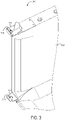
- FIG. 3 depicts the exemplary bracket system 300, according to one aspect of the present invention.
- the bracket system 300 includes one or more brackets 302, where each bracket 302 is securely installed onto a corner of the frame 102.
- the brackets 302 may be installed at each corner of the frame 102 and/or at both the inlet and outlet sides of the frame 102.
- each bracket 302 is designed to receive a pole or similar support structure that may be attached to the brackets 302.
- the brackets 302 include pole sockets 304, where a pole may be inserted through the top bracket, lowered downward and inserted through the pole socket in the bottom bracket, thereby securing the pole to the brackets 302.
- the hydro-transition unit 200 may be secured to the brackets 302 via a pole, or a similar tool, and may be unsecured by lifting the pole upwards through the brackets 302 and bracket sockets 304.
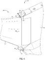
- FIG. 4 depicts the exemplary bracket system 300 with hydro-transition unit 200 secured therein, according to one aspect of the present invention.
- the present embodiment includes a pole 402 for securely attaching the hydro-transition unit 200 to the bracket system 300.
- the body 202 includes a sleeve 404 for accepting the pole 402.
- the sleeve 404 may be a cylindrical loop or sheath of the same material as the body 202 (or a different material), where a portion of the body is folded backwards and attached to itself (e.g., via stitching, adhesives, applied heat, etc.).
- the sleeve 404 includes a diameter approximately equal to that of the pole 402, or slightly larger, such that the pole 402 may be inserted through the sleeve 404.
- the body 202 may be attached to the pole 402 in other ways, such as via a plurality of hooks or a latch/clamp mechanism.
- the bracket system 300 may include a quick-release mechanism such that the hydro-transition unit 200 may be quickly detached from the bracket system 300 as a failsafe measure (to be used in emergency scenarios, such as flooding).
- the cable 204 may be attached to the pole 402 independently from the body 202.
- the cable 204 may be attached to the pole 402 via a clamp or the like, and the body 202 may be threaded onto the cable 204 (similar to a rod and curtain).
- the cable 204 allows for the body 202 to remain taught when working to transition the direction of water flow into the inlet of the frame 102.
- the cable 204 may be any suitable cable constructed of any material suitable for creating tension along the bottom of the hydro-transition unit 200 (e.g. substantially along a wall of a waterway).
- the cable 204 is constructed of a metal, such as galvanized carbon steel, carbon steel, stainless steel, etc., PVC, nylon, Teflon, or another suitable material.
- the cable 204 may be connected to the transition body 202 in any suitable way.
- the cable 204 is embedded within the material of the body 202.
- the cable 204 is connected along an edge of the transition body 202 via loops, hooks, etc.
- multiple cables 204 may be used for a single hydro-transition unit 200.
- the system may include a cable 204 along both the top and bottom of the body 200.
- the number of cables 204 may depend on the shape and application of the hydro-transition unit 200.
- a rectangular transition (with multiple anchors) may include two or more cables 204 for a single transition unit 200.
- the system may not include any cables 204 in the transition body 202.
- FIG. 5 the exemplary anchor system 500 is depicted, according to one aspect of the present invention.
- the anchor system 500 includes an end piece 502, an anchor cable 504, and an anchor 506.
- the end piece 502 may accept the body 202, the cable 204, and the anchor cable 504, and securely attach each component at a singular/central location (via a clamp or the like).
- the end piece 502 is located near the top or outer limit of the waterway 104, which may allow for the end piece 502 to avoid contact with water from the waterway 104 and also to allow the body 202 to cover a maximum area in the waterway 104.
- the system may be designed to allow for at least some water to travel around, under, or through the body 202.
- the end piece 502 may take any suitable form or shape and may be constructed of plastic, metal, or other suitable material.
- the anchor cable 504 may be attached to the anchor 506 at an anchor joint 508.
- the anchor joint 508, in some embodiments, may include a pin and lock mechanism for securing the anchor 506 to the anchor cable 504, or the anchor 506 and anchor cable 504 may be permanently secured at the anchor joint 508 via welding or another appropriate process.
- the anchor 506, anchor joint 508, and anchor cable 504 may be a unitary piece that is manufactured as a single unit.
- the anchor 506, anchor joint 508, anchor cable 504, and end piece 502 may be manufactured of various materials, such as steel, iron, galvanized steel, or other metals and alloys.
- the anchor 506 is installed in close proximity to the frame 102 (not shown) for providing resistive force to the body 202 of the hydro-transition unit 200.
- the anchor 506 may be installed in the ground near (or in) the waterway 104 (e.g., in the embankment).
- the anchor 506 may be driven downwards into the ground, or in some embodiments the ground may be excavated for creating a hole for receiving the anchor, where the hole may be recovered or filled with cement (or another appropriate filling material).
- the systems discussed herein may be used in a variety of environments.
- the body 202 and/or cable 204 of the transition unit 200 are anchored to an object other than the ground (such as, for example, a tree in situations where the system 100 is installed in a river).
- the anchor 506 may take the form of a cable (e.g., to be wrapped around a tree or other object), a clasp (e.g., to be attached to another object), a hook, etc.
- FIG. 6 depicts an alternate embodiment of the hydro-transitions system 100, according to one aspect of the present invention.
- the hydro-transition units 200 may include a body 602, where the body 602 covers a space between the waterway 104 wall and the hydro-transition unit 200.
- the body 602 is a unitary component, and is manufactured as a single fabric or reinforced material.
- portions of the body 602 may be manufactured separately and be joined around or near components of the hydro-transition unit 200 (e.g., the cable, bracket system, anchor system).
- the body 602 is a unitary piece with the rest of the hydro-transition unit 200 and is inflatable or the like (e.g., to prevent water from passing between the upstream and downstream portions of the hydro-transition unit).
- FIG. 7 another alternate embodiment of the hydro-transitions system 100 is depicted, according to one embodiment of the present invention.
- an anchor system such as the anchor system 500 (not shown) described herein.
- an alternative anchor system may be used, where the alternative anchor system includes a jamming anchor/compression member 702.
- the jamming anchor 702 may be a rod or pole that is securely attached to, or positioned within, the bracket system 300, and furthermore rested on or around the waterway 104 (similar to where an anchor 506 (not shown in FIG. 7 ) would be positioned).
- the jamming anchor 702 may be operable to withstand compressive loads, such as the force exerted onto the body 202 (or 602) from the water in the waterway 104, and furthermore this force may maintain the jamming anchor 702 in place (e.g., water may press against the body 202 or jamming anchor 702 and press the jamming anchor 702 into a wall of a waterway 104).
- compressive loads such as the force exerted onto the body 202 (or 602) from the water in the waterway 104, and furthermore this force may maintain the jamming anchor 702 in place (e.g., water may press against the body 202 or jamming anchor 702 and press the jamming anchor 702 into a wall of a waterway 104).
- each corner of the frame 102, or each bracket 302 of the bracket system 300 may accept a jamming anchor 702 for supporting the corners of the frame 102.
- the jamming anchor(s) 702 may act as a brace effectively securing the frame 102 in its position when opposing ends of the jamming anchors 702 are in contact with the surrounding area.
- the jamming anchor 702 may be manufactured from steel or other metals and alloys; however, in particular embodiments, the jamming anchor 702 may be manufactured from wood or other organic materials.
- the system may include additional features that assist with the acceleration of fluid through the frame 102, such as, for example, grooves, ridges, etc., on the body 202 (or 602). Additionally, in some alternate embodiments, the body 202 (or 602) may be curved, may form another shape, or may partially lay on the waterway 104 surface to aid in fluid acceleration.
Landscapes
- Engineering & Computer Science (AREA)
- Chemical & Material Sciences (AREA)
- Combustion & Propulsion (AREA)
- Mechanical Engineering (AREA)
- General Engineering & Computer Science (AREA)
- Power Engineering (AREA)
- Other Liquid Machine Or Engine Such As Wave Power Use (AREA)
- Hydraulic Turbines (AREA)
- Electrical Discharge Machining, Electrochemical Machining, And Combined Machining (AREA)
Description
- This application claims the benefit of, and priority to,
U.S. Provisional Patent App. No. 62/559,258, filed on September 15, 2017 - Generally, conventional hydro-electric power systems installed in waterways are not designed for optimal power generation. Typically, these hydro-electric power systems are installed into a waterway and only interact with the water that happens (by chance) to pass through the systems. Accordingly, these conventional systems allow for water to either pass through the systems at its natural rate, or escape the hydro-electric power converters by traveling around the system (rather than through). Therefore, there exists a long-felt but unresolved need for systems and methods for improved hydro-electric power generation. In patent document
WO2014/122731 a power generation system is provided equipped with floating bodies which are capable of floating on a water surface. The floating bodies are provided with an interval therebetween in the horizontal direction. Connecting parts connect the floating bodies to each other. A propeller is provided between the floating bodies and beneath the water surface, and is for transmitting the energy of the flowing water to a power generation unit through the rotation of the propeller by the energy of the flowing water. The power generation unit is driven by the energy of the flowing water transmitted by the propeller (50), thereby generating power. - The present disclosure relates generally to systems and methods for transitioning the speed and direction of a fluid (e.g., water) in a waterway (e.g., a shallow flow waterway, opposed to a dam system or the like) such that the fluid is directed into and accelerated through a hydro-electric power generation system. It is generally known that fluids naturally follow a path of least resistance. Accordingly, the system described herein (referred to throughout as a "hydro-transition system") manipulates the path of a fluid such that the fluid is directed through a particular passage. In various embodiments, the systems and methods for manipulating these fluids may result in accelerating the speed of the fluid, which in turn results in increased power generation. According to various aspects of the present disclosure, the systems described herein include a frame or structure installed into a waterway, and one or more hydro-transition systems attached thereto for directing the water from the waterway through the frame, rather than around the frame. These hydro-transition systems also may be further secured to the surrounding area (via an anchor or support beams) for allowing the hydro-transition system to withstand substantial force from a moving body of water. Aspects of the present disclosure provide various improvements over preexisting technology, such as: 1) increasing the volume of fluid passing through a hydro-electric power generation system; 2) increasing the power generation output via increased fluid speeds; and 3) improved failsafe mechanisms for flood management and other scenarios.
- The invention is defined in the appended independent claims. Optional features are set out in the dependent claims.
- The aspects, features, and benefits of the claimed embodiment(s) will become apparent from the following detailed written description of the embodiments and aspects taken in conjunction with the following drawings, although variations and modifications thereto may be effected.
- Further features and benefits of the present invention will be apparent from a detailed description of various embodiments thereof taken in conjunction with the following drawings, wherein similar elements are referred to with similar reference numbers, and wherein:
-
FIG. 1 shows an exemplary hydro-transitions system, according to one aspect of the present invention; -
FIG. 2 shows an exemplary hydro-transition, according to one aspect of the present invention; -
FIG. 3 shows an exemplary frame bracket, according to one aspect of the present invention; -
FIG. 4 shows an exemplary frame bracket with attached hydro-transition, according to one aspect of the present invention; -
FIG. 5 shows an exemplary hydro-transition anchor, according to one aspect of the present invention; -
FIG. 6 shows an exemplary hydro-transition system, according to one aspect of the present invention; and -
FIG. 7 shows an exemplary hydro-transition system, according to one aspect of the present invention. - The above and further features of the disclosed exemplary systems and methods will be recognized from the following detailed descriptions and drawings of particular embodiments. In various embodiments, the present systems and methods relate generally to systems and methods for transitioning the speed and direction of a fluid (e.g., water) in a waterway (or the like) such that the fluid is directed into and accelerated through a hydro-electric power generation system. It is generally known that fluids naturally follow a path of least resistance. Accordingly, the system described herein (referred to throughout as a "hydro-transition") manipulates the path of a fluid such that the fluid is directed through a particular passage. In various embodiments, the systems and methods for manipulating these fluids may result in accelerating the speed of the fluid, which in turn results in increased power generation. According to various aspects of the present disclosure, the systems described herein include a frame or structure installed into a waterway and one or more hydro-transition systems attached thereto for directing the water from the waterway through the frame, rather than around the frame. These hydro-transition systems also may be further secured to the surrounding area (via an anchor or support beams) for allowing the hydro-transition system to withstand substantial force from a moving body of water. Aspects of the present disclosure provide various improvements over preexisting technology, such as: 1) increasing the volume of fluid passing through a hydro-electric power generation system; 2) increasing the power generation output via increased fluid speeds; and 3) improved failsafe mechanisms for flood management and other scenarios.
- Referring now to the drawings,
FIG. 1 depicts an exemplary hydro-transitions system 100, according to one aspect of the present invention. - As discussed above, the exemplary hydro-
transitions system 100 may include a hydro-electric power generation structure that optimizes the power generation potential of hydrokinetic fluid turbines, or the like, in a waterway, channel, canal, stream, river, etc. In a particular embodiment, the hydro-transitions system 100 includes at least aframe 102 or similar structure in awaterway 104 or similar channel. According to various aspects of the present disclosure, theframe 102 is installed within thewaterway 104 to span approximately the entire width of thewaterway 104, such that any water flowing through thewaterway 104 may pass through theframe 102. However, in some embodiments, theframe 102 may not span approximately the entire width of thewaterway 104, ormultiple frames 102 may be adjacently installed within thewaterway 104 and the combined widths of theframes 102 may not span the entire width of thewaterway 104. In embodiments, theexemplary system 100 includes one or more hydro-transition units 200 (e.g., 1, 2, 3, 4, or more transition units). According to a particular embodiment, the hydro-transition units 200 include a body of reinforced fabric or material designed and manufactured to maintain its structural integrity when introduced to substantial force, such as a moving body of water. As will be described in greater detail herein, the one or more hydro-transition units 200 may be securely attached theframe 102, and in some embodiments attached to an opposing structure for support (e.g., via an anchor or the like). - As shown in the present embodiment, the hydro-
transition units 200 may be substantially triangular-shaped, although it should be understood that the hydro-transition units 200 may take any appropriate shape. In particular embodiments, the hydro-transition units 200 are manufactured to include a shape that allows for maximum interaction with the water in thewaterway 104. In one embodiment, the hydro-transition units 200 are installed in such a way (e.g., at a downward and/or inwardly pointing angle/orientation) that theunits 200 push water inward and in a focused direction towards the inlet of theframe 102, effectively narrowing the width of the water flow and increasing the flow rate. In this way, and in particular embodiments, turbines or other hydro-electric power generators located within theframe 102 may receive an enhanced power source/supply (e.g., the water), and may thus generate more power. - Turning now to
FIG. 2 , a hydro-transition unit 200 is shown, according to one embodiment. In embodiments, the hydro-transition unit 200 includes components such as abody 202, a cable 204 (or guy-wire), a connection at abracket system 300, and ananchor system 500. As discussed above in association withFIG. 1 , and depicted in the present embodiment, thebody 202 of the hydro-transition unit 200 includes a substantially triangular shape. According to various aspects of the present disclosure, the triangular shape of thebody 202 may conform to the wall of thewaterway 104, such that any water flowing along the wall of thewaterway 104 is "funneled" towards and into the inlet of theframe 102. - In a particular embodiment, the hydro-
transitions system 100 discussed herein may include hydro-transition units 200 only at the inlet of theframe 102; however, including hydro-transition units 200 at the outlet of theframe 102 may provide more efficient power generation. According to various aspects of the present disclosure, including hydro-transition units 200 at the outlet of theframe 102 may allow for water to smoothly exit the outlet of theframe 102, thus allowing new water to freely enter and pass through theframe 102. In some embodiments without hydro-transition units 200 at the outlet of theframe 102, water may abruptly exit theframe 102, potentially creating a low pressure pocket at the sides of the frame, and potentially creating a turbulent vortex scenario that may impeded the flow of water through the frame 102 (thus resulting in lower power generation). Therefore, including the hydro-transition units 200 at both the inlet and outlet of theframe 102 may promote laminar flow of the water and result in optimized hydro-electric power generation. - Continuing with
FIG. 2 , thebody 202 of the hydro-transition unit 200 may be supported at theframe 102 by abracket system 300, and also at the opposite end via ananchor system 500. As will be discussed in greater detail herein (e.g., during the discussion ofFIGS. 3 and5 ), the hydro-transition unit 200 withstands such substantial force from the water moving within thewaterway 104 that multiple points of support allow for thebody 202 to best move/transition water into theframe 102 inlet. According to various aspects of the present disclosure, opposite ends of thecable 204 may be attached to either thebracket system 300 or theanchor system 500, and stretched to a particular tension for providing structural support to thebody 202. For example, without thecable 204 supporting thebody 202, thebody 202 may wave or fold under strong water currents (similar to a flag waving when expose to high winds), or thebody 202 may begin to fray or erode along thebody 202 fringe. In various embodiments, thecable 204 keeps thebody 202 taught and thus allows for the most efficient redirection of the water flow into theframe 102 inlet. - In particular embodiments, the
body 202 may be constructed in a shape that is suitable to fit a channel, or the like. In some embodiments, the shape of thebody 202 is dependent upon the shape of the channel in which the hydro-transition unit 200 is to be installed. In various embodiments, thebody 202 may be substantially triangular, substantially parallelepiped (e.g., with multiple cables and anchors), rectangular, etc. In various embodiments, thebody 202 may be constructed of any suitable material that may help direct water flow. In particular embodiments, thebody 202 is constructed of a fabric, plastic, or a combination of fabric and plastic. In further embodiments, thebody 202 may be constructed of light-weight metals, polymers, ceramics, and/or composite materials. Depending on the type of fluid to be controlled, the material of thebody 202 may be rust or corrosion resistant. A hydro-transitions system, such as the one described in regards to the example above, may result in an increase of power generation efficiency of a turbine system of about 1%-10%, 10%-20%, 20%-30%, or 40%-70% due to the increased volume and current flow of the water. -
FIG. 3 depicts theexemplary bracket system 300, according to one aspect of the present invention. - In embodiments, the
bracket system 300 includes one ormore brackets 302, where eachbracket 302 is securely installed onto a corner of theframe 102. According to various embodiments, thebrackets 302 may be installed at each corner of theframe 102 and/or at both the inlet and outlet sides of theframe 102. - In embodiments, each
bracket 302 is designed to receive a pole or similar support structure that may be attached to thebrackets 302. As shown in the present embodiment, thebrackets 302 includepole sockets 304, where a pole may be inserted through the top bracket, lowered downward and inserted through the pole socket in the bottom bracket, thereby securing the pole to thebrackets 302. As will be discussed in greater detail herein, the hydro-transition unit 200 may be secured to thebrackets 302 via a pole, or a similar tool, and may be unsecured by lifting the pole upwards through thebrackets 302 andbracket sockets 304. -
FIG. 4 depicts theexemplary bracket system 300 with hydro-transition unit 200 secured therein, according to one aspect of the present invention. As mentioned above in association with the discussion ofFIG. 3 , the present embodiment includes apole 402 for securely attaching the hydro-transition unit 200 to thebracket system 300. In the present embodiment, thebody 202 includes asleeve 404 for accepting thepole 402. According to various aspects of the present disclosure, thesleeve 404 may be a cylindrical loop or sheath of the same material as the body 202 (or a different material), where a portion of the body is folded backwards and attached to itself (e.g., via stitching, adhesives, applied heat, etc.). In certain embodiments, thesleeve 404 includes a diameter approximately equal to that of thepole 402, or slightly larger, such that thepole 402 may be inserted through thesleeve 404. In various embodiments, thebody 202 may be attached to thepole 402 in other ways, such as via a plurality of hooks or a latch/clamp mechanism. In some embodiments, thebracket system 300 may include a quick-release mechanism such that the hydro-transition unit 200 may be quickly detached from thebracket system 300 as a failsafe measure (to be used in emergency scenarios, such as flooding). - According to various aspects of the present disclosure, the
cable 204 may be attached to thepole 402 independently from thebody 202. For example, thecable 204 may be attached to thepole 402 via a clamp or the like, and thebody 202 may be threaded onto the cable 204 (similar to a rod and curtain). As discussed briefly above, thecable 204 allows for thebody 202 to remain taught when working to transition the direction of water flow into the inlet of theframe 102. - In particular embodiments, the
cable 204 may be any suitable cable constructed of any material suitable for creating tension along the bottom of the hydro-transition unit 200 (e.g. substantially along a wall of a waterway). In one embodiment, thecable 204 is constructed of a metal, such as galvanized carbon steel, carbon steel, stainless steel, etc., PVC, nylon, Teflon, or another suitable material. - In certain embodiments, the
cable 204 may be connected to thetransition body 202 in any suitable way. In various embodiments, thecable 204 is embedded within the material of thebody 202. In some embodiments, thecable 204 is connected along an edge of thetransition body 202 via loops, hooks, etc. - As will be understood,
multiple cables 204 may be used for a single hydro-transition unit 200. In various embodiments, the system may include acable 204 along both the top and bottom of thebody 200. In some embodiments, the number ofcables 204 may depend on the shape and application of the hydro-transition unit 200. In these embodiments, for example, a rectangular transition (with multiple anchors) may include two ormore cables 204 for asingle transition unit 200. In further embodiments, the system may not include anycables 204 in thetransition body 202. - Turning now to
FIG. 5 , theexemplary anchor system 500 is depicted, according to one aspect of the present invention. - In various embodiments, the
anchor system 500 includes anend piece 502, ananchor cable 504, and ananchor 506. In particular embodiments, theend piece 502 may accept thebody 202, thecable 204, and theanchor cable 504, and securely attach each component at a singular/central location (via a clamp or the like). Generally, theend piece 502 is located near the top or outer limit of thewaterway 104, which may allow for theend piece 502 to avoid contact with water from thewaterway 104 and also to allow thebody 202 to cover a maximum area in thewaterway 104. For example, if theend piece 502 were located at a position near the middle of thewaterway 104, water would escape thebody 202 by traveling in the uncaptured space between thebody 202 and waterway wall. However, in some embodiments, the system may be designed to allow for at least some water to travel around, under, or through thebody 202. In various embodiments, theend piece 502 may take any suitable form or shape and may be constructed of plastic, metal, or other suitable material. - In certain embodiments, the
anchor cable 504 may be attached to theanchor 506 at an anchor joint 508. The anchor joint 508, in some embodiments, may include a pin and lock mechanism for securing theanchor 506 to theanchor cable 504, or theanchor 506 andanchor cable 504 may be permanently secured at the anchor joint 508 via welding or another appropriate process. In other embodiments, theanchor 506, anchor joint 508, andanchor cable 504 may be a unitary piece that is manufactured as a single unit. According to various aspects of the present disclosure, theanchor 506, anchor joint 508,anchor cable 504, andend piece 502 may be manufactured of various materials, such as steel, iron, galvanized steel, or other metals and alloys. - Continuing with
FIG, 5 , theanchor 506 is installed in close proximity to the frame 102 (not shown) for providing resistive force to thebody 202 of the hydro-transition unit 200. In particular embodiments, theanchor 506 may be installed in the ground near (or in) the waterway 104 (e.g., in the embankment). For example, theanchor 506 may be driven downwards into the ground, or in some embodiments the ground may be excavated for creating a hole for receiving the anchor, where the hole may be recovered or filled with cement (or another appropriate filling material). - According to various aspects of the present disclosure, the systems discussed herein may be used in a variety of environments. In some situations, the
body 202 and/orcable 204 of thetransition unit 200 are anchored to an object other than the ground (such as, for example, a tree in situations where thesystem 100 is installed in a river). In these embodiments, and others, theanchor 506 may take the form of a cable (e.g., to be wrapped around a tree or other object), a clasp (e.g., to be attached to another object), a hook, etc. -
FIG. 6 depicts an alternate embodiment of the hydro-transitions system 100, according to one aspect of the present invention. - In some scenarios, based on the
waterway 104 shape, it may be beneficial to cover any space between thewaterway 104 walls and the bodies of the hydro-transition units 200 (e.g., to prevent water from overflowing into the space, to prevent rubbish from collecting in the space, to prevent wildlife from becoming trapped in the space, etc.) Accordingly, and in various embodiments, the hydro-transition units 200 may include abody 602, where thebody 602 covers a space between thewaterway 104 wall and the hydro-transition unit 200. In the present embodiment, thebody 602 is a unitary component, and is manufactured as a single fabric or reinforced material. In some embodiments, portions of thebody 602 may be manufactured separately and be joined around or near components of the hydro-transition unit 200 (e.g., the cable, bracket system, anchor system). In further embodiments, thebody 602 is a unitary piece with the rest of the hydro-transition unit 200 and is inflatable or the like (e.g., to prevent water from passing between the upstream and downstream portions of the hydro-transition unit). - Turning now to
FIG. 7 , another alternate embodiment of the hydro-transitions system 100 is depicted, according to one embodiment of the present invention. - In some scenarios, for example during winter months in a cold climate, the ground near a
water channel 104 may be particularly difficult to excavate, notwithstanding help from machinery. In these scenarios, it may be difficult to install an anchor system, such as the anchor system 500 (not shown) described herein. Accordingly, and as shown in the present embodiment, an alternative anchor system may be used, where the alternative anchor system includes a jamming anchor/compression member 702. In particular embodiments, the jamminganchor 702 may be a rod or pole that is securely attached to, or positioned within, thebracket system 300, and furthermore rested on or around the waterway 104 (similar to where an anchor 506 (not shown inFIG. 7 ) would be positioned). In certain embodiments, the jamminganchor 702 may be operable to withstand compressive loads, such as the force exerted onto the body 202 (or 602) from the water in thewaterway 104, and furthermore this force may maintain the jamminganchor 702 in place (e.g., water may press against thebody 202 or jamminganchor 702 and press the jamminganchor 702 into a wall of a waterway 104). - According to various aspects of the present disclosure, each corner of the
frame 102, or eachbracket 302 of thebracket system 300, may accept ajamming anchor 702 for supporting the corners of theframe 102. As such, and in various embodiments, the jamming anchor(s) 702 may act as a brace effectively securing theframe 102 in its position when opposing ends of the jamming anchors 702 are in contact with the surrounding area. In some embodiment, the jamminganchor 702 may be manufactured from steel or other metals and alloys; however, in particular embodiments, the jamminganchor 702 may be manufactured from wood or other organic materials. - In other alternate embodiments, the system may include additional features that assist with the acceleration of fluid through the
frame 102, such as, for example, grooves, ridges, etc., on the body 202 (or 602). Additionally, in some alternate embodiments, the body 202 (or 602) may be curved, may form another shape, or may partially lay on thewaterway 104 surface to aid in fluid acceleration. - Aspects, features, and benefits of the claimed invention(s) will become apparent from the information disclosed in the exhibits.
- It will, nevertheless, be understood that no limitation of the scope of the disclosure is intended by the information disclosed in the exhibits ; any alterations and further modifications of the described or illustrated embodiments, and any further applications of the principles of the disclosure as illustrated therein are contemplated as would normally occur to one skilled in the art to which the disclosure relates.
- The foregoing description of the exemplary embodiments has been presented only for the purposes of illustration and description and is not intended to be exhaustive or to limit the inventions to the precise forms disclosed. Many modifications and variations are possible in light of the above teaching.
- The embodiments were chosen and described in order to explain the principles of the inventions and their practical application so as to enable others skilled in the art to utilize the inventions and various embodiments and with various modifications as are suited to the particular use contemplated. Alternative embodiments will become apparent to those skilled in the art to which the present inventions pertain. Accordingly, the scope of the present inventions is defined by the appended claims rather than the foregoing description and the exemplary embodiments described therein.
Claims (7)
- A hydrokinetic turbine system (100) comprising:a frame (102) for positioning the turbine system in a waterway (104);one or more turbines operatively connected to the frame;at least one bracket (302) coupled to the frame; anda transition (200) operatively connected to the at least one bracket, the transition comprising:a substantially flat body (202) for spanning a distance between the frame and a portion of the waterway;a cable (204) operatively connected to an edge of the substantially flat body, the cable for providing tension in the substantially flat body; andan anchor system (500) for anchoring the substantially flat body within the waterway, wherein:the hydrokinetic turbine system is for harvesting hydrokinetic energy in a waterway;the frame comprises one or more side walls;the at least one bracket is coupled to the frame by coupling to a corner of the one or more side walls, wherein the at least one bracket includes a mechanism (304) for securely receiving a pole (402); andthe substantially flat body is a reinforced fabric-based material for spanning a distance between the frame and a portion of the waterway.
- The system of claim 1, wherein the cable is connected to the frame and to an end piece (502);the end piece operatively connected to the substantially flat body, the cable, and the anchor system; andthe anchor system is an anchor for connecting the substantially flat body to a stationary object.
- The system of claim 2, further comprising a rod operatively connected to an end of the transition and the at least one bracket.
- The system of claim 2, wherein the at least one bracket comprises a first bracket and second bracket, and wherein:the substantially flat body is substantially triangular in shape and is comprised of a fabric material for directing water through the turbine system;a first point of the substantially flat triangular-shaped body is connected to the first bracket;a second point of the substantially flat triangular-shaped body is connected to the second bracket; anda third point of the substantially flat triangular-shaped body is connected to the end piece.
- A method for harvesting hydrokinetic energy in a waterway (104) comprising:receiving hydrokinetic energy from rotation of at least one turbine within a frame (102), wherein the at least one turbine is rotated by a flow of shallow water and wherein the flow of shallow water is at least partially directed through the frame via a transition operatively connected to at least one bracket (302) coupled to the frame and secured in a position to direct water through the frame within the waterway, wherein the transition comprises:a substantially flat body (202) for spanning a distance between the frame and a portion of the waterway;a cable (204) operatively connected to an edge of the substantially flat body, the cable for providing tension in the substantially flat body; andan anchor system (500) for anchoring the substantially flat body within the waterway;wherein:the frame, the at least one bracket and the transition are comprised in a hydrokinetic turbine system for harvesting hydrokinetic energy in a waterway;the frame comprises one or more side walls;the at least one bracket is coupled to the frame by coupling to a corner of the one or more side walls, wherein the at least one bracket includes a mechanism (304) for securely receiving a pole (402); andthe substantially flat body is a reinforced fabric-based material for spanning a distance between the frame and a portion of the waterway.
- The system of claim 1, wherein the anchor system comprises a jamming anchor (702) extending along a length of the substantially flat body for pressing against at least a portion of an embankment of the waterway.
- The system of claim 3, wherein the at least one bracket comprises a first bracket and a second bracket; wherein:the rod operatively connected to the substantially flat body; andthe rod is operatively connected to the first bracket and the second bracket.
Applications Claiming Priority (2)
| Application Number | Priority Date | Filing Date | Title |
|---|---|---|---|
| US201762559258P | 2017-09-15 | 2017-09-15 | |
| PCT/US2018/051371 WO2019055934A1 (en) | 2017-09-15 | 2018-09-17 | Hydro transition systems and methods of using the same |
Publications (3)
| Publication Number | Publication Date |
|---|---|
| EP3682107A1 EP3682107A1 (en) | 2020-07-22 |
| EP3682107A4 EP3682107A4 (en) | 2021-03-24 |
| EP3682107B1 true EP3682107B1 (en) | 2022-12-28 |
Family
ID=65720061
Family Applications (1)
| Application Number | Title | Priority Date | Filing Date |
|---|---|---|---|
| EP18855328.3A Active EP3682107B1 (en) | 2017-09-15 | 2018-09-17 | Hydro transition systems and methods of using the same |
Country Status (5)
| Country | Link |
|---|---|
| US (2) | US10724497B2 (en) |
| EP (1) | EP3682107B1 (en) |
| ES (1) | ES2940320T3 (en) |
| MX (2) | MX2020002902A (en) |
| WO (1) | WO2019055934A1 (en) |
Families Citing this family (4)
| Publication number | Priority date | Publication date | Assignee | Title |
|---|---|---|---|---|
| CN111424606B (en) * | 2020-04-01 | 2021-12-07 | 辰源海洋科技(广东)有限公司 | Ecological seawall structure for ocean ecological restoration |
| CN113216072B (en) * | 2021-04-19 | 2022-06-14 | 中国电建集团华东勘测设计研究院有限公司 | Super-large-flow bank slope type water inlet arrangement structure for space partition layered drainage |
| WO2024236492A1 (en) * | 2023-05-15 | 2024-11-21 | Maclec Technical Project Laboratory Private Limited | System and method for generating elctrical energy by converting hydrokinetic energy in aquatic environments |
| US12385504B2 (en) * | 2023-06-12 | 2025-08-12 | Jiangsu University | Floating counter-rotating vortex-eliminating device for pump station, and pump station |
Family Cites Families (65)
| Publication number | Priority date | Publication date | Assignee | Title |
|---|---|---|---|---|
| US3807890A (en) * | 1972-10-12 | 1974-04-30 | O Wright | Water power apparatus |
| JPH09256941A (en) * | 1996-03-25 | 1997-09-30 | Osamu Inoue | Curved water-turbine-blade type hydraulic power generation mechanism |
| US6109863A (en) | 1998-11-16 | 2000-08-29 | Milliken; Larry D. | Submersible appartus for generating electricity and associated method |
| US6320273B1 (en) | 2000-02-12 | 2001-11-20 | Otilio Nemec | Large vertical-axis variable-pitch wind turbine |
| JP4363799B2 (en) | 2001-06-08 | 2009-11-11 | 株式会社東芝 | Turbine assembly transport stand, turbine assembly method using the stand, and transport method |
| CN1350357A (en) | 2001-09-08 | 2002-05-22 | 贺雷 | Ring motor |
| RU2216662C1 (en) | 2002-09-30 | 2003-11-20 | Открытое акционерное общество "Петербургский трамвайно-механический завод" | Magnetic clutch |
| TW200519292A (en) | 2003-10-13 | 2005-06-16 | Isidro Umali Ursua | Turbine housing and floatation assembly |
| GB2408778A (en) | 2003-12-04 | 2005-06-08 | Calum Mackinnon | Current stream energy device |
| WO2006133703A1 (en) | 2005-06-13 | 2006-12-21 | Aalborg Universitet | Magnetic device for transfer of forces |
| US8664784B2 (en) | 2005-09-12 | 2014-03-04 | Gulfstream Technologies, Inc. | Louvered turbine for generating electric power from a water current |
| US7456514B2 (en) | 2005-09-22 | 2008-11-25 | Verdant Power | Kinetic hydropower generation from slow-moving water flows |
| GB0608091D0 (en) * | 2006-04-25 | 2006-05-31 | Kelvin Steven B | Floating power generation plant |
| JP5155574B2 (en) | 2006-04-25 | 2013-03-06 | 赤 嶺 辰 実 | Rotating blade for wind power generation using inertial force, wind power generation apparatus using the same, and wind power generation system |
| US20080018115A1 (en) | 2006-07-20 | 2008-01-24 | Boray Technologies, Inc. | Semi-submersible hydroelectric power plant |
| WO2008045662A2 (en) | 2006-10-10 | 2008-04-17 | Adaptide, Inc. | Adaptive tidal current power extraction device |
| GB0703827D0 (en) | 2007-02-28 | 2007-04-11 | Rolls Royce Plc | Rotor seal segment |
| US7944075B2 (en) | 2007-03-07 | 2011-05-17 | Daniel Boone | Wind turbine based energy storage system and method using heavy weighted devices |
| JP4022244B2 (en) * | 2007-04-06 | 2007-12-12 | シーベルインターナショナル株式会社 | Hydroelectric generator |
| WO2008131519A1 (en) | 2007-04-27 | 2008-11-06 | Glenn Raymond Lux | Modified darrieus vertical axis turbine |
| GB0713931D0 (en) | 2007-07-17 | 2007-08-29 | Nexgen Group Ltd | Vertical axis wind turbine |
| US8102071B2 (en) | 2007-10-18 | 2012-01-24 | Catlin Christopher S | River and tidal power harvester |
| US8393853B2 (en) | 2007-11-19 | 2013-03-12 | Ocean Renewable Power Company, Llc | High efficiency turbine and method of generating power |
| KR100929495B1 (en) | 2007-11-23 | 2009-12-03 | 한국해양연구원 | Prefab Helical Turbine |
| GB2457682B (en) | 2008-02-21 | 2012-03-28 | Magnomatics Ltd | Variable magnetic gears |
| WO2009155467A2 (en) | 2008-06-18 | 2009-12-23 | Duffey Christopher K | Variable speed synchronous generator |
| GB2461265A (en) | 2008-06-23 | 2009-12-30 | Tidal Energy Ltd | Tidal turbine with limited axial thrust |
| US20100032952A1 (en) | 2008-08-08 | 2010-02-11 | Hatch Gareth P | Turbine generator having direct magnetic gear drive |
| US8616829B2 (en) | 2008-11-13 | 2013-12-31 | Concepts Eti, Inc. | Shrouded turbine assembly |
| US7959411B2 (en) | 2009-04-07 | 2011-06-14 | Northwest Pipe Company | In-pipe hydro-electric power system and turbine |
| US8487470B2 (en) | 2009-05-22 | 2013-07-16 | Derek Grassman | Vertical axis wind turbine and generator therefore |
| GB0920148D0 (en) | 2009-11-17 | 2009-12-30 | Magnomatics Ltd | Magnetically geared machine for marine generation |
| DE202010001796U1 (en) * | 2010-02-04 | 2010-06-10 | Stein Ht Gmbh Spezialtiefbau | Hydropower plant |
| GB2477533B (en) | 2010-02-05 | 2012-05-30 | Rolls Royce Plc | A bidirectional water turbine |
| AU2010346297A1 (en) * | 2010-02-22 | 2012-09-06 | Hidra Force D.O.O | Driving engine (water turbine) of hydrokinetic floating power plant with enhanced efficiency degree, and hydrokinetic floating power plant module |
| US9103084B2 (en) * | 2010-04-23 | 2015-08-11 | French Development Enterprises, LLC | Intelligent hydroelectric dam with power storage |
| WO2011160210A2 (en) | 2010-06-21 | 2011-12-29 | Mavi Innovations Inc. | Duct assembly for a cross-flow water turbine |
| US9476401B2 (en) * | 2010-07-20 | 2016-10-25 | Differential Dynamics Corporation | Marine hydrokinetic turbine |
| US8916987B2 (en) * | 2010-09-14 | 2014-12-23 | Wingmill Marine Energy, Inc. | Hydrokinetic electrical generating device |
| WO2012039667A1 (en) * | 2010-09-24 | 2012-03-29 | Mohamed Sahbi Belarbi | Energy generation system including pontoon unit and water wheel |
| WO2012094336A2 (en) | 2011-01-03 | 2012-07-12 | Roter Samuel | Fluidic flow capture and acceleration apparatus for hyper-conversion |
| US9337712B2 (en) | 2011-03-04 | 2016-05-10 | Allen G. Storaasli | Eccentric magnetic gear system based on repulsion |
| US8786122B2 (en) * | 2011-07-27 | 2014-07-22 | Dlz Corporation | Horizontal-axis hydrokinetic water turbine system with water pump |
| US9086047B2 (en) | 2011-09-17 | 2015-07-21 | Karim Salehpoor | Renewable energy extraction device |
| US8840364B2 (en) | 2012-01-05 | 2014-09-23 | General Electric Company | System for aligning turbomachinery |
| FR2986280B1 (en) * | 2012-01-27 | 2016-09-16 | Converteam Tech Ltd | HYDROLIAN ROTOR COMPRISING AT LEAST ONE MOBILE BLADE ROTATING AROUND A RADIAL AXIS AND MEANS FOR LIMITING THE MOTION IN ROTATION OF SAID BLADE, AND HYDROLIENNE COMPRISING SUCH A ROTOR |
| WO2013143596A1 (en) | 2012-03-29 | 2013-10-03 | Siemens Aktiengesellschaft | Magnetic gear box arrangement |
| JP6020988B2 (en) * | 2012-04-19 | 2016-11-02 | 独立行政法人国立高等専門学校機構 | Hydroelectric generator |
| US9303619B2 (en) | 2012-11-16 | 2016-04-05 | Hydro Alternative Energy, Inc. | Hydrokinetic energy conversion system with buoyancy and ballast controls to harness underwater currents for the generation of electrical power |
| CN103001454B (en) | 2012-12-10 | 2015-05-06 | 河南理工大学 | Axial disk permanent magnetic reduction gear based on magnetization effect |
| US20140183996A1 (en) | 2012-12-29 | 2014-07-03 | Hongping He | Magnetic Powertrain and Components |
| WO2014122731A1 (en) * | 2013-02-05 | 2014-08-14 | 株式会社音力発電 | Power generation system |
| WO2014158968A1 (en) | 2013-03-14 | 2014-10-02 | National Oilwell Varco, L.P. | Magnetic cycloid gear |
| US20140265335A1 (en) | 2013-03-15 | 2014-09-18 | Bruno Peter Andreis | Ultra high efficiency power generation system and water turbine |
| US8876448B1 (en) | 2013-08-28 | 2014-11-04 | General Electric Company | Gas turbine half-casing shipping fixture |
| US9618002B1 (en) | 2013-09-27 | 2017-04-11 | University Of South Florida | Mini notched turbine generator |
| GB2519531B (en) | 2013-10-23 | 2016-06-29 | Rolls Royce Plc | Method and apparatus for supporting blades |
| GB2543988B (en) | 2014-07-11 | 2020-05-27 | Instream Energy Systems Corp | Hydrokinetic turbine with configurable blades for bi-directional rotation |
| CN104393725B (en) | 2014-12-10 | 2017-06-13 | 哈尔滨工业大学 | Axial magnetic field electromagnetic planetary gear speed changer |
| KR101599708B1 (en) * | 2015-03-18 | 2016-03-04 | 이동인 | Submersible platform for generating electricity |
| WO2016200862A1 (en) * | 2015-06-08 | 2016-12-15 | Power Development Inc. | Modular hydrokinetic turbine |
| US10396687B2 (en) | 2015-08-20 | 2019-08-27 | Lawrence Livermore National Security, Llc | Stator positioner for electrostatic generator electrodes and new electrode design |
| US20170138333A1 (en) * | 2015-11-16 | 2017-05-18 | Corporacion Andina De Fomento | Modular hydrokinetic motor device and method |
| US10273818B2 (en) | 2016-04-15 | 2019-04-30 | Rolls-Royce North American Technologies Inc. | Gas turbine engine with compliant layer for turbine vane assemblies |
| FR3069229B1 (en) | 2017-07-20 | 2019-07-26 | Safran Aircraft Engines | TOOL FOR ATTACHING AN EXTERNAL VIROLE OF AN INTERMEDIATE CARTER OF A TURBOMACHINE |
-
2018
- 2018-09-17 EP EP18855328.3A patent/EP3682107B1/en active Active
- 2018-09-17 ES ES18855328T patent/ES2940320T3/en active Active
- 2018-09-17 MX MX2020002902A patent/MX2020002902A/en unknown
- 2018-09-17 WO PCT/US2018/051371 patent/WO2019055934A1/en not_active Ceased
- 2018-09-17 US US16/133,285 patent/US10724497B2/en active Active
-
2020
- 2020-03-13 MX MX2023013739A patent/MX2023013739A/en unknown
- 2020-06-11 US US16/899,182 patent/US11591998B2/en active Active
Also Published As
| Publication number | Publication date |
|---|---|
| US20210095632A1 (en) | 2021-04-01 |
| US20190085813A1 (en) | 2019-03-21 |
| ES2940320T3 (en) | 2023-05-05 |
| EP3682107A1 (en) | 2020-07-22 |
| US10724497B2 (en) | 2020-07-28 |
| WO2019055934A1 (en) | 2019-03-21 |
| EP3682107A4 (en) | 2021-03-24 |
| US11591998B2 (en) | 2023-02-28 |
| MX2023013739A (en) | 2023-11-28 |
| MX2020002902A (en) | 2020-10-01 |
Similar Documents
| Publication | Publication Date | Title |
|---|---|---|
| US11591998B2 (en) | Hydro transition systems and methods of using the same | |
| US8633609B2 (en) | Sub sea central axis turbine with rearwardly raked blades | |
| EP2304225B1 (en) | Blade for a water turbine | |
| JP4787286B2 (en) | Hydroelectric generator | |
| CA2583662A1 (en) | Two-way generation tidal power plant with one-way turbines | |
| AU759975B2 (en) | Partial splitter vane for reaction hydraulic turbine | |
| JP2009114937A (en) | Hydraulic power generation device | |
| JP2013504714A (en) | Underwater hydroelectric generator and method | |
| EP3123024B1 (en) | Hydroelectric turbine having rotor with open centre | |
| JP2013224592A (en) | Hydraulic power generating device | |
| JP4856134B2 (en) | Hydroelectric generator | |
| WO2019049901A1 (en) | Hydraulic power generation device | |
| US9909555B2 (en) | Underwater power generation apparatus | |
| CN202991326U (en) | Underwater anchoring device for water turbine | |
| JP7673080B2 (en) | Waterway equipped with a bubble screen, and bubble screen therefor | |
| RU2380478C1 (en) | Mobile dam of parachute type | |
| DE102012022858B3 (en) | Marine current power plant for obtaining electrical energy from sea, has tubular body for installation near river bank, where tubular body has venturi section, upper open end and lower open end, while turbine is placed in venturi section | |
| JPH08338354A (en) | Hydraulic turbine device for low flow velocity and water conveyance direction setting method for hydraulic turbine for low flow velocity | |
| JP4805745B2 (en) | Drifting material inflow prevention and water collecting device | |
| CA2224746A1 (en) | Power generation | |
| KR101066953B1 (en) | Hydropower Unit with Automatic Folding Spread | |
| JP7240798B1 (en) | Fluid power generation system and its installation structure | |
| JPS6210475A (en) | Wave activated power generating system | |
| US20160237981A1 (en) | Tidal current power generation structure | |
| RU2378451C2 (en) | Mobile hydropower structure of multiple use (versions) |
Legal Events
| Date | Code | Title | Description |
|---|---|---|---|
| STAA | Information on the status of an ep patent application or granted ep patent |
Free format text: STATUS: THE INTERNATIONAL PUBLICATION HAS BEEN MADE |
|
| PUAI | Public reference made under article 153(3) epc to a published international application that has entered the european phase |
Free format text: ORIGINAL CODE: 0009012 |
|
| STAA | Information on the status of an ep patent application or granted ep patent |
Free format text: STATUS: REQUEST FOR EXAMINATION WAS MADE |
|
| 17P | Request for examination filed |
Effective date: 20200407 |
|
| AK | Designated contracting states |
Kind code of ref document: A1 Designated state(s): AL AT BE BG CH CY CZ DE DK EE ES FI FR GB GR HR HU IE IS IT LI LT LU LV MC MK MT NL NO PL PT RO RS SE SI SK SM TR |
|
| AX | Request for extension of the european patent |
Extension state: BA ME |
|
| DAV | Request for validation of the european patent (deleted) | ||
| DAX | Request for extension of the european patent (deleted) | ||
| REG | Reference to a national code |
Ref country code: DE Ref legal event code: R079 Ref document number: 602018044866 Country of ref document: DE Free format text: PREVIOUS MAIN CLASS: F03B0013100000 Ipc: F03B0017060000 |
|
| A4 | Supplementary search report drawn up and despatched |
Effective date: 20210219 |
|
| RIC1 | Information provided on ipc code assigned before grant |
Ipc: E02B 3/04 20060101ALI20210215BHEP Ipc: F03B 17/06 20060101AFI20210215BHEP Ipc: E02B 9/00 20060101ALI20210215BHEP Ipc: E02B 9/04 20060101ALI20210215BHEP Ipc: E02B 9/02 20060101ALI20210215BHEP |
|
| GRAP | Despatch of communication of intention to grant a patent |
Free format text: ORIGINAL CODE: EPIDOSNIGR1 |
|
| STAA | Information on the status of an ep patent application or granted ep patent |
Free format text: STATUS: GRANT OF PATENT IS INTENDED |
|
| INTG | Intention to grant announced |
Effective date: 20220201 |
|
| GRAJ | Information related to disapproval of communication of intention to grant by the applicant or resumption of examination proceedings by the epo deleted |
Free format text: ORIGINAL CODE: EPIDOSDIGR1 |
|
| STAA | Information on the status of an ep patent application or granted ep patent |
Free format text: STATUS: REQUEST FOR EXAMINATION WAS MADE |
|
| GRAP | Despatch of communication of intention to grant a patent |
Free format text: ORIGINAL CODE: EPIDOSNIGR1 |
|
| STAA | Information on the status of an ep patent application or granted ep patent |
Free format text: STATUS: GRANT OF PATENT IS INTENDED |
|
| INTC | Intention to grant announced (deleted) | ||
| INTG | Intention to grant announced |
Effective date: 20220706 |
|
| GRAS | Grant fee paid |
Free format text: ORIGINAL CODE: EPIDOSNIGR3 |
|
| GRAA | (expected) grant |
Free format text: ORIGINAL CODE: 0009210 |
|
| STAA | Information on the status of an ep patent application or granted ep patent |
Free format text: STATUS: THE PATENT HAS BEEN GRANTED |
|
| AK | Designated contracting states |
Kind code of ref document: B1 Designated state(s): AL AT BE BG CH CY CZ DE DK EE ES FI FR GB GR HR HU IE IS IT LI LT LU LV MC MK MT NL NO PL PT RO RS SE SI SK SM TR |
|
| REG | Reference to a national code |
Ref country code: GB Ref legal event code: FG4D |
|
| REG | Reference to a national code |
Ref country code: CH Ref legal event code: EP |
|
| REG | Reference to a national code |
Ref country code: DE Ref legal event code: R096 Ref document number: 602018044866 Country of ref document: DE |
|
| REG | Reference to a national code |
Ref country code: AT Ref legal event code: REF Ref document number: 1540638 Country of ref document: AT Kind code of ref document: T Effective date: 20230115 |
|
| REG | Reference to a national code |
Ref country code: IE Ref legal event code: FG4D |
|
| REG | Reference to a national code |
Ref country code: NL Ref legal event code: FP |
|
| REG | Reference to a national code |
Ref country code: LT Ref legal event code: MG9D |
|
| PG25 | Lapsed in a contracting state [announced via postgrant information from national office to epo] |
Ref country code: SE Free format text: LAPSE BECAUSE OF FAILURE TO SUBMIT A TRANSLATION OF THE DESCRIPTION OR TO PAY THE FEE WITHIN THE PRESCRIBED TIME-LIMIT Effective date: 20221228 Ref country code: NO Free format text: LAPSE BECAUSE OF FAILURE TO SUBMIT A TRANSLATION OF THE DESCRIPTION OR TO PAY THE FEE WITHIN THE PRESCRIBED TIME-LIMIT Effective date: 20230328 Ref country code: LT Free format text: LAPSE BECAUSE OF FAILURE TO SUBMIT A TRANSLATION OF THE DESCRIPTION OR TO PAY THE FEE WITHIN THE PRESCRIBED TIME-LIMIT Effective date: 20221228 Ref country code: FI Free format text: LAPSE BECAUSE OF FAILURE TO SUBMIT A TRANSLATION OF THE DESCRIPTION OR TO PAY THE FEE WITHIN THE PRESCRIBED TIME-LIMIT Effective date: 20221228 |
|
| REG | Reference to a national code |
Ref country code: ES Ref legal event code: FG2A Ref document number: 2940320 Country of ref document: ES Kind code of ref document: T3 Effective date: 20230505 |
|
| REG | Reference to a national code |
Ref country code: AT Ref legal event code: MK05 Ref document number: 1540638 Country of ref document: AT Kind code of ref document: T Effective date: 20221228 |
|
| PG25 | Lapsed in a contracting state [announced via postgrant information from national office to epo] |
Ref country code: RS Free format text: LAPSE BECAUSE OF FAILURE TO SUBMIT A TRANSLATION OF THE DESCRIPTION OR TO PAY THE FEE WITHIN THE PRESCRIBED TIME-LIMIT Effective date: 20221228 Ref country code: LV Free format text: LAPSE BECAUSE OF FAILURE TO SUBMIT A TRANSLATION OF THE DESCRIPTION OR TO PAY THE FEE WITHIN THE PRESCRIBED TIME-LIMIT Effective date: 20221228 Ref country code: HR Free format text: LAPSE BECAUSE OF FAILURE TO SUBMIT A TRANSLATION OF THE DESCRIPTION OR TO PAY THE FEE WITHIN THE PRESCRIBED TIME-LIMIT Effective date: 20221228 Ref country code: GR Free format text: LAPSE BECAUSE OF FAILURE TO SUBMIT A TRANSLATION OF THE DESCRIPTION OR TO PAY THE FEE WITHIN THE PRESCRIBED TIME-LIMIT Effective date: 20230329 |
|
| PG25 | Lapsed in a contracting state [announced via postgrant information from national office to epo] |
Ref country code: SM Free format text: LAPSE BECAUSE OF FAILURE TO SUBMIT A TRANSLATION OF THE DESCRIPTION OR TO PAY THE FEE WITHIN THE PRESCRIBED TIME-LIMIT Effective date: 20221228 Ref country code: RO Free format text: LAPSE BECAUSE OF FAILURE TO SUBMIT A TRANSLATION OF THE DESCRIPTION OR TO PAY THE FEE WITHIN THE PRESCRIBED TIME-LIMIT Effective date: 20221228 Ref country code: PT Free format text: LAPSE BECAUSE OF FAILURE TO SUBMIT A TRANSLATION OF THE DESCRIPTION OR TO PAY THE FEE WITHIN THE PRESCRIBED TIME-LIMIT Effective date: 20230428 Ref country code: EE Free format text: LAPSE BECAUSE OF FAILURE TO SUBMIT A TRANSLATION OF THE DESCRIPTION OR TO PAY THE FEE WITHIN THE PRESCRIBED TIME-LIMIT Effective date: 20221228 Ref country code: CZ Free format text: LAPSE BECAUSE OF FAILURE TO SUBMIT A TRANSLATION OF THE DESCRIPTION OR TO PAY THE FEE WITHIN THE PRESCRIBED TIME-LIMIT Effective date: 20221228 Ref country code: AT Free format text: LAPSE BECAUSE OF FAILURE TO SUBMIT A TRANSLATION OF THE DESCRIPTION OR TO PAY THE FEE WITHIN THE PRESCRIBED TIME-LIMIT Effective date: 20221228 |
|
| PG25 | Lapsed in a contracting state [announced via postgrant information from national office to epo] |
Ref country code: SK Free format text: LAPSE BECAUSE OF FAILURE TO SUBMIT A TRANSLATION OF THE DESCRIPTION OR TO PAY THE FEE WITHIN THE PRESCRIBED TIME-LIMIT Effective date: 20221228 Ref country code: PL Free format text: LAPSE BECAUSE OF FAILURE TO SUBMIT A TRANSLATION OF THE DESCRIPTION OR TO PAY THE FEE WITHIN THE PRESCRIBED TIME-LIMIT Effective date: 20221228 Ref country code: IS Free format text: LAPSE BECAUSE OF FAILURE TO SUBMIT A TRANSLATION OF THE DESCRIPTION OR TO PAY THE FEE WITHIN THE PRESCRIBED TIME-LIMIT Effective date: 20230428 Ref country code: AL Free format text: LAPSE BECAUSE OF FAILURE TO SUBMIT A TRANSLATION OF THE DESCRIPTION OR TO PAY THE FEE WITHIN THE PRESCRIBED TIME-LIMIT Effective date: 20221228 |
|
| REG | Reference to a national code |
Ref country code: DE Ref legal event code: R097 Ref document number: 602018044866 Country of ref document: DE |
|
| PG25 | Lapsed in a contracting state [announced via postgrant information from national office to epo] |
Ref country code: DK Free format text: LAPSE BECAUSE OF FAILURE TO SUBMIT A TRANSLATION OF THE DESCRIPTION OR TO PAY THE FEE WITHIN THE PRESCRIBED TIME-LIMIT Effective date: 20221228 |
|
| PLBE | No opposition filed within time limit |
Free format text: ORIGINAL CODE: 0009261 |
|
| STAA | Information on the status of an ep patent application or granted ep patent |
Free format text: STATUS: NO OPPOSITION FILED WITHIN TIME LIMIT |
|
| PGFP | Annual fee paid to national office [announced via postgrant information from national office to epo] |
Ref country code: BE Payment date: 20230927 Year of fee payment: 6 |
|
| 26N | No opposition filed |
Effective date: 20230929 |
|
| PG25 | Lapsed in a contracting state [announced via postgrant information from national office to epo] |
Ref country code: SI Free format text: LAPSE BECAUSE OF FAILURE TO SUBMIT A TRANSLATION OF THE DESCRIPTION OR TO PAY THE FEE WITHIN THE PRESCRIBED TIME-LIMIT Effective date: 20221228 |
|
| REG | Reference to a national code |
Ref country code: CH Ref legal event code: PL |
|
| PG25 | Lapsed in a contracting state [announced via postgrant information from national office to epo] |
Ref country code: LU Free format text: LAPSE BECAUSE OF NON-PAYMENT OF DUE FEES Effective date: 20230917 |
|
| PG25 | Lapsed in a contracting state [announced via postgrant information from national office to epo] |
Ref country code: LU Free format text: LAPSE BECAUSE OF NON-PAYMENT OF DUE FEES Effective date: 20230917 Ref country code: MC Free format text: LAPSE BECAUSE OF FAILURE TO SUBMIT A TRANSLATION OF THE DESCRIPTION OR TO PAY THE FEE WITHIN THE PRESCRIBED TIME-LIMIT Effective date: 20221228 |
|
| PG25 | Lapsed in a contracting state [announced via postgrant information from national office to epo] |
Ref country code: CH Free format text: LAPSE BECAUSE OF NON-PAYMENT OF DUE FEES Effective date: 20230930 |
|
| PG25 | Lapsed in a contracting state [announced via postgrant information from national office to epo] |
Ref country code: CH Free format text: LAPSE BECAUSE OF NON-PAYMENT OF DUE FEES Effective date: 20230930 |
|
| PG25 | Lapsed in a contracting state [announced via postgrant information from national office to epo] |
Ref country code: BG Free format text: LAPSE BECAUSE OF FAILURE TO SUBMIT A TRANSLATION OF THE DESCRIPTION OR TO PAY THE FEE WITHIN THE PRESCRIBED TIME-LIMIT Effective date: 20221228 |
|
| PG25 | Lapsed in a contracting state [announced via postgrant information from national office to epo] |
Ref country code: BG Free format text: LAPSE BECAUSE OF FAILURE TO SUBMIT A TRANSLATION OF THE DESCRIPTION OR TO PAY THE FEE WITHIN THE PRESCRIBED TIME-LIMIT Effective date: 20221228 |
|
| PGFP | Annual fee paid to national office [announced via postgrant information from national office to epo] |
Ref country code: DE Payment date: 20250331 Year of fee payment: 7 |
|
| PGFP | Annual fee paid to national office [announced via postgrant information from national office to epo] |
Ref country code: ES Payment date: 20250401 Year of fee payment: 7 |
|
| REG | Reference to a national code |
Ref country code: BE Ref legal event code: MM Effective date: 20240930 |
|
| PG25 | Lapsed in a contracting state [announced via postgrant information from national office to epo] |
Ref country code: BE Free format text: LAPSE BECAUSE OF NON-PAYMENT OF DUE FEES Effective date: 20240930 |
|
| PG25 | Lapsed in a contracting state [announced via postgrant information from national office to epo] |
Ref country code: CY Free format text: LAPSE BECAUSE OF FAILURE TO SUBMIT A TRANSLATION OF THE DESCRIPTION OR TO PAY THE FEE WITHIN THE PRESCRIBED TIME-LIMIT; INVALID AB INITIO Effective date: 20180917 |
|
| PG25 | Lapsed in a contracting state [announced via postgrant information from national office to epo] |
Ref country code: HU Free format text: LAPSE BECAUSE OF FAILURE TO SUBMIT A TRANSLATION OF THE DESCRIPTION OR TO PAY THE FEE WITHIN THE PRESCRIBED TIME-LIMIT; INVALID AB INITIO Effective date: 20180917 |
|
| PG25 | Lapsed in a contracting state [announced via postgrant information from national office to epo] |
Ref country code: TR Free format text: LAPSE BECAUSE OF FAILURE TO SUBMIT A TRANSLATION OF THE DESCRIPTION OR TO PAY THE FEE WITHIN THE PRESCRIBED TIME-LIMIT Effective date: 20221228 |
|
| PGFP | Annual fee paid to national office [announced via postgrant information from national office to epo] |
Ref country code: GB Payment date: 20260319 Year of fee payment: 8 |
|
| PGFP | Annual fee paid to national office [announced via postgrant information from national office to epo] |
Ref country code: IE Payment date: 20260323 Year of fee payment: 8 |
|
| PGFP | Annual fee paid to national office [announced via postgrant information from national office to epo] |
Ref country code: IT Payment date: 20260319 Year of fee payment: 8 |
|
| PGFP | Annual fee paid to national office [announced via postgrant information from national office to epo] |
Ref country code: NL Payment date: 20260319 Year of fee payment: 8 |
|
| PGFP | Annual fee paid to national office [announced via postgrant information from national office to epo] |
Ref country code: FR Payment date: 20260324 Year of fee payment: 8 |