EP3681400B1 - Systems and methods for registering headset system - Google Patents
Systems and methods for registering headset system Download PDFInfo
- Publication number
- EP3681400B1 EP3681400B1 EP18780002.4A EP18780002A EP3681400B1 EP 3681400 B1 EP3681400 B1 EP 3681400B1 EP 18780002 A EP18780002 A EP 18780002A EP 3681400 B1 EP3681400 B1 EP 3681400B1
- Authority
- EP
- European Patent Office
- Prior art keywords
- subject
- arrangements
- camera
- transducer
- fiducial markers
- Prior art date
- Legal status (The legal status is an assumption and is not a legal conclusion. Google has not performed a legal analysis and makes no representation as to the accuracy of the status listed.)
- Active
Links
- 238000000034 method Methods 0.000 title claims description 50
- 238000002604 ultrasonography Methods 0.000 claims description 29
- 238000005286 illumination Methods 0.000 claims description 15
- 238000003708 edge detection Methods 0.000 claims description 13
- 239000000463 material Substances 0.000 claims description 13
- 238000013461 design Methods 0.000 claims description 9
- 230000003287 optical effect Effects 0.000 claims description 8
- 238000004422 calculation algorithm Methods 0.000 claims description 7
- 238000013481 data capture Methods 0.000 claims 1
- 239000003550 marker Substances 0.000 claims 1
- 230000001131 transforming effect Effects 0.000 claims 1
- 210000003128 head Anatomy 0.000 description 77
- 239000000523 sample Substances 0.000 description 60
- 238000012545 processing Methods 0.000 description 40
- 230000015654 memory Effects 0.000 description 23
- 238000003860 storage Methods 0.000 description 17
- 230000007246 mechanism Effects 0.000 description 16
- 210000003932 urinary bladder Anatomy 0.000 description 11
- 230000006870 function Effects 0.000 description 10
- 230000008569 process Effects 0.000 description 10
- 239000006260 foam Substances 0.000 description 9
- 238000010586 diagram Methods 0.000 description 8
- 239000000853 adhesive Substances 0.000 description 7
- 230000001070 adhesive effect Effects 0.000 description 7
- 239000011159 matrix material Substances 0.000 description 7
- 210000004027 cell Anatomy 0.000 description 6
- 230000004438 eyesight Effects 0.000 description 6
- 229920003023 plastic Polymers 0.000 description 6
- 239000004033 plastic Substances 0.000 description 6
- 238000012549 training Methods 0.000 description 6
- 230000009466 transformation Effects 0.000 description 6
- 241000746998 Tragus Species 0.000 description 4
- 238000009826 distribution Methods 0.000 description 4
- 238000003384 imaging method Methods 0.000 description 4
- 238000012544 monitoring process Methods 0.000 description 4
- 239000004677 Nylon Substances 0.000 description 3
- 239000004676 acrylonitrile butadiene styrene Substances 0.000 description 3
- 210000003484 anatomy Anatomy 0.000 description 3
- 230000001413 cellular effect Effects 0.000 description 3
- 238000013480 data collection Methods 0.000 description 3
- 238000001514 detection method Methods 0.000 description 3
- 238000012377 drug delivery Methods 0.000 description 3
- 230000002452 interceptive effect Effects 0.000 description 3
- 238000010801 machine learning Methods 0.000 description 3
- 238000012986 modification Methods 0.000 description 3
- 230000004048 modification Effects 0.000 description 3
- 229920001778 nylon Polymers 0.000 description 3
- 210000000056 organ Anatomy 0.000 description 3
- -1 polyethylene Polymers 0.000 description 3
- 229920001296 polysiloxane Polymers 0.000 description 3
- 229920002397 thermoplastic olefin Polymers 0.000 description 3
- 210000001519 tissue Anatomy 0.000 description 3
- 238000003466 welding Methods 0.000 description 3
- 229920000049 Carbon (fiber) Polymers 0.000 description 2
- JOYRKODLDBILNP-UHFFFAOYSA-N Ethyl urethane Chemical compound CCOC(N)=O JOYRKODLDBILNP-UHFFFAOYSA-N 0.000 description 2
- 208000000913 Kidney Calculi Diseases 0.000 description 2
- FYYHWMGAXLPEAU-UHFFFAOYSA-N Magnesium Chemical compound [Mg] FYYHWMGAXLPEAU-UHFFFAOYSA-N 0.000 description 2
- 206010028980 Neoplasm Diseases 0.000 description 2
- 206010029148 Nephrolithiasis Diseases 0.000 description 2
- 229910000831 Steel Inorganic materials 0.000 description 2
- RTAQQCXQSZGOHL-UHFFFAOYSA-N Titanium Chemical compound [Ti] RTAQQCXQSZGOHL-UHFFFAOYSA-N 0.000 description 2
- XECAHXYUAAWDEL-UHFFFAOYSA-N acrylonitrile butadiene styrene Chemical compound C=CC=C.C=CC#N.C=CC1=CC=CC=C1 XECAHXYUAAWDEL-UHFFFAOYSA-N 0.000 description 2
- 229920000122 acrylonitrile butadiene styrene Polymers 0.000 description 2
- 239000000956 alloy Substances 0.000 description 2
- 229910045601 alloy Inorganic materials 0.000 description 2
- 229910052782 aluminium Inorganic materials 0.000 description 2
- XAGFODPZIPBFFR-UHFFFAOYSA-N aluminium Chemical compound [Al] XAGFODPZIPBFFR-UHFFFAOYSA-N 0.000 description 2
- 239000011324 bead Substances 0.000 description 2
- 230000017531 blood circulation Effects 0.000 description 2
- 210000000988 bone and bone Anatomy 0.000 description 2
- 210000004556 brain Anatomy 0.000 description 2
- 239000003990 capacitor Substances 0.000 description 2
- 239000004917 carbon fiber Substances 0.000 description 2
- 239000002131 composite material Substances 0.000 description 2
- 230000006835 compression Effects 0.000 description 2
- 238000007906 compression Methods 0.000 description 2
- 239000000835 fiber Substances 0.000 description 2
- 239000011152 fibreglass Substances 0.000 description 2
- 210000001061 forehead Anatomy 0.000 description 2
- 239000000499 gel Substances 0.000 description 2
- 229910052749 magnesium Inorganic materials 0.000 description 2
- 239000011777 magnesium Substances 0.000 description 2
- 229910052751 metal Inorganic materials 0.000 description 2
- 239000002184 metal Substances 0.000 description 2
- 150000002739 metals Chemical class 0.000 description 2
- VNWKTOKETHGBQD-UHFFFAOYSA-N methane Chemical compound C VNWKTOKETHGBQD-UHFFFAOYSA-N 0.000 description 2
- 210000003657 middle cerebral artery Anatomy 0.000 description 2
- 239000013518 molded foam Substances 0.000 description 2
- 238000000465 moulding Methods 0.000 description 2
- 210000003205 muscle Anatomy 0.000 description 2
- 230000004297 night vision Effects 0.000 description 2
- 210000001672 ovary Anatomy 0.000 description 2
- 239000008188 pellet Substances 0.000 description 2
- 229920002635 polyurethane Polymers 0.000 description 2
- 239000004814 polyurethane Substances 0.000 description 2
- 239000004800 polyvinyl chloride Substances 0.000 description 2
- 238000010107 reaction injection moulding Methods 0.000 description 2
- 229920005989 resin Polymers 0.000 description 2
- 239000011347 resin Substances 0.000 description 2
- 239000007779 soft material Substances 0.000 description 2
- 239000010959 steel Substances 0.000 description 2
- 238000001356 surgical procedure Methods 0.000 description 2
- 229910052719 titanium Inorganic materials 0.000 description 2
- 239000010936 titanium Substances 0.000 description 2
- 238000011282 treatment Methods 0.000 description 2
- 210000004291 uterus Anatomy 0.000 description 2
- 206010004542 Bezoar Diseases 0.000 description 1
- 208000010392 Bone Fractures Diseases 0.000 description 1
- 206010006811 Bursitis Diseases 0.000 description 1
- 208000002177 Cataract Diseases 0.000 description 1
- 208000010412 Glaucoma Diseases 0.000 description 1
- 206010024453 Ligament sprain Diseases 0.000 description 1
- 208000007702 Metatarsalgia Diseases 0.000 description 1
- 206010050031 Muscle strain Diseases 0.000 description 1
- 206010030043 Ocular hypertension Diseases 0.000 description 1
- 208000010332 Plantar Fasciitis Diseases 0.000 description 1
- 239000004698 Polyethylene Substances 0.000 description 1
- 239000004743 Polypropylene Substances 0.000 description 1
- 206010039227 Rotator cuff syndrome Diseases 0.000 description 1
- 206010071051 Soft tissue mass Diseases 0.000 description 1
- 208000000491 Tendinopathy Diseases 0.000 description 1
- 206010043255 Tendonitis Diseases 0.000 description 1
- 206010043345 Testicular pain Diseases 0.000 description 1
- 208000031737 Tissue Adhesions Diseases 0.000 description 1
- 206010046851 Uveitis Diseases 0.000 description 1
- 238000009557 abdominal ultrasonography Methods 0.000 description 1
- 238000002679 ablation Methods 0.000 description 1
- 230000005856 abnormality Effects 0.000 description 1
- 238000004026 adhesive bonding Methods 0.000 description 1
- 230000002411 adverse Effects 0.000 description 1
- 239000002246 antineoplastic agent Substances 0.000 description 1
- 229940041181 antineoplastic drug Drugs 0.000 description 1
- 210000000709 aorta Anatomy 0.000 description 1
- 238000013459 approach Methods 0.000 description 1
- 238000003491 array Methods 0.000 description 1
- 206010003246 arthritis Diseases 0.000 description 1
- 238000013473 artificial intelligence Methods 0.000 description 1
- 230000006399 behavior Effects 0.000 description 1
- 230000002146 bilateral effect Effects 0.000 description 1
- 210000000013 bile duct Anatomy 0.000 description 1
- 230000015572 biosynthetic process Effects 0.000 description 1
- 210000004204 blood vessel Anatomy 0.000 description 1
- 238000005266 casting Methods 0.000 description 1
- 230000015556 catabolic process Effects 0.000 description 1
- 230000008859 change Effects 0.000 description 1
- 210000000038 chest Anatomy 0.000 description 1
- 201000001883 cholelithiasis Diseases 0.000 description 1
- 238000004140 cleaning Methods 0.000 description 1
- 238000013037 co-molding Methods 0.000 description 1
- 238000004891 communication Methods 0.000 description 1
- 238000004590 computer program Methods 0.000 description 1
- 230000009514 concussion Effects 0.000 description 1
- 238000012790 confirmation Methods 0.000 description 1
- 230000007423 decrease Effects 0.000 description 1
- 238000006731 degradation reaction Methods 0.000 description 1
- 230000008021 deposition Effects 0.000 description 1
- 238000003745 diagnosis Methods 0.000 description 1
- 230000010339 dilation Effects 0.000 description 1
- 201000010099 disease Diseases 0.000 description 1
- 208000037265 diseases, disorders, signs and symptoms Diseases 0.000 description 1
- 235000019800 disodium phosphate Nutrition 0.000 description 1
- 239000003814 drug Substances 0.000 description 1
- 229940079593 drug Drugs 0.000 description 1
- 230000009977 dual effect Effects 0.000 description 1
- 210000005069 ears Anatomy 0.000 description 1
- 230000000694 effects Effects 0.000 description 1
- 238000000537 electroencephalography Methods 0.000 description 1
- 230000003628 erosive effect Effects 0.000 description 1
- 210000004709 eyebrow Anatomy 0.000 description 1
- 210000004905 finger nail Anatomy 0.000 description 1
- 229920002457 flexible plastic Polymers 0.000 description 1
- 239000012530 fluid Substances 0.000 description 1
- 210000000232 gallbladder Anatomy 0.000 description 1
- 208000001130 gallstones Diseases 0.000 description 1
- 238000002605 gynecologic ultrasonography Methods 0.000 description 1
- 229910052736 halogen Inorganic materials 0.000 description 1
- 150000002367 halogens Chemical class 0.000 description 1
- 230000036541 health Effects 0.000 description 1
- 230000023597 hemostasis Effects 0.000 description 1
- 238000002347 injection Methods 0.000 description 1
- 239000007924 injection Substances 0.000 description 1
- 238000001746 injection moulding Methods 0.000 description 1
- 238000002608 intravascular ultrasound Methods 0.000 description 1
- 230000007794 irritation Effects 0.000 description 1
- 210000001503 joint Anatomy 0.000 description 1
- 208000018937 joint inflammation Diseases 0.000 description 1
- 210000003734 kidney Anatomy 0.000 description 1
- 238000010030 laminating Methods 0.000 description 1
- 238000013532 laser treatment Methods 0.000 description 1
- 230000003902 lesion Effects 0.000 description 1
- 210000003041 ligament Anatomy 0.000 description 1
- 230000000670 limiting effect Effects 0.000 description 1
- 238000007443 liposuction Methods 0.000 description 1
- 239000007788 liquid Substances 0.000 description 1
- 210000004185 liver Anatomy 0.000 description 1
- 210000001165 lymph node Anatomy 0.000 description 1
- 238000013507 mapping Methods 0.000 description 1
- 239000000203 mixture Substances 0.000 description 1
- 229910052754 neon Inorganic materials 0.000 description 1
- GKAOGPIIYCISHV-UHFFFAOYSA-N neon atom Chemical compound [Ne] GKAOGPIIYCISHV-UHFFFAOYSA-N 0.000 description 1
- 210000005036 nerve Anatomy 0.000 description 1
- 230000000926 neurological effect Effects 0.000 description 1
- 210000002445 nipple Anatomy 0.000 description 1
- 238000010606 normalization Methods 0.000 description 1
- 238000011275 oncology therapy Methods 0.000 description 1
- 201000008482 osteoarthritis Diseases 0.000 description 1
- 210000003101 oviduct Anatomy 0.000 description 1
- 210000000496 pancreas Anatomy 0.000 description 1
- 230000002093 peripheral effect Effects 0.000 description 1
- 238000000554 physical therapy Methods 0.000 description 1
- 229920000573 polyethylene Polymers 0.000 description 1
- 229920001155 polypropylene Polymers 0.000 description 1
- 229920000915 polyvinyl chloride Polymers 0.000 description 1
- 238000002360 preparation method Methods 0.000 description 1
- 210000002307 prostate Anatomy 0.000 description 1
- 238000005086 pumping Methods 0.000 description 1
- 230000002285 radioactive effect Effects 0.000 description 1
- 238000009555 renal ultrasonography Methods 0.000 description 1
- 230000029058 respiratory gaseous exchange Effects 0.000 description 1
- 230000000717 retained effect Effects 0.000 description 1
- 206010039073 rheumatoid arthritis Diseases 0.000 description 1
- 210000003079 salivary gland Anatomy 0.000 description 1
- 231100000241 scar Toxicity 0.000 description 1
- 238000007632 sclerotherapy Methods 0.000 description 1
- 210000003625 skull Anatomy 0.000 description 1
- 239000007787 solid Substances 0.000 description 1
- 210000000952 spleen Anatomy 0.000 description 1
- 230000004936 stimulating effect Effects 0.000 description 1
- 230000000638 stimulation Effects 0.000 description 1
- 239000004616 structural foam Substances 0.000 description 1
- 230000002123 temporal effect Effects 0.000 description 1
- 201000004415 tendinitis Diseases 0.000 description 1
- 210000002435 tendon Anatomy 0.000 description 1
- 238000012360 testing method Methods 0.000 description 1
- 210000001550 testis Anatomy 0.000 description 1
- 230000001225 therapeutic effect Effects 0.000 description 1
- 230000002537 thrombolytic effect Effects 0.000 description 1
- 210000001685 thyroid gland Anatomy 0.000 description 1
- 238000000844 transformation Methods 0.000 description 1
- 230000001052 transient effect Effects 0.000 description 1
- 238000013519 translation Methods 0.000 description 1
- 150000003673 urethanes Chemical class 0.000 description 1
- 210000001631 vena cava inferior Anatomy 0.000 description 1
- 238000012800 visualization Methods 0.000 description 1
- 239000011800 void material Substances 0.000 description 1
Images


Classifications
-
- A—HUMAN NECESSITIES
- A61—MEDICAL OR VETERINARY SCIENCE; HYGIENE
- A61B—DIAGNOSIS; SURGERY; IDENTIFICATION
- A61B8/00—Diagnosis using ultrasonic, sonic or infrasonic waves
- A61B8/42—Details of probe positioning or probe attachment to the patient
- A61B8/4209—Details of probe positioning or probe attachment to the patient by using holders, e.g. positioning frames
-
- H—ELECTRICITY
- H04—ELECTRIC COMMUNICATION TECHNIQUE
- H04N—PICTORIAL COMMUNICATION, e.g. TELEVISION
- H04N23/00—Cameras or camera modules comprising electronic image sensors; Control thereof
- H04N23/60—Control of cameras or camera modules
- H04N23/61—Control of cameras or camera modules based on recognised objects
-
- A—HUMAN NECESSITIES
- A61—MEDICAL OR VETERINARY SCIENCE; HYGIENE
- A61B—DIAGNOSIS; SURGERY; IDENTIFICATION
- A61B8/00—Diagnosis using ultrasonic, sonic or infrasonic waves
- A61B8/42—Details of probe positioning or probe attachment to the patient
- A61B8/4245—Details of probe positioning or probe attachment to the patient involving determining the position of the probe, e.g. with respect to an external reference frame or to the patient
-
- H—ELECTRICITY
- H04—ELECTRIC COMMUNICATION TECHNIQUE
- H04N—PICTORIAL COMMUNICATION, e.g. TELEVISION
- H04N1/00—Scanning, transmission or reproduction of documents or the like, e.g. facsimile transmission; Details thereof
-
- H—ELECTRICITY
- H04—ELECTRIC COMMUNICATION TECHNIQUE
- H04N—PICTORIAL COMMUNICATION, e.g. TELEVISION
- H04N23/00—Cameras or camera modules comprising electronic image sensors; Control thereof
- H04N23/50—Constructional details
- H04N23/54—Mounting of pick-up tubes, electronic image sensors, deviation or focusing coils
-
- H—ELECTRICITY
- H04—ELECTRIC COMMUNICATION TECHNIQUE
- H04N—PICTORIAL COMMUNICATION, e.g. TELEVISION
- H04N23/00—Cameras or camera modules comprising electronic image sensors; Control thereof
- H04N23/60—Control of cameras or camera modules
- H04N23/695—Control of camera direction for changing a field of view, e.g. pan, tilt or based on tracking of objects
-
- H—ELECTRICITY
- H04—ELECTRIC COMMUNICATION TECHNIQUE
- H04N—PICTORIAL COMMUNICATION, e.g. TELEVISION
- H04N1/00—Scanning, transmission or reproduction of documents or the like, e.g. facsimile transmission; Details thereof
- H04N1/40—Picture signal circuits
- H04N1/409—Edge or detail enhancement; Noise or error suppression
- H04N1/4092—Edge or detail enhancement
Definitions
- Performance of a device e.g., optical devices, surgical devices, scanning devices, medical diagnostic devices, automated Transcranial Doppler devices, and so on
- Performance of a device is optimized based on the device's positioning with respect to a subject's head.
- Initial registration e.g., alignment
- a technician of the headset system performing manual registration of the device may introduce human errors such that performance of the device during operation is adversely affected.
- a technician that is highly skilled may be needed to properly register the device, which may impede efficient and timely administration of health care.
- a headset system including a device can automatically register the device with respect to a subject's head, with minimal required human intervention.
- US 2017/065835 A1 discloses a conventional helmet-type low-intensity focused ultrasound stimulation device.
- automated registration minimizes or eliminates the need for a human technician to operate the headset system, which can minimize human error in operating the system and can result in faster and more efficient execution of operation of the headset system.
- a headset system as defined in claim 1 hereinafter.
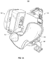
- FIG. 1A illustrates a perspective view of a headset system 100 including a device 130 according to various arrangements.
- FIG. 1B illustrates a perspective view of the headset system 100 illustrated in FIG. 1A without the device 130 according to various arrangements.
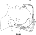
- FIG. 2A , FIG. 2B , and FIG. 2C illustrate views of the headset system 100 illustrated in FIGS. 1A and 1B with a patient's head therein according to various arrangements.
- the dynamic headset system 100 includes a head cradle 110, a restraint system 120, the device 130, and a device attachment mechanism 140, and a mount 150.
- the cradle 110 is configured to receive and support a patient's head (e.g., during operation of the device 130).
- the cradle 110 is capable of accommodating and supporting different head sizes for use in conjunction with the device 130.
- the cradle 110 includes a frame and padding attached to the frame. The frame supports the padding, while the padding is configured to contact a human head.
- the frame of the cradle 110 is shaped to suitably contour and support varying head sizes and shapes, and the frame is also shaped to adequately position a user's head in a workspace of the device 130.
- the frame of the cradle 110 is made from any suitably malleable material that allows for flexing, such as, but not limited to, flexible plastics, polyethylene, urethanes, polypropylene, ABS, nylon, fiber-reinforced silicones, structural foams, or the like.
- the padding of the cradle 110 is made from any suitable soft material, such as, but not limited to, closed cell foam, open cell foam, self-skinning open or closed cell foams, cast, aerated, or extruded silicone or urethane, polyurethane gels that are configured to distribute pressure efficiently, or the like.
- the padding of the cradle 110 has any suitable firmness for supporting a head, such as, but not limited to, in a range of about 0.1 pound per square inch (psi) to about 60 psi (e.g., in a range of about 0.1 psi to about 10 psi) or within other suitable ranges of firmness.
- the padding of the cradle 110 has memory for expanding to fit contours of a head.
- the padding (e.g., foam) of the cradle 110 is compressed and expands after a user's head is placed in the headset system 100 so that the padding expands to secure the headset apparatus 100.
- the cradle 110 including the padding is manufactured by any suitable process for affixing the padding within the headset apparatus 110, such as, but not limited to, injection molding, laminating, adhesive mounting (e.g., gluing or bonding), co-molding, co-casting, injection, snapping, by Velcro fastening, by hook and loop fastening, friction fitting, attaching with barbs, using screw bosses, or the like.
- the padding of the cradle 110 includes an inflatable bladder.
- the bladder is a hollow void that is filled manually or with a pump.
- the inflatable bladder is self-inflating with an internal structure that has a memory and that expands within the bladder to inflate to at least 90% capacity.
- the bladder is inflated to other suitable capacities, such as, but not limited to, at least about 95% capacity, at least about 80% capacity, at least about 70% capacity, and so on.
- inflation is assisted with an integrated pump or an external filling or pumping source.
- the inflatable bladder is filled with air, gas, liquid, or any other suitable element for affixing or securing the inflatable padding of the headset system 100 to a user's head.
- the bladder is filled with plastic beads or pellets. In particular arrangements, the bladder that is filled with plastic beads or pellets becomes rigid, so as to capture a patient's head, when a vacuum is applied to the bladder.
- the restraint system 120 is configured to restrain a subject's head when placed in the cradle 110.
- the restraint system 120 includes a base 121, a body 122, and a contact 123.
- the base 121 is attached to the mount 150.
- the body 122 includes an elongated section that is configured to slide into the base 121, and lock while in the base 121, so as to provide adjustability of the restraint system 120 to accommodate different heads of subjects (e.g., different sizes and shapes).
- the contact 123 is attached to the body 122, and the contact 123 is configured to contact and apply pressure against a subject's head (e.g., forehead) for securing the headset system 100 to the subject.
- the contact 123 is configured to pivot at a location where the contact 123 is attached to the body 122 to provide further adjustability for different sized and shaped heads of subjects.
- the contact 123 includes a padding for contacting a subject's head, and the padding is made from any suitable soft material, such as, but not limited to, closed cell foam, open cell foam, self-skinning open or closed cell foams, cast, aerated, or extruded silicone or urethane, polyurethane gels that are configured to distribute pressure efficiently, or the like.
- the device 130 is modular and can be attached and detached from the headset system 100 via the attachment mechanism 140.
- the headset system 100 is used in conjunction with a medical device for use with respect to a user's head (e.g., an ocular monitoring system, a breathing device, a device for monitoring neurological activity, a surgical device, a device for monitoring radioactive traces, or any other appropriate device).
- the headset system 100 is used in conjunction with a non-medical device for use with respect to a user's head (e.g., a virtual reality eyepiece).
- the device 130 includes a transducer or a probe 131 and robotics for controlling the probe 131, collectively referred to as an "instrument.”
- instrument refers to at least one data collection device (e.g., a probe such as but not limited to, the probe 131) and devices (e.g., positioning components such as but not limited to, the robotics 132) configured to control position and operations (e.g., data collection) of the data collection device.
- the robotics are configured to translate the probe 131 along a surface of a head and to move the probe 131 towards and away from the head.
- an end of the probe 131 interfaces with the robotics, and the robotics include components, such as, but not limited to, a motor assembly and the like for controlling the probe 131 (e.g., control z-axis pressure, normal alignment, or the like of the probe 131).
- the registration of the probe 131 against a subject's head is accomplished using the robotics to properly position and align the probe 131 with the subject's head.
- the probe 131 includes a first end and a second end that is opposite to the first end.
- the first end includes a concave surface that is configured to be adjacent to or contact a scanning surface (e.g., a head of a subject).
- the concave surface is configured with a particular pitch to focus generated energy towards the scanning surface.
- the device 130 is a Transcranial Doppler (TCD) apparatus such that the first end of the probe 131 is configured to be adjacent to or contact and align along a human head (e.g., a side of the human head), and the first end of the probe 131 is configured to provide ultrasound wave emissions from the first end and directed into the human head (e.g., towards the brain).
- TCD Transcranial Doppler
- the probe 131 is an ultrasound probe configured for ultrasound procedures.
- the probe 131 is configured to emit other types of waves during operation, such as, but not limited to, infrared, x-rays, electromagnetic, thermal, near-infrared, optical, lighting, audio, electroencephalography, or the like.
- the second end of the probe 131 is coupled to the robotics.
- the second end of the probe 131 includes a threaded section along a portion of the body of the probe 131, and the second end is configured to be secured in the robotics via the threads (e.g., by being screwed into the robotics).
- the probe 131 is secured in the robotics by any other suitable connecting means, such as, but not limited to, welding, adhesive, one or more hooks and latches, one or more separate screws, press fittings, or the like.
- probe systems that can be used in conjunction with the headsets described herein can be found in non-provisional patent application serial no. 15/399,648 , titled ROBOTIC SYSTEMS FOR CONTROL OF AN ULTRASONIC PROBE, and filed on January 5, 2017.
- the headset system 100 holds other medical and non-medical devices that are used and registered (e.g., positioned or aligned) with respect to a user's head.
- an ocular device is a device that is optimized by being properly positioned and aligned with a user's eyes (e.g., if the ocular device is shifted with respect to a user's eyes, performance of the ocular device may decline).
- the ocular device is attached at the headset system 100 so as to cover the eyes of a patient.
- the headset system 100 can be used in connection with the ocular device that is a virtual reality device configured to provide a virtual experience to the user such that any disturbance of the positioning of the ocular device in front of the user's eyes may cause a degradation in the user's virtual experience.
- the ocular device that is a virtual reality device configured to provide a virtual experience to the user such that any disturbance of the positioning of the ocular device in front of the user's eyes may cause a degradation in the user's virtual experience.
- the ocular device is a medical device designed to track ocular behavior of a subject (e.g., to diagnose whether the user has experienced a concussion).
- the ocular device is an ocular diagnosis or treatment tool for determining or adjusting vision of the user.
- the ocular device is a device for correcting imperfect vision of a user (e.g., laser eye surgery).
- the ocular device is an ocular diagnostic tool for determining a vision prescription of a user, presence of one or more eye conditions (e.g., glaucoma, cataracts, ocular hypertension, uveitis, or the like), and the like.
- the ocular device is designed to cover and interact with both eyes simultaneously or in sequence.
- the ocular device is designed to cover and interact with a single eye (e.g., while the other eye remains uncovered).
- the attachment mechanism 140 is configured to receive and secure the device 130. In other arrangements, the attachment mechanism 140 is configured to receive and secure other medical and non-medical devices (e.g., those discussed above).
- the attachment mechanism 140 includes a track 141 and a slider 142.
- the track 141 receives the slider 142 and the slider 142 is adjustable along the track 141. For example, the slider 142 can slide within the track 141 and can be locked in place at a desired location.
- the attachment mechanism 140 includes two sets of the track 141 and the slider 142, with each set located at an opposite side of the headset system 100. Accordingly, in some arrangements, a plurality of devices 130 can be attached at the headset system 100 for operation with respect to both sides of a subject's head.
- the device 130 is affixed to the slider 142 so that adjustment of the slider 142 results in adjustment of the device 130 with respect to a subject's head (e.g., telescoping adjustment towards and away from the subject's head).
- the bottom of the device 130 is connected to the slider 142.
- the device 130 is affixed to the attachment mechanism 140 by any suitable connection mechanism, such as, but not limited to, welding, adhesive, one or more separate bolts, one or more hooks and latches, one or more separate screws, press fittings, or the like.
- the attachment mechanism 140 (e.g., the track 141 and/or the slider 142) is made from any suitable rigid material, such as, but not limited to, hard plastic, metals, aluminum, steel, titanium, magnesium, various alloys, rigid plastics, composites, carbon fiber, fiber glass, expanded foam, compression molded foam, stereolithography (SLA) or Fused Deposition Modeling (FDM)-made materials, Reaction Injection Molding (RIM) molding, acrylonitrile butadiene styrene (ABS), thermoplastic olefin (TPO), nylon, polyvinyl chloride (PVC), fiber reinforced resins, or the like.
- suitable rigid material such as, but not limited to, hard plastic, metals, aluminum, steel, titanium, magnesium, various alloys, rigid plastics, composites, carbon fiber, fiber glass, expanded foam, compression molded foam, stereolithography (SLA) or Fused Deposition Modeling (FDM)-made materials, Reaction Injection Molding (RIM) molding, acrylonitrile buta
- the mount 150 is affixed to the restraint system 120 (e.g., the base 121), the attachment mechanism 140, and the cradle 110. In some arrangements, one or more of the restraint system 120, the attachment mechanism 140, and the cradle 110 are attached to the mount 150 via a plurality of screws and/or bolts. In other arrangements, one or more of the restraint system 120, the attachment mechanism 140, and the cradle 110 are attached to the mount 150 by any other suitable connecting means, such as, but not limited to, welding, adhesive, one or more hooks and latches, press fittings, or the like.
- one or more of the restraint system 120, the attachment mechanism 140, and the cradle 110 are permanently affixed to the mount 150. In other arrangements, one or more of the restraint system 120, the attachment mechanism 140, and the cradle 110 are releasably attached to the mount 150.
- the mount 150 is made from any suitable rigid material, such as, but not limited to, hard plastic, metals, aluminum, steel, titanium, magnesium, various alloys, rigid plastics, composites, carbon fiber, fiber glass, expanded foam, compression molded foam, SLA or FDM-made materials, RIM molding, ABS, TPO, nylon, PVC, fiber reinforced resins, or the like. Further disclosure regarding the cradle, the mount, and other structural components of the system 100 can be found in non-provisional patent application serial no. 15/853,433 , titled HEADSET SYSTEM, and filed on December 22, 2017, and non-provisional patent application serial no. 16/101,352 , titled DYNAMIC HEADSET APPARATUS, and filed on August 10, 2018.
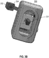
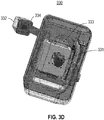
- FIG. 3A illustrates a perspective view of a device 330 included in a headset system according to various arrangements.
- FIG. 3B illustrates a front view of the device 330 illustrated in FIG. 3A according to various arrangements.
- FIG. 3C illustrates a transparent perspective view of the device 330 illustrated in FIG. 3A according to various arrangements.
- FIG. 3D illustrates a transparent front view of the device 330 illustrated in FIG. 3A according to various arrangements.
- the device 330 is an example implementation of the device 130.
- the device 330 is configured to be coupled to the attachment mechanism 140 as described above, for use within the headset system 100 (e.g., similar to the device 130).
- the device 330 includes a transducer or probe 331, a camera 332, and robotics 333.
- the probe 331 is similar to the probe 131, and so the description above with respect to the probe 131 is applicable to the probe 331.
- the probe 331 is coupled to the robotics 333 of the device 330 such that the probe 331 is moved along multiple axes (e.g., x-axis, y-axis, and z-axis), as described above.
- the camera 332 is configured to capture one or more images of a subject's head when the subject's head is placed within the headset system 100 (e.g., within the cradle 110). From the captured one or more images, the subject's head can be registered with respect to the device 330 (e.g., the device 330 can initially position or align the probe 331 for subsequent operation of the probe 331 and the device 330 on the subject's head, restricting or defining the workspace of the probe 331 to certain boundaries during operation of probe 331 and the device 330, and so on). Further details regarding registration of the device 330 is disclosed below.
- the camera 332 is any suitable image capturing mechanism or device for taking images of one or more body parts of the subject (e.g., a subject's head).
- the camera 332 include but are not limited to, a digital camera, a thermal camera, an infrared camera, a night vision camera, and the like.
- the camera 332 can have any suitable resolution and focal length for capturing desired images configured to our can be suitable for registering a subject's head (e.g., about 5 megapixels and about 4 millimeter (mm) focal length).
- the resolution and/or the focal length of the camera 332 is fixed or predetermined. In other arrangements, the resolution and/or the focal length are variable.
- the camera 332 moves (e.g., extends) from a main body of the device 330 (e.g., a portion of the device 330 housing the robotics 333 and the probe 331) and is rigidly mounted to the device 330 (e.g., to a portion of the main body of the device 330 configured to extend from the main body).
- the camera 332 is adjustable with respect to the main body of the device 330 (e.g., the camera 332 can pivot, rotate, shift, and the like relative to the main body).
- the camera 332 is positioned or moved (e.g., extended, pivoted, rotated, or shifted) automatically by a controller (a controller 408 of FIG. 4 ) or by an operator manually such that particular anatomical locations of a subject's head are within a field of view of the camera 332 when the subject's head is held within the headset system 100, and such that the device 330 or any other portion of the headset system 100 does not obstruct the field of view of the camera 332.
- the subject's tragus and eye are configured to be visible to the camera 332 when the subject's head is held within the headset system 100.
- the relative location and rotation of the camera 332 relative to the workspace of the probe 331 and the robotics 333 is a known and fixed parameter that can be utilized to register the device 330 with respect to a subject's head, as further discussed below.
- an exposure time of the camera 332 is adjustable (e.g., manually adjustable by an operator).
- the camera 332 includes an illumination source 334 configured to emit light to be irradiated upon the subject's head to allow the camera 332 to take one or more images of the subject's head.
- the illumination source 334 includes one or more illuminators (e.g., one or more light-emitting diodes (LEDs), one or more fluorescent lights, one or more Ballast lights, one or more halogen lights, one or more neon lights, and the like).
- the illumination source 334 includes any desired number of illuminators for suitably illuminating a subject's head such that the camera 332 can obtain images of a subject's head, as described herein.
- the illumination source 334 can include a plurality of illuminators (e.g., two, four, eight, twelve, or more illuminators).
- the light emitted from the illumination source 334 has a suitable wavelength for being captured by the camera 332, such as, but not limited to, that of infrared light (e.g., light having a wavelength of 850 nanometers (nm)).
- the camera 332 is sensitive to light having a wavelength of that of light emitted by the illumination source 334 (e.g., the camera 333 is sensitive to infrared light).
- the illuminators of the illumination source 334 are safe enough to irradiate light upon eyes of subjects and operators for a suitable amount of time at a suitable distance (e.g., for 1000 seconds at a distance of 50 mm or greater).
- a suitable distance e.g., for 1000 seconds at a distance of 50 mm or greater.
- the camera 332 e.g., a night vision camera, an infrared camera, a thermal camera, and so on
- the camera 332 e.g., a night vision camera, an infrared camera, a thermal camera, and so on
- the illumination source 334 includes a printed circuit board (PCB) on which the illuminators are located.
- the PCB includes an opening for allowing the lens of the camera 334 to pass therethrough.
- the illuminators are arranged to be evenly spaced (e.g., in a circular formation) around the lens of the camera 334, and the illuminators are further positioned to be as close as possible to the outer diameter of the lens of the camera 334.
- the brightness of the illumination source 334 is adjusted using Pulse Width Modulation (PWM) and can be adjusted by an operator or can be automatically adjusted (e.g., based on brightness of ambient light).
- PWM Pulse Width Modulation
- the illuminators are powered in an on state when a frame exposure of the camera 334 is active.
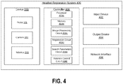
- FIG. 4 illustrates a block diagram of a headset registration system 400 according to various arrangements.
- the headset registration system 400 is an example implementation of the headset system 100 and includes the device 330 including the probe 331, the camera 332, and the robotics 333, which are described herein.
- the headset registration system 400 further includes an input device 402, an output device 404, and a network interface 406.
- the input device 402 includes any suitable device configured to allow an operator to input information or commands into the headset registration system 400.
- the input device 402 includes, but is not limited to, a keyboard, a keypad, a mouse, a joystick, a touchscreen display, or any other input device performing a similar function.
- the output device 404 includes any suitable device configured to display information, results, messages, and the like to an operator concerning the headset registration system 400.
- the output device 404 includes, but is not limited to, a computer monitor, a printer, a facsimile machine, or any other output device performing a similar function.
- the input device 402 and the output device 404 are the same device (e.g., a touchscreen display device).
- the network interface 406 is structured for sending and receiving data over a communication network (e.g., results, instructions, requests, software or firmware updates, and the like).
- the network interface 406 includes any of a cellular transceiver (for cellular standards), local wireless network transceiver (for 802.11X, ZigBee, Bluetooth, Wi-Fi, or the like), wired network interface, a combination thereof (e.g., both a cellular transceiver and a Bluetooth transceiver), and/or the like.
- the headset registration system 400 includes a controller 408 for controlling operations, processing data, executing input commands, providing results, and the like with respect to the headset registration system 400.
- the controller 408 is configured to receive input data or instructions from the input device 402 or the network interface 406, control the device 330 to execute the commands, receive data from the device 330, provide information to the output device 404 or network interface 406, and so on.
- the controller 408 includes a processor 408a, memory 408b, an image processing circuit 408c, a registration circuit 408d, a search parameters circuit 408e, and a robotics control circuit 408f.
- the headset system 100 includes a plurality of cameras 332 (e.g., at each side of the headset system 100) such that the headset system 100 is bilateral and such that images of both sides of a subject's head are captured.
- the captured images are processed at the single controller 408 (e.g., each of the left and right images of the subject's head is processed independently at the controller 408).
- the processor 408a is implemented as a general-purpose processor and is coupled to at least one memory 408b.
- the processor 408a includes any suitable data processing device, such as a microprocessor.
- the processor 408a includes any suitable electronic processor, controller, microcontroller, or state machine.
- the processor 408a is implemented as a combination of computing devices (e.g., a combination of a Digital Signal Processor (DSP) and a microprocessor, a plurality of microprocessors, at least one microprocessor in conjunction with a DSP core, or any other such configuration).
- the processor 408a is implemented as an Application Specific Integrated Circuit (ASIC), one or more Field Programmable Gate Arrays (FPGAs), a Digital Signal Processor (DSP), a group of processing components, or other suitable electronic processing components.
- ASIC Application Specific Integrated Circuit
- FPGAs Field Programmable Gate Arrays
- DSP Digital Signal Processor
- the memory 408b includes a non-transitory processor-readable storage medium that stores processor-executable instructions.
- the memory 408b includes any suitable internal or external device for storing software and data. Examples of the memory 408b can include, but are not limited to, Random Access Memory (RAM), Read-Only Memory (ROM), Non-Volatile RAM (NVRAM), flash memory, floppy disks, hard disks, dongles or other Recomp Sensor Board (RSB)-connected memory devices, or the like.
- the memory 408b can store an Operating System (OS), user application software, and/or executable instructions.
- the memory 408b can also store application data, such as an array data structure. In some arrangements, the memory 408b stores data and/or computer code for facilitating the various processes described herein.
- the term "circuit" can include hardware structured to execute the functions described herein.
- each respective circuit can include machine-readable media for configuring the hardware to execute the functions described herein.
- the circuit can be embodied as one or more circuitry components including, but not limited to, processing circuitry, network interfaces, peripheral devices, input devices, output devices, sensors, etc.
- a circuit can take the form of one or more analog circuits, electronic circuits (e.g., integrated circuits (IC), discrete circuits, system on a chip (SOCs) circuits, etc.), telecommunication circuits, hybrid circuits, and any other suitable type of circuit.
- the circuit can include any type of component for accomplishing or facilitating achievement of the operations described herein.
- a circuit as described herein can include one or more transistors, logic gates (e.g., NAND, AND, NOR, OR, XOR, NOT, XNOR, etc.), resistors, multiplexers, registers, capacitors, inductors, diodes, wiring, and so on.
- logic gates e.g., NAND, AND, NOR, OR, XOR, NOT, XNOR, etc.
- resistors e.g., resistors, multiplexers, registers, capacitors, inductors, diodes, wiring, and so on.
- the circuit can also include one or more processors communicatively coupled to one or more memory or memory devices.
- the one or more processors can execute instructions stored in the memory or can execute instructions otherwise accessible to the one or more processors.
- the one or more processors can be embodied in various ways.
- the one or more processors can be constructed in a manner sufficient to perform at least the operations described herein.
- the one or more processors can be shared by multiple circuits (e.g., a first circuit and a second circuit can comprise or otherwise share the same processor which, in some example arrangements, can execute instructions stored, or otherwise accessed, via different areas of memory).
- the one or more processors can be structured to perform or otherwise execute certain operations independent of one or more co-processors.
- two or more processors can be coupled via a bus to enable independent, parallel, pipelined, or multi-threaded instruction execution.
- Each processor can be implemented as one or more general-purpose processors, ASICs, FPGAs, DSPs, or other suitable electronic data processing components structured to execute instructions provided by memory.
- the one or more processors can take the form of a single core processor, multi-core processor (e.g., a dual core processor, triple core processor, quad core processor, etc.), microprocessor, etc.
- the one or more processors can be external to the apparatus, for example, the one or more processors can be a remote processor (e.g., a cloud-based processor). Alternatively, or additionally, the one or more processors can be internal and/or local to the apparatus.
- a given circuit or components thereof can be disposed locally (e.g., as part of a local server, a local computing system, etc.) or remotely (e.g., as part of a remote server such as a cloud-based server).
- a circuit, as described herein can include components that are distributed across one or more locations.
- An example system for implementing the overall system or portions of the arrangements can include a general-purpose computer, including a processing unit, a system memory, and a system bus that couples various system components including the system memory to the processing unit.
- Each memory device can include non-transient volatile storage media, non-volatile storage media, non-transitory storage media (e.g., one or more volatile and/or non-volatile memories), etc.
- the non-volatile media may take the form of ROM, flash memory (e.g., flash memory such as NAND, 3D NAND, NOR, 3D NOR, etc.), Electrically Erasable Programmable Read-Only Memory (EEPROM), Magnetoresistive Random Access Memory (MRAM), magnetic storage, hard discs, optical discs, etc.
- the volatile storage media can take the form of RAM, Thyristor Random Access Memory (TRAM), Z-Capacitor Random Access Memory (ZRAM), etc.
- machine-executable instructions comprise, for example, instructions and data which cause a general-purpose computer, special purpose computer, or special purpose processing machines to perform a certain function or group of functions.
- Each respective memory device can be operable to maintain or otherwise store information relating to the operations performed by one or more associated circuits, including processor instructions and related data (e.g., database components, object code components, script components, etc.), in accordance with the example arrangements described herein.
- processor instructions and related data e.g., database components, object code components, script components, etc.
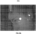
- FIG. 5A illustrates an image 500a, which is an example of an image that can be taken by the camera 332 of the device 330 according to various arrangements.
- the image processing circuit 408c is configured to receive image data taken by the camera 332 (e.g., an image depicting a side of a subject's head).
- the image captured by the camera 332 includes a two-dimensional array of pixel brightness values.
- the subject's head has fiducial markers (or fiducials) disposed by an operator at anatomically significant locations such that the image includes the subject's head with the fiducials.
- the fiducials are disposed at anatomically significant locations so as to signify the boundaries of the workspace of the device 330 during operation, and the fiducials are configured to be detected by the image processing circuit 408c.
- the fiducials are disposed at a corner of a subject's eye and at the tragus of the subject.
- anatomical markers e.g., ears and eyes
- at least one image per lateral side of the subject's head can be obtained after placement of at least one fiducial on either lateral side of the subject's head.
- fiducial markers can be any nature anatomy landmarks such as but not limited to, the eyes, the nose, the ear, the forehead, the eyebrow, the mouth, the lips, the hairline, the collar bone, the navel, the nipples, any joints, fingernails, and the like.
- the image 500 depicts a first fiducial 502a and a second fiducial 502b.
- any suitable number of fiducials can be disposed on a subject, such as, but not limited to, one fiducial or three or more fiducials.
- the fiducials 502a, 502b are adhesive stickers having a fixed, known, or predetermined size, shape, color, and design to allow the controller 408 to identify the fiducials 502a and 502b.
- all fiducials disposed on the body of the subject have the same size, shape, color, and design.
- the controller 408 is preprogrammed with the fiducials characteristics such as the size, shape, color, and design to identify the fiducials from the captured images.
- the fiducials 502a, 502b include a circular retroreflective material and a surrounding black ring.
- the circular retroreflective material and the surrounding black ring of each of the fiducials 502a, 502b are on a surface opposite of the surface on which adhesive is provided, such that the circular retroreflective material and the surrounding black ring are configured to the camera 332 when the fiducials 502a, 502b are placed on the head of the subject.
- the retroreflective fiducials 502a, 502b are capable of reflecting light back to a source of the light (e.g., the illumination source 334) with minimal scattering.
- a source of the light e.g., the illumination source 334.
- an electromagnetic wavefront incident on the fiducials 502a, 502b is reflected back along a vector that is parallel to but opposite in direction from the wave's source.
- the fiducials 502a, 502b are consumable or disposable items.
- fiducials 502a, 502b are described to have a circular shape, other shapes such as but not limited to, a square, a rectangle, a triangle, a cross, a star, or another complex design that can be easily distinguished from other shapes present on the body of the subject by the controller 408.
- An example of a complex design is a square within a circle, which is within a triangle.
- the size of the fiducials 502a, 502b is a known and controlled parameter that is utilized by the controller 408 during image processing and registration.
- each of the fiducials 502a, 502b has a distinctive boundary (e.g., a black boundary) that is made from a material that is not heavily reflective or minimally reflective such that there can be a high contrast between the retroreflective material and its minimally-reflective boundary during illumination of the subject's head (e.g., by the illumination source 334).
- the boundary is around an outer perimeter of each of the fiducials 502a and 502b.
- each of the fiducials 502a, 502b includes an adhesive backing for application to a subject's skin such that the fiducials 502a, 502b sufficiently remain in place during operation of the device 330.
- the color, the shape, and design of the fiducials 502a, 502b is a known and controlled parameter that is utilized by the controller 408 during image processing and registration.
- the image processing circuit 408c is configured to process the images taken by the camera 332 (e.g., by detecting the fiducials 502a, 502b captured in the image 500a).
- the image 500a is preprocessed to smooth the image 500a. For example, a blue filter can be applied to the image 500a to smooth out the effects of noise that is typically present in a digital image.
- the image processing circuit 408c is configured to create one or more binary images from the preprocessed image (e.g., the digital image).
- a threshold-based binary image is created, for example, in which a value of each pixel of the image 500a whose brightness is above a predetermined brightness threshold is set to 255 and a value of each pixel whose brightness is below the predetermined brightness threshold is set to 0.
- an edge detection-based binary image is created, for example, by using a Canny edge detection process, in which a pixel of the image 500a is set to a 1 if it lies upon a part of the image 500a recognized as being an edge in the preprocessed image and a 0 if the pixel is detected as not lying upon an edge.
- any suitable edge detection process can be used to create the edge detection-based binary image.
- the threshold-based binary image is created, while the edge detection-based binary image is not created.
- the edge detection-based binary image is created, while the threshold-based binary image is not created.
- both the threshold-based binary image and the edge detection-based binary image are created.
- the one or more generated binary images are post-processed.
- a dilation filter and/or an erosion filter are applied to the binary images such that white regions are grown and/or shrunk, respectively, as desired.
- contours within the one or more generated binary images are detected, and of the detected contours, those (fiducial contours) that are proper fiducials are selected.
- Unselected contours may belong to artifacts created by backgrounds of the images or light reflections on the subject's face.
- each contour is replaced with its convex hull such that the contour is a closed shape with a well-defined area, and a best fit ellipse is computed for each contour.
- different detected contours that have best fit ellipses that are the same size and that have the same center point are consolidated and treated as being the same contour.
- contours each having a ratio of their area to their perimeter are rejected (e.g., if the area to perimeter ratio of a contour differs by more than a predetermined threshold amount from the area to perimeter ratio for a perfect circle, the contour is rejected). For example, this is because each of the fiducials 502a, 502b is known to be implemented as a perfect circle in some arrangements.
- fiducials of other shapes such as but not limited to, a square, a rectangle, a triangle, a cross, a star, or another complex design can be identified based on an acceptable deviation threshold with respect to each respective shape similar to described herein with respect to a perfect circle.
- ellipses having an area outside a predetermined range of values are rejected (e.g., a range of values corresponding to the known areas of the fiducials 502a, 502b).
- contours that have an area that differs by greater than a threshold ratio from an area of the best fit ellipse are rejected.
- any one or more (or all) of the above-described contour and ellipse rejection processes are utilized.
- contours such as the ellipses that are detected as being present in both the threshold-based binary image and the edge detection-based binary image are accepted.
- ellipses are identified as being present in both images if ellipse center points that are detected in each binary image are determined to be within a predetermined range of one another.
- the results of the image processing operation include a collection of feature tuples capturing location and size of pixels of each fiducial in an image.
- the fiducial size to proceed with is selected based on the sizes detected in each binary image, for example, in a case where the threshold-based binary image and the edge detection-based binary image are in conflict regarding fiducial size.
- the fiducials e.g., sizes of fiducials
- the fiducials of the edge detection-based binary image are always selected.
- the smaller-sized fiducials are always selected, the larger-sized fiducials are always selected, a mean of the differing-sized fiducials are selected, and so on.
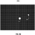
- FIG. 5B illustrates a binary image 500b after the image 500a shown in FIG. 5A undergoes image processing according to various arrangements.
- the image processing circuit 408c is configured to generate the binary image 500b that distinctly identifies and locates the fiducials 502a, 502b.
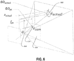
- FIG. 6 illustrates a three-dimensional view of a spatial relationship between the camera 332 ( FIG. 3 ), a virtual image of the camera 332, and a fiducial according to various arrangements.
- the image processing circuit 408c is configured to represent locations within an image (e.g., the binary image 500b) as pixel coordinate values (u, v) within the image.
- the top left-hand position of an image is designated as coordinates (0, 0), while the u-coordinate value increases along with movement towards the right-hand side of the image and the v-coordinate value increases along with movement towards the bottom of the image.
- any other suitable coordinate system is used to identify locations within an image (e.g., (0, 0) can be located at the bottom right-hand corner of the image, while movement towards the left-hand side increases the u-coordinate value and movement towards the top of the image increases the v-coordinate value, and so on).
- the image processing circuit 408c transforms these image coordinates into homogenous camera coordinates using a camera intrinsics matrix and camera distortion coefficients of the camera 332, which are known parameters that can be computed based on a camera calibration procedure of the camera 332.
- the image processing circuit 408c is configured to determine a physical unit distance associated with a homogenous camera coordinate vector.
- FIG. 6 shows a real-world fiducial 602, a virtual image fiducial 604 at a virtual camera image 606, and a camera origin 608.
- v ⁇ cam represents a vector from the camera origin 608 to the location of the virtual image fiducial 604 and v ⁇ actual represents a vector from the camera origin 608 to the location of the real-world fiducial 602.
- ⁇ px represents the focal length of the camera 332 (e.g., measured in units of a pixel size of the sensor of the camera 332), which is a known parameter.
- ⁇ D px represents a diameter of the virtual image fiducial 604 (e.g., in pixels) and ⁇ D actual represents a diameter of the real-world fiducial 602, which are both known parameters.
- z actual represents a distance from the camera origin 608 to the real-world fiducial 602.
- the image processing circuit 408c is configured to determine v ⁇ actual based on the above equation and the known parameters. For example, in particular arrangements, the virtual camera image 606 is located at a distance ⁇ px from the camera origin 608. Accordingly, in some arrangements, using similar triangles, and knowing ⁇ px , ⁇ D px , and ⁇ D actual , the image processing circuit 408c is configured to determine z actual . In further arrangements, the image processing circuit 408c is configured to multiply v ⁇ cam by a scalar constant such that the z-coordinate component of v ⁇ cam equals z actual , which results in v ⁇ actual .
- the image processing circuit 408c is configured to utilize the optical parameters of the camera 332 and the known size of the fiducial 602 to determine the location of the fiducial 602 relative to the camera 332. In further arrangements, the image processing circuit 408c is configured to apply boundary limits to ensure that the detected position of the fiducial 602 falls within a reasonable predetermined range of positions relative to the camera 332 for actual use.
- the registration circuit 408d is configured to transform the camera coordinates (e.g., v ⁇ actual ) obtained by the image processing circuit 408c into robot coordinates for use by the robotics control circuit 408f in controlling the robotics 333 for positioning the probe 331 during operation of the device 330.
- transformations between the camera coordinate system and the robot coordinate system are performed using homogenous coordinates.
- the registration circuit 408d stores a coordinate transformer class that stores a relationship between camera coordinates and robot coordinates (e.g., a coordinate transformation matrix that is a 4x4 matrix).
- positions in camera coordinates are represented as a 3x1 vector (e.g., v ⁇ actual ), and the registration circuit 408d is configured to convert the 3x1 camera coordinates into a homogenous coordinate representation by appending a 4 th coordinate having a value of 1 (e.g., [x, y, z] becomes [x, y, z, 1]).
- the registration circuit 408d is configured to multiply the homogenous coordinate-represented camera coordinate vector by the stored coordinate transformation matrix to obtain a homogenous robot coordinate vector.
- the coordinate transformation matrix that facilitates transformation of camera coordinates into robot coordinates is of the form: R t 0 1
- R is a 3x3 rotation matrix for applying a change in orientation between the camera coordinate system and the robot coordinate system
- t is a translation between the origin of the robot coordinate system and the camera coordinate system (e.g., expressed as a 3x1 vector in the robot coordinate system).
- the inverse of the coordinate transformation matrix can be utilized to transform the robot coordinates into the camera coordinates.
- the registration circuit 408d is configured to utilize the known spatial relationship between the origin of the workspace of the robotics 333 and the origin of the camera 332 to transform locations relative to the camera 332 into locations relative to the robotics 333.
- the registration circuit 408d is configured to apply additional boundary limits to ensure that the detected positions of the fiducials fall within a reasonable range of positions relative to the origin of the workspace of the robotics 333 for actual use.
- the detected fiducials are displayed to an operator for confirmation that the fiducials are properly detected. For example, one or more of the preprocessed images (e.g., the image 500a) and the binary images (e.g., the image 500b) can be displayed by the output device 404.
- the selected contours corresponding to the fiducials can be superimposed onto a preprocessed image to be displayed to the operator.
- the fiducials 502a and 502b as shown in FIG. 5A can be displayed in a graphical state that emphasizes the fiducials 502a and 502b by highlighting the fiducials 502a and 502b, adjusting brightness of the fiducials 502a and 502b, and the like, such that the operator can easily see that the contours corresponding to the fiducials 502a and 502b are correctly recognized.
- the input device 402 may provide a user interactive element (e.g., a soft switch, a button, a dial, or the like) to allow the operator to confirm that the fiducials 502a and 502b are correctly recognized or to reject the selected contours.
- the controller 408 e.g., the registration circuit 408d
- the controller 408 is configured to transform the camera coordinates into robot coordinates for use by the robotics control circuit 408f in controlling the robotics 333 for positioning the probe 331 during operation of the device 330 in the manner described.
- the fiducial detection method as described herein can be re-run.
- the search parameters circuit 408e is configured to generate a search pattern and path of scanning for the probe 331, including identifying an optimal scanning starting position, during scanning operation of the device 330.
- the search parameters circuit 408e in generating the search pattern and path, utilizes the allowable robot workspace determined by the registration circuit 408d, as described above.
- the positions of the detected fiducials are received by the search parameters circuit 408e as reference points to restrict the search area of the probe 331 and to guide the search.
- the search parameters circuit 408e instructs the robotics control circuit 408f regarding positioning and travel path of the probe 331 during operation of the device 330 so that the robotics control circuit 408f can send corresponding control signals to the robotics 333 for physically controlling the probe 331.
- a subject's head having fiducials attached thereto at anatomically relevant locations is received in the headset system and one or more images of the subject's head are captured.
- Image processing is utilized to detect the fiducials.
- the detected fiducials are displayed to an operator for confirming that the detected locations of the fiducials are correct.
- the locations of the fiducials in camera coordinates are determined in robot coordinates within the robot workspace, and search parameters utilize the positions of the fiducials to restrict travel of the probe (e.g., to avoid certain areas within the robotic workspace) and to select an optimal position within the workspace to begin scanning by the probe.
- systems and methods for registering the headset system described herein allows for registration of a robotic probe with respect to a subject's anatomy (e.g., corner of the eye and tragus).
- systems and methods described herein reduce setup time of a headset system in preparation of a scan, while increasing accuracy of scans by repeatable and accurate positioning of a probe by consistently guiding the probe to scan at anatomically relevant positions.
- systems and methods described herein increase safety of a headset system by explicitly restricting movement of the headset system with respect to a subject's anatomy (e.g., by preventing the probe from travelling beyond locations anterior from the corner of the eye).
- systems and methods of registering a headset system can determine from where a signal scanned by a probe is originating from based on a current position of the probe in robot coordinates within the robotic workspace. For example, based on the current position of the probe, the system can determine that the probe is capturing signals originating from the middle cerebral artery (MCA) of the brain.
- MCA middle cerebral artery
- a distance from a camera can be established as a predetermined value (e.g., as if imaging a flat surface at a known distance).
- the distance from the camera can be input by an operator.
- the operator can simply select one or more points on an image captured by the camera, and the system can determine robot coordinates of each of the one or more coordinates based on the predetermined distance from the camera.
- systems and methods of registering a subject's head within a headset system implement machine vision to automatically detect locations of anatomically significant landmarks of a subject's head (e.g., the corner of the eye and the tragus).
- the machine vision can utilize machine learning techniques to analyze various images of subject heads to train the system in identifying the anatomically significant landmarks.
- Training sets including images and corresponding results (e.g., identified landmarks) as determined by a human operator can be used to train the artificial intelligence (e.g., the AI) to identify anatomically significant landmarks.
- the controller 408 can be used to implement a classifier that accepts images of body parts of the subject and outputs identified anatomically significant landmarks.
- systems include a plurality of cameras (e.g., two) at a single side of the headset system such that stereo vision is implemented in determining distances of locations at a head of a subject (e.g., by taking an image of a single point by two different and physically separate cameras).
- a positioning stage attached to a single camera can be utilized for taking multiple images of a point to implement stereo vision (e.g., the single camera takes a first image, the positioning stage moves the camera, and the same camera takes a second image).
- the single camera is attached to the robotics of the scanning device such that the camera can be moved around for implementing stereo vision (e.g., along with the probe).
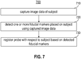
- FIG. 7 is a flowchart diagram illustrating an example method 700 for registering a probe (e.g., the probe 131 of FIGS. 1A and 2B and/or the probe 331 of FIGS. 3A-4 ) of a headset system (e.g., the headset system 100 of FIG. 1 and/or the headset registration system 400 of FIG. 4 ) with respect to a subject according to various arrangements.
- a probe e.g., the probe 131 of FIGS. 1A and 2B and/or the probe 331 of FIGS. 3A-4
- a headset system e.g., the headset system 100 of FIG. 1 and/or the headset registration system 400 of FIG. 4
- image data e.g., one or more images
- the camera 332 e.g., the camera 332
- the controller 408 is configured to detect one or more fiducial markers (e.g., the fiducials 502a and 502b) placed on the subject using the captured image data in the manner described.
- the controller 408 is configured to register the probe with respect to the subject based on the detected fiducial markers in the manner described. While a lateral side of the subject is described as a body part of interest for the method 700 (e.g., the camera 332 captures images of the lateral side of the subject at 710, and the images are analyzed for registration in the manner described with respect to 720 and 730), the method 700 can be implemented with respect to any suitable body part of the subject.
- the camera 332 can be positioned at and/or moved relative to any suitable body part, such that the images of that body part can be captured by the camera 332 and analyzed in the manner described herein.
- FIG. 8 is a flowchart diagram illustrating an example method 800 for determining a fiducial pair (e.g., the fiducials 502a and 502b) according to various arrangements.
- the method 800 is an example method by which a pair of fiducials (e.g., the fiducials 502a and 502b) can be detected at block 720, assuming that a pair of fiducials are placed on a lateral side of a head of a subject.
- the controller 408 e.g., the image processing circuit 408c
- the controller 408 is configured to identify candidate regions.
- candidate regions e.g., candidate elliptic regions
- c 1 , c 2 , ..., c n can be identified using Maximally Stable Extremal Regions (MSER) algorithm, which accepts as inputs two images of a given lateral side of the subject's head that are from different viewpoints.
- MSER Maximally Stable Extremal Regions
- An MSER algorithm can be used to detect elliptic regions in images. As described, a single camera can be moved to take two images of a given lateral side of the subject's head from different viewpoints. Alternatively, two cameras at different positions (different viewpoints) can each take an image of the lateral side of the subject's head.
- each candidate region can be represented by a list of pixels that make up the respective candidate region.
- each candidate region can be approximated by an ellipse obtained through suitable fitting algorithms. Some of the candidate regions corresponding to fiducials. Other candidate regions correspond to artifacts created by backgrounds of the images or light reflections on the subject's face.
- the controller 408 e.g., the image processing circuit 408c
- the controller 408 is configured to sort the identified candidate regions into candidate region pairs, each candidate region pair includes two candidate regions. For example, all permutations of pairings of the candidate regions can be determined.
- the controller 408 e.g., the image processing circuit 408c is configured to determine features for candidate region pair.
- the features can be a feature of each individual candidate region in the pair, or a relative feature indicative of a relative property of the pair.
- each candidate region e.g., each candidate elliptic region
- Location refers to a location of a fiducial in the images 500a and/or 500b as represented with the pixel coordinate values (u, v) described herein.
- Size refers to a total area of an ellipse fitted to a candidate region.
- Eccentricity refers to a ratio between lengths of two axes of an ellipse fitted to a candidate region.
- Intensity refers to an intensity distribution within a candidate region determined using an average value in some examples, and in alternative examples, the intensity distribution within the candidate region can be determined by using a histogram. In constructing the histogram, all have the same limits (e.g., minimum and maximum values) and that normalization is applied to pixels inside of the candidate region. A histogram for each candidate region in the image is generated, where all of those histograms have the same limits.
- intensity surrounding an ellipse corresponding to a candidate region can be described using an average value or a histogram in the manner described.
- An outer region that surrounds the ellipse can be defined by an elliptic ring based on the outer boundary of the inner ellipse and its copy scaled by 175%. That is, in addition to the intensity inside the ellipse, the intensity of an elliptical annulus or ring of an inner major axis and a minor axis equal to the major axis and minor axis of the elliptical region, respectively. An outer major axis and a minor axis equal to 175% of the major and minor axes of the elliptical region, respectively.
- an ideal shape of a fiducial is a perfect circle.
- the perfect circle may appear as an ellipsoid shape in the images 500a and/or 500b.
- a shape descriptor e.g., a general shape descriptor, a shape context descriptor, or the like
- Local texture refers to an appearance of a candidate region as represented using a texture descriptor.
- an image gradient is extracted within an ellipse corresponding to the candidate region, where the image gradient can be summarized as a histogram, for example, using a suitable technique such as but not limited to, Speeded Up Robust Features (SURF).
- SURF Speeded Up Robust Features
- two fiducials can be assumed to be present in any images captured by the camera (if the camera is properly position).
- Features indicative of the relationship between two candidate regions can be used to determine whether a pair of candidate regions can be the two fiducials.
- spatial relation between two candidate regions or two ellipses corresponding thereof can be used to distinguish the fiducials from artifacts.
- Relative position refers to a distance and a slope between the two candidate regions.
- the controller 408 (e.g., the image processing circuit 408c) is configured to determine a probability that each of the candidate region pairs corresponds to the fiducials placed on the subject.
- the controller 408 (e.g., the image processing circuit 408c) is configured to select the candidate region pair having the highest probability of being the fiducials.
- a probabilistic framework can be established to select a pair of the candidate regions as fiducials based on the features such as but not limited to, one or more of a location, size, shape, image intensity, local texture, and spatial relationship.
- the features can be described in a feature vector with respect to each pair of candidate regions (c i , c j ), such as but not limited to, in the form F i,j ⁇ [features, features i , and features ij ].
- the term features ij refers to relative features such as but not limited to, the spatial relationship (in terms of distance and/or slope) between two candidate regions.
- features i refers to features (e.g., one or more of the location, size, shape, image intensity, and local texture) of a first candidate region of the candidate region pair.
- features j refers to features (e.g., one or more of the location, size, shape, image intensity, and local texture) of a second candidate region of the candidate region pair.
- the weights for each of the features can be determined using machine learning.
- manually label training set e.g., data examples
- a probabilistic mapping for each individual feature can be determined based on machine learning.
- a value of each feature is mapped by a probabilistic model to output a value that represents how likely the feature belongs to a fiducial in terms of a probability.
- the probability of all features are combined, for example, using a regression model to determine a final predicted score for each pair of candidate regions. The pair with the highest score is selected.
- the data examples in the training set can be used to determine ⁇ and ⁇ .
- ⁇ and ⁇ are the mean of that feature in the training set and the standard deviation in the training set.
- Kernel Density Estimation can be used as a probabilistic model for each given feature.
- the overall probability for a candidate region pair can be determined by combining (e.g., multiplying) the probability for each feature (individual or relative).
- all features may not contribute equally to correct prediction.
- the features can be weighted, for example, using regression techniques.
- a ridge regression model can be implemented, where the weights are estimated from examples of labeled regions of actual physically tested examples and from the training data set.
- kernel ridge regression can be used instead of the ridge regression.
- the methods 700 and 800 are described with reference to images (e.g., the images 500a and 500b) of lateral sides of a subject's head, the methods 700 and 800 can be implemented with respect to other body parts of the subject such as but not limited to, a front side of the face of the subject (e.g., to obtain ultrasound signals of the head of the subject), chest (e.g., to obtain ultrasound signals of the heart), torso (e.g., to obtain ultrasound signals of various organs), limbs (e.g., to obtain ultrasound signals of blood flow in the limbs), and so on.
- a front side of the face of the subject e.g., to obtain ultrasound signals of the head of the subject
- chest e.g., to obtain ultrasound signals of the heart
- torso e.g., to obtain ultrasound signals of various organs
- limbs e.g., to obtain ultrasound signals of blood flow in the limbs
- fiducials e.g., the fiducials 502a and 502b
- the anatomic features can be identified without using any fiducials.
- the camera 332 may capture images of body parts of the subject (without any fiducials attached thereto).
- the controller 408 e.g., the image processing circuit 408c
- image processing and image recognition techniques e.g., machine vision
- any other suitable technique or device for locating and detecting distances of areas of a subject's head from a scanning device can be implemented during the registration process, such as, but not limited to, structured light, time of flight cameras, time of flight sensors, infrared sensors, and so on.
- a thermal camera is utilized to take an infrared image of the subject's head such that direct visualization of the subject's suitable scanning area (e.g., temporal window) is obtained.
- the systems 100 and 400 as described herein is used in conjunction with other diagnostic ultrasound procedures, such as, but not limited to, needle guidance, intravascular ultrasound (e.g., examination of vessels, blood flow characteristics, clot identification, emboli monitoring, and so on), echocardiograms, abdominal sonography (e.g., imaging of the pancreas, aorta, inferior vena cava, liver, gall bladder, bile ducts, kidneys, spleen, appendix, rectal area, and so on), gynecologic ultrasonography (e.g., examination of pelvic organs such as uterus, ovaries, Fallopian tubes, and so on), obstetrical sonography, otolaryngological sonography (e.g., imaging of the thyroid (such as for tumors and lesions), lymph nodes, salivary glands, and so on), neonatal sonography (e.g., assessment of intracerebral structural abnormalities through soft spots of a skull of an infant,
- the systems 100 and 400 as described herein is used in conjunction with therapeutic ultrasound procedures, such as, but not limited to, high-intensity focused ultrasound (HIFU), focused ultrasound surgery (FUS), Magnetic resonance-guided focused ultrasound (MRgFUS), lithotripsy (e.g., breaking up kidney stones, bezoars, gall stones, and the like), targeted ultrasound drug delivery, trans-dermal ultrasound drug delivery, ultrasound hemostasis, cancer therapy, ultrasound-assisted thrombolysis, dental hygiene (e.g., cleaning teeth), phacoemulsification, ablation (e.g., of tumors or other tissue), acoustic targeted drug delivery (ATDD), trigger release of drugs (e.g., anti-cancer drugs), ultrasound-guided treatments (sclerotherapy, endovenous laser treatment, liposuction, and so on), and the like.
- HIFU high-intensity focused ultrasound
- FUS focused ultrasound surgery
- MgFUS Magnetic resonance-guided focused ultrasound
- lithotripsy
- ultrasound is used for physical therapy applications, including, but not limited to, stimulating tissue beneath the skin's surface (e.g., by using very high frequency sound waves, such as, as an example, between about 800,000 Hz and 2,000,000 Hz), treating musculoskeletal ailments with ultrasound exposure (e.g., ligament sprains, muscle strains, tendonitis, joint inflammation, plantar fasciitis, metatarsalgia, facet irritation, impingement syndrome, bursitis, rheumatoid arthritis, osteoarthritis, and scar tissue adhesion), and the like.
- very high frequency sound waves such as, as an example, between about 800,000 Hz and 2,000,000 Hz
- ultrasound exposure e.g., ligament sprains, muscle strains, tendonitis, joint inflammation, plantar fasciitis, metatarsalgia, facet irritation, impingement syndrome, bursitis, rheumatoid arthritis, osteoarthritis, and scar tissue adhesion
- first element may be directly coupled to the second element or may be indirectly coupled to the second element via a third element.
- a general purpose processor may be a microprocessor, but, in the alternative, the processor may be any conventional processor, controller, microcontroller, or state machine.
- a processor may also be implemented as a combination of computing devices, e.g., a combination of a DSP and a microprocessor, a plurality of microprocessors, one or more microprocessors in conjunction with a DSP core, or any other such configuration. Alternatively, some steps or methods may be performed by circuitry that is specific to a given function.
- the functions described may be implemented in hardware, software, firmware, or any combination thereof. If implemented in software, the functions may be stored as one or more instructions or code on a non-transitory computer-readable storage medium or non-transitory processor-readable storage medium. The steps of a method or algorithm disclosed herein may be embodied in a processor-executable software module which may reside on a non-transitory computer-readable or processor-readable storage medium.
- Non-transitory computer-readable or processor-readable storage media may be any storage media that may be accessed by a computer or a processor.
- non-transitory computer-readable or processor-readable storage media may include RAM, ROM, EEPROM, FLASH memory, CD-ROM or other optical disk storage, magnetic disk storage or other magnetic storage devices, or any other medium that may be used to store desired program code in the form of instructions or data structures and that may be accessed by a computer.
- Disk and disc includes compact disc (CD), laser disc, optical disc, digital versatile disc (DVD), floppy disk, and blu-ray disc where disks usually reproduce data magnetically, while discs reproduce data optically with lasers.
- the operations of a method or algorithm may reside as codes and/or instructions on a non-transitory processor-readable storage medium and/or computer-readable storage medium, which may be incorporated into a computer program product.
Landscapes
- Life Sciences & Earth Sciences (AREA)
- Health & Medical Sciences (AREA)
- Engineering & Computer Science (AREA)
- Multimedia (AREA)
- Signal Processing (AREA)
- Biomedical Technology (AREA)
- Surgery (AREA)
- Nuclear Medicine, Radiotherapy & Molecular Imaging (AREA)
- Pathology (AREA)
- Radiology & Medical Imaging (AREA)
- Physics & Mathematics (AREA)
- Heart & Thoracic Surgery (AREA)
- Medical Informatics (AREA)
- Molecular Biology (AREA)
- Biophysics (AREA)
- Animal Behavior & Ethology (AREA)
- General Health & Medical Sciences (AREA)
- Public Health (AREA)
- Veterinary Medicine (AREA)
- Measuring And Recording Apparatus For Diagnosis (AREA)
- Measurement Of The Respiration, Hearing Ability, Form, And Blood Characteristics Of Living Organisms (AREA)
- Ultra Sonic Daignosis Equipment (AREA)
Description
- Performance of a device (e.g., optical devices, surgical devices, scanning devices, medical diagnostic devices, automated Transcranial Doppler devices, and so on) that is incorporated in a headset system is optimized based on the device's positioning with respect to a subject's head. Initial registration (e.g., alignment) of the device with respect to particular areas of the subject's head is important for the device to operate effectively during its operation. In addition, a technician of the headset system performing manual registration of the device may introduce human errors such that performance of the device during operation is adversely affected. In addition, a technician that is highly skilled may be needed to properly register the device, which may impede efficient and timely administration of health care. As such, it is desirable that a headset system including a device can automatically register the device with respect to a subject's head, with minimal required human intervention.
-
US 2017/065835 A1 discloses a conventional helmet-type low-intensity focused ultrasound stimulation device. - According to various arrangements, provided are systems and methods that provide automated registration of a headset system with respect to a subject. In some arrangements, automated registration minimizes or eliminates the need for a human technician to operate the headset system, which can minimize human error in operating the system and can result in faster and more efficient execution of operation of the headset system.
- According to one aspect of the present invention, there is provided a headset system as defined in claim 1 hereinafter.
- According to one aspect of the present invention, there is provided a method for operating a transducer of a headset system as defined in claim 14 hereinafter.
- According to one aspect of the present invention, there is provided a non-transitory computer-readable medium as defined in claim 15 hereinafter.
- Features, aspects, and advantages of the present disclosure will become apparent from the following description and the accompanying example arrangements shown in the drawings, which are briefly described below.
-
FIG. 1A illustrates a perspective view of a headset system including a device according to various arrangements. -
FIG. 1B illustrates a perspective view of the headset system illustrated inFIG. 1A without the device according to various arrangements. -
FIG. 2A ,FIG. 2B , andFIG. 2C illustrate various views of the headset system illustrated inFIGS. 1A and1B with a patient's head therein according to various arrangements. -
FIG. 3A illustrates a perspective view of a device included in a headset system according to various arrangements. -
FIG. 3B illustrates a front view of the device illustrated inFIG. 3A according to various arrangements. -
FIG. 3C illustrates a transparent perspective view of the device illustrated inFIG. 3A according to various arrangements. -
FIG. 3D illustrates a transparent front view of the device illustrated inFIG. 3A according to various arrangements. -
FIG. 4 illustrates a block diagram of a headset registration system according to various arrangements. -
FIG. 5A illustrates an image taken by a camera of a device according to various arrangements. -
FIG. 5B illustrates a binary image after the image shown inFIG. 5A undergoes image processing according to various arrangements. -
FIG. 6 illustrates a three-dimensional view of a spatial relationship between a camera, a virtual image of the camera, and a fiducial according to various arrangements. -
FIG. 7 is a flowchart diagram illustrating an example method for registering a probe of a headset system with respect to a subject according to various arrangements. -
FIG. 8 is a flowchart diagram illustrating an example method for determining a fiducial pair according to various arrangements. - The detailed description set forth below in connection with the appended drawings is intended as a description of various configurations and is not intended to represent the only configurations in which the concepts described herein may be practiced. The detailed description includes specific details for providing a thorough understanding of various concepts. However, it will be apparent to those skilled in the art that these concepts may be practiced without these specific details. In some instances, well-known structures and components are shown in block diagram form in order to avoid obscuring such concepts.
- In the following description of various arrangements, reference is made to the accompanying drawings which form a part hereof and in which are shown, by way of illustration, specific arrangements in which the arrangements may be practiced. It is to be understood that other arrangements may be utilized, and structural changes may be made without departing from the scope of the various arrangements disclosed in the present disclosure. The scope of protection is defined and limited by the claims.
-
FIG. 1A illustrates a perspective view of aheadset system 100 including adevice 130 according to various arrangements.FIG. 1B illustrates a perspective view of theheadset system 100 illustrated inFIG. 1A without thedevice 130 according to various arrangements.FIG. 2A ,FIG. 2B , andFIG. 2C illustrate views of theheadset system 100 illustrated inFIGS. 1A and1B with a patient's head therein according to various arrangements. - Referring to
FIGS. 1A-2C , in some arrangements, thedynamic headset system 100 includes ahead cradle 110, arestraint system 120, thedevice 130, and adevice attachment mechanism 140, and amount 150. In some arrangements, thecradle 110 is configured to receive and support a patient's head (e.g., during operation of the device 130). Thecradle 110 is capable of accommodating and supporting different head sizes for use in conjunction with thedevice 130. In some arrangements, thecradle 110 includes a frame and padding attached to the frame. The frame supports the padding, while the padding is configured to contact a human head. In some arrangements, the frame of thecradle 110 is shaped to suitably contour and support varying head sizes and shapes, and the frame is also shaped to adequately position a user's head in a workspace of thedevice 130. In some arrangements, the frame of thecradle 110 is made from any suitably malleable material that allows for flexing, such as, but not limited to, flexible plastics, polyethylene, urethanes, polypropylene, ABS, nylon, fiber-reinforced silicones, structural foams, or the like. - In some arrangements, the padding of the
cradle 110 is made from any suitable soft material, such as, but not limited to, closed cell foam, open cell foam, self-skinning open or closed cell foams, cast, aerated, or extruded silicone or urethane, polyurethane gels that are configured to distribute pressure efficiently, or the like. In some arrangements, the padding of thecradle 110 has any suitable firmness for supporting a head, such as, but not limited to, in a range of about 0.1 pound per square inch (psi) to about 60 psi (e.g., in a range of about 0.1 psi to about 10 psi) or within other suitable ranges of firmness. In some arrangements, the padding of thecradle 110 has memory for expanding to fit contours of a head. In some arrangements, the padding (e.g., foam) of thecradle 110 is compressed and expands after a user's head is placed in theheadset system 100 so that the padding expands to secure theheadset apparatus 100. In some arrangements, thecradle 110 including the padding is manufactured by any suitable process for affixing the padding within theheadset apparatus 110, such as, but not limited to, injection molding, laminating, adhesive mounting (e.g., gluing or bonding), co-molding, co-casting, injection, snapping, by Velcro fastening, by hook and loop fastening, friction fitting, attaching with barbs, using screw bosses, or the like. - In other arrangements, the padding of the
cradle 110 includes an inflatable bladder. In some arrangements, the bladder is a hollow void that is filled manually or with a pump. In such arrangements, the inflatable bladder is self-inflating with an internal structure that has a memory and that expands within the bladder to inflate to at least 90% capacity. In other arrangements, the bladder is inflated to other suitable capacities, such as, but not limited to, at least about 95% capacity, at least about 80% capacity, at least about 70% capacity, and so on. In further arrangements, inflation is assisted with an integrated pump or an external filling or pumping source. In some arrangements, the inflatable bladder is filled with air, gas, liquid, or any other suitable element for affixing or securing the inflatable padding of theheadset system 100 to a user's head. In other arrangements, the bladder is filled with plastic beads or pellets. In particular arrangements, the bladder that is filled with plastic beads or pellets becomes rigid, so as to capture a patient's head, when a vacuum is applied to the bladder. - In some arrangements, the
restraint system 120 is configured to restrain a subject's head when placed in thecradle 110. In some arrangements, therestraint system 120 includes abase 121, abody 122, and acontact 123. In some arrangements, thebase 121 is attached to themount 150. Thebody 122 includes an elongated section that is configured to slide into thebase 121, and lock while in thebase 121, so as to provide adjustability of therestraint system 120 to accommodate different heads of subjects (e.g., different sizes and shapes). In some arrangements, thecontact 123 is attached to thebody 122, and thecontact 123 is configured to contact and apply pressure against a subject's head (e.g., forehead) for securing theheadset system 100 to the subject. In some arrangements, thecontact 123 is configured to pivot at a location where thecontact 123 is attached to thebody 122 to provide further adjustability for different sized and shaped heads of subjects. Thecontact 123 includes a padding for contacting a subject's head, and the padding is made from any suitable soft material, such as, but not limited to, closed cell foam, open cell foam, self-skinning open or closed cell foams, cast, aerated, or extruded silicone or urethane, polyurethane gels that are configured to distribute pressure efficiently, or the like. - In some arrangements, the
device 130 is modular and can be attached and detached from theheadset system 100 via theattachment mechanism 140. In some arrangements, theheadset system 100 is used in conjunction with a medical device for use with respect to a user's head (e.g., an ocular monitoring system, a breathing device, a device for monitoring neurological activity, a surgical device, a device for monitoring radioactive traces, or any other appropriate device). In other arrangements, theheadset system 100 is used in conjunction with a non-medical device for use with respect to a user's head (e.g., a virtual reality eyepiece). - In some arrangements, the
device 130 includes a transducer or aprobe 131 and robotics for controlling theprobe 131, collectively referred to as an "instrument." In that regard, "instrument" as used herein refers to at least one data collection device (e.g., a probe such as but not limited to, the probe 131) and devices (e.g., positioning components such as but not limited to, the robotics 132) configured to control position and operations (e.g., data collection) of the data collection device. For example, the robotics are configured to translate theprobe 131 along a surface of a head and to move theprobe 131 towards and away from the head. In some arrangements, an end of theprobe 131 interfaces with the robotics, and the robotics include components, such as, but not limited to, a motor assembly and the like for controlling the probe 131 (e.g., control z-axis pressure, normal alignment, or the like of the probe 131). In some arrangements, the registration of theprobe 131 against a subject's head is accomplished using the robotics to properly position and align theprobe 131 with the subject's head. - In some arrangements, the
probe 131 includes a first end and a second end that is opposite to the first end. In some arrangements, the first end includes a concave surface that is configured to be adjacent to or contact a scanning surface (e.g., a head of a subject). The concave surface is configured with a particular pitch to focus generated energy towards the scanning surface. In some arrangements, thedevice 130 is a Transcranial Doppler (TCD) apparatus such that the first end of theprobe 131 is configured to be adjacent to or contact and align along a human head (e.g., a side of the human head), and the first end of theprobe 131 is configured to provide ultrasound wave emissions from the first end and directed into the human head (e.g., towards the brain). In that regard, theprobe 131 is an ultrasound probe configured for ultrasound procedures. In other arrangements, theprobe 131 is configured to emit other types of waves during operation, such as, but not limited to, infrared, x-rays, electromagnetic, thermal, near-infrared, optical, lighting, audio, electroencephalography, or the like. - In some arrangements, the second end of the
probe 131 is coupled to the robotics. In some arrangements, the second end of theprobe 131 includes a threaded section along a portion of the body of theprobe 131, and the second end is configured to be secured in the robotics via the threads (e.g., by being screwed into the robotics). In other arrangements, theprobe 131 is secured in the robotics by any other suitable connecting means, such as, but not limited to, welding, adhesive, one or more hooks and latches, one or more separate screws, press fittings, or the like. - Further disclosure regarding probe systems that can be used in conjunction with the headsets described herein can be found in non-provisional patent application serial no.
15/399,648 - In some arrangements, the
headset system 100 holds other medical and non-medical devices that are used and registered (e.g., positioned or aligned) with respect to a user's head. For example, in some arrangements, an ocular device is a device that is optimized by being properly positioned and aligned with a user's eyes (e.g., if the ocular device is shifted with respect to a user's eyes, performance of the ocular device may decline). In some arrangements, the ocular device is attached at theheadset system 100 so as to cover the eyes of a patient. As an example of a non-medical device use with respect to theheadset system 100, in some arrangements, theheadset system 100 can be used in connection with the ocular device that is a virtual reality device configured to provide a virtual experience to the user such that any disturbance of the positioning of the ocular device in front of the user's eyes may cause a degradation in the user's virtual experience. - In some arrangements, the ocular device is a medical device designed to track ocular behavior of a subject (e.g., to diagnose whether the user has experienced a concussion). In other arrangements, the ocular device is an ocular diagnosis or treatment tool for determining or adjusting vision of the user. As an example, the ocular device is a device for correcting imperfect vision of a user (e.g., laser eye surgery). As another example, in some arrangements, the ocular device is an ocular diagnostic tool for determining a vision prescription of a user, presence of one or more eye conditions (e.g., glaucoma, cataracts, ocular hypertension, uveitis, or the like), and the like. In some arrangements, the ocular device is designed to cover and interact with both eyes simultaneously or in sequence. In other arrangements, the ocular device is designed to cover and interact with a single eye (e.g., while the other eye remains uncovered).
- In some arrangements, the
attachment mechanism 140 is configured to receive and secure thedevice 130. In other arrangements, theattachment mechanism 140 is configured to receive and secure other medical and non-medical devices (e.g., those discussed above). In some arrangements, theattachment mechanism 140 includes atrack 141 and aslider 142. Thetrack 141 receives theslider 142 and theslider 142 is adjustable along thetrack 141. For example, theslider 142 can slide within thetrack 141 and can be locked in place at a desired location. In some arrangements, theattachment mechanism 140 includes two sets of thetrack 141 and theslider 142, with each set located at an opposite side of theheadset system 100. Accordingly, in some arrangements, a plurality ofdevices 130 can be attached at theheadset system 100 for operation with respect to both sides of a subject's head. - In some arrangements, the
device 130 is affixed to theslider 142 so that adjustment of theslider 142 results in adjustment of thedevice 130 with respect to a subject's head (e.g., telescoping adjustment towards and away from the subject's head). In some arrangements, the bottom of thedevice 130 is connected to theslider 142. In particular arrangements, thedevice 130 is affixed to theattachment mechanism 140 by any suitable connection mechanism, such as, but not limited to, welding, adhesive, one or more separate bolts, one or more hooks and latches, one or more separate screws, press fittings, or the like. In some arrangements, the attachment mechanism 140 (e.g., thetrack 141 and/or the slider 142) is made from any suitable rigid material, such as, but not limited to, hard plastic, metals, aluminum, steel, titanium, magnesium, various alloys, rigid plastics, composites, carbon fiber, fiber glass, expanded foam, compression molded foam, stereolithography (SLA) or Fused Deposition Modeling (FDM)-made materials, Reaction Injection Molding (RIM) molding, acrylonitrile butadiene styrene (ABS), thermoplastic olefin (TPO), nylon, polyvinyl chloride (PVC), fiber reinforced resins, or the like. - In some arrangements, the
mount 150 is affixed to the restraint system 120 (e.g., the base 121), theattachment mechanism 140, and thecradle 110. In some arrangements, one or more of therestraint system 120, theattachment mechanism 140, and thecradle 110 are attached to themount 150 via a plurality of screws and/or bolts. In other arrangements, one or more of therestraint system 120, theattachment mechanism 140, and thecradle 110 are attached to themount 150 by any other suitable connecting means, such as, but not limited to, welding, adhesive, one or more hooks and latches, press fittings, or the like. In some arrangements, one or more of therestraint system 120, theattachment mechanism 140, and thecradle 110 are permanently affixed to themount 150. In other arrangements, one or more of therestraint system 120, theattachment mechanism 140, and thecradle 110 are releasably attached to themount 150. - In some arrangements, the
mount 150 is made from any suitable rigid material, such as, but not limited to, hard plastic, metals, aluminum, steel, titanium, magnesium, various alloys, rigid plastics, composites, carbon fiber, fiber glass, expanded foam, compression molded foam, SLA or FDM-made materials, RIM molding, ABS, TPO, nylon, PVC, fiber reinforced resins, or the like. Further disclosure regarding the cradle, the mount, and other structural components of thesystem 100 can be found in non-provisional patent application serial no.15/853,433 16/101,352 -
FIG. 3A illustrates a perspective view of adevice 330 included in a headset system according to various arrangements.FIG. 3B illustrates a front view of thedevice 330 illustrated inFIG. 3A according to various arrangements.FIG. 3C illustrates a transparent perspective view of thedevice 330 illustrated inFIG. 3A according to various arrangements.FIG. 3D illustrates a transparent front view of thedevice 330 illustrated inFIG. 3A according to various arrangements. Referring toFIGS. 1-3D , thedevice 330 is an example implementation of thedevice 130. - In some arrangements, the
device 330 is configured to be coupled to theattachment mechanism 140 as described above, for use within the headset system 100 (e.g., similar to the device 130). In some arrangements, thedevice 330 includes a transducer or probe 331, acamera 332, androbotics 333. In some arrangements, theprobe 331 is similar to theprobe 131, and so the description above with respect to theprobe 131 is applicable to theprobe 331. As shown, in some arrangements, theprobe 331 is coupled to therobotics 333 of thedevice 330 such that theprobe 331 is moved along multiple axes (e.g., x-axis, y-axis, and z-axis), as described above. - In some arrangements, the
camera 332 is configured to capture one or more images of a subject's head when the subject's head is placed within the headset system 100 (e.g., within the cradle 110). From the captured one or more images, the subject's head can be registered with respect to the device 330 (e.g., thedevice 330 can initially position or align theprobe 331 for subsequent operation of theprobe 331 and thedevice 330 on the subject's head, restricting or defining the workspace of theprobe 331 to certain boundaries during operation ofprobe 331 and thedevice 330, and so on). Further details regarding registration of thedevice 330 is disclosed below. - In some arrangements, the
camera 332 is any suitable image capturing mechanism or device for taking images of one or more body parts of the subject (e.g., a subject's head). Examples of thecamera 332 include but are not limited to, a digital camera, a thermal camera, an infrared camera, a night vision camera, and the like. In some examples, thecamera 332 can have any suitable resolution and focal length for capturing desired images configured to our can be suitable for registering a subject's head (e.g., about 5 megapixels and about 4 millimeter (mm) focal length). In particular arrangements, the resolution and/or the focal length of thecamera 332 is fixed or predetermined. In other arrangements, the resolution and/or the focal length are variable. In some arrangements, thecamera 332 moves (e.g., extends) from a main body of the device 330 (e.g., a portion of thedevice 330 housing therobotics 333 and the probe 331) and is rigidly mounted to the device 330 (e.g., to a portion of the main body of thedevice 330 configured to extend from the main body). In other arrangements, thecamera 332 is adjustable with respect to the main body of the device 330 (e.g., thecamera 332 can pivot, rotate, shift, and the like relative to the main body). - In some arrangements, the
camera 332 is positioned or moved (e.g., extended, pivoted, rotated, or shifted) automatically by a controller (acontroller 408 ofFIG. 4 ) or by an operator manually such that particular anatomical locations of a subject's head are within a field of view of thecamera 332 when the subject's head is held within theheadset system 100, and such that thedevice 330 or any other portion of theheadset system 100 does not obstruct the field of view of thecamera 332. For example, in some arrangements, the subject's tragus and eye are configured to be visible to thecamera 332 when the subject's head is held within theheadset system 100. In some arrangements, the relative location and rotation of thecamera 332 relative to the workspace of theprobe 331 and therobotics 333 is a known and fixed parameter that can be utilized to register thedevice 330 with respect to a subject's head, as further discussed below. In further arrangements, an exposure time of thecamera 332 is adjustable (e.g., manually adjustable by an operator). - In some arrangements, the
camera 332 includes anillumination source 334 configured to emit light to be irradiated upon the subject's head to allow thecamera 332 to take one or more images of the subject's head. In some arrangements, theillumination source 334 includes one or more illuminators (e.g., one or more light-emitting diodes (LEDs), one or more fluorescent lights, one or more Ballast lights, one or more halogen lights, one or more neon lights, and the like). Theillumination source 334 includes any desired number of illuminators for suitably illuminating a subject's head such that thecamera 332 can obtain images of a subject's head, as described herein. For example, theillumination source 334 can include a plurality of illuminators (e.g., two, four, eight, twelve, or more illuminators). In some arrangements, the light emitted from theillumination source 334 has a suitable wavelength for being captured by thecamera 332, such as, but not limited to, that of infrared light (e.g., light having a wavelength of 850 nanometers (nm)). Accordingly, in some arrangements, thecamera 332 is sensitive to light having a wavelength of that of light emitted by the illumination source 334 (e.g., thecamera 333 is sensitive to infrared light). In some arrangements, the illuminators of theillumination source 334 are safe enough to irradiate light upon eyes of subjects and operators for a suitable amount of time at a suitable distance (e.g., for 1000 seconds at a distance of 50 mm or greater). In other arrangements, no illumination source is needed and the camera 332 (e.g., a night vision camera, an infrared camera, a thermal camera, and so on) is configured to capture images of the subject's head without illumination. - In some arrangements, the
illumination source 334 includes a printed circuit board (PCB) on which the illuminators are located. In particular arrangements, the PCB includes an opening for allowing the lens of thecamera 334 to pass therethrough. In some arrangements, the illuminators are arranged to be evenly spaced (e.g., in a circular formation) around the lens of thecamera 334, and the illuminators are further positioned to be as close as possible to the outer diameter of the lens of thecamera 334. In some arrangements, the brightness of theillumination source 334 is adjusted using Pulse Width Modulation (PWM) and can be adjusted by an operator or can be automatically adjusted (e.g., based on brightness of ambient light). In some arrangements, the illuminators are powered in an on state when a frame exposure of thecamera 334 is active. -
FIG. 4 illustrates a block diagram of aheadset registration system 400 according to various arrangements. Referring toFIGS. 1A-4 , in some arrangements, theheadset registration system 400 is an example implementation of theheadset system 100 and includes thedevice 330 including theprobe 331, thecamera 332, and therobotics 333, which are described herein. Theheadset registration system 400 further includes aninput device 402, anoutput device 404, and anetwork interface 406. - In some arrangements, the
input device 402 includes any suitable device configured to allow an operator to input information or commands into theheadset registration system 400. In some arrangements, theinput device 402 includes, but is not limited to, a keyboard, a keypad, a mouse, a joystick, a touchscreen display, or any other input device performing a similar function. In some arrangements, theoutput device 404 includes any suitable device configured to display information, results, messages, and the like to an operator concerning theheadset registration system 400. In some arrangements, theoutput device 404 includes, but is not limited to, a computer monitor, a printer, a facsimile machine, or any other output device performing a similar function. In some arrangements, theinput device 402 and theoutput device 404 are the same device (e.g., a touchscreen display device). In some arrangements, thenetwork interface 406 is structured for sending and receiving data over a communication network (e.g., results, instructions, requests, software or firmware updates, and the like). Accordingly, thenetwork interface 406 includes any of a cellular transceiver (for cellular standards), local wireless network transceiver (for 802.11X, ZigBee, Bluetooth, Wi-Fi, or the like), wired network interface, a combination thereof (e.g., both a cellular transceiver and a Bluetooth transceiver), and/or the like. - In some arrangements, the
headset registration system 400 includes acontroller 408 for controlling operations, processing data, executing input commands, providing results, and the like with respect to theheadset registration system 400. For example, thecontroller 408 is configured to receive input data or instructions from theinput device 402 or thenetwork interface 406, control thedevice 330 to execute the commands, receive data from thedevice 330, provide information to theoutput device 404 ornetwork interface 406, and so on. In some arrangements, thecontroller 408 includes a processor 408a, memory 408b, an image processing circuit 408c, a registration circuit 408d, a search parameters circuit 408e, and a robotics control circuit 408f. In particular arrangements, theheadset system 100 includes a plurality of cameras 332 (e.g., at each side of the headset system 100) such that theheadset system 100 is bilateral and such that images of both sides of a subject's head are captured. In such arrangements, the captured images are processed at the single controller 408 (e.g., each of the left and right images of the subject's head is processed independently at the controller 408). - In some arrangements, the processor 408a is implemented as a general-purpose processor and is coupled to at least one memory 408b. The processor 408a includes any suitable data processing device, such as a microprocessor. In the alternative, the processor 408a includes any suitable electronic processor, controller, microcontroller, or state machine. In some arrangements, the processor 408a is implemented as a combination of computing devices (e.g., a combination of a Digital Signal Processor (DSP) and a microprocessor, a plurality of microprocessors, at least one microprocessor in conjunction with a DSP core, or any other such configuration). In some arrangements, the processor 408a is implemented as an Application Specific Integrated Circuit (ASIC), one or more Field Programmable Gate Arrays (FPGAs), a Digital Signal Processor (DSP), a group of processing components, or other suitable electronic processing components.
- In some arrangements, the memory 408b includes a non-transitory processor-readable storage medium that stores processor-executable instructions. In some arrangements, the memory 408b includes any suitable internal or external device for storing software and data. Examples of the memory 408b can include, but are not limited to, Random Access Memory (RAM), Read-Only Memory (ROM), Non-Volatile RAM (NVRAM), flash memory, floppy disks, hard disks, dongles or other Recomp Sensor Board (RSB)-connected memory devices, or the like. The memory 408b can store an Operating System (OS), user application software, and/or executable instructions. The memory 408b can also store application data, such as an array data structure. In some arrangements, the memory 408b stores data and/or computer code for facilitating the various processes described herein.
- As used herein, the term "circuit" can include hardware structured to execute the functions described herein. In some arrangements, each respective circuit can include machine-readable media for configuring the hardware to execute the functions described herein. The circuit can be embodied as one or more circuitry components including, but not limited to, processing circuitry, network interfaces, peripheral devices, input devices, output devices, sensors, etc. In some arrangements, a circuit can take the form of one or more analog circuits, electronic circuits (e.g., integrated circuits (IC), discrete circuits, system on a chip (SOCs) circuits, etc.), telecommunication circuits, hybrid circuits, and any other suitable type of circuit. In this regard, the circuit can include any type of component for accomplishing or facilitating achievement of the operations described herein. For example, a circuit as described herein can include one or more transistors, logic gates (e.g., NAND, AND, NOR, OR, XOR, NOT, XNOR, etc.), resistors, multiplexers, registers, capacitors, inductors, diodes, wiring, and so on.
- The circuit can also include one or more processors communicatively coupled to one or more memory or memory devices. In this regard, the one or more processors can execute instructions stored in the memory or can execute instructions otherwise accessible to the one or more processors. In some arrangements, the one or more processors can be embodied in various ways. The one or more processors can be constructed in a manner sufficient to perform at least the operations described herein. In some arrangements, the one or more processors can be shared by multiple circuits (e.g., a first circuit and a second circuit can comprise or otherwise share the same processor which, in some example arrangements, can execute instructions stored, or otherwise accessed, via different areas of memory). Alternatively, or additionally, the one or more processors can be structured to perform or otherwise execute certain operations independent of one or more co-processors. In other example arrangements, two or more processors can be coupled via a bus to enable independent, parallel, pipelined, or multi-threaded instruction execution. Each processor can be implemented as one or more general-purpose processors, ASICs, FPGAs, DSPs, or other suitable electronic data processing components structured to execute instructions provided by memory. The one or more processors can take the form of a single core processor, multi-core processor (e.g., a dual core processor, triple core processor, quad core processor, etc.), microprocessor, etc. In some arrangements, the one or more processors can be external to the apparatus, for example, the one or more processors can be a remote processor (e.g., a cloud-based processor). Alternatively, or additionally, the one or more processors can be internal and/or local to the apparatus. In this regard, a given circuit or components thereof can be disposed locally (e.g., as part of a local server, a local computing system, etc.) or remotely (e.g., as part of a remote server such as a cloud-based server). To that end, a circuit, as described herein can include components that are distributed across one or more locations.
- An example system for implementing the overall system or portions of the arrangements can include a general-purpose computer, including a processing unit, a system memory, and a system bus that couples various system components including the system memory to the processing unit. Each memory device can include non-transient volatile storage media, non-volatile storage media, non-transitory storage media (e.g., one or more volatile and/or non-volatile memories), etc. In some arrangements, the non-volatile media may take the form of ROM, flash memory (e.g., flash memory such as NAND, 3D NAND, NOR, 3D NOR, etc.), Electrically Erasable Programmable Read-Only Memory (EEPROM), Magnetoresistive Random Access Memory (MRAM), magnetic storage, hard discs, optical discs, etc. In other arrangements, the volatile storage media can take the form of RAM, Thyristor Random Access Memory (TRAM), Z-Capacitor Random Access Memory (ZRAM), etc. In this regard, machine-executable instructions comprise, for example, instructions and data which cause a general-purpose computer, special purpose computer, or special purpose processing machines to perform a certain function or group of functions. Each respective memory device can be operable to maintain or otherwise store information relating to the operations performed by one or more associated circuits, including processor instructions and related data (e.g., database components, object code components, script components, etc.), in accordance with the example arrangements described herein.
-
FIG. 5A illustrates animage 500a, which is an example of an image that can be taken by thecamera 332 of thedevice 330 according to various arrangements. - Referring to
FIGS. 1A-5A , in some arrangements, the image processing circuit 408c is configured to receive image data taken by the camera 332 (e.g., an image depicting a side of a subject's head). For example, the image captured by thecamera 332 includes a two-dimensional array of pixel brightness values. In some arrangements, the subject's head has fiducial markers (or fiducials) disposed by an operator at anatomically significant locations such that the image includes the subject's head with the fiducials. In some arrangements, the fiducials are disposed at anatomically significant locations so as to signify the boundaries of the workspace of thedevice 330 during operation, and the fiducials are configured to be detected by the image processing circuit 408c. In particular arrangements, the fiducials are disposed at a corner of a subject's eye and at the tragus of the subject. As such, to estimate image locations of anatomical markers (e.g., ears and eyes) relative to theprobe 331 through detection of fiducials, at least one image per lateral side of the subject's head can be obtained after placement of at least one fiducial on either lateral side of the subject's head. In other arrangements, fiducial markers can be any nature anatomy landmarks such as but not limited to, the eyes, the nose, the ear, the forehead, the eyebrow, the mouth, the lips, the hairline, the collar bone, the navel, the nipples, any joints, fingernails, and the like. - The image 500 depicts a first fiducial 502a and a second fiducial 502b. In some arrangements, any suitable number of fiducials can be disposed on a subject, such as, but not limited to, one fiducial or three or more fiducials. In some arrangements, the fiducials 502a, 502b are adhesive stickers having a fixed, known, or predetermined size, shape, color, and design to allow the
controller 408 to identify the fiducials 502a and 502b. In some arrangements, all fiducials disposed on the body of the subject have the same size, shape, color, and design. Thecontroller 408 is preprogrammed with the fiducials characteristics such as the size, shape, color, and design to identify the fiducials from the captured images. In some arrangements, the fiducials 502a, 502b include a circular retroreflective material and a surrounding black ring. The circular retroreflective material and the surrounding black ring of each of the fiducials 502a, 502b are on a surface opposite of the surface on which adhesive is provided, such that the circular retroreflective material and the surrounding black ring are configured to thecamera 332 when the fiducials 502a, 502b are placed on the head of the subject. For example, the retroreflective fiducials 502a, 502b are capable of reflecting light back to a source of the light (e.g., the illumination source 334) with minimal scattering. As a particular example, an electromagnetic wavefront incident on the fiducials 502a, 502b is reflected back along a vector that is parallel to but opposite in direction from the wave's source. In some arrangements, the fiducials 502a, 502b are consumable or disposable items. - While the fiducials 502a, 502b are described to have a circular shape, other shapes such as but not limited to, a square, a rectangle, a triangle, a cross, a star, or another complex design that can be easily distinguished from other shapes present on the body of the subject by the
controller 408. An example of a complex design is a square within a circle, which is within a triangle. - In some arrangements, the size of the fiducials 502a, 502b is a known and controlled parameter that is utilized by the
controller 408 during image processing and registration. In some arrangements, each of the fiducials 502a, 502b has a distinctive boundary (e.g., a black boundary) that is made from a material that is not heavily reflective or minimally reflective such that there can be a high contrast between the retroreflective material and its minimally-reflective boundary during illumination of the subject's head (e.g., by the illumination source 334). The boundary is around an outer perimeter of each of the fiducials 502a and 502b. In some arrangements, each of the fiducials 502a, 502b includes an adhesive backing for application to a subject's skin such that the fiducials 502a, 502b sufficiently remain in place during operation of thedevice 330. Similarly, the color, the shape, and design of the fiducials 502a, 502b is a known and controlled parameter that is utilized by thecontroller 408 during image processing and registration. - In some arrangements, the image processing circuit 408c is configured to process the images taken by the camera 332 (e.g., by detecting the fiducials 502a, 502b captured in the
image 500a). In some arrangements, theimage 500a is preprocessed to smooth theimage 500a. For example, a blue filter can be applied to theimage 500a to smooth out the effects of noise that is typically present in a digital image. - In some arrangements, the image processing circuit 408c is configured to create one or more binary images from the preprocessed image (e.g., the digital image). In particular arrangements, a threshold-based binary image is created, for example, in which a value of each pixel of the
image 500a whose brightness is above a predetermined brightness threshold is set to 255 and a value of each pixel whose brightness is below the predetermined brightness threshold is set to 0. In further arrangements, an edge detection-based binary image is created, for example, by using a Canny edge detection process, in which a pixel of theimage 500a is set to a 1 if it lies upon a part of theimage 500a recognized as being an edge in the preprocessed image and a 0 if the pixel is detected as not lying upon an edge. In other arrangements, any suitable edge detection process can be used to create the edge detection-based binary image. In some arrangements, the threshold-based binary image is created, while the edge detection-based binary image is not created. In other arrangements, the edge detection-based binary image is created, while the threshold-based binary image is not created. In other arrangements, both the threshold-based binary image and the edge detection-based binary image are created. - In some arrangements, the one or more generated binary images are post-processed. For example, in particular arrangements, a dilation filter and/or an erosion filter are applied to the binary images such that white regions are grown and/or shrunk, respectively, as desired.
- In some arrangements, contours within the one or more generated binary images are detected, and of the detected contours, those (fiducial contours) that are proper fiducials are selected. Unselected contours may belong to artifacts created by backgrounds of the images or light reflections on the subject's face. For example, in particular arrangements, each contour is replaced with its convex hull such that the contour is a closed shape with a well-defined area, and a best fit ellipse is computed for each contour. In some arrangements, different detected contours that have best fit ellipses that are the same size and that have the same center point (e.g., within specified tolerances) are consolidated and treated as being the same contour. In some arrangements, contours each having a ratio of their area to their perimeter (e.g., an area-to-perimeter ratio) that differs by a particular amount from a ratio of the area to perimeter (e.g., an area-to-perimeter ratio) for a perfect circle are rejected (e.g., if the area to perimeter ratio of a contour differs by more than a predetermined threshold amount from the area to perimeter ratio for a perfect circle, the contour is rejected). For example, this is because each of the fiducials 502a, 502b is known to be implemented as a perfect circle in some arrangements. Similarly, fiducials of other shapes such as but not limited to, a square, a rectangle, a triangle, a cross, a star, or another complex design can be identified based on an acceptable deviation threshold with respect to each respective shape similar to described herein with respect to a perfect circle. In some arrangements, ellipses having an area outside a predetermined range of values are rejected (e.g., a range of values corresponding to the known areas of the fiducials 502a, 502b). In some arrangements, contours that have an area that differs by greater than a threshold ratio from an area of the best fit ellipse are rejected. In some arrangements, any one or more (or all) of the above-described contour and ellipse rejection processes are utilized.
- In some arrangements, contours such as the ellipses (e.g., the fiducials) that are detected as being present in both the threshold-based binary image and the edge detection-based binary image are accepted. For example, in particular arrangements, ellipses are identified as being present in both images if ellipse center points that are detected in each binary image are determined to be within a predetermined range of one another. Accordingly, in some arrangements, the results of the image processing operation include a collection of feature tuples capturing location and size of pixels of each fiducial in an image.
- In some arrangements, the fiducial size to proceed with is selected based on the sizes detected in each binary image, for example, in a case where the threshold-based binary image and the edge detection-based binary image are in conflict regarding fiducial size. In particular arrangements, the fiducials (e.g., sizes of fiducials) of the threshold-based binary image are always selected. In other arrangements, the fiducials of the edge detection-based binary image are always selected. In yet other arrangements, the smaller-sized fiducials are always selected, the larger-sized fiducials are always selected, a mean of the differing-sized fiducials are selected, and so on.
-
FIG. 5B illustrates abinary image 500b after theimage 500a shown inFIG. 5A undergoes image processing according to various arrangements. Referring toFIGS. 1A-5B , in some arrangements, by utilizing the above-described image processing techniques, the image processing circuit 408c is configured to generate thebinary image 500b that distinctly identifies and locates the fiducials 502a, 502b. -
FIG. 6 illustrates a three-dimensional view of a spatial relationship between the camera 332 (FIG. 3 ), a virtual image of thecamera 332, and a fiducial according to various arrangements. - Referring to
FIGS. 1A-6 , in some arrangements, the image processing circuit 408c is configured to represent locations within an image (e.g., thebinary image 500b) as pixel coordinate values (u, v) within the image. In particular arrangements, the top left-hand position of an image is designated as coordinates (0, 0), while the u-coordinate value increases along with movement towards the right-hand side of the image and the v-coordinate value increases along with movement towards the bottom of the image. In other arrangements, any other suitable coordinate system is used to identify locations within an image (e.g., (0, 0) can be located at the bottom right-hand corner of the image, while movement towards the left-hand side increases the u-coordinate value and movement towards the top of the image increases the v-coordinate value, and so on). In some arrangements, the image processing circuit 408c transforms these image coordinates into homogenous camera coordinates using a camera intrinsics matrix and camera distortion coefficients of thecamera 332, which are known parameters that can be computed based on a camera calibration procedure of thecamera 332. - In some arrangements, to convert the homogenous camera coordinates into physical unit camera coordinates, the image processing circuit 408c is configured to determine a physical unit distance associated with a homogenous camera coordinate vector. For homogeneous coordinates, location points are considered equivalent up to multiplication by a non-zero scalar, as represented by the following equation, in which

camera 332 to a location of a fiducial in a virtual camera image, x is a coordinate value along an x-axis of the virtual camera image, y is a coordinate value along a y-axis of the virtual camera image, and a is the non-zero scalar:
-
FIG. 6 shows a real-world fiducial 602, a virtual image fiducial 604 at a virtual camera image 606, and a camera origin 608. In some arrangements,

world fiducial 602. In some arrangements, ƒ px represents the focal length of the camera 332 (e.g., measured in units of a pixel size of the sensor of the camera 332), which is a known parameter. In further arrangements, φD px represents a diameter of the virtual image fiducial 604 (e.g., in pixels) and φD actual represents a diameter of the real-world fiducial 602, which are both known parameters. In some arrangements, z actual represents a distance from the camera origin 608 to the real-world fiducial 602. - In some arrangements, the image processing circuit 408c is configured to determine


- As such, in some arrangements, the image processing circuit 408c is configured to utilize the optical parameters of the
camera 332 and the known size of the fiducial 602 to determine the location of the fiducial 602 relative to thecamera 332. In further arrangements, the image processing circuit 408c is configured to apply boundary limits to ensure that the detected position of the fiducial 602 falls within a reasonable predetermined range of positions relative to thecamera 332 for actual use. - In some arrangements, the registration circuit 408d is configured to transform the camera coordinates (e.g.,

robotics 333 for positioning theprobe 331 during operation of thedevice 330. In particular arrangements, transformations between the camera coordinate system and the robot coordinate system are performed using homogenous coordinates. - In particular arrangements, the registration circuit 408d stores a coordinate transformer class that stores a relationship between camera coordinates and robot coordinates (e.g., a coordinate transformation matrix that is a 4x4 matrix). For example, in some arrangements, positions in camera coordinates are represented as a 3x1 vector (e.g.,


robotics 333 and the origin of thecamera 332 to transform locations relative to thecamera 332 into locations relative to therobotics 333. In further arrangements, the registration circuit 408d is configured to apply additional boundary limits to ensure that the detected positions of the fiducials fall within a reasonable range of positions relative to the origin of the workspace of therobotics 333 for actual use. In some arrangements, the detected fiducials are displayed to an operator for confirmation that the fiducials are properly detected. For example, one or more of the preprocessed images (e.g., theimage 500a) and the binary images (e.g., theimage 500b) can be displayed by theoutput device 404. In some examples, the selected contours corresponding to the fiducials can be superimposed onto a preprocessed image to be displayed to the operator. For example, the fiducials 502a and 502b as shown inFIG. 5A can be displayed in a graphical state that emphasizes the fiducials 502a and 502b by highlighting the fiducials 502a and 502b, adjusting brightness of the fiducials 502a and 502b, and the like, such that the operator can easily see that the contours corresponding to the fiducials 502a and 502b are correctly recognized. Theinput device 402 may provide a user interactive element (e.g., a soft switch, a button, a dial, or the like) to allow the operator to confirm that the fiducials 502a and 502b are correctly recognized or to reject the selected contours. Responsive to determining that the operator has confirmed the fiducials 502a and 502b via the user interactive element, the controller 408 (e.g., the registration circuit 408d) is configured to transform the camera coordinates into robot coordinates for use by the robotics control circuit 408f in controlling therobotics 333 for positioning theprobe 331 during operation of thedevice 330 in the manner described. Responsive to determining that the operator has rejected the contours via the user interactive element, the fiducial detection method as described herein can be re-run. - In some arrangements, the search parameters circuit 408e is configured to generate a search pattern and path of scanning for the
probe 331, including identifying an optimal scanning starting position, during scanning operation of thedevice 330. The search parameters circuit 408e, in generating the search pattern and path, utilizes the allowable robot workspace determined by the registration circuit 408d, as described above. In particular arrangements, the positions of the detected fiducials are received by the search parameters circuit 408e as reference points to restrict the search area of theprobe 331 and to guide the search. In some arrangements, the search parameters circuit 408e instructs the robotics control circuit 408f regarding positioning and travel path of theprobe 331 during operation of thedevice 330 so that the robotics control circuit 408f can send corresponding control signals to therobotics 333 for physically controlling theprobe 331. - In summary, in various arrangements, a subject's head having fiducials attached thereto at anatomically relevant locations is received in the headset system and one or more images of the subject's head are captured. Image processing is utilized to detect the fiducials. In some arrangements, the detected fiducials are displayed to an operator for confirming that the detected locations of the fiducials are correct. The locations of the fiducials in camera coordinates are determined in robot coordinates within the robot workspace, and search parameters utilize the positions of the fiducials to restrict travel of the probe (e.g., to avoid certain areas within the robotic workspace) and to select an optimal position within the workspace to begin scanning by the probe.
- Accordingly, in various arrangements, systems and methods for registering the headset system described herein allows for registration of a robotic probe with respect to a subject's anatomy (e.g., corner of the eye and tragus). In some arrangements, systems and methods described herein reduce setup time of a headset system in preparation of a scan, while increasing accuracy of scans by repeatable and accurate positioning of a probe by consistently guiding the probe to scan at anatomically relevant positions. In addition, systems and methods described herein increase safety of a headset system by explicitly restricting movement of the headset system with respect to a subject's anatomy (e.g., by preventing the probe from travelling beyond locations anterior from the corner of the eye).
- In additional arrangements, systems and methods of registering a headset system can determine from where a signal scanned by a probe is originating from based on a current position of the probe in robot coordinates within the robotic workspace. For example, based on the current position of the probe, the system can determine that the probe is capturing signals originating from the middle cerebral artery (MCA) of the brain.
- According to other arrangements, instead of capturing images of fiducials positioned on a subject's head and processing the images, as described above, other systems and methods of registering a subject's head within a headset system can be used. As an example, in some arrangements, a distance from a camera can be established as a predetermined value (e.g., as if imaging a flat surface at a known distance). For example, the distance from the camera can be input by an operator. As such, the operator can simply select one or more points on an image captured by the camera, and the system can determine robot coordinates of each of the one or more coordinates based on the predetermined distance from the camera.
- In other arrangements, systems and methods of registering a subject's head within a headset system implement machine vision to automatically detect locations of anatomically significant landmarks of a subject's head (e.g., the corner of the eye and the tragus). For example, the machine vision can utilize machine learning techniques to analyze various images of subject heads to train the system in identifying the anatomically significant landmarks. Training sets including images and corresponding results (e.g., identified landmarks) as determined by a human operator can be used to train the artificial intelligence (e.g., the AI) to identify anatomically significant landmarks. The
controller 408 can be used to implement a classifier that accepts images of body parts of the subject and outputs identified anatomically significant landmarks. In yet other arrangements, systems include a plurality of cameras (e.g., two) at a single side of the headset system such that stereo vision is implemented in determining distances of locations at a head of a subject (e.g., by taking an image of a single point by two different and physically separate cameras). In particular arrangements, a positioning stage attached to a single camera can be utilized for taking multiple images of a point to implement stereo vision (e.g., the single camera takes a first image, the positioning stage moves the camera, and the same camera takes a second image). In some arrangements, instead of using the positioning stage, the single camera is attached to the robotics of the scanning device such that the camera can be moved around for implementing stereo vision (e.g., along with the probe). -
FIG. 7 is a flowchart diagram illustrating anexample method 700 for registering a probe (e.g., theprobe 131 ofFIGS. 1A and2B and/or theprobe 331 ofFIGS. 3A-4 ) of a headset system (e.g., theheadset system 100 ofFIG. 1 and/or theheadset registration system 400 ofFIG. 4 ) with respect to a subject according to various arrangements. Referring toFIGS. 1A-7 , at 710, image data (e.g., one or more images) of a subject is captured by one or more cameras (e.g., the camera 332) in the manner described. At 720, thecontroller 408 is configured to detect one or more fiducial markers (e.g., the fiducials 502a and 502b) placed on the subject using the captured image data in the manner described. At 730, thecontroller 408 is configured to register the probe with respect to the subject based on the detected fiducial markers in the manner described. While a lateral side of the subject is described as a body part of interest for the method 700 (e.g., thecamera 332 captures images of the lateral side of the subject at 710, and the images are analyzed for registration in the manner described with respect to 720 and 730), themethod 700 can be implemented with respect to any suitable body part of the subject. For example, thecamera 332 can be positioned at and/or moved relative to any suitable body part, such that the images of that body part can be captured by thecamera 332 and analyzed in the manner described herein. -
FIG. 8 is a flowchart diagram illustrating anexample method 800 for determining a fiducial pair (e.g., the fiducials 502a and 502b) according to various arrangements. Referring toFIGS. 1A-8 , themethod 800 is an example method by which a pair of fiducials (e.g., the fiducials 502a and 502b) can be detected atblock 720, assuming that a pair of fiducials are placed on a lateral side of a head of a subject. - At 810, the controller 408 (e.g., the image processing circuit 408c) is configured to identify candidate regions. In some examples involving machine vision, candidate regions (e.g., candidate elliptic regions) c1, c2, ..., cn can be identified using Maximally Stable Extremal Regions (MSER) algorithm, which accepts as inputs two images of a given lateral side of the subject's head that are from different viewpoints. An MSER algorithm can be used to detect elliptic regions in images. As described, a single camera can be moved to take two images of a given lateral side of the subject's head from different viewpoints. Alternatively, two cameras at different positions (different viewpoints) can each take an image of the lateral side of the subject's head.
- In some examples, each candidate region can be represented by a list of pixels that make up the respective candidate region. In some examples, each candidate region can be approximated by an ellipse obtained through suitable fitting algorithms. Some of the candidate regions corresponding to fiducials. Other candidate regions correspond to artifacts created by backgrounds of the images or light reflections on the subject's face.
- At 820, the controller 408 (e.g., the image processing circuit 408c) is configured to sort the identified candidate regions into candidate region pairs, each candidate region pair includes two candidate regions. For example, all permutations of pairings of the candidate regions can be determined.
- At 830, the controller 408 (e.g., the image processing circuit 408c) is configured to determine features for candidate region pair. The features can be a feature of each individual candidate region in the pair, or a relative feature indicative of a relative property of the pair. In some arrangements, each candidate region (e.g., each candidate elliptic region) can be characterized with one or more of location, size, shape (eccentricity), image intensity, and local texture. Location refers to a location of a fiducial in the
images 500a and/or 500b as represented with the pixel coordinate values (u, v) described herein. Size refers to a total area of an ellipse fitted to a candidate region. Eccentricity refers to a ratio between lengths of two axes of an ellipse fitted to a candidate region. Intensity refers to an intensity distribution within a candidate region determined using an average value in some examples, and in alternative examples, the intensity distribution within the candidate region can be determined by using a histogram. In constructing the histogram, all have the same limits (e.g., minimum and maximum values) and that normalization is applied to pixels inside of the candidate region. A histogram for each candidate region in the image is generated, where all of those histograms have the same limits. In some examples, intensity surrounding an ellipse corresponding to a candidate region can be described using an average value or a histogram in the manner described. An outer region that surrounds the ellipse can be defined by an elliptic ring based on the outer boundary of the inner ellipse and its copy scaled by 175%. That is, in addition to the intensity inside the ellipse, the intensity of an elliptical annulus or ring of an inner major axis and a minor axis equal to the major axis and minor axis of the elliptical region, respectively. An outer major axis and a minor axis equal to 175% of the major and minor axes of the elliptical region, respectively. In some examples, an ideal shape of a fiducial is a perfect circle. Given the viewpoint of the camera and the position/orientation of the subject's head, the perfect circle may appear as an ellipsoid shape in theimages 500a and/or 500b. A shape descriptor (e.g., a general shape descriptor, a shape context descriptor, or the like) can be used to capture how close the candidate region is from an ellipsoid shape. Local texture refers to an appearance of a candidate region as represented using a texture descriptor. In some examples, an image gradient is extracted within an ellipse corresponding to the candidate region, where the image gradient can be summarized as a histogram, for example, using a suitable technique such as but not limited to, Speeded Up Robust Features (SURF). - In the examples in which two fiducials (e.g., the fiducials 502a and 502b) are placed on the head of the patient, two fiducials can be assumed to be present in any images captured by the camera (if the camera is properly position). Features indicative of the relationship between two candidate regions can be used to determine whether a pair of candidate regions can be the two fiducials. For example, spatial relation between two candidate regions or two ellipses corresponding thereof can be used to distinguish the fiducials from artifacts. Relative position refers to a distance and a slope between the two candidate regions.
- At 840, the controller 408 (e.g., the image processing circuit 408c) is configured to determine a probability that each of the candidate region pairs corresponds to the fiducials placed on the subject. At 850, the controller 408 (e.g., the image processing circuit 408c) is configured to select the candidate region pair having the highest probability of being the fiducials.
- A probabilistic framework can be established to select a pair of the candidate regions as fiducials based on the features such as but not limited to, one or more of a location, size, shape, image intensity, local texture, and spatial relationship. For example, the features can be described in a feature vector with respect to each pair of candidate regions (ci, cj), such as but not limited to, in the form Fi,j ←[features, featuresi, and featuresij]. The term featuresij refers to relative features such as but not limited to, the spatial relationship (in terms of distance and/or slope) between two candidate regions. The term featuresi refers to features (e.g., one or more of the location, size, shape, image intensity, and local texture) of a first candidate region of the candidate region pair. The term featuresj refers to features (e.g., one or more of the location, size, shape, image intensity, and local texture) of a second candidate region of the candidate region pair.
- The weights for each of the features (location, size, shape, image intensity, local texture, and spatial relationship) can be determined using machine learning. For example, manually label training set (e.g., data examples) can be provided to allow the image processing circuit 408c (implementing AI) to learn weights assigned to each of the features. A probabilistic mapping for each individual feature can be determined based on machine learning. A value of each feature is mapped by a probabilistic model to output a value that represents how likely the feature belongs to a fiducial in terms of a probability. Then, the probability of all features (individual and relative features) are combined, for example, using a regression model to determine a final predicted score for each pair of candidate regions. The pair with the highest score is selected.
- In some arrangements, an example of a probabilistic model for each given feature can be a Gaussian distribution model in which mean µ and standard deviation σ are estimated from the data examples of actual fiducials:

- In other examples, instead of a Gaussian distribution model, Kernel Density Estimation (KDE) can be used as a probabilistic model for each given feature.
- In some examples, the overall probability for a candidate region pair can be determined by combining (e.g., multiplying) the probability for each feature (individual or relative).
- In some examples, all features may not contribute equally to correct prediction. Thus, the features can be weighted, for example, using regression techniques. In one example, a ridge regression model can be implemented, where the weights are estimated from examples of labeled regions of actual physically tested examples and from the training data set. In other examples, kernel ridge regression can be used instead of the ridge regression.
- While the
methods images methods - While fiducials (e.g., the fiducials 502a and 502b) are described to be used to facilitate identification of anatomic features of the subject, the anatomic features can be identified without using any fiducials. For example, the
camera 332 may capture images of body parts of the subject (without any fiducials attached thereto). The controller 408 (e.g., the image processing circuit 408c) can process the captured images using suitable image processing and image recognition techniques (e.g., machine vision) to identify objects captured in the images as body parts of anatomical features of interest. - In other arrangements, any other suitable technique or device for locating and detecting distances of areas of a subject's head from a scanning device can be implemented during the registration process, such as, but not limited to, structured light, time of flight cameras, time of flight sensors, infrared sensors, and so on. For example, in some arrangements, a thermal camera is utilized to take an infrared image of the subject's head such that direct visualization of the subject's suitable scanning area (e.g., temporal window) is obtained.
- In some arrangements, the systems 100 and 400 as described herein is used in conjunction with other diagnostic ultrasound procedures, such as, but not limited to, needle guidance, intravascular ultrasound (e.g., examination of vessels, blood flow characteristics, clot identification, emboli monitoring, and so on), echocardiograms, abdominal sonography (e.g., imaging of the pancreas, aorta, inferior vena cava, liver, gall bladder, bile ducts, kidneys, spleen, appendix, rectal area, and so on), gynecologic ultrasonography (e.g., examination of pelvic organs such as uterus, ovaries, Fallopian tubes, and so on), obstetrical sonography, otolaryngological sonography (e.g., imaging of the thyroid (such as for tumors and lesions), lymph nodes, salivary glands, and so on), neonatal sonography (e.g., assessment of intracerebral structural abnormalities through soft spots of a skull of an infant, bleeds, ventriculomegaly, hyrdrocephalus, anoxic insults, and so on), ophthamological procedures (e.g., A-scan ultrasound biometry, B-scan ultrasonography, and so on), pulmonological uses (e.g., endobronchial ultrasound (EBUS)), urological procedures (e.g., determination of an amount of fluid retained in a subject's bladder, imaging of pelvic organs (such as uterus, ovaries, urinary bladder, prostate, and testicles), and detection of kidney stones), scrotal sonography (e.g., to evaluate testicular pain, identify solid masses, and so on), musculoskeletal procedures (e.g., examination of tendons, muscles, nerves, ligaments, soft tissue masses, bone surfaces, and so on), bone fracture sonography, testing for myopathic disease, estimating lean body mass, proxy measures of muscle quality (e.g., tissue composition), nephrological procedures (e.g., renal ultrasonography), and the like.
- In some arrangements, the
systems - The above used terms, including "held fast," "mount," "attached," "coupled," "affixed," "connected," "secured," and the like are used interchangeably. In addition, while certain arrangements have been described to include a first element as being "coupled" (or "attached," "connected," "fastened," etc.) to a second element, the first element may be directly coupled to the second element or may be indirectly coupled to the second element via a third element.
- The previous description is provided to enable any person skilled in the art to practice the various aspects described herein. Various modifications to these aspects will be readily apparent to those skilled in the art, and the generic principles defined herein may be applied to other aspects. Thus, the claims are not intended to be limited to the aspects shown herein, but is to be accorded the full scope consistent with the claims.
- It is understood that the specific order or hierarchy of steps in the processes disclosed is an example of illustrative approaches.
- The previous description of the disclosed implementations is provided to enable any person skilled in the art to make or use the disclosed subject matter. Various modifications to these implementations will be readily apparent to those skilled in the art. Thus, the previous description is not intended to be limited to the implementations shown herein but is to be accorded the widest scope consistent with the principles and novel features disclosed herein.
- The various examples illustrated and described are provided merely as examples to illustrate various features of the claims. However, features shown and described with respect to any given example are not necessarily limited to the associated example and may be used or combined with other examples that are shown and described.
- The foregoing method descriptions and the process flow diagrams are provided merely as illustrative examples and are not intended to require or imply that the steps of various examples must be performed in the order presented. Words such as "thereafter," "then," "next," etc. are not intended to limit the order of the steps; these words are simply used to guide the reader through the description of the methods. Further, any reference to claim elements in the singular, for example, using the articles "a," "an" or "the" is not to be construed as limiting the element to the singular.
- The various illustrative logical blocks, modules, circuits, and algorithm steps described in connection with the examples disclosed herein may be implemented as electronic hardware, computer software, or combinations of both. To clearly illustrate this interchangeability of hardware and software, various illustrative components, blocks, modules, circuits, and steps have been described above generally in terms of their functionality. Whether such functionality is implemented as hardware or software depends upon the particular application and design constraints imposed on the overall system.
- The hardware used to implement the various illustrative logics, logical blocks, modules, and circuits described in connection with the examples disclosed herein may be implemented or performed with a general purpose processor, a DSP, an ASIC, an FPGA or other programmable logic device, discrete gate or transistor logic, discrete hardware components, or any combination thereof designed to perform the functions described herein. A general-purpose processor may be a microprocessor, but, in the alternative, the processor may be any conventional processor, controller, microcontroller, or state machine. A processor may also be implemented as a combination of computing devices, e.g., a combination of a DSP and a microprocessor, a plurality of microprocessors, one or more microprocessors in conjunction with a DSP core, or any other such configuration. Alternatively, some steps or methods may be performed by circuitry that is specific to a given function.
- In some exemplary examples, the functions described may be implemented in hardware, software, firmware, or any combination thereof. If implemented in software, the functions may be stored as one or more instructions or code on a non-transitory computer-readable storage medium or non-transitory processor-readable storage medium. The steps of a method or algorithm disclosed herein may be embodied in a processor-executable software module which may reside on a non-transitory computer-readable or processor-readable storage medium. Non-transitory computer-readable or processor-readable storage media may be any storage media that may be accessed by a computer or a processor. By way of example but not limitation, such non-transitory computer-readable or processor-readable storage media may include RAM, ROM, EEPROM, FLASH memory, CD-ROM or other optical disk storage, magnetic disk storage or other magnetic storage devices, or any other medium that may be used to store desired program code in the form of instructions or data structures and that may be accessed by a computer. Disk and disc, as used herein, includes compact disc (CD), laser disc, optical disc, digital versatile disc (DVD), floppy disk, and blu-ray disc where disks usually reproduce data magnetically, while discs reproduce data optically with lasers. Additionally, the operations of a method or algorithm may reside as codes and/or instructions on a non-transitory processor-readable storage medium and/or computer-readable storage medium, which may be incorporated into a computer program product.
- The preceding description of the disclosed examples is provided to enable any person skilled in the art to make or use the present disclosure. Various modifications to these examples will be readily apparent to those skilled in the art. Thus, the present disclosure is not intended to be limited to the examples shown herein but is to be accorded the widest scope consistent with the following claims.
Claims (15)
- A headset system (100), comprising:a transducer (331) configured to collect ultrasound data from a subject;a camera (332) configured to capture image data of the subject; anda controller (408) configured to:detect one or more fiducial markers (502a, 502b) placed on the subject using the captured image data; andregister the transducer with respect to the subject based on the detected fiducial markers by determining a scanning area at the subject that is bounded by the one or more fiducial markers on the subject; andrestrict the transducer from travelling beyond the scanning area while the transducer collects the ultrasound data.
- The headset system (100) of claim 1, wherein the transducer (331) is an ultrasound transducer.
- The headset system (100) of claim 1, further comprising robotics configured to position the transducer (331) relative to the subject, wherein the controller (408) is configured to register the transducer by positioning the transducer for operation of the transducer on the subject and restricting the scanning area of the transducer to one or more boundaries defined by the one or more fiducial markers (502a, 502b) during the operation of the transducer.
- The headset system (100) of claim 1, wherein the image data captures the one or more fiducial markers (502a, 502b) disposed on the subject; and optionally
wherein each of the one or more fiducial markers (502a, 502b) has retroreflective material capable of reflecting light; and optionally
wherein each of the one or more fiducial markers (502a, 502b) has a boundary made from a material that reflects less light as compared to the retroreflective material. - The headset system (100) of claim 4, wherein each of the one or more fiducial markers (502a, 502b) has a fixed size, shape, and design.
- The headset system (100) of claim 1, wherein the controller (408) is configured to analyze the captured image data by generating one or more binary images (500b) from the image data.
- The headset system (100) of claim 6, whereinat least one of the one or more binary images (500b) is a threshold-based binary image; andthe controller (408) generates the threshold-based binary image by setting a value of each pixel of the image data above a predetermined threshold to be a first value and setting a value of each pixel of the image data below the predetermined threshold to be a second value; and/orwherein at least one of the one or more binary images (500b) is an edge detection-based binary image.
- The headset system (100) of claim 6, wherein the controller (408) is configured to:detect contours in the one or more binary images (500b); andselect fiducial contours from the detected contours, the fiducial contours being contours of the fiducial markers disposed on the subject while the image data is captured; and optionally
wherein the controller (408) determines a location of each of the fiducial markers (502a, 502b) based on optical parameters of the camera (332) and a predetermined size of each of the fiducial markers; and/orwherein each of the contours having an area-to-perimeter ratio different from an area-to-perimeter ratio of a perfect circle is rejected; and/orwherein each of the contours having an area outside of a predetermined range of values is rejected. - The headset system (100) of claim 8, wherein
the one or more binary images (500b) comprises a threshold-based binary image and an edge detection-based binary image;
at least one of the detected contours is present in both the threshold-based binary image and the edge detection-based binary image; and
the at least one of the detected contours is selected to be the fiducial contours; and/or wherein the controller (408) is configured to determine a location of each of the fiducial markers (502a, 502b) based on optical parameters of the camera (332) and a predetermined size of each of the fiducial markers. - The headset system (100) of claim 1, wherein
the controller (408) is configured to analyze the captured image data by:determining, based on the captured image data, camera (332) coordinates of the one or more fiducial markers (502a, 502b) placed on the subject; andtransforming the camera coordinates into robot coordinates; andthe controller is configured to register and restrict the transducer (331) based on the robot coordinates. - The headset system (100) of claim 1, wherein the one or more fiducial markers (502a, 502b) comprise two fiducial markers, and the controller (408) is configured to detect the one or more fiducial markers by:identifying candidate regions using the image data;sorting the candidate regions into candidate region pairs; anddetermining features for each of the candidate region pairs; and optionallywherein the controller (408) is configured to detect the one or more fiducial markers (502a, 502b) by:determining a probability that each of the candidate region pairs corresponds to the two fiducials; andselecting one of the candidate region pairs having the highest probability of being the two fiducials; and/orwherein the candidate regions are identified by a Maximally Stable Extremal Regions (MSER) algorithm, and the image data comprises two images of a lateral side of the subject from different perspectives; and/orwherein the features comprise location, size, eccentricity, image intensity, and local texture of each candidate region in each of the candidate region pairs; and/orwherein the features comprise spatial relationship between candidate regions in each of the candidate region pairs; and/orwherein the one or more fiducial markers (502a, 502b) comprise at least two fiducial markers and the controller restricts the transducer (331) from traveling beyond the at least two fiducial markers during operation of the headset system (100); and/orwherein the transducer (331) and the at least one fiducial marker (502a, 502b) contact a same surface of the subject.
- The headset system (100) of claim 1, further comprising a device (130), wherein the device comprises:a body;the transducer (331) housed by the body; andthe camera (332) housed by the body, wherein the camera is configured to move relative to the body to capture image data of the subject; and optionally wherein the camera (332) is configured to extend from the body.
- The headset system of claim 12 wherein the camera comprises an illumination source (334) configured to emit light upon the subject to allow the camera (332) to take one or more images of the subject; and/or
wherein the camera (332) is configured to:take a first image of a side of the subject from a first position; andtake a second image of the side of the subject from a second position different from the first position. - A method for operating a transducer (331)of a headset system (100) that collects ultrasound data from a subject, the method comprising:capturing, by a camera (332) of the headset system, image data of the subject;detecting, by a controller (408) of the headset system, one or more fiducial markers (502a, 502b) placed on the subject using the captured image data;registering, by the controller of the headset system, the transducer with respect to the subject based on the detected fiducial markers by determining a scanning area at the subject that is bounded by the one or more fiducial markers on the subject; andrestricting, by the controller of the headset system, the transducer from traveling beyond the scanning area while the transducer collects the ultrasound data.
- A non-transitory computer-readable medium having computer-readable instructions, such that when executed, causes a processor (408a) of a headset system (100) to operate a transducer (331) of the headset system that collects ultrasound data from a subject by:configuring a camera (332) to capture image data of the subject;detecting one or more fiducial markers (502a, 502b) placed on the subject using the captured image data;registering the transducer with respect to the subject based on the detected fiducial markers by determining a scanning area at the subject that is bounded by the one or more fiducial markers on the subject; andrestricting the transducer from traveling beyond the scanning area while the transducer collects the ultrasound data.
Applications Claiming Priority (2)
| Application Number | Priority Date | Filing Date | Title |
|---|---|---|---|
| US201762558804P | 2017-09-14 | 2017-09-14 | |
| PCT/US2018/051207 WO2019055865A1 (en) | 2017-09-14 | 2018-09-14 | Systems and methods for registering headset system |
Publications (2)
| Publication Number | Publication Date |
|---|---|
| EP3681400A1 EP3681400A1 (en) | 2020-07-22 |
| EP3681400B1 true EP3681400B1 (en) | 2021-07-21 |
Family
ID=63714163
Family Applications (1)
| Application Number | Title | Priority Date | Filing Date |
|---|---|---|---|
| EP18780002.4A Active EP3681400B1 (en) | 2017-09-14 | 2018-09-14 | Systems and methods for registering headset system |
Country Status (5)
| Country | Link |
|---|---|
| US (3) | US10616473B2 (en) |
| EP (1) | EP3681400B1 (en) |
| JP (1) | JP2020534051A (en) |
| CN (1) | CN111093513A (en) |
| WO (1) | WO2019055865A1 (en) |
Families Citing this family (11)
| Publication number | Priority date | Publication date | Assignee | Title |
|---|---|---|---|---|
| US11589836B2 (en) * | 2016-01-05 | 2023-02-28 | Novasignal Corp. | Systems and methods for detecting neurological conditions |
| WO2019033075A1 (en) * | 2017-08-11 | 2019-02-14 | Neural Analytics, Inc. | Dynamic headset apparatus |
| CA3088176A1 (en) | 2018-01-11 | 2019-07-18 | Neural Analytics, Inc. | Systems and methods for vascular mapping |
| USD883486S1 (en) * | 2018-11-05 | 2020-05-05 | Neural Analytics, Inc. | Image device housing |
| US11484287B2 (en) | 2019-02-14 | 2022-11-01 | Novasignal Corp. | Systems and methods for modular headset system |
| CN112733840A (en) * | 2020-12-28 | 2021-04-30 | 歌尔光学科技有限公司 | Earphone positioning method, terminal equipment and storage medium |
| US20220287733A1 (en) * | 2021-03-15 | 2022-09-15 | Covidien Lp | Devices, systems, and methods for disrupting obstructions in body lumens |
| CN113838001B (en) * | 2021-08-24 | 2024-02-13 | 内蒙古电力科学研究院 | Ultrasonic wave full focusing image defect processing method and device based on nuclear density estimation |
| JP7190552B1 (en) * | 2021-11-05 | 2022-12-15 | 株式会社ダイヘン | Robot teaching system |
| WO2023097122A1 (en) * | 2021-11-29 | 2023-06-01 | Attune Neurosciences, Inc. | Head-wearable devices for positioning ultrasound transducers for brain stimulation |
| US20230351765A1 (en) * | 2022-04-28 | 2023-11-02 | Toyota Research Institute, Inc. | Systems and methods for detecting a reflection artifact in a point cloud |
Family Cites Families (17)
| Publication number | Priority date | Publication date | Assignee | Title |
|---|---|---|---|---|
| US7231063B2 (en) * | 2002-08-09 | 2007-06-12 | Intersense, Inc. | Fiducial detection system |
| JP4876056B2 (en) * | 2007-11-16 | 2012-02-15 | キヤノン株式会社 | Image processing apparatus and image processing method |
| US7792249B2 (en) * | 2007-12-23 | 2010-09-07 | Oraya Therapeutics, Inc. | Methods and devices for detecting, controlling, and predicting radiation delivery |
| WO2010067267A1 (en) * | 2008-12-09 | 2010-06-17 | Philips Intellectual Property & Standards Gmbh | Head-mounted wireless camera and display unit |
| US9700276B2 (en) * | 2012-02-28 | 2017-07-11 | Siemens Healthcare Gmbh | Robust multi-object tracking using sparse appearance representation and online sparse appearance dictionary update |
| CN104271046B (en) | 2012-03-07 | 2018-01-16 | 齐特奥股份有限公司 | For tracking the method and system with guiding sensor and instrument |
| US9511243B2 (en) * | 2012-04-12 | 2016-12-06 | University Of Florida Research Foundation, Inc. | Prevention of setup errors in radiotherapy |
| WO2013155203A2 (en) * | 2012-04-13 | 2013-10-17 | Lightcraft Technology Llc | Hybrid precision tracking |
| JP2015535373A (en) * | 2012-10-05 | 2015-12-10 | アイロボット コーポレイション | Robot management system and method for using it to determine the attitude of a docking station including a mobile robot |
| WO2015130124A1 (en) * | 2014-02-28 | 2015-09-03 | 주식회사 엠에스피 | Helmet-type low-intensity focused ultrasound stimulation device and system |
| US20160030001A1 (en) * | 2014-03-31 | 2016-02-04 | Stuart Stein | Helmet Apparatus and System with Carotid Collar Means On-Boarded |
| AU2015243488A1 (en) * | 2014-04-10 | 2016-10-27 | Anki, Inc. | Generating and decoding machine-readable optical codes with aesthetic component |
| US11589836B2 (en) * | 2016-01-05 | 2023-02-28 | Novasignal Corp. | Systems and methods for detecting neurological conditions |
| CN109688934A (en) * | 2016-08-01 | 2019-04-26 | 戈尔丹斯医疗公司 | The opening of the blood-brain barrier of ultrasonic guidance |
| KR101850801B1 (en) * | 2016-09-05 | 2018-04-23 | 한국과학기술연구원 | Ultrasonic stimulation device used in MRI Device |
| WO2018169235A1 (en) * | 2017-03-16 | 2018-09-20 | 주식회사 뉴로소나 | Medical headgear and transcranial ultrasound transmission device comprising same |
| US20180296093A1 (en) * | 2017-04-17 | 2018-10-18 | Yince Loh | Apparatus and Method for Diagnosing Vessel Occlusion |
-
2018
- 2018-09-14 WO PCT/US2018/051207 patent/WO2019055865A1/en unknown
- 2018-09-14 JP JP2020513740A patent/JP2020534051A/en active Pending
- 2018-09-14 EP EP18780002.4A patent/EP3681400B1/en active Active
- 2018-09-14 CN CN201880059811.5A patent/CN111093513A/en active Pending
- 2018-09-14 US US16/132,068 patent/US10616473B2/en active Active
-
2020
- 2020-04-01 US US16/837,651 patent/US11190677B2/en active Active
-
2021
- 2021-11-29 US US17/537,060 patent/US11683577B2/en active Active
Also Published As
| Publication number | Publication date |
|---|---|
| WO2019055865A1 (en) | 2019-03-21 |
| EP3681400A1 (en) | 2020-07-22 |
| US20190082098A1 (en) | 2019-03-14 |
| US10616473B2 (en) | 2020-04-07 |
| US11683577B2 (en) | 2023-06-20 |
| US11190677B2 (en) | 2021-11-30 |
| US20220224827A1 (en) | 2022-07-14 |
| US20200228702A1 (en) | 2020-07-16 |
| CN111093513A (en) | 2020-05-01 |
| JP2020534051A (en) | 2020-11-26 |
Similar Documents
| Publication | Publication Date | Title |
|---|---|---|
| EP3681400B1 (en) | Systems and methods for registering headset system | |
| US11484287B2 (en) | Systems and methods for modular headset system | |
| JP7271000B2 (en) | Patch guide method and program | |
| CN109219415B (en) | Patient-specific headphones for diagnosis and treatment of transcranial procedures | |
| JP6935630B2 (en) | TMS stimulation navigation method and program | |
| RU2492884C2 (en) | Method and apparatus for tracking position of therapeutic ultrasonic sensor | |
| US10055848B2 (en) | Three-dimensional image segmentation based on a two-dimensional image information | |
| CN110520054B (en) | Medical head device and transcranial ultrasonic transmission device including the same | |
| CN105879244B (en) | The analog positioner and method of termed image-guided radiotherapy in a kind of art | |
| KR101572898B1 (en) | Ultrasonic module and helmet type stimulating apparatus using low intensity ultrasonic focused having the same | |
| US10925492B2 (en) | Atlas-based production of a medical support device | |
| US20150057526A1 (en) | Control of a medical imaging device via a navigation system | |
| CN110236672B (en) | Brain tumor operation board and manufacturing method thereof | |
| US20240268784A1 (en) | Ultrasound probe | |
| Joe et al. | Development of a subject-specific guide system for Low-Intensity Focused Ultrasound (LIFU) brain stimulation | |
| KR101923927B1 (en) | Image registration system and method using subject-specific tracker | |
| KR20230093921A (en) | Ultrasonic transducer positioning apparatus, ultrasonic transducer positioning program and ultrasonic transducer positioning AI implementation method | |
| US11986319B2 (en) | Patch guide method and program | |
| CN117379709B (en) | Radiotherapy positioning system | |
| Fontanarosa et al. | Ultrasonography in Image-Guided Radiotherapy: Current Status and Future Challenges | |
| Wyder | Eye tracking based navigation for proton beam therapy |
Legal Events
| Date | Code | Title | Description |
|---|---|---|---|
| STAA | Information on the status of an ep patent application or granted ep patent |
Free format text: STATUS: UNKNOWN |
|
| STAA | Information on the status of an ep patent application or granted ep patent |
Free format text: STATUS: THE INTERNATIONAL PUBLICATION HAS BEEN MADE |
|
| PUAI | Public reference made under article 153(3) epc to a published international application that has entered the european phase |
Free format text: ORIGINAL CODE: 0009012 |
|
| STAA | Information on the status of an ep patent application or granted ep patent |
Free format text: STATUS: REQUEST FOR EXAMINATION WAS MADE |
|
| 17P | Request for examination filed |
Effective date: 20200407 |
|
| AK | Designated contracting states |
Kind code of ref document: A1 Designated state(s): AL AT BE BG CH CY CZ DE DK EE ES FI FR GB GR HR HU IE IS IT LI LT LU LV MC MK MT NL NO PL PT RO RS SE SI SK SM TR |
|
| AX | Request for extension of the european patent |
Extension state: BA ME |
|
| DAV | Request for validation of the european patent (deleted) | ||
| DAX | Request for extension of the european patent (deleted) | ||
| GRAP | Despatch of communication of intention to grant a patent |
Free format text: ORIGINAL CODE: EPIDOSNIGR1 |
|
| STAA | Information on the status of an ep patent application or granted ep patent |
Free format text: STATUS: GRANT OF PATENT IS INTENDED |
|
| INTG | Intention to grant announced |
Effective date: 20210209 |
|
| RAP3 | Party data changed (applicant data changed or rights of an application transferred) |
Owner name: NOVASIGNAL CORP. |
|
| GRAS | Grant fee paid |
Free format text: ORIGINAL CODE: EPIDOSNIGR3 |
|
| GRAA | (expected) grant |
Free format text: ORIGINAL CODE: 0009210 |
|
| STAA | Information on the status of an ep patent application or granted ep patent |
Free format text: STATUS: THE PATENT HAS BEEN GRANTED |
|
| AK | Designated contracting states |
Kind code of ref document: B1 Designated state(s): AL AT BE BG CH CY CZ DE DK EE ES FI FR GB GR HR HU IE IS IT LI LT LU LV MC MK MT NL NO PL PT RO RS SE SI SK SM TR |
|
| REG | Reference to a national code |
Ref country code: GB Ref legal event code: FG4D |
|
| REG | Reference to a national code |
Ref country code: CH Ref legal event code: EP |
|
| REG | Reference to a national code |
Ref country code: DE Ref legal event code: R096 Ref document number: 602018020538 Country of ref document: DE |
|
| REG | Reference to a national code |
Ref country code: AT Ref legal event code: REF Ref document number: 1411850 Country of ref document: AT Kind code of ref document: T Effective date: 20210815 |
|
| REG | Reference to a national code |
Ref country code: IE Ref legal event code: FG4D |
|
| REG | Reference to a national code |
Ref country code: LT Ref legal event code: MG9D |
|
| REG | Reference to a national code |
Ref country code: NL Ref legal event code: MP Effective date: 20210721 |
|
| REG | Reference to a national code |
Ref country code: AT Ref legal event code: MK05 Ref document number: 1411850 Country of ref document: AT Kind code of ref document: T Effective date: 20210721 |
|
| PG25 | Lapsed in a contracting state [announced via postgrant information from national office to epo] |
Ref country code: FI Free format text: LAPSE BECAUSE OF FAILURE TO SUBMIT A TRANSLATION OF THE DESCRIPTION OR TO PAY THE FEE WITHIN THE PRESCRIBED TIME-LIMIT Effective date: 20210721 Ref country code: ES Free format text: LAPSE BECAUSE OF FAILURE TO SUBMIT A TRANSLATION OF THE DESCRIPTION OR TO PAY THE FEE WITHIN THE PRESCRIBED TIME-LIMIT Effective date: 20210721 Ref country code: HR Free format text: LAPSE BECAUSE OF FAILURE TO SUBMIT A TRANSLATION OF THE DESCRIPTION OR TO PAY THE FEE WITHIN THE PRESCRIBED TIME-LIMIT Effective date: 20210721 Ref country code: SE Free format text: LAPSE BECAUSE OF FAILURE TO SUBMIT A TRANSLATION OF THE DESCRIPTION OR TO PAY THE FEE WITHIN THE PRESCRIBED TIME-LIMIT Effective date: 20210721 Ref country code: RS Free format text: LAPSE BECAUSE OF FAILURE TO SUBMIT A TRANSLATION OF THE DESCRIPTION OR TO PAY THE FEE WITHIN THE PRESCRIBED TIME-LIMIT Effective date: 20210721 Ref country code: BG Free format text: LAPSE BECAUSE OF FAILURE TO SUBMIT A TRANSLATION OF THE DESCRIPTION OR TO PAY THE FEE WITHIN THE PRESCRIBED TIME-LIMIT Effective date: 20211021 Ref country code: AT Free format text: LAPSE BECAUSE OF FAILURE TO SUBMIT A TRANSLATION OF THE DESCRIPTION OR TO PAY THE FEE WITHIN THE PRESCRIBED TIME-LIMIT Effective date: 20210721 Ref country code: LT Free format text: LAPSE BECAUSE OF FAILURE TO SUBMIT A TRANSLATION OF THE DESCRIPTION OR TO PAY THE FEE WITHIN THE PRESCRIBED TIME-LIMIT Effective date: 20210721 Ref country code: PT Free format text: LAPSE BECAUSE OF FAILURE TO SUBMIT A TRANSLATION OF THE DESCRIPTION OR TO PAY THE FEE WITHIN THE PRESCRIBED TIME-LIMIT Effective date: 20211122 Ref country code: NL Free format text: LAPSE BECAUSE OF FAILURE TO SUBMIT A TRANSLATION OF THE DESCRIPTION OR TO PAY THE FEE WITHIN THE PRESCRIBED TIME-LIMIT Effective date: 20210721 Ref country code: NO Free format text: LAPSE BECAUSE OF FAILURE TO SUBMIT A TRANSLATION OF THE DESCRIPTION OR TO PAY THE FEE WITHIN THE PRESCRIBED TIME-LIMIT Effective date: 20211021 |
|
| PG25 | Lapsed in a contracting state [announced via postgrant information from national office to epo] |
Ref country code: PL Free format text: LAPSE BECAUSE OF FAILURE TO SUBMIT A TRANSLATION OF THE DESCRIPTION OR TO PAY THE FEE WITHIN THE PRESCRIBED TIME-LIMIT Effective date: 20210721 Ref country code: LV Free format text: LAPSE BECAUSE OF FAILURE TO SUBMIT A TRANSLATION OF THE DESCRIPTION OR TO PAY THE FEE WITHIN THE PRESCRIBED TIME-LIMIT Effective date: 20210721 Ref country code: GR Free format text: LAPSE BECAUSE OF FAILURE TO SUBMIT A TRANSLATION OF THE DESCRIPTION OR TO PAY THE FEE WITHIN THE PRESCRIBED TIME-LIMIT Effective date: 20211022 |
|
| REG | Reference to a national code |
Ref country code: DE Ref legal event code: R097 Ref document number: 602018020538 Country of ref document: DE |
|
| PG25 | Lapsed in a contracting state [announced via postgrant information from national office to epo] |
Ref country code: DK Free format text: LAPSE BECAUSE OF FAILURE TO SUBMIT A TRANSLATION OF THE DESCRIPTION OR TO PAY THE FEE WITHIN THE PRESCRIBED TIME-LIMIT Effective date: 20210721 |
|
| REG | Reference to a national code |
Ref country code: CH Ref legal event code: PL |
|
| REG | Reference to a national code |
Ref country code: BE Ref legal event code: MM Effective date: 20210930 |
|
| PLBE | No opposition filed within time limit |
Free format text: ORIGINAL CODE: 0009261 |
|
| STAA | Information on the status of an ep patent application or granted ep patent |
Free format text: STATUS: NO OPPOSITION FILED WITHIN TIME LIMIT |
|
| PG25 | Lapsed in a contracting state [announced via postgrant information from national office to epo] |
Ref country code: SM Free format text: LAPSE BECAUSE OF FAILURE TO SUBMIT A TRANSLATION OF THE DESCRIPTION OR TO PAY THE FEE WITHIN THE PRESCRIBED TIME-LIMIT Effective date: 20210721 Ref country code: SK Free format text: LAPSE BECAUSE OF FAILURE TO SUBMIT A TRANSLATION OF THE DESCRIPTION OR TO PAY THE FEE WITHIN THE PRESCRIBED TIME-LIMIT Effective date: 20210721 Ref country code: RO Free format text: LAPSE BECAUSE OF FAILURE TO SUBMIT A TRANSLATION OF THE DESCRIPTION OR TO PAY THE FEE WITHIN THE PRESCRIBED TIME-LIMIT Effective date: 20210721 Ref country code: MC Free format text: LAPSE BECAUSE OF FAILURE TO SUBMIT A TRANSLATION OF THE DESCRIPTION OR TO PAY THE FEE WITHIN THE PRESCRIBED TIME-LIMIT Effective date: 20210721 Ref country code: EE Free format text: LAPSE BECAUSE OF FAILURE TO SUBMIT A TRANSLATION OF THE DESCRIPTION OR TO PAY THE FEE WITHIN THE PRESCRIBED TIME-LIMIT Effective date: 20210721 Ref country code: CZ Free format text: LAPSE BECAUSE OF FAILURE TO SUBMIT A TRANSLATION OF THE DESCRIPTION OR TO PAY THE FEE WITHIN THE PRESCRIBED TIME-LIMIT Effective date: 20210721 Ref country code: AL Free format text: LAPSE BECAUSE OF FAILURE TO SUBMIT A TRANSLATION OF THE DESCRIPTION OR TO PAY THE FEE WITHIN THE PRESCRIBED TIME-LIMIT Effective date: 20210721 |
|
| 26N | No opposition filed |
Effective date: 20220422 |
|
| PG25 | Lapsed in a contracting state [announced via postgrant information from national office to epo] |
Ref country code: LU Free format text: LAPSE BECAUSE OF NON-PAYMENT OF DUE FEES Effective date: 20210914 Ref country code: IT Free format text: LAPSE BECAUSE OF FAILURE TO SUBMIT A TRANSLATION OF THE DESCRIPTION OR TO PAY THE FEE WITHIN THE PRESCRIBED TIME-LIMIT Effective date: 20210721 Ref country code: IE Free format text: LAPSE BECAUSE OF NON-PAYMENT OF DUE FEES Effective date: 20210914 Ref country code: FR Free format text: LAPSE BECAUSE OF NON-PAYMENT OF DUE FEES Effective date: 20210921 Ref country code: BE Free format text: LAPSE BECAUSE OF NON-PAYMENT OF DUE FEES Effective date: 20210930 |
|
| PG25 | Lapsed in a contracting state [announced via postgrant information from national office to epo] |
Ref country code: LI Free format text: LAPSE BECAUSE OF NON-PAYMENT OF DUE FEES Effective date: 20210930 Ref country code: CH Free format text: LAPSE BECAUSE OF NON-PAYMENT OF DUE FEES Effective date: 20210930 |
|
| PG25 | Lapsed in a contracting state [announced via postgrant information from national office to epo] |
Ref country code: CY Free format text: LAPSE BECAUSE OF FAILURE TO SUBMIT A TRANSLATION OF THE DESCRIPTION OR TO PAY THE FEE WITHIN THE PRESCRIBED TIME-LIMIT Effective date: 20210721 |
|
| PG25 | Lapsed in a contracting state [announced via postgrant information from national office to epo] |
Ref country code: HU Free format text: LAPSE BECAUSE OF FAILURE TO SUBMIT A TRANSLATION OF THE DESCRIPTION OR TO PAY THE FEE WITHIN THE PRESCRIBED TIME-LIMIT; INVALID AB INITIO Effective date: 20180914 |
|
| PGFP | Annual fee paid to national office [announced via postgrant information from national office to epo] |
Ref country code: GB Payment date: 20230727 Year of fee payment: 6 |
|
| PGFP | Annual fee paid to national office [announced via postgrant information from national office to epo] |
Ref country code: DE Payment date: 20230718 Year of fee payment: 6 |
|
| PG25 | Lapsed in a contracting state [announced via postgrant information from national office to epo] |
Ref country code: MK Free format text: LAPSE BECAUSE OF FAILURE TO SUBMIT A TRANSLATION OF THE DESCRIPTION OR TO PAY THE FEE WITHIN THE PRESCRIBED TIME-LIMIT Effective date: 20210721 |
|
| PG25 | Lapsed in a contracting state [announced via postgrant information from national office to epo] |
Ref country code: TR Free format text: LAPSE BECAUSE OF FAILURE TO SUBMIT A TRANSLATION OF THE DESCRIPTION OR TO PAY THE FEE WITHIN THE PRESCRIBED TIME-LIMIT Effective date: 20210721 |