EP3681035A1 - Ac electric motor monitoring device and monitoring method, and electric motor drive system monitoring device and monitoring method - Google Patents
Ac electric motor monitoring device and monitoring method, and electric motor drive system monitoring device and monitoring method Download PDFInfo
- Publication number
- EP3681035A1 EP3681035A1 EP17924438.9A EP17924438A EP3681035A1 EP 3681035 A1 EP3681035 A1 EP 3681035A1 EP 17924438 A EP17924438 A EP 17924438A EP 3681035 A1 EP3681035 A1 EP 3681035A1
- Authority
- EP
- European Patent Office
- Prior art keywords
- electric motor
- monitoring device
- amount
- current
- basis
- Prior art date
- Legal status (The legal status is an assumption and is not a legal conclusion. Google has not performed a legal analysis and makes no representation as to the accuracy of the status listed.)
- Pending
Links
Images










Classifications
-
- H—ELECTRICITY
- H02—GENERATION; CONVERSION OR DISTRIBUTION OF ELECTRIC POWER
- H02P—CONTROL OR REGULATION OF ELECTRIC MOTORS, ELECTRIC GENERATORS OR DYNAMO-ELECTRIC CONVERTERS; CONTROLLING TRANSFORMERS, REACTORS OR CHOKE COILS
- H02P29/00—Arrangements for regulating or controlling electric motors, appropriate for both AC and DC motors
- H02P29/02—Providing protection against overload without automatic interruption of supply
- H02P29/024—Detecting a fault condition, e.g. short circuit, locked rotor, open circuit or loss of load
-
- G—PHYSICS
- G01—MEASURING; TESTING
- G01R—MEASURING ELECTRIC VARIABLES; MEASURING MAGNETIC VARIABLES
- G01R31/00—Arrangements for testing electric properties; Arrangements for locating electric faults; Arrangements for electrical testing characterised by what is being tested not provided for elsewhere
- G01R31/34—Testing dynamo-electric machines
-
- H—ELECTRICITY
- H02—GENERATION; CONVERSION OR DISTRIBUTION OF ELECTRIC POWER
- H02P—CONTROL OR REGULATION OF ELECTRIC MOTORS, ELECTRIC GENERATORS OR DYNAMO-ELECTRIC CONVERTERS; CONTROLLING TRANSFORMERS, REACTORS OR CHOKE COILS
- H02P23/00—Arrangements or methods for the control of AC motors characterised by a control method other than vector control
Definitions
- the present invention relates to a monitoring device and monitoring method for an AC electric motor, and a monitoring device and monitoring method for an electric motor drive system.
- Patent Literature 1 there has been shown a monitoring and optimization technique regarding the minimization of power consumption with an air-conditioning system as a target. At that time, environmental information are collected from many sensors to perform their analysis.
- Patent Literature 2 and Patent Literature 3 there has been disclosed a technique of power-spectrum analyzing a phase current of an induction electric motor or a terminal voltage to detect an abnormality from the amount of generation of its sideband.
- an AC electric motor has been used for a power source for various applications.
- the monitoring of the entire system by observing the behaviors of these AC electric motors is expected to be increasingly important in future.
- Patent Literature 1 it is possible to obtain a lot of information by arranging a large number of environmental sensors. There is however a tendency that the number of sensors is increased so that the number of data is also increased, and eventually, the enormous time is required for analysis after data acquisition.
- a current detection value becomes an AC amount because the AC electric motor is used. It is therefore necessary to sufficiently make a sampling period in data collection sufficiently shorter than the period of the alternating current in principle. For that reason, the amount of data is increased, and further, data processing at the analyzing time also takes time.
- Patent Literatures 2 and 3 the state monitoring has been performed using the power spectrum of the current of the induction electric motor.
- this method if there exists an abnormality that occurs steadily (sustainedly), it is possible to detect the abnormality, but it is difficult to detect the sign of abnormality that appears only at a transient time such as at the time of a load fluctuation.
- the feature of the present invention for solving the above problems is as follows, for example.
- the monitoring device converts a current detection value detected by a current detecting means of the AC electric motor into a DC amount, and outputs a feature amount on the basis of the DC amount.
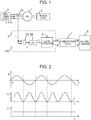
- the electric motor drive system shown in Fig 1 is intended to operate with a three-phase AC electric motor 1 (hereinafter simply abbreviated as an electric motor 1) as a power source, and is comprised of a drive power supply 2 of the electric motor 1, and a machine device 3 with the electric motor 1 as power.
- the drive power supply 2 is constituted by a power converter such as an inverter.
- the machine device 3 is directed to industrial equipment such as fans, pumps, compressors, machine tools, etc., and apparatuses each using an electric motor, such as automobiles, railway vehicles, household appliances, etc.
- a monitoring apparatus 100 serves to monitor the operation of this system or the AC electric motor included in the system and detect aging and a malfunction, or the sign of an abnormal operation.
- the monitoring apparatus 100 is installed in the existing electric motor drive system as post installed one.
- a phase current of the electric motor 1 detected by a current sensor 4a is processed by a monitoring device 5 from which data is transmitted to an analysis/diagnosis device 8 via a communication means 7.
- the current sensor 4a serves as a current detecting means and detects the phase current of the electric motor 1.
- the phase current detected by the current detecting means is assumed to be a current detection value.
- the communication means 7 is constituted of a wired or wireless communication network.
- the monitoring apparatus 100 of the present embodiment will next be described.
- the phase current (which is a U-phase current but may be any phase in Fig. 1 ) detected by the current sensor 4a being the current detecting means is read into the monitoring device 5 provided in the monitoring apparatus 100, and converted to a DC amount.
- the monitoring device 5 is intended to be realized by a microcomputer or FPGA, and actually read via an A/D converter (the AD converter is omitted in Fig. 1 ).
- a multiplier 55 and a low-pass filter (LPF) 56 are used to convert an AC amount to a DC amount.
- the detected phase current Iu is squared by the multiplier 55, and then only a DC component I1 is extracted by the low-pass filter 56.
- Fig. 2 illustrates the waveforms of respective signals.
- a feature extractor 6 extracts the magnitude of I1, a pulsating component contained in I1, and a transient fluctuation component thereof and thereby outputs a feature amount.
- the feature amount indicates e.g., aging, and a value or change indicative of an abnormal operation. Further, the feature extractor 6 outputs, for example, at least one feature amount of the AC electric motor, the drive power supply, and the machine device. Then, the feature extractor 6 sends the feature amount to the analysis/diagnosis device 8 via the communication means 7.
- the details of the feature extractor 6 will be described in detail in seventh to eleventh embodiments.
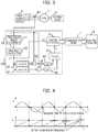
- FIG. 3 shows a monitoring device 5A introduced instead of the monitoring device 5 in Fig. 1 .
- Fig. 3 shows a monitoring device 5A introduced instead of the monitoring device 5 in Fig. 1 .
- those identical in part numbers to those in Fig. 1 are identical to those in Fig. 1 .
- the monitoring device 5A measures a half cycle of the phase current Iu being the current detection value and determines the AC frequency of the alternating current.
- a zero-cross period of the phase current is measured by using a timer of the microcomputer, and its value is assumed to be Tz.
- a frequency calculator 52 uses this measured time Tz to calculate the AC frequency (angular frequency) ⁇ 1.
- an SIN wave generator 53 and a COS wave generator 54 calculate sin ( ⁇ 1 t) and cos ( ⁇ 1 t), and multipliers 55 are used to multiply them and the phase current waveform Iu with each other. Since an average value of the multiplication result of these becomes a value corresponding to a sin component and a cos component included in Iu, a sin component (x) and a cos component (y) can be extracted through low pass filters (LPF) 56.
- LPF low pass filters
- an AC absolute value calculator 57 calculates the magnitude (amplitude) I1 of the phase current Iu.
- the feature extractor 6 uses these I1 and ⁇ 1, the behavior of the electric motor drive system is monitored.
- the feature extractor 6 extracts the pulsating component and transient fluctuation component contained in I1 and ⁇ 1 and thereby outputs a feature amount. Then, as with the first embodiment, the feature extractor 6 sends the feature amount to the analysis/diagnosis device 8 through the communication means 7.
- the present invention it is possible to convert the alternating current of the electric motor drive system into the amplitude and AC frequency of the current and monitor the same. Further, an observation period thereof can be shortened than when monitoring by the conventional power spectrum, and state monitoring including transient phenomena is made possible.
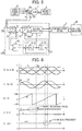
- FIG. 5 shows a case in which a W-phase current sensor 4b being a current detecting means is added to the configuration diagram of the second embodiment of Fig. 3 , and further a monitoring device 5B is introduced instead of the monitoring device 5A.
- a W-phase current sensor 4b being a current detecting means
- a monitoring device 5B is introduced instead of the monitoring device 5A.
- the AC amount being the current detection value has been converted into the DC amount only by the current sensor of one phase.
- the monitoring device 5B detects two phases of motor currents of three phases and converts an alternating current being a current detection value into a DC amount. Consequently, it is possible to convert the alternating current to the DC current from instant to instant values without waiting for the calculation of the average value of a current waveform, and a zero cross signal. The detection of a shorter fluctuation component than the period of the alternating current is also possible.
- the monitoring device 5B is comprised of a ⁇ converter 9 which converts a three-phase alternating current into alternating currents of orthogonal two phases, an arctangent calculator 10 which calculates, based on the two-phase alternating currents I ⁇ and I ⁇ calculated by the ⁇ converter 9, its alternating current phase angle ⁇ i*, a phase calculator 11 which calculates a coordinate conversion phase ⁇ i relative to ⁇ i*, a rotating coordinate converter 12 which coordinate-converts I ⁇ and I ⁇ into Ir and Ii being biaxial DC amounts on the basis of an output ⁇ i of the phase calculator 11, and a feature extractor 6B which inputs therein Ir and Ii converted into the DC amounts, and an angular frequency ⁇ rs being an internal amount of the phase calculator 11 to calculate a feature amount used in state monitoring.
- a ⁇ converter 9 which converts a three-phase alternating current into alternating currents of orthogonal two phases
- an arctangent calculator 10 which calculates, based on the two-phase alternating
- the phase calculator 11 is comprised of an adder 111 (where subtraction is performed) which calculates a deviation between the alternating current phase angle ⁇ i* and the coordinate conversion phase ⁇ i being the output of the phase calculator 11, a PLL controller 112 which performs PI control (proportional integral control) on the deviation and outputs the angular frequency ⁇ rs, and an integrator 113 which integrates ⁇ rs being the output of the PLL controller 112 to calculate the coordinate conversion phase ⁇ i.
- an adder 111 which calculates a deviation between the alternating current phase angle ⁇ i* and the coordinate conversion phase ⁇ i being the output of the phase calculator 11
- PI control proportional integral control
- the ⁇ converter 9 Based on Iu and Iw detected by the two-phase current sensors 4a and 4b, the ⁇ converter 9 converts them into two-phase alternating currents I ⁇ and I ⁇ orthogonal to each other.
- An ⁇ axis is the coordinates orthogonal to each other.
- the current phase ⁇ i* can be instantaneously calculated from values on the coordinates.
- ⁇ i ⁇ tan ⁇ 1 I ⁇ I ⁇
- the resulting ⁇ i* is an instantaneous value of a current phase.
- the rotating coordinate conversion can also be performed using this value, but in the present embodiment, the coordinate conversion phase ⁇ i is calculated through the phase calculator 11. The reason for this is as described below.
- phase calculator 11 Since a current ripple and noise are contained in the phase current, there is a possibility that when it is applied to the rotating coordinate conversion as it is, a large amount of ripples or noise are contained even in the converted DC amount. Therefore, the phase calculator 11 is introduced while also serving as the purpose of reducing noise and the purpose of calculating the frequency of the alternating current.
- the phase calculator 11 configures a control loop based on PLL control to thereby simultaneously perform the removal of noise and the frequency calculation of the alternating current.
- the PLL controller 112 outputs the angular frequency ⁇ rs such that the coordinate conversion phase ⁇ i being the output of the integrator 113 and the current phase ⁇ i* coincide with each other. If ⁇ i and ⁇ i* coincide with each other, the output ⁇ rs of the PLL controller 112 also coincides with the angular frequency of the alternating current, thus making it possible to obtain frequency information as well. Further, by setting the gain of the PLL controller 112, appropriate filtering is made, and the removal of noise is also possible.
- PI control proportional integral control
- KpPLL means proportional gain
- KiPLL means integral gain
- the rotating coordinate converter 12 converts I ⁇ and I ⁇ into DC amounts on the basis of the coordinate conversion phase ⁇ i obtained in the phase calculator 11.
- Ir I ⁇ ⁇ cos ⁇ i + I ⁇ ⁇ sin ⁇ i
- Ii ⁇ I ⁇ ⁇ sin ⁇ i + I ⁇ ⁇ cos ⁇ i
- the above Ir and Ii can be calculated for each calculation processing cycle of the monitoring device 5B. It is possible to capture a sudden change in current or the like at that moment.
- FIG. 6 An operation waveform example of the present monitoring device is shown in Fig. 6 .
- Fig. 6 (a) when the phase current waveform of the electric motor 1 gradually changes, it is difficult to detect this change while remaining at an AC amount. Especially when a sample of current is rough, processing after data acquisition takes a lot of time. Alternatively, it is extremely difficult to extract only the change amount from the AC waveform continuing to originally change, such as where there is a periodicity in the change of the amplitude.
- a three-phase AC is converted into two-phase alternating currents I ⁇ and I ⁇ ( Fig. 6(b) ).
- the phase calculator 11 calculates a coordinate conversion phase ⁇ i ( Fig. 6(c) ).
- minute phase variations of the alternating current can also be detected. It can be detected as a change in the angular frequency ⁇ rs shown in Fig. 6(e) .
- a change in current amplitude can also be captured as a change in the DC value as shown in the Fig. 6(d) .
- the analysis/diagnosis device 8 saves these feature amounts as time-series data and diagnoses a temporal change in the electric motor drive system. Since the conversion to a previously easy-to-analyze state amount is made in the monitoring device 5B, it is also easy to apply a diagnostic algorithm.
- the present invention in terms of the monitoring of the alternating current of the electric motor drive system, it is possible to convert the instantaneous current detection value to the amplitude and frequency, and the state monitoring including the transient phenomena can be realized.
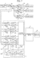
- Fig. 7 shows a block configuration diagram of the fourth embodiment.
- the configuration of the electric motor drive system is characteristic.
- a plurality of (n) electric motors 1a to 1n and a plurality of machine devices 3a to 3n are connected in parallel to a single drive power supply 2.
- an induction electric motor is used as an electric motor, such a configuration is possible.
- This is a configuration used in driving of transporting rollers of a rolling line in the steel industry, and a drive motor of a railway vehicle system, etc.
- the drive power supply 2 supplies power with a plurality of electric motors being regarded as a single electric motor.
- the loads on the electric motors are also different. There is a possibility that troubles such as a case in which a load is concentrated on a specific electric motor or machine device to remarkably wear only the machine, etc. will occur.
- the present embodiment provides a state monitoring method of a system in which a plurality of electric motors are connected to a single drive power supply.
- Fig. 7 shows that two current sensors corresponding to n numbers are added to n number of electric motors respectively, and a monitoring device 5C converts an alternating current of each electric motor into a DC amount and monitors the same. That is, a plurality of AC electric motors are driven by one drive power supply, and current sensors each being a current detecting means are provided in the respective AC electric motors.
- a plurality of AC electric motors are driven by one drive power supply, and current sensors each being a current detecting means are provided in the respective AC electric motors.
- those identical in part number to those shown in Fig. 3 or Fig. 5 are the same as those.
- Output currents (currents corresponding to all electric motors) of the drive power supply 2 are detected by the current sensors 4a and 4b, and ⁇ conversion and a phase calculation are carried out based on their current values.
- This operation is exactly the same as the operation of the monitoring device 5B in the second embodiment.
- the current values of all the electric motors are set to be 1/n times at gains 13a and 13b to calculate Ir and Ii as an average value of the number of the electric motors.
- U-phase and W-phase current sensors 4aa to n and 4ba to n are connected to the n electric motors. Their currents are ⁇ converted by ⁇ converters 9a to n and further converted into DC amounts Ira to Irn and Iia to Iin by rotating coordinate converters 12a to 12n respectively.
- a coordinate conversion phase ⁇ i and an angular frequency ⁇ rs are calculated from the value of the total current supplied from the drive power supply 2.
- the rotational coordinate conversion of the current of each electric motor is calculated in a common phase ⁇ i. That is, by outputting the feature amount on the basis of at least one of the amplitude, phase and frequency contained in the DC amount, the difference between the operating states of the individual electric motors can be clearly detected.
- Fig. 8 shows operation waveforms of the present embodiment. Variation in current value of each motor can be captured as a DC amount with respect to Ir and Ii being an average current. For example, from the currents in Fig. 8 (b) , it can be seen that the current Iia of the electric motor 1a is generated in negative form. From this point of view, only the electric motor 1a is seen to have been driven by a delayed phase current than the average value. Similarly, it can be seen that the electric motor 1b and the electric motor 1n assume a leading phase. It is understood from this waveform that there is a possibility that only the electric motor 1a is being driven under operating conditions different from others, and some sort of abnormality occur.
- the introduction of the monitoring device 5C makes it possible to facilitate feature extraction for detecting an abnormality and to considerably reduce the amount of data required for monitoring as well.
- the embodiment has shown the example of placing two by two the current sensors in the electric motors, but the method using one current sensor such as shown in the first embodiment is also applicable if only monitoring of steady operation is taken. Further, the current sensors 4a and 4b detecting the total current of the drive power supply 2, are removed, and instead the values obtained from the current sensors of the individual electric motors are added together to also enable its result to be taken as information of the total current.
- Fig. 9 shows a block configuration diagram of the fifth embodiment.
- Fig. 9 shows a feature that in the configuration diagram of the third embodiment shown in Fig. 5 , a rotation shaft sensor 14 is mounted to the rotating shaft of the electric motor 1. Based on a signal detected by the rotation shaft sensor, electric motor control is performed by a drive power supply 2D. Further, as a monitoring device, a monitoring device 5D is introduced instead of the monitoring device 5B of Fig. 5 . Incidentally, in parts in Fig. 9 , those identical in part number to those in Figs. 3 to 7 are the same as those. In the present embodiment, the rotation shaft sensor is used as a rotation shaft measuring means, but is not limited thereto.
- the current sensor is added to the existing electric motor drive system to monitor the electric motor drive system using only its current detection value.
- the rotation shaft sensor of the electric motor 1 is connected as shown in Figure 9 , depending on the system. Further, depending on conditions, it may be possible to retrieve the signal of the rotation shaft sensor.
- the configuration of the present embodiment resides in that targeting such an electric motor drive system, the detected current is converted into a DC amount by utilizing the existing rotation shaft sensor.
- the rotation shaft sensor 14 is connected to the rotating shaft of the electric motor 1, and is a pulse encoder which outputs pulse signals of A, B and z phases in accordance with the rotation of the electric motor 1.
- the pulse encoder is a speed sensor generally used in an AC servo system or the like. It is possible to generate a position (angle) signal by integrating an output pulse train. To perform a home position alignment of a mechanical angle, a z phase to generate one pulse in one rotation is also assumed to be output.
- a feature part of the present embodiment is that the pulse signals are diverted in the monitoring device 5D to utilize the same for the coordinate transformation of the detected AC current.
- a speed/position detector 15 counts the numbers of pulses of the A and B phases to thereby calculate the rotational speed of the electric motor 1 and further integrates the pulse train to thereby calculate a phase ⁇ d of the rotation shaft. Since this ⁇ d is linked with the alternating current phase of the electric motor 1, the current on the ⁇ -axis can be converted into a DC amount if rotating coordinate conversion is performed based on ⁇ d. Further, if resetting of the phase angle is done based on the z-phase signal, the coordinates of the dq-axis of the electric motor 1 are obtained, whereby phase information of the inside of the drive power supply 2D can be obtained.
- a calculation is performed in the same manner as (Numeral 5) and (Numeral 6) based on the phase ⁇ d to convert the current into a DC amount.
- a d-axis current and a q-axis current used for vector control of the AC electric motor can be calculated. Since the generated torque of the electric motor 1 is proportional to the q-axis current, it is possible to monitor the generated torque of the electric motor 1 by monitoring Iq.
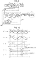
- Fig. 10 shows observed waveforms when the present embodiment is used. Changes in the current and a change in the rotational speed can be observed as with the waveform example of Fig. 4 .
- the current is converted into the DC amount on the basis of the phase of the current itself, whereas in the present embodiment, the conversion based on the information of the rotation shaft sensor is performed, and hence more precise movement of current can be captured.
- ⁇ rs is a signal obtained from the actual rotation shaft sensor, the rotational speed itself is eventually detected. It is thus possible to realize more accurate monitoring.
- Fig. 11 shows a block configuration diagram of the sixth embodiment.
- Fig. 11 shows a feature that voltage sensors 16a and 16b each detecting an inter-line voltage of an electric motor 1 are attached to the configuration diagram of the third embodiment shown in Fig. 5 .
- the voltage sensors serve to detect inter-line voltages Vuv and Vvw and thereby to help monitoring of the electric motor drive system.
- a monitoring device 5E is introduced instead of the monitoring device 5B of Fig. 5 .
- the voltage sensor is used as a voltage detecting means, but is not limited thereto.
- the monitoring device 5E in Fig. 11 inputs the inter-line voltage Vuv, and Vvw therein, and converts the three-phase voltage into biphasic V ⁇ and V ⁇ at an ⁇ converter 9E.
- An arctangent calculator 10E calculates a voltage phase ⁇ v* on the basis of the equation (V ⁇ is used instead of I ⁇ , and V ⁇ is used instead of I ⁇ ) shown in the (Numeral 3).
- a phase calculator 11 is operated to control a coordinate conversion phase ⁇ v, so as to follow a voltage phase ⁇ v*.
- a rotating coordinate converter 12E converts I ⁇ and I ⁇ into DC amounts according to the phase of ⁇ v.
- Fig. 12 shows an example of current and voltage waveforms of the electric motor 1, and waveforms of an active current I ⁇ and a reactive current Iz obtained by the monitoring device 5E.
- the phase of the AC current waveform changes in the middle of the Figure, but the absolute value itself of the current has no change. Also, the frequency does not change either except during transition.
- the monitoring device 5E is capable of capturing that the current phase clearly changes by observing the current as the active current and the reactive current, and an increase in the active current, i.e., power consumption is also increased.
- Fig. 13 shows that in the configuration diagram of the fifth embodiment shown in Fig. 9 , without using the rotation shaft sensor of the electric motor 1, phase information ⁇ d used inside a drive power supply 2F is drawn to the outside instead, and a monitoring device 5F converts an alternating current into a direct current on the basis of the phase information ⁇ d to perform state monitoring of the electric motor drive system.
- the drive power supply 2F is an inverter for controlling the electric motor 1 and is comprised thereinside of a main circuit power supplier 21 which supplies power to an inverter main circuit unit, a main circuit 22 of the inverter which applies an arbitrary AC voltage to the electric motor 1, a current sensor 23 which detects an AC output current of the main circuit 22, and a controller 24 which controls the inverter main circuit unit 22 based on a current detection value obtained by the current sensor 23.
- the controller 24 calculates the phase information ⁇ d being an internal phase for vector control of the electric motor 1.
- the rotation shaft sensor of the electric motor 1 is not attached, and the estimation calculation of a rotation shaft position (angle) is performed inside the controller 24 to calculate ⁇ d.
- the monitoring device 5F receives the phase information ⁇ d being an internal value of the drive power supply 2F and coordinate-converts the alternating current in the same manner as
- a PLL controller may be newly introduced, or a differential operation unit 25 may be introduced as shown in Fig. 13 to calculate the angular frequency by differential operation.
- the state monitoring similar to that in the fifth embodiment can be realized without using the rotation shaft sensor.
- a monitoring device according to an eighth embodiment of the present invention will be described using Figs. 14 and 15 .
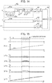
- Fig. 14 shows a block configuration diagram of a feature extractor 6G usable in the monitoring devices 5 and 5B to 5F described so far.
- the eighth embodiment can be realized by using the feature extractor 6G for the feature extractor according to each of other embodiments.
- the feature extractor 6G of the present embodiment provides a function of extracting a vibration component from alternating currents Ir and Ii each converted into a DC amount, or from an angular frequency ⁇ rs.
- the feature extractor 6G of Fig. 14 is comprised of vibration component extractors 61a and 61b which extract vibration components included in the currents Ir and Ii each converted to the direct current, sample switches 62 each of which samples data, and a memory 63 which stores the data.
- the vibration component extractor 61a is comprised of a first-order lag filter 31a of a time constant Th, an adder 111, an absolute value calculator 32, and a first-order lag filter 31b of a time constant Tj.
- the current Ir which has been converted into the DC amount is assumed to include vibration such as shown in Fig. 14(a) .
- vibration often occurs where, for example, a drive frequency of an electric motor 1 and a mechanical resonance frequency of a machine device 2 match each other. Therefore, there occur such phenomena that when the electric motor 1 is accelerating, vibration is generated when the drive frequency is approaching the mechanical resonance frequency, and vibration is suppressed again when exceeding the region of its rotational speed. If these vibration phenomena and an AC frequency at which they occur are associated with each other, an abnormality of the machine device and its changes with time can be detected, thereby making it possible to help state monitoring.
- a current value through the first-order lag filter of the time constant Th (as this current value, the average value at which the vibration component is canceled is output) is subtracted from the original Ir (the adder 111 being used as a subtractor in Fig. 14 ) to thereby extract only the vibration component (a waveform of 'A' shown in Fig. 15(c) ).
- the absolute value of the signal 'A' is determined by the absolute value calculator 32 to obtain a waveform of 'B' shown in Fig. 15(d) .
- 'B' is a waveform like a full-wave rectification, it further passes through the first-order lag filter 31b of the time constant tj to output only a DC component (a waveform 'C' in Fig. 15(e) ). That is, when vibration occurs in the direct current Ir, the vibration component is output as the value of the DC amount from the vibration component extractor 61a.
- the waveform is sampled at predetermined intervals and stored in the memory 63. It is possible to extract a vibration component by performing the same processing even on the DC amount Ii. In any case, as compared to analyzing the alternating current waveform while remaining in the AC amount, the conversion of the AC amount into the DC amount enables a vibration component to be extracted by a simple algorithm.
- the correlation between the drive frequency and the vibration component can be stored as data. By analyzing the correlation, it can be utilized as a feature amount for determining a variation in a resonance point of the machine device, i.e., the wear and deterioration of the device.
- the feature extractor As described above, by using the feature extractor according to the present embodiment, it is possible to extract the vibration component in the simple algorithm, and it is possible to help state monitoring of the electric motor drive system.
- a monitoring device according to a ninth embodiment of the present invention will be described using Fig. 16 .
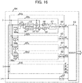
- Fig. 16 shows a block configuration diagram of a feature extractor 6H usable in the monitoring devices 5 and 5B to 5F described so far.
- the ninth embodiment can be realized by using the feature extractor 6H for the feature extractor according to each of other embodiments.
- the feature extractor 6H of the present embodiment provides a function of specifying and extracting alternating currents Ir and Ii each converted into a DC amount, or pulsating components contained in an angular frequency detection value, up to the frequency.
- the feature extractor 6H is comprised of pulsating component analyzers 64a and 64b which perform component analysis corresponding to the order of the frequency with respect to Ir and Ii each converted into the DC amount, and a memory 63 which stores a result of its analysis. Further, the pulsating component analyzers 64a and 64b are respectively comprised of frequency analyzers 65a to 65d, constant setters 66a to 65d, and sample switches 62.
- the frequency analyzers 65a to 65d As operations of the frequency analyzers 65a to 65d, those quite equal to the calculation algorithm for the current amplitude I1 in the first embodiment are used. However, the angular frequency ⁇ input to the SIN wave generator 53 and the COS generator 54 is given by multiplying ⁇ rs by constants (1, 2, 6, 0.5) set by the constant setters 66a to 66d respectively.
- the frequency analyzer 65a performs extraction of the pulsating component of ⁇ rs (i.e. the primary component of ⁇ rs). Its calculation result Ir1 is sampled by the sample switch 62 and stored in the memory 63.
- the frequency analyzer 65b, the frequency analyzer 65c, and the frequency analyzer 65d can extract a secondary component of ⁇ rs, a 6-order component thereof, and a 1/2-order component thereof respectively.
- the primary, secondary, sixth-order, and 0.5-order pulsating components can be extracted with respect to the drive frequency.
- These pulsation factors can be considered as follows.
- the primary component of the drive frequency is apt to occur when the offset current (DC component) of the drive power supply (inverter) occurs, and the abnormality of the drive power supply is estimated. Further, the secondary component is likely to occur when a three-phase imbalance has occurred. It occurs even such as where the electric motor is demagnetized by heating. As for the sixth-order pulsation, spatial harmonics of the electric motor, cogging torque, or strain of the inverter, or the like may be a factor. Further, when the number of poles of the electric motor is four, a load fluctuation for each revolution occurs as a 1/2-order pulsating component.
- the first-order component of a rotation frequency (1/2-order pulsating component of an electrical angular frequency if a four-pole machine is taken) is generated.
- a rotation frequency 1/2-order pulsating component of an electrical angular frequency if a four-pole machine is taken
- a monitoring device according to a tenth embodiment of the present invention will be described using Figs. 17 and 18 .
- Fig. 17 shows a block configuration diagram of a feature extractor 6J usable in the monitoring devices 5 and 5B to 5F described so far.
- the feature extractor 6J of the present embodiment captures transient phenomena when alternating currents Ir and Ii each converted into a DC amount vary beyond a preset threshold value (predetermined range), and stores time-series data before and after it.
- the transient phenomenon of the current Ir or Ii converted to the DC amount is captured, and a varying waveform before and after it is saved, thereby helping state monitoring.
- the feature extractor 6J shown in Fig. 17 is comprised of a trigger signal generator 67 which observes an amount of change in the current Ir converted into the DC amount and generates a trigger signal where it exceeds IR0 being a change amount set in advance, i.e., where it exceeds a predetermined range, sample value, sample value storing units 68a to 68c each of which stores values up to the previous n samples with respect to the currents Ir and Ii and angular frequency ⁇ rs, and a memory 63.
- a trigger signal generator 67 which observes an amount of change in the current Ir converted into the DC amount and generates a trigger signal where it exceeds IR0 being a change amount set in advance, i.e., where it exceeds a predetermined range
- sample value sample value storing units 68a to 68c each of which stores values up to the previous n samples with respect to the currents Ir and Ii and angular frequency ⁇ rs, and a memory 63.
- the amount of change in the current Ir is calculated by a first-order lag filter 31c and an adder 111 (operated as a subtractor in this case), and the amount of its change is compared with IR0 being a preset reference value in a comparator 33.
- IR0 is set at a constant setter 66e.
- the output of the comparator 33 becomes '1'.
- the trigger signal is output via a delay circuit 34 with a delay of a delay time Tx.
- the sample value storage units 68a to 68c sequentially store the past sample values by one sample delay elements 69 (1/z), and store internal values up to past n samples.
- sample switches 62 With the input of the trigger signal to the sample value storage unit, sample switches 62 simultaneously perform sampling, and n pieces of data are stored into the memory 63.
- a behavior waveform with the fluctuation in Ir as a trigger is stored in the memory 63.
- Fig. 18 shows the operation waveforms of the present embodiment.
- the waveforms show an example when the current waveform of Ir changes rapidly due to a load fluctuation or the like.
- the output of the comparator 33 becomes '1'.
- a trigger is given to the sample value storage units 68a to 68c.
- N pieces of data of Ir, Ii, and ⁇ rs being the past data at the transition are stored in the memory 63 as shown in Fig. 18(e), (f), and (g) .
- the transient phenomenon of the electric motor is an important factor relating to the control response. For example, when the electric motor constant is changed by temperature or the like, there is a high possibility that it can be observed as a difference in transient phenomenon. Thus, the relationship of transition between these currents and the drive frequency is stored as data and can be made useful in the analysis.
- the amount of variation to be used for analysis includes the amount of variation in the DC amount, or the amount of change in frequency used in converting the current detection value to the DC amount.
- Fig. 19 the configuration of storing changes in the currents Ir and Ii with the time when the angular frequency ⁇ rs fluctuates beyond the threshold value (predetermined range) as a trigger.
- a feature extractor 6K and a trigger generator 67K are substantially the same as the embodiment of Fig. 17 , but different in that the factor of trigger occurrence is ⁇ rs.
- an angular frequency ⁇ rs0 is set by a constant setter 66f.
- the amount of variation used for the analysis in this case includes the amount of change in the frequency, or the amount of change in the DC amount.
- Fig. 20 shows a block configuration diagram of the eleventh embodiment.
- Fig. 20 shows a feature that in the configuration diagram of the third embodiment shown in Fig. 5 , a vibration sensor 35 is attached to an electric motor 1.
- a vibration acceleration fx detected by this vibration sensor is read into a monitoring device 5L, and a feature amount is extracted by a feature extractor 6L.
- Other parts are the same as those of Fig. 5 in the third embodiment.
- Fig. 21 shows the configuration of the feature extractor 6L.
- the feature extractor 6L show substantially the same configuration as that of the feature extractor 6G of the seventh embodiment shown in Fig. 14 .
- a vibration component extractor 61c which receives the vibration acceleration fx, and a sample switch 62 for its output are added. With this configuration, it is also possible to extract a vibration component contained in fx in addition to the vibrations of currents Ir and Ii.
- Fig. 22 shows the waveforms of the Ir, angular frequency ⁇ rs, and vibration acceleration fx.
- the correlation between the information of the external sensor and the DC amount is analyzed, and the feature amount is extracted, thereby making it possible to separate vibration factors and help state monitoring.
- the vibration sensor may be attached to the machine device, for example.
- a three-dimensional acceleration sensor may be used.
- the external sensor instead of the vibration sensor, a noise sensor (microphone), a temperature sensor, or a humidity sensor may be used.
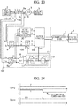
- Fig. 23 shows a block configuration diagram of the twelfth embodiment.
- Fig. 23 illustrates a configuration in which in the configuration of the sixth embodiment shown in Fig. 11 , a monitoring device 5M is introduced instead of the monitoring device 5E.
- the monitoring device 5M has a configuration in which an active/reactive power calculator 36 is newly added, and calculates active power P and reactive power Q and inputs their calculated values to a feature extractor 6M.
- the voltage information of the drive power supply 2 is utilized based on the inter-line voltage information, and the alternating current of the electric motor is monitored by being separated into the active current component and the reactive current component. In the present embodiment, it is further monitored by being converted into the active power P and the reactive power Q.
- the active/reactive power calculator 36 performs the following operations using the current and voltage on a ⁇ -axis.
- the feature extractor 6M uses at least one of the active power P and the reactive power Q calculated from the above equations to extract a feature amount such as aging, an abnormal operation or the like. Then, the monitoring of states of the electric motor drive system and the AC electric motor is performed.
- Sine the active power P means that the power consumption of the system is calculated instantly, it is possible to monitor the amount of power consumption of the system. Further, since it is possible to monitor how the amount of power consumption changes by stacking the number of years, it can help maintenance of the machine device.
- Fig. 24 shows an example of monitored waveforms of the active power P and the reactive power Q.
- the reactive power suddenly changes in the middle, and the angular frequency ⁇ rs and active power P are not changed. It can be seen that when such a phenomenon is assumed to have occurred, the power consumption required for the machine device 3 remains unchanged, and only the reactive power increases (increases in the negative direction).
- the original power supply voltage of the drive power supply 2 is lowered, the magnitude of the voltage applicable to the electric motor 1 is reduced, so that the electric motor 1 is performing a weakening field operation. That is, it becomes possible to determine even abnormality of the drive power supply 2.
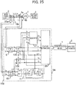
- Fig. 25 shows a block configuration diagram of the thirteenth embodiment.
- Fig. 25 shows a configuration in which in the configuration of the sixth embodiment shown in Fig. 11 , a monitoring device 5N is introduced instead of the monitoring device 5E.
- the monitoring device 5N is added with a rotating coordinate converter 12E which coordinate-converts V ⁇ and V ⁇ at a phase angle ⁇ v, and a state observer 37 at which voltages Va and Vz on the rotating coordinates are computed and which further observes an internal state amount of the electric motor 1.
- the state observer 37 observes a state amount of the system which is not detected directly, by estimating and calculating the same, thereby helping monitoring.
- the estimation calculation of generated torque Tm of the electric motor 1 and load torque TL thereof each being the state amount of the system is performed on the basis of a mathematical model of the electric motor 1 and a mathematical model of the machine device 2.
- a feature extractor 6N inputs therein Ia, Iz, Va, Vz, ⁇ rs, etc. in addition to the output of the state observer 37 and performs state monitoring at the time of steady-state and transition.
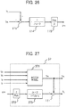
- Fig. 26 shows a physical model representing the relationship between the motor torque Tm, the load torque TL, and the angular frequency ⁇ rs in a block diagram.
- the rotational speed of a mechanical angle is obtained by the difference between the torque Tm generated by the electric motor 1 and the load torque TL generated by the machine device 3, inertia J of a mechanical system including an electric motor, and a damping coefficient D. Further, by multiplying it by the number of pole pairs Pole/2 of the electric motor 1, the electrical angular frequency ⁇ rs of the electric motor 1 can be obtained.
- the state observer 37 calculates back the load torque TL.
- Fig. 27 shows a block configuration of the state observer 37.
- a motor model 371 being a mathematical model of the electric motor 1 determines the generated torque Tm of the electric motor 1 by calculation.
- an inverse model of the physical model to obtain the angular frequency ⁇ rs shown in Fig. 26 is implemented by a gain 372 (the inverse of the number of pole pairs) and an imperfect differentiator 373 (inverse model of the machine device) to calculate the load torque TL.
- a time constant Tobs of denominator in the imperfect differentiator 373 is observer gain. It is possible to adjust the band of a frequency component included in TL by this time constant.
- the generated torque Tm of the electric motor 1 and the load torque TL which are difficult to be detected directly can be determined using a mathematical model.
- the torque vibration of the machine device, etc. can also be observed by the state observer 37. This can help state monitoring.
- the feature extractor 6N may perform processing such as the vibration component extraction, output, etc. which have been described thus far.
- the various state amounts can be calculated by introducing a physical model as a more detailed mathematical model. This is available even for monitoring of the vibration of a vehicle body, the effectiveness of a suspension, or a road surface state, etc. by simulating the body of an automobile, for example.
- the new state amounts such as the generated torque, the load torque, etc. can be determined by calculation, thus making it possible to help state monitoring.
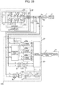
- Fig. 28 shows a block configuration diagram of the fourteenth embodiment.
- Fig. 28 illustrates a configuration in which in the configuration of the sixth embodiment shown in Fig. 11 , the details of a drive power supply 2 are described, and a monitoring device 5P is introduced instead of the monitoring device 5E.
- the previous embodiments have been constructed mainly for the purpose of the state monitoring of the electric motor 1 and the machine device 3.
- the present embodiment is intended to monitor operating states of switching elements (T1 to T6 and D1 to D6) constituting an inverter main circuit.
- the drive power supply 2P is comprised of a DC voltage source 21 of a voltage VDC, a three-phase full-bridge inverter main circuit unit 221, a gate driver 222 to give a gate signal to each switching element, a current sensor 23, and a controller 24.
- the monitoring device 5P has a function of separating an alternating current to an active current and a reactive current, based on a voltage sensor as with the embodiment of Fig. 11 . Further, the monitoring device 5P monitors the operating state of each switching element of the inverter main circuit unit 221. Functions newly added from the monitoring device 5E are as follows.
- the monitoring device 5P is constituted of an adder 111 (operated as a subtractor here) which calculates a V-phase current from U-phase and W-phase currents, a conduction ratio converter 38 which converts an inter-line voltage to a conduction ratio (duty), current allocators 39a to 39c which assign the phase currents to the respective switching elements, and a feature extractor 6P which converts the outputs of these current allocators into feature amounts.
- an adder 111 (operated as a subtractor here) which calculates a V-phase current from U-phase and W-phase currents
- a conduction ratio converter 38 which converts an inter-line voltage to a conduction ratio (duty)
- current allocators 39a to 39c which assign the phase currents to the respective switching elements
- a feature extractor 6P which converts the outputs of these current allocators into feature amounts.
- the monitoring device 5P determines by calculation how much current flows to any of the switching elements of the inverter main circuit unit 221 to thereby monitor the power balance and monitor whether or not current concentration occurs.
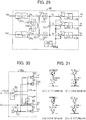
- Fig. 29 shows an internal configuration of the conduction ratio converter 38. Since the inter-line voltages Vuv and Vvw are pulse voltages, pulse components thereof are removed by first-order lag filters of time constant Tfc and then they are converted to phase voltages. In Fig. 29 , the calculation of (Numeral 7) through (Numeral 9) is performed using gains 116 and 117 and adders 111.
- Duty ratios Du to Dw are calculated by adding the value of 1/2 of the DC power supply to the resulting phase voltages Vu, Vv and Vw (performing setting by a constant setter 66g) and multiplying them by gains 119 (performing setting to 1/VDC). Consequently, Du to Dw varies in a range of 0.0 to 1.0. Incidentally, as in the seventh embodiment ( Fig. 13 ), if it is possible to directly obtain the duty ratios Du to Dw from the controller 24, the conduction ratio converter 38 may be omitted.
- the respective current allocators 39a to 39c are equivalent to the arms of the respective phases of the inverter main circuit unit 221. If the U phase is taken, conduction currents of IGBT T1 and T4 and reflux diodes D1 and D4 are calculated.
- the polarity of the phase current Iu is determined by a switch 70. If it is 'positive', the switch is changed to a p side, and if it is 'negative', the switch is changed to an n side. If the current is 'positive', there are two types where, as shown in Figs. 30(a) and (b) , T1 being the upper IGBT is turned on, and the lower diode D4 is turned on. The proportion of current between T1 and D4 is determined by the duty Du of switching of the U-phase. Since the ratio at which T1 is turned on is proportional to Du, Iu and Du are multiplied by a multiplier 55 and its result is output as a current value IT1 of T1. Since a current of D4 is the remaining proportion of Du, 1-Du is determined by a constant setter 118 and the adder 111 (operated as a subtractor here), and Iu ⁇ (1-Du) is calculated by the multiplier 55 and output as ID4.
- phase current Iu is negative, as shown in Figs. 30(c) and (d) , either D1 or T4 is turned on, and Du and (1-Du) are respectively multiplied to calculate a current ratio.
- the polarity of the negative-side current is reversed using a gain 120.
- phase current can be assigned to each of the respective switching elements.
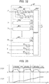
- Fig. 32 shows the configuration of the feature extractor 6P.
- device state monitoring units 40a to 40L are aligned and respectively calculate temperature-corresponding state amounts T_IT1 to 6 and T_ID1 to 6 and operation-history corresponding state amounts S_IT1 to 6 and S_ID1 to 6 of 12 pieces of switching elements.
- the configuration of the device state monitoring unit 40 is constituted of a first-order lag filter 31d of a time constant Tn, an integrator 113, and a sample switch 62.
- the first-order lag filter 31d is required to match the time constant with a temperature time constant of each switching element. By matching the time constant with the temperature time constant, the operating temperature of each device can be estimated and calculated. Also, viewed from another angle, it is possible to monitor whether an offset current flows in any device.
- the load characteristics of the machine device 3 often becomes three-phase balanced.
- a load fluctuation occurs in the same cycle as the rotation cycle, and hence a load current is likely to concentrate on the particular switching element.
- Such an offset state can be monitored by this feature extractor.
- the history of the device can be saved. By accumulating and analyzing history data, it is possible to help life prediction of the device.
- Fig. 33 shows an example of waveforms of the outputs T_IT1 and S_IT1 of the device state monitoring unit 40a. It can be seen that T_IT1 varies with the operation of the electric motor drive system. Further, it is possible to confirm a state of S_IT1 leaving a history by integrating an operating current.
- a monitoring device according to a fifteenth embodiment of the present invention will be described using Figs. 34 and 35 .
- Fig. 34 shows a block configuration diagram of the fifteenth embodiment.
- the present embodiment can be realized by replacing the feature extractor 6C of the fourth embodiment shown in Fig. 7 with a monitoring device 6Q shown in Fig. 34 .
- the drive currents of the plural (n) electric motors have been subjected to the rotating coordinate conversion in the same phase to monitor the operating states of the individual electric motors.
- the current of each electric motor is converted to extract a feature amount.
- the feature extractor 6Q is comprised of polar coordinate converters 71a to 71x each of which converts a current of a DC amount subjected to rotating coordinate conversion (transformation on the orthogonal coordinates of two axes) into polar coordinates, and a memory 63Q.
- the polar coordinate converters 71a to 71x are respectively constituted of an arc tangent calculator 10, an AC absolute value calculator 57, an adder 111, and a sample switch 62, which are the parts described so far.
- the currents of the respective electric motors are subjected to the rotating coordinate conversion based on the total current to obtain Ira to Irn and Iia to Iin respectively.
- the polar coordinate converter 71x computes, in terms of Ir and Ii being the average current, an angle ⁇ 1 formed by the two at the arc tangent calculator 10, calculates I1 being the magnitude at the AC absolute value calculator 57, samples its value by the sample switch 62, and saves the same into the memory 63Q.
- the feature part of the present embodiment is that the feature amount of the current of each electric motor is determined based on ⁇ 1 and I1 obtained with the average current.
- the differences between the average I1 and ⁇ 1 determined in the polar coordinate converter 71x and Ia to In and ⁇ a to ⁇ n calculated similarly by the respective electric motors are respectively calculated and stored in the memory 63P as dIa to dIn and d ⁇ a to d ⁇ n. Since dIa to dIn and d ⁇ a to d ⁇ n are amounts shifted from the average value, it is possible to monitor how much the current amplitude is shifted, or how much the phase difference is generated. That is, the operating state of each AC electric motor can be calculated based on at least one of the phase of the current flowing through the AC electric motor and the amplitude thereof.
- Fig. 35 shows a waveform example of these feature amounts.
- a drive frequency ⁇ rs is increased, the electric motor is in a state of being accelerated, and the average current amplitude I1 is increased slightly but does not change greatly.
- dIa is increased in proportion to the speed
- dIb has a constant deviation without depending on the speed.
- the electric motor 1a can determine that an error proportional to the rotational speed is being generated. That is, the operating state of each AC electric motor can be separately calculated.
- the error proportional to the rotational speed it is considered that in the case of an electric motor for a railway vehicle, a difference in wheel diameter occurs, and only the electric motor 1a is increasing in load with the rotational speed. Further, it is considered that an electric motor 1b having an almost constant error without depending on the load has a possibility that an error occurs in the constant.
- the electric motor drive system which drives the plurality of electric motors with one drive power supply is capable of separating the differences in operating state between the respective electric motors and outputting the feature amount. It is thus possible to help state monitoring.
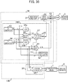
- the present embodiment resides in that in the configuration diagram of the seventh embodiment shown in Fig. 13 , the controller 24 is replaced with a controller 24R shown in Fig. 36 and further Id and Iq being internal state amounts of the controller 24R are drawn to the outside, and feature extraction is performed in a monitoring device 5R.
- the monitoring device 5R is comprised of a feature extractor 6R. Then, state monitoring is performed by a analysis/diagnosis device 8 through a communication means 7.
- a drive power supply 2R performs vector control of an electric motor 1, and the details of its operation are described in the controller 24R of Fig. 36 .
- the phase current of the electric motor 1 is detected by a current sensor 23 provided inside the drive power supply 2R and then converted into a DC amount using a phase angle ⁇ d at a dq coordinate converter 81.
- ⁇ d used for coordinate conversion is calculated in a speed/phase calculator 82.
- Fig. 36 shows the configuration of speed-position sensorless control not using the rotation shaft sensor in the electric motor 1, but there is no problem even if these sensors are used.
- the phase current of the electric motor 1 is converted into the currents Id and Iq on the d- and q-axes each being a DC amount, which are respectively used for vector control.
- the difference between the d-axis current Id and a d-axis current command Id* output from an Id* generator 83 is calculated by an adder 111, and controlled by a current controller (ACR) 85a such that the deviation therebetween becomes zero.
- the difference between the q-axis current Iq and a q-axis current command Iq* output from an Iq* generator 84 is calculated by an adder 111, and controlled by a current controller (ACR) 85b so that the deviation therebetween becomes zero.
- a motor model calculator 86 performs voltage operation by a mathematical model based on the constants of the electric motor 1, and adds its outputs to the outputs of the respective ACR 85a and 85b to calculate voltage commands Vd* and Vq* of the d and q axes.
- the voltage commands Vd* and Vq* are converted into three-phase AC voltages at a dq inverse converter 87, and then converted into a pulse train by a PWM (pulse width modulation) generator 88, thereby driving an inverter of a main circuit.
- the current controller executes control so that the deviation becomes zero on the rotating coordinate axes synchronized with the AC voltage output from the drive power supply.
- each of the Id* generator 83 and the Iq* generator 84 means a command generator in the upper order of the current controller.
- it is a block including a speed controller (ASR) or the like controlling the speed of the electric motor 1.
- ASR speed controller
- the drive power supply in the electric motor drive system often constitutes a vector control system as shown in Fig. 36 .
- the controller often performs control thereinside by converting the alternating current into the DC amount once.
- the present embodiment is characterized by diverting the coordinate conversion in the controller 24R and retrieving the DC amount after the conversion thereof to the outside.
- the controller 24R transmits the values of Id and Iq to the monitoring device 5R by performing serial or parallel communications, or conversion to an analog value, etc.
- the feature extractor 6R executes extraction of a feature amount with respect to the received Id and Iq.
- the reduction in the calculation load factor of the microcomputer enables the extraction of various feature amounts to be executed simultaneously.
- the algorithms of the feature extractors in Figs. 14 , 16 , 17 , 19 , etc., described thus far are processed in parallel to make it also possible to enhance monitoring. Further, even if the control internal state amount other than Id and Iq, e.g., ⁇ r or the like is drawn to the outside, no problem occurs.
- control internal state amount of the electric motor drive system is drawn to the outside, thereby making it possible to reduce the load of the monitoring device, and further achieve monitoring by conversion to the various feature amounts.
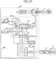
- the present embodiment resides in that in the configuration diagram of the sixteenth embodiment shown in Fig. 36 , the controller 24R is replaced by a controller 24S shown in Fig. 37 , the monitoring device 5R is eliminated, and instead a feature extractor 6S is installed inside the controller 24S.
- a feature part of the present embodiment resides in that the role of the monitoring device is included in a drive power supply 2S. Therefore, the output of the feature extractor 6S is transferred through a communication means 7 directly from the drive power supply 2S to an analysis/diagnosis device 8.
- the drive power supply 2S is provided thereinside with a monitoring function, i.e., the controller and the feature extractor 6S being a feature extracting means are operated on a signal processing device in which they are integrated, adverse effects to communications are eliminated, and more internal amounts can be utilized.
- the calculation load factor of the controller 24S increases, but if design such as using a recent multi-core microcomputer, sharing a bus in multiple microcomputers, etc. is performed, the implementation of such an algorithm is easy. Of course, it is necessary to take substantial review of a software structure for the existing device. However, the above is a very effective means when developing a drive power supply with a pre-monitoring function.
- the feature extractor outputs the feature amount on the basis of at least one of any DC amount and the rotational speed used in the controller. It is thus possible to realize the monitoring of the electric motor drive system.
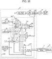
- the present embodiment resides in that in the configuration diagram of the seventeenth embodiment shown in Fig. 37 , the controller 24S is replaced by a controller 24T shown in Fig. 37 , and further constitutes position sensorless control not using the rotation shaft sensor with the electric motor 1 as a permanent magnet electric motor 1T.
- an axial error calculator 82T is introduced instead of the speed/position calculator 82 in Fig. 37 , and further adders 111, a PLL controller 112, and an integrator 113 are added. Moreover, the feature extractor 6S is changed to a feature extractor 6T.
- the controller 24T in Fig. 38 shows its example.
- the axial error calculator 82T the axial error occurring between the electric motor and the controller is calculated, and the adder 111 and the PLL controller 112 are used to calculate a drive frequency ⁇ r of the electric motor so that the value of the axial error becomes zero.
- the control internal phase ⁇ d is adjasted, thereby controlling the axial error ⁇ d to zero.
- the internal amount called the 'axial error ⁇ d' is a very important value, and the generated amount of this deviation is intended to determine the stability of the system.
- ⁇ d is controlled to zero, but at the time of a transient response, the time of occurrence of a constant error, etc., there is a case where a deviation occurs in ⁇ d. This is because, as its major factor, a response delay related to a control response occurs inevitably where a load change occurs (primarily, the operation related to setting gain of the PLL controller 112). If paradoxically grasped, it is possible to infer from the movement of ⁇ d at the load change, what kind of load change has occurred. Further, it is considered that even if there is no change in load itself, a change occurs in the movement of ⁇ d even where motor parameters and mechanical parameters change due to aging.
- the monitoring of ⁇ d is extremely important. If the feature extractor 6T performs the conversion thereof to the feature amount and its monitoring on the basis of the axial error, it is possible to quickly detect changes of the electric motor and the machine device, and the sign of abnormality.
- the feature extractor 6T carries out analysis of a variation component of the axial error ⁇ d and frequencies, etc. through the various algorithms described in the previous embodiments. That is, the feature extractor 6T outputs the feature amount on the basis of the axial error. It is thus possible to more quickly an abnormal state. Further, an important variable is obtained as a factor to perform analysis/diagnosis.
- the monitoring device in the electric motor drive system using the position sensorless permanent magnet electric motor, the monitoring device can be realized which is capable of improving detection accuracy with respect to aging, abnormal operations, or the sign of abnormality.
- the present embodiment resides in that in the configuration diagram of the seventeenth embodiment shown in Fig. 37 , the controller 24S is replaced by a controller 24U shown in Fig. 39 , and configures speed sensorless control not using the rotation shaft sensor with the electric motor 1 as an induction electric motor 1U.
- a speed calculator 82U is introduced instead of the speed/position calculator 82 in Fig. 37 , and further a slip frequency calculator 91 and a magnetic flux estimator 92 are added. Moreover, the feature extractor 6S is changed to a feature extractor 6U.
- the speed calculator 82U estimating an actual rotational speed ⁇ r of the electric motor, and the slip calculator 91 calculating a sip frequency ⁇ s of the induction electric motor become important blocks. Further, unlike the permanent magnet electric motor, it is necessary to control a magnetic flux by an excitation current (Id). ⁇ 2d being its d-axis magnetic flux is controlled constant, and ⁇ 2q being a q-axis magnetic flux is controlled to be zero. In principle, by adjusting the slip frequency ⁇ s to the torque of the electric motor, ⁇ 2d can be controlled constant, and ⁇ 2q can be controlled to zero. The torque can be made proportional to ⁇ 2d ⁇ Iq.
- the magnetic flux estimator 92 is introduced to perform magnetic flux estimation operation of the inside of the induction electric motor, and the feature extractor 6U performs extraction of a feature amount.
- the magnetic flux estimator 92 is introduced to perform magnetic flux estimation operation of the inside of the induction electric motor, and the feature extractor 6U performs extraction of a feature amount.
- the monitoring device in the electric motor drive system using the speed sensorless induction electric motor, the monitoring device can be realized which is capable of improving detection accuracy with respect to aging, abnormal operations, or the sign of abnormality.
- the present embodiment resides in that in the configuration diagram of the seventeenth embodiment shown in Fig. 37 , the controller 24S is replaced by a controller 24V shown in Fig. 40 .
- the controller 24V current controllers 85Va and 85Vb and a feature extractor6V are changed.
- each of the current controllers 85Va and 85Vb is shown in Fig. 41 .
- the current controller constitutes a PID controller similarly even in the present embodiment though PI control (proportional integral control) or PID control (proportional-integral-derivative control) is performed.
- the current controller 85Va is comprised of a proportional gain 851, an integral gain 852, an integrator 853, and a differential gain 854, an incomplete derivative element 855 of a time constant Tp, and an adder 111.
- Vdkp, Vdki, and Vdkd each being the output of each compensator are to be drawn to the outside of a block.
- the q-axis current controller 85Vb is also similar in configuration and serves to draw outputs Vqkp, Vqki, and Vqkd of respective compensators to the outside of a block.
- the current controller is generally operated to set the deviation ( ⁇ Id, ⁇ Iq) to zero, ⁇ Id and ⁇ Iq in the steady state converge to zero.
- the value is generated in a transient state such as at the time of a command change and a load change, the movement at the time of transition changes with the state of the electric motor 1, machine device 3 or main circuit power supply 2. That is, 'abnormality' or 'sign of abnormality' undetectable in the steady state can be monitored from the movement of the deviation of the controller.
- the current controllers 85Va and 85Vb are for performing proportion, integration and differentiation on these current deviations, the influence of the deviation occur even herein.
- the output of the integrator is placed in a relationship which occurs even steadily.
- a motor model calculator 86 calculates the voltage required in the steady state as feedforward. However, if the parameter in it deviates from the actual electric motor, its shift amount is steadily compensated by integral compensation of the current controller. Therefore, factors for constant fluctuation steadily occur in Vdki and Vqki. Further, since the response of the current control is determined by a proportional gain kp and a differential gain Kd, it is desirable to monitor the outputs of these compensators and monitor the transient feature amount for detecting the abnormal operation during transition.
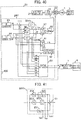
- Fig. 42 and Fig. 43 show an application example of the present embodiment.
- Fig. 42 is an example in which a plurality of electric motors and machine devices (four in Fig. 42 ) are connected in parallel. Even in the case where parallel-drivable AC electric motors such as induction electric motors are parallel-driven in this way, the present embodiment is effective in abnormality detection. For example, when only any of the four electric motors generates heat, the resistance value of the electric motor is increased, and hence a parameter value varies slightly. As a result, since the output of the integral compensation of the current controller varies, any of the four is abnormal, which can be detected by monitoring the value thereof.
- Fig. 43 is an example in which two electric motors and machine devices are connected. However, here, current sensors are provided in the respective electric motors. A value obtained by adding them is used for control, and individual coordinate conversion is used in monitoring a current value.
- the third embodiment there has been shown the example in which the monitoring device 5C is installed aside from the controller. However, by integrating the monitoring device with the controller in this manner, the internal phase ⁇ d of the controller can be utilized, thereby making it possible to monitor the current on the dq-axis for each electric motor. It is possible to infer whether any electric motor is abnormal, from a change in the value of each individual current and a change in the internal amount of each current controller.
- Fig. 41 illustrates a case where the electric motors are two as an example, but it is possible to perform monitoring similarly even in the case of three or more electric motors.
- the feature amount is extracted on the basis of the current deviation and the state amount obtained by performing proportion, integration, and differentiation on the current deviation, whereby it is possible to enhance the detection accuracy inclusive of transition and steadiness with respect to aging, an abnormal operation, or the sign of abnormality.
- the present embodiment shows an example in which a part of the embodiments described so far is applied for industrial equipment.
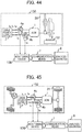
- Fig. 44 is an example in which the motor drive system is applied to a machine tool 150.
- a machine device 3X a cutting machine is connected to a rotating shaft of an electric motor 1.
- Fig. 44 shows a machine for performing machining to a material 151.
- Current sensors 4a and 4b are installed for the machine tool 150, and their currents are input to a monitoring device 5, where the conversion of the alternating current which has been described so far is performed to monitor it.
- a feature amount is analyzed by an analysis/diagnosis device 8 via a communication means 7.
- the feature amount can be made useful for monitoring of the consumables of the machine tool, quality control of a workpiece 151, and the improvement of yields.
- the cutting machine regardless of the cutting machine, it can be expanded even to other machining apparatuses such as an electric pressing machine, an injection molding machine, etc. Further, its application to industrial equipment like a fan, a pump, and a compressor is also considered.
- Fig. 44 has shown an example of the embodiment, but there is no problem even in combination with other embodiments described so far.
- the present embodiment shows an example in which a part of the embodiments described so far is applied to an electric vehicle 152.
- a machine device 3Y is connected to driving wheels of the electric vehicle.
- Current sensors 4a and 4b are installed, and their currents are input to a monitoring device 5, where the conversion of the alternating current which has been described so far is performed to monitor it.
- a feature amount is analyzed by an analysis/diagnosis device 8 via a communication means 7.
- the feature amount can be made useful for monitoring of the state of a drive system, deterioration of bearings, the wear of each tire, and a road surface state, etc. Further, it is also possible to provide a service of analyzing the waste of power consumption from long-term data and advising a driver, etc.
- Fig. 45 shows an example of the embodiment, but there is no problem even in combination with other embodiments described so far.
- the present embodiment shows an example in which the twentieth embodiment ( Fig. 42 ) is applied to an electric railway vehicle.
- a plurality of electric motors 1a to 1d are connected to a drive system of the electric railway vehicle.
- it is possible to monitor each electric motor by using Fig. 7 , Fig. 34 , Fig. 43 , etc.
- the resulting feature amount is analyzed by an analysis/diagnosis device 8 via a communication means 7.
- the feature amount can be made useful for monitoring of the state of a drive system, deterioration of bearings, the wear of each wheel, and the state of a track, etc. Especially, since it is possible to determine whether there is a risk of abnormality in any electric motor with respect to a plurality of electric motors, it is possible to save labor for maintenance work. Also, the aging of a mechanical system can be monitored from long-term data, and a change in the ambient temperature can also be monitored from the behavior of a current waveform of the electric motor. Further, it is also possible to provide a service of analyzing a change in power consumption and advising a driver, etc.
- the integration of the monitoring device with the drive power supply 2 rather than separately installing the monitoring device as in the case of the embodiments such as shown in the sixteenth to nineteenth embodiments makes it possible to use an installation space without being wasted.
- Fig. 46 shows an example of the embodiment, but there is no problem even in combination with other embodiments described so far.
- the present embodiment shows an example in which the embodiments described so far are applied to a household electrical appliance.
- monitoring is performed with a compressor 154 of an air conditioner 153 as a machine device.
- a feature amount can be made useful for monitoring of the driving state of the compressor, the deterioration of bearings, and the leakage of a refrigerant, etc.
- the integration of the monitoring device with the drive power supply 2 rather than separately installing the monitoring device as in the case of the embodiments such as shown in the seventeenth to twentieth embodiments makes it possible to use an installation space without being wasted.
- Fig. 47 shows an example of the embodiment, but there is no problem even in combination with other embodiments described so far.
- the monitoring device of the AC electric motor of the present invention is capable of not only monitoring the behavior of the AC electric motor, but also monitoring the behavior of the electric motor drive system including the drive power supply and machine device which are connected to the AC electric motor. For example, since the behavior of the machine device connected to the AC electric motor appears even in the current value of the AC electric motor, the monitoring of the machine device connected to the AC electric motor and the electric motor drive system can also be performed together by performing the monitoring of the AC electric motor.
- the present invention is a technique of realizing state monitoring of aging and abnormal detection, etc. of the electric motor drive system with the AC electric motor as power with high accuracy and in the minimum data quantity.
- the range of application for this technique is available from industrial applications such as a machine tool, a spindle motor, a fan, a pump (hydraulic pump, water pump), a compressor, a heating/cooling apparatus, etc. to an electric vehicle and a motor for a railway vehicle or the like.
Landscapes
- Engineering & Computer Science (AREA)
- Power Engineering (AREA)
- Physics & Mathematics (AREA)
- General Physics & Mathematics (AREA)
- Control Of Ac Motors In General (AREA)
- Control Of Electric Motors In General (AREA)
Abstract
Description
- The present invention relates to a monitoring device and monitoring method for an AC electric motor, and a monitoring device and monitoring method for an electric motor drive system.
- In the fields of industry, consumer electronics, transportation, etc., a control microprocessor used in a product has been made faster in speed and made higher in performance. At the same time, information communication by a network has also developed rapidly. As these results, IoT (Internet of Things) being the effort to connect things to the network and thereby make good use of huge information has been attracting attention. In the case of the industrial field, many sensors are placed in a machine tool or the like, and their information are analyzed to thereby improve the productivity of a manufacturing process and quickly detect an abnormality of the machine tool to help maintenance work. The maintenance work of a device is shifting from the monitoring operation based on the conventional operation time to the work based on state monitoring based on the sensor signal.
- There is a tendency that in order to perform monitoring of the device using the electric motor, current sensors are newly attached or sensors for temperature and vibration or the like are attached to the electric motor, and they are sampled in a constant cycle, and the resulting data is analyzed to perform state monitoring.
- In
Patent Literature 1, there has been shown a monitoring and optimization technique regarding the minimization of power consumption with an air-conditioning system as a target. At that time, environmental information are collected from many sensors to perform their analysis. - In
Patent Literature 2 andPatent Literature 3, there has been disclosed a technique of power-spectrum analyzing a phase current of an induction electric motor or a terminal voltage to detect an abnormality from the amount of generation of its sideband. - As shown in these known examples, an AC electric motor has been used for a power source for various applications. The monitoring of the entire system by observing the behaviors of these AC electric motors is expected to be increasingly important in future.
-
- Patent Literature 1: Japanese Patent Application Laid-Open No.
2015-1346 - Patent Literature 2: Japanese Patent Application Laid-Open No.
2016-195524 - Patent Literature 3: Japanese Patent Application Laid-Open No.
2016-197040 - As shown in
Patent Literature 1, it is possible to obtain a lot of information by arranging a large number of environmental sensors. There is however a tendency that the number of sensors is increased so that the number of data is also increased, and eventually, the enormous time is required for analysis after data acquisition. - Further, a current detection value becomes an AC amount because the AC electric motor is used. It is therefore necessary to sufficiently make a sampling period in data collection sufficiently shorter than the period of the alternating current in principle. For that reason, the amount of data is increased, and further, data processing at the analyzing time also takes time.
- In
Patent Literatures - The feature of the present invention for solving the above problems is as follows, for example.
- In a monitoring device of an AC electric motor, which monitors the AC electric motor driven by a drive power supply, the monitoring device converts a current detection value detected by a current detecting means of the AC electric motor into a DC amount, and outputs a feature amount on the basis of the DC amount.
- An effect obtained by a representative among the inventions disclosed in the present application will be briefly described as follows.
- According to the present invention, it is possible to greatly reduce the amount of data by treating a current flowing through an AC electric motor as a DC amount. Further, by converting AC into DC by a simple algorithm, edge processing for determining an abnormality can be performed in a monitoring device. Problems, configurations, and effects other than those described above will be clarified by the following description of embodiments.
-
-
Fig. 1 is a diagram showing the configuration of an electric motor drive system, an AC electric motor, and their monitoring device according to a first embodiment. -
Fig. 2 is a diagram showing operation waveforms according to the first embodiment. -
Fig. 3 is a diagram showing the configuration of an electric motor drive system, an AC electric motor, and their monitoring device according to a second embodiment. -
Fig. 4 is a diagram showing operation waveforms according to the second embodiment. -
Fig. 5 is a diagram showing the configuration of an electric motor drive system, an AC electric motor, and their monitoring device according to a third embodiment. -
Fig. 6 is a diagram showing operation waveforms according to the third embodiment. -
Fig. 7 is a diagram showing the configuration of an electric motor drive system, an AC electric motor, and their monitoring device according to a fourth embodiment. -
Fig. 8 is a diagram showing operation waveforms according to the fourth embodiment. -
Fig. 9 is a diagram showing the configuration of an electric motor drive system, an AC electric motor, and their monitoring device according to a fifth embodiment. -
Fig. 10 is a diagram showing operation waveforms according to the fifth embodiment. -
Fig. 11 is a diagram showing the configuration of an electric motor drive system, an AC electric motor, and their monitoring device according to a sixth embodiment. -
Fig. 12 is a diagram showing operation waveforms according to the sixth embodiment. -
Fig. 13 is a diagram showing the configuration of an electric motor drive system, an AC electric motor, and their monitoring device according to a seventh embodiment. -
Fig. 14 is a diagram showing the configuration of a feature extractor according to an eighth embodiment. -
Fig. 15 is a diagram showing operation waveforms according to the eighth embodiment. -
Fig. 16 is a diagram showing the configuration of a feature extractor according to a ninth embodiment. -
Fig. 17 is a diagram showing the configuration of a feature extractor according to a tenth embodiment. -
Fig. 18 is a diagram showing operation waveforms according to the tenth embodiment. -
Fig. 19 is a diagram showing the configuration of another feature extractor according to the tenth embodiment. -
Fig. 20 is a diagram showing the configuration of an electric motor drive system, an AC electric motor, and their monitoring device according to an eleventh embodiment. -
Fig. 21 is a diagram showing the configuration of a feature extractor according to the eleventh embodiment. -
Fig. 22 is a diagram showing operation waveforms according to the eleventh embodiment. -
Fig. 23 is a diagram showing the configuration of an electric motor drive system, an AC electric motor, and their monitoring device according to a twelfth embodiment. -
Fig. 24 is a diagram showing operation waveforms according to the twelfth embodiment. -
Fig. 25 is a diagram showing the configuration of an electric motor drive system, an AC electric motor, and their monitoring device according to a thirteenth embodiment. -
Fig. 26 is a diagram showing a physical model of an electric motor/machine device according to the thirteenth embodiment. -
Fig. 27 is a diagram showing a state observer according to the thirteenth embodiment. -
Fig. 28 is a diagram showing the configuration of an electric motor drive system, an AC electric motor, and their monitoring device according to a fourteenth embodiment. -
Fig. 29 is a diagram showing the configuration of a conduction ratio converter according to the fourteenth embodiment. -
Fig. 30 is a diagram showing the configuration of a current allocator according to the fourteenth embodiment. -
Fig. 31 is a diagram showing an operation of a switching element according to the fourteenth embodiment. -
Fig. 32 is a diagram showing the configuration of a feature extractor according to the fourteenth embodiment. -
Fig. 33 is a diagram showing operation waveforms according to the fourteenth embodiment. -
Fig. 34 is a diagram showing the configuration of a feature extractor according to a fifteenth embodiment. -
Fig. 35 is a diagram showing operation waveforms according to the fifteenth embodiment. -
Fig. 36 is a diagram showing the configuration of an electric motor drive system, an AC electric motor, and their monitoring device according to a sixteenth embodiment. -
Fig. 37 is a diagram showing the configuration of an electric motor drive system, an AC electric motor, and their monitoring device according to a seventeenth embodiment. -
Fig. 38 is a diagram showing the configuration of an electric motor drive system, an AC electric motor, and their monitoring device according to an eighteenth embodiment. -
Fig. 39 is a diagram showing the configuration of an electric motor drive system, an AC electric motor, and their monitoring device according to a nineteenth embodiment. -
Fig. 40 is a diagram showing the configuration of an electric motor drive system, an AC electric motor, and their monitoring device according to a twentieth embodiment. -
Fig. 41 is a diagram showing the configuration of a current controller according to the twentieth embodiment. -
Fig. 42 is a diagram showing the configuration of an electric motor drive system, an AC electric motor, and their monitoring device according to the twentieth embodiment. -
Fig. 43 is a diagram showing the configuration of an electric motor drive system, an AC electric motor, and their monitoring device according to the twentieth embodiment. -
Fig. 44 is a diagram showing the configuration of a machine tool device and a monitoring device according to a twenty-first embodiment. -
Fig. 45 is a diagram showing the configuration of an electric vehicle and a monitoring device according to a twenty-second embodiment. -
Fig. 46 is a diagram showing the configuration of an electric rail vehicle and a monitoring device according to a twenty-third embodiment. -
Fig. 47 is a diagram showing the configuration of an air conditioner outdoor unit and a monitoring device according to a twenty-fourth embodiment. - An embodiment according to the present invention will hereinafter be described using the accompanying drawings.
- An electric motor drive system, an AC electric motor, and their monitoring device according to a first embodiment of the present invention will be described using
Figs. 1 and 2 . - The electric motor drive system shown in
Fig 1 is intended to operate with a three-phase AC electric motor 1 (hereinafter simply abbreviated as an electric motor 1) as a power source, and is comprised of adrive power supply 2 of theelectric motor 1, and amachine device 3 with theelectric motor 1 as power. Thedrive power supply 2 is constituted by a power converter such as an inverter. Themachine device 3 is directed to industrial equipment such as fans, pumps, compressors, machine tools, etc., and apparatuses each using an electric motor, such as automobiles, railway vehicles, household appliances, etc. - A
monitoring apparatus 100 serves to monitor the operation of this system or the AC electric motor included in the system and detect aging and a malfunction, or the sign of an abnormal operation. In the present embodiment, it is assumed that themonitoring apparatus 100 is installed in the existing electric motor drive system as post installed one. A phase current of theelectric motor 1 detected by acurrent sensor 4a is processed by amonitoring device 5 from which data is transmitted to an analysis/diagnosis device 8 via a communication means 7. Thecurrent sensor 4a serves as a current detecting means and detects the phase current of theelectric motor 1. The phase current detected by the current detecting means is assumed to be a current detection value. The communication means 7 is constituted of a wired or wireless communication network. Further, it is also possible to temporarily store data in a flash memory even without always sending data to the analysis/diagnosis device via the communication means 7 and after a certain amount of data is accumulated, analyze it collectively. If the number of data is greatly reduced, and outside processing becomes unnecessary, analysis/diagnosis processing can also be executed inside themonitoring apparatus 100 without providing the analysis/diagnosis device 8. - The
monitoring apparatus 100 of the present embodiment will next be described. - The phase current (which is a U-phase current but may be any phase in
Fig. 1 ) detected by thecurrent sensor 4a being the current detecting means is read into themonitoring device 5 provided in themonitoring apparatus 100, and converted to a DC amount. Incidentally, themonitoring device 5 is intended to be realized by a microcomputer or FPGA, and actually read via an A/D converter (the AD converter is omitted inFig. 1 ). - Since an alternating current waveform changes momentarily sinusoidally, only simple sampling thereof makes it difficult to quickly detect the behavior of the electric motor (e.g., a load change or the impact of changes in machine device). For this reason, data cleansing is needed on top of shortening the sample period.
- In the present invention, a
multiplier 55 and a low-pass filter (LPF) 56 are used to convert an AC amount to a DC amount. The detected phase current Iu is squared by themultiplier 55, and then only a DC component I1 is extracted by the low-pass filter 56.Fig. 2 illustrates the waveforms of respective signals. - Using this I1, the behaviors of the electric motor drive system and the AC electric motor included in the electric motor drive system are monitored. A
feature extractor 6 extracts the magnitude of I1, a pulsating component contained in I1, and a transient fluctuation component thereof and thereby outputs a feature amount. The feature amount indicates e.g., aging, and a value or change indicative of an abnormal operation. Further, thefeature extractor 6 outputs, for example, at least one feature amount of the AC electric motor, the drive power supply, and the machine device. Then, thefeature extractor 6 sends the feature amount to the analysis/diagnosis device 8 via the communication means 7. Incidentally, the details of thefeature extractor 6 will be described in detail in seventh to eleventh embodiments. - As described above, according to the present invention, it is possible to convert the alternating current of the electric motor drive system into the amplitude of the current and monitor the same.
- An electric motor drive system, an AC electric motor, and their monitoring device according to a second embodiment of the present invention will be described using
Figs. 3 and 4 . - A block configuration diagram of the second embodiment is shown in
Fig. 3. Fig. 3 shows amonitoring device 5A introduced instead of themonitoring device 5 inFig. 1 . Incidentally, in parts inFig. 3 , those identical in part numbers to those inFig. 1 are identical to those inFig. 1 . - Using a zero-
cross measuring instrument 51, themonitoring device 5A measures a half cycle of the phase current Iu being the current detection value and determines the AC frequency of the alternating current. As shown inFig. 4 , a zero-cross period of the phase current is measured by using a timer of the microcomputer, and its value is assumed to be Tz. Using this measured time Tz, afrequency calculator 52 calculates the AC frequency (angular frequency) ω1. Incidentally, since Tz is the half cycle of the AC waveform, it can be calculated as ω1 = π/Tz. - Using this ω1, an
SIN wave generator 53 and aCOS wave generator 54 calculate sin (ω1 t) and cos (ω1 t), andmultipliers 55 are used to multiply them and the phase current waveform Iu with each other. Since an average value of the multiplication result of these becomes a value corresponding to a sin component and a cos component included in Iu, a sin component (x) and a cos component (y) can be extracted through low pass filters (LPF) 56. - Since x and y respectively coincide with the amplitudes of the sin component and cos component included in Iu, an AC
absolute value calculator 57 calculates the magnitude (amplitude) I1 of the phase current Iu. - In this way, the magnitude I1 and the angular frequency ω1 of the alternating current Iu are obtained every half cycle of the alternating current. Current information can be converted at a higher speed than when the power spectrum described in Patent Literature is used.
- Using these I1 and ω1, the behavior of the electric motor drive system is monitored. The
feature extractor 6 extracts the pulsating component and transient fluctuation component contained in I1 and ω1 and thereby outputs a feature amount. Then, as with the first embodiment, thefeature extractor 6 sends the feature amount to the analysis/diagnosis device 8 through the communication means 7. - As described above, according to the present invention, it is possible to convert the alternating current of the electric motor drive system into the amplitude and AC frequency of the current and monitor the same. Further, an observation period thereof can be shortened than when monitoring by the conventional power spectrum, and state monitoring including transient phenomena is made possible.
- An electric motor drive system, an AC electric motor, and their monitoring device according to a third embodiment of the present invention will be described using
Figs. 5 and 6 . - A block configuration diagram of the third embodiment is shown in
Fig. 5. Fig. 5 shows a case in which a W-phasecurrent sensor 4b being a current detecting means is added to the configuration diagram of the second embodiment ofFig. 3 , and further amonitoring device 5B is introduced instead of themonitoring device 5A. Incidentally, in parts inFig. 5 , those identical in part number to those inFig. 3 are identical to those inFig. 3 . - In the second embodiment, the AC amount being the current detection value has been converted into the DC amount only by the current sensor of one phase. On the other hand, the
monitoring device 5B detects two phases of motor currents of three phases and converts an alternating current being a current detection value into a DC amount. Consequently, it is possible to convert the alternating current to the DC current from instant to instant values without waiting for the calculation of the average value of a current waveform, and a zero cross signal. The detection of a shorter fluctuation component than the period of the alternating current is also possible. - In
Fig. 5 , themonitoring device 5B is comprised of aαβ converter 9 which converts a three-phase alternating current into alternating currents of orthogonal two phases, anarctangent calculator 10 which calculates, based on the two-phase alternating currents Iα and Iβ calculated by theαβ converter 9, its alternating current phase angle θi*, aphase calculator 11 which calculates a coordinate conversion phase θi relative to θi*, a rotating coordinateconverter 12 which coordinate-converts Iα and Iβ into Ir and Ii being biaxial DC amounts on the basis of an output θi of thephase calculator 11, and afeature extractor 6B which inputs therein Ir and Ii converted into the DC amounts, and an angular frequency ωrs being an internal amount of thephase calculator 11 to calculate a feature amount used in state monitoring. - Incidentally, the
phase calculator 11 is comprised of an adder 111 (where subtraction is performed) which calculates a deviation between the alternating current phase angle θi* and the coordinate conversion phase θi being the output of thephase calculator 11, aPLL controller 112 which performs PI control (proportional integral control) on the deviation and outputs the angular frequency ωrs, and anintegrator 113 which integrates ωrs being the output of thePLL controller 112 to calculate the coordinate conversion phase θi. - Next, the operation of the
monitoring device 5B will be described. - Based on Iu and Iw detected by the two-phase
current sensors αβ converter 9 converts them into two-phase alternating currents Iα and Iβ orthogonal to each other. The αβ conversion is calculated by the following (relative conversion):

- An αβ axis is the coordinates orthogonal to each other. The current phase θi* can be instantaneously calculated from values on the coordinates.

- The resulting θi* is an instantaneous value of a current phase. The rotating coordinate conversion can also be performed using this value, but in the present embodiment, the coordinate conversion phase θi is calculated through the
phase calculator 11. The reason for this is as described below. - Since a current ripple and noise are contained in the phase current, there is a possibility that when it is applied to the rotating coordinate conversion as it is, a large amount of ripples or noise are contained even in the converted DC amount. Therefore, the
phase calculator 11 is introduced while also serving as the purpose of reducing noise and the purpose of calculating the frequency of the alternating current. - Further, the
phase calculator 11 configures a control loop based on PLL control to thereby simultaneously perform the removal of noise and the frequency calculation of the alternating current. ThePLL controller 112 outputs the angular frequency ωrs such that the coordinate conversion phase θi being the output of theintegrator 113 and the current phase θi* coincide with each other. If θi and θi* coincide with each other, the output ωrs of thePLL controller 112 also coincides with the angular frequency of the alternating current, thus making it possible to obtain frequency information as well. Further, by setting the gain of thePLL controller 112, appropriate filtering is made, and the removal of noise is also possible. - In the PLL controller, the PI control (proportional integral control) is assumed to be performed, and the following calculation is performed.

- Incidentally, in the above equation, KpPLL means proportional gain, and KiPLL means integral gain. Incidentally, depending on the electric motor drive system, there are also applications performing rapid acceleration or deceleration of the
electric motor 1 frequently. In that case, improvements such as adding the squared term of integration may be performed rather than simple PI control. - The rotating coordinate
converter 12 converts Iα and Iβ into DC amounts on the basis of the coordinate conversion phase θi obtained in thephase calculator 11.

- The above Ir and Ii can be calculated for each calculation processing cycle of the
monitoring device 5B. It is possible to capture a sudden change in current or the like at that moment. - An operation waveform example of the present monitoring device is shown in
Fig. 6 . As illustrated inFig. 6 (a) , when the phase current waveform of theelectric motor 1 gradually changes, it is difficult to detect this change while remaining at an AC amount. Especially when a sample of current is rough, processing after data acquisition takes a lot of time. Alternatively, it is extremely difficult to extract only the change amount from the AC waveform continuing to originally change, such as where there is a periodicity in the change of the amplitude. - In the
monitoring device 5B, a three-phase AC is converted into two-phase alternating currents Iα and Iβ (Fig. 6(b) ). Thephase calculator 11 calculates a coordinate conversion phase θi (Fig. 6(c) ). At θi, minute phase variations of the alternating current (frequency variation) can also be detected. It can be detected as a change in the angular frequency ωrs shown inFig. 6(e) . Further, a change in current amplitude can also be captured as a change in the DC value as shown in theFig. 6(d) . These changes are determined by the processing cycle of themonitoring device 5B, but if the recent digital processing is introduced, processing in a cycle of about several 10µs is made possible, and state monitoring including transient phenomena is possible. - These changes in the current value (amplitude value) after conversion to the DC amount and in frequency are captured as the feature amounts by the
feature extractor 6B. After the amount of data has significantly been reduced, the data is transferred to the analysis/diagnosis device 8 through the communication means 7. By reducing the data, a communication load is greatly reduced. - The analysis/
diagnosis device 8 saves these feature amounts as time-series data and diagnoses a temporal change in the electric motor drive system. Since the conversion to a previously easy-to-analyze state amount is made in themonitoring device 5B, it is also easy to apply a diagnostic algorithm. - As described above, according to the present invention, in terms of the monitoring of the alternating current of the electric motor drive system, it is possible to convert the instantaneous current detection value to the amplitude and frequency, and the state monitoring including the transient phenomena can be realized.
- An electric motor drive system, an AC electric motor, and their monitoring device according to a fourth embodiment of the present invention will be described using
Figs. 7 and8 . -
Fig. 7 shows a block configuration diagram of the fourth embodiment. - In the present embodiment, the configuration of the electric motor drive system is characteristic. A plurality of (n)
electric motors 1a to 1n and a plurality ofmachine devices 3a to 3n are connected in parallel to a singledrive power supply 2. When an induction electric motor is used as an electric motor, such a configuration is possible. This is a configuration used in driving of transporting rollers of a rolling line in the steel industry, and a drive motor of a railway vehicle system, etc. - The
drive power supply 2 supplies power with a plurality of electric motors being regarded as a single electric motor. However, when the machine devices are respectively different in load, the loads on the electric motors are also different. There is a possibility that troubles such as a case in which a load is concentrated on a specific electric motor or machine device to remarkably wear only the machine, etc. will occur. - In order to monitor to which electric motor and to which machine device a heavy burden is applied, or whether an abnormality such as vibration or the like occurs, there is a need to monitor each individual electric motor. However, since it is difficult to extract the feature amount as described above when the current is monitored while remaining at the AC amount, it is desirable to convert the AC amount into a DC amount once and monitor the same.
- The present embodiment provides a state monitoring method of a system in which a plurality of electric motors are connected to a single drive power supply.
-
Fig. 7 shows that two current sensors corresponding to n numbers are added to n number of electric motors respectively, and amonitoring device 5C converts an alternating current of each electric motor into a DC amount and monitors the same. That is, a plurality of AC electric motors are driven by one drive power supply, and current sensors each being a current detecting means are provided in the respective AC electric motors. Incidentally, in parts shown inFig. 7 , those identical in part number to those shown inFig. 3 orFig. 5 are the same as those. - Next, the operation of the
monitoring device 5C of the present embodiment will be described. - Output currents (currents corresponding to all electric motors) of the
drive power supply 2 are detected by thecurrent sensors monitoring device 5B in the second embodiment. Incidentally, the current values of all the electric motors are set to be 1/n times atgains - U-phase and W-phase current sensors 4aa to n and 4ba to n are connected to the n electric motors. Their currents are αβ converted by
αβ converters 9a to n and further converted into DC amounts Ira to Irn and Iia to Iin by rotating coordinateconverters 12a to 12n respectively. - A coordinate conversion phase θi and an angular frequency ωrs are calculated from the value of the total current supplied from the
drive power supply 2. The rotational coordinate conversion of the current of each electric motor is calculated in a common phase θi. That is, by outputting the feature amount on the basis of at least one of the amplitude, phase and frequency contained in the DC amount, the difference between the operating states of the individual electric motors can be clearly detected. -
Fig. 8 shows operation waveforms of the present embodiment. Variation in current value of each motor can be captured as a DC amount with respect to Ir and Ii being an average current. For example, from the currents inFig. 8 (b) , it can be seen that the current Iia of theelectric motor 1a is generated in negative form. From this point of view, only theelectric motor 1a is seen to have been driven by a delayed phase current than the average value. Similarly, it can be seen that theelectric motor 1b and theelectric motor 1n assume a leading phase. It is understood from this waveform that there is a possibility that only theelectric motor 1a is being driven under operating conditions different from others, and some sort of abnormality occur. - It is difficult to perform such analysis by only the detected value of the AC current waveform. However, the introduction of the
monitoring device 5C makes it possible to facilitate feature extraction for detecting an abnormality and to considerably reduce the amount of data required for monitoring as well. - Incidentally, the embodiment has shown the example of placing two by two the current sensors in the electric motors, but the method using one current sensor such as shown in the first embodiment is also applicable if only monitoring of steady operation is taken. Further, the
current sensors drive power supply 2, are removed, and instead the values obtained from the current sensors of the individual electric motors are added together to also enable its result to be taken as information of the total current. - An electric motor drive system, an AC electric motor, and their monitoring device according to a fifth embodiment of the present invention will be described using
Fig. 9 and Fig. 10 . -
Fig. 9 shows a block configuration diagram of the fifth embodiment. -
Fig. 9 shows a feature that in the configuration diagram of the third embodiment shown inFig. 5 , arotation shaft sensor 14 is mounted to the rotating shaft of theelectric motor 1. Based on a signal detected by the rotation shaft sensor, electric motor control is performed by adrive power supply 2D. Further, as a monitoring device, amonitoring device 5D is introduced instead of themonitoring device 5B ofFig. 5 . Incidentally, in parts inFig. 9 , those identical in part number to those inFigs. 3 to 7 are the same as those. In the present embodiment, the rotation shaft sensor is used as a rotation shaft measuring means, but is not limited thereto. - In the embodiments described thus far, the current sensor is added to the existing electric motor drive system to monitor the electric motor drive system using only its current detection value. However, the rotation shaft sensor of the
electric motor 1 is connected as shown inFigure 9 , depending on the system. Further, depending on conditions, it may be possible to retrieve the signal of the rotation shaft sensor. The configuration of the present embodiment resides in that targeting such an electric motor drive system, the detected current is converted into a DC amount by utilizing the existing rotation shaft sensor. - In
Fig. 9 , therotation shaft sensor 14 is connected to the rotating shaft of theelectric motor 1, and is a pulse encoder which outputs pulse signals of A, B and z phases in accordance with the rotation of theelectric motor 1. The pulse encoder is a speed sensor generally used in an AC servo system or the like. It is possible to generate a position (angle) signal by integrating an output pulse train. To perform a home position alignment of a mechanical angle, a z phase to generate one pulse in one rotation is also assumed to be output. - A feature part of the present embodiment is that the pulse signals are diverted in the
monitoring device 5D to utilize the same for the coordinate transformation of the detected AC current. - In the
monitoring device 5D, a speed/position detector 15 counts the numbers of pulses of the A and B phases to thereby calculate the rotational speed of theelectric motor 1 and further integrates the pulse train to thereby calculate a phase θd of the rotation shaft. Since this θd is linked with the alternating current phase of theelectric motor 1, the current on the αβ-axis can be converted into a DC amount if rotating coordinate conversion is performed based on θd. Further, if resetting of the phase angle is done based on the z-phase signal, the coordinates of the dq-axis of theelectric motor 1 are obtained, whereby phase information of the inside of thedrive power supply 2D can be obtained. - In a rotating coordinate
converter 12D, a calculation is performed in the same manner as (Numeral 5) and (Numeral 6) based on the phase θd to convert the current into a DC amount. As a result of this conversion, a d-axis current and a q-axis current used for vector control of the AC electric motor can be calculated. Since the generated torque of theelectric motor 1 is proportional to the q-axis current, it is possible to monitor the generated torque of theelectric motor 1 by monitoring Iq. - Further, unlike the embodiment of
Fig. 5 , since it is not necessary to perform the phase calculation from Iα and Iβ, the influence of a delay due to the PLL controller can be eliminated, and more accurate state monitoring is made possible. -
Fig. 10 shows observed waveforms when the present embodiment is used. Changes in the current and a change in the rotational speed can be observed as with the waveform example ofFig. 4 . However, in the first to fourth embodiments, the current is converted into the DC amount on the basis of the phase of the current itself, whereas in the present embodiment, the conversion based on the information of the rotation shaft sensor is performed, and hence more precise movement of current can be captured. Further, since ωrs is a signal obtained from the actual rotation shaft sensor, the rotational speed itself is eventually detected. It is thus possible to realize more accurate monitoring. - Incidentally, even when one other than the pulse encoder, for example, a sensor such as a resolver, a Hall element or the like is used as the rotation shaft sensor, it is possible to achieve above realization similarly.
- An electric motor drive system, an AC electric motor, and their monitoring device according to a sixth embodiment of the present invention will be described using
Fig. 11 and Fig. 12 . -
Fig. 11 shows a block configuration diagram of the sixth embodiment. -
Fig. 11 shows a feature thatvoltage sensors electric motor 1 are attached to the configuration diagram of the third embodiment shown inFig. 5 . The voltage sensors serve to detect inter-line voltages Vuv and Vvw and thereby to help monitoring of the electric motor drive system. Further, as the monitoring device, amonitoring device 5E is introduced instead of themonitoring device 5B ofFig. 5 . Incidentally, in parts inFig. 11 , those identical in part number to those inFigs. 1 to 9 are the same as those. In the present embodiment, the voltage sensor is used as a voltage detecting means, but is not limited thereto. - The
monitoring device 5E inFig. 11 inputs the inter-line voltage Vuv, and Vvw therein, and converts the three-phase voltage into biphasic Vα and Vβ at anαβ converter 9E. The conversion from the inter-line voltage to the phase voltage can be calculated as follows:


arctangent calculator 10E calculates a voltage phase θv* on the basis of the equation (Vα is used instead of Iα, and Vβ is used instead of Iβ) shown in the (Numeral 3). Aphase calculator 11 is operated to control a coordinate conversion phase θv, so as to follow a voltage phase θv*. A rotating coordinateconverter 12E converts Iα and Iβ into DC amounts according to the phase of θv. - Since θv is the phase of the output voltage of the
drive power supply 2, the current observed on this coordinates is calculated as an active current in phase with an AC voltage and a reactive current orthogonal to the AC voltage. These coordinate transformation is calculated in accordance with a (Numeral 10) and a (Numeral 11) at the rotating coordinateconverter 12E, so that an active current component Iα and a reactive current component Iz can be determined.

- It can be seen that if the active current Iα is monitored, the load torque or power consumption is changed. Thus, the state monitoring of the
electric motor 1 and themachine device 2 can be carried out more accurately. -
Fig. 12 shows an example of current and voltage waveforms of theelectric motor 1, and waveforms of an active current Iα and a reactive current Iz obtained by themonitoring device 5E. The phase of the AC current waveform changes in the middle of the Figure, but the absolute value itself of the current has no change. Also, the frequency does not change either except during transition. In the present embodiment, themonitoring device 5E is capable of capturing that the current phase clearly changes by observing the current as the active current and the reactive current, and an increase in the active current, i.e., power consumption is also increased. - An electric motor drive system, an AC electric motor, and their monitoring device according to a seventh embodiment of the present invention will be described using
Fig. 13 . -
Fig. 13 shows that in the configuration diagram of the fifth embodiment shown inFig. 9 , without using the rotation shaft sensor of theelectric motor 1, phase information θd used inside adrive power supply 2F is drawn to the outside instead, and amonitoring device 5F converts an alternating current into a direct current on the basis of the phase information θd to perform state monitoring of the electric motor drive system. - First of all, description will be made in detail as to an internal configuration of the
drive power supply 2F of the embodiment shown inFig. 13 . Thedrive power supply 2F is an inverter for controlling theelectric motor 1 and is comprised thereinside of a maincircuit power supplier 21 which supplies power to an inverter main circuit unit, amain circuit 22 of the inverter which applies an arbitrary AC voltage to theelectric motor 1, acurrent sensor 23 which detects an AC output current of themain circuit 22, and acontroller 24 which controls the invertermain circuit unit 22 based on a current detection value obtained by thecurrent sensor 23. Thecontroller 24 calculates the phase information θd being an internal phase for vector control of theelectric motor 1. InFig. 13 , the rotation shaft sensor of theelectric motor 1 is not attached, and the estimation calculation of a rotation shaft position (angle) is performed inside thecontroller 24 to calculate θd. - The
monitoring device 5F receives the phase information θd being an internal value of thedrive power supply 2F and coordinate-converts the alternating current in the same manner as -
Fig. 9 , based on the phase information to calculate currents of a d-axis and a q-axis. Incidentally, the transfer of θd between thedrive power supply 2F and themonitoring device 5F is carried out via a serial communication, an analog signal, etc. Further, in order to calculate the frequency ωrs of the alternating current, a PLL controller may be newly introduced, or adifferential operation unit 25 may be introduced as shown inFig. 13 to calculate the angular frequency by differential operation. - As described above, according to the present embodiment, the state monitoring similar to that in the fifth embodiment (
Fig. 9 ) can be realized without using the rotation shaft sensor. - A monitoring device according to an eighth embodiment of the present invention will be described using
Figs. 14 and 15 . -
Fig. 14 shows a block configuration diagram of afeature extractor 6G usable in themonitoring devices feature extractor 6G for the feature extractor according to each of other embodiments. - The
feature extractor 6G of the present embodiment provides a function of extracting a vibration component from alternating currents Ir and Ii each converted into a DC amount, or from an angular frequency ωrs. - The
feature extractor 6G ofFig. 14 is comprised ofvibration component extractors memory 63 which stores the data. Thevibration component extractor 61a is comprised of a first-order lag filter 31a of a time constant Th, anadder 111, anabsolute value calculator 32, and a first-order lag filter 31b of a time constant Tj. - The operation of the
vibration component extractor 61a shown inFig. 14 will be described using a waveform example ofFig. 15 . - As an example of the waveform, the current Ir which has been converted into the DC amount, is assumed to include vibration such as shown in
Fig. 14(a) . Such vibration often occurs where, for example, a drive frequency of anelectric motor 1 and a mechanical resonance frequency of amachine device 2 match each other. Therefore, there occur such phenomena that when theelectric motor 1 is accelerating, vibration is generated when the drive frequency is approaching the mechanical resonance frequency, and vibration is suppressed again when exceeding the region of its rotational speed. If these vibration phenomena and an AC frequency at which they occur are associated with each other, an abnormality of the machine device and its changes with time can be detected, thereby making it possible to help state monitoring. - In the
vibration component extractor 61a, in order to extract only a vibration component included in the current Ir, a current value through the first-order lag filter of the time constant Th (as this current value, the average value at which the vibration component is canceled is output) is subtracted from the original Ir (theadder 111 being used as a subtractor inFig. 14 ) to thereby extract only the vibration component (a waveform of 'A' shown inFig. 15(c) ). Further, the absolute value of the signal 'A' is determined by theabsolute value calculator 32 to obtain a waveform of 'B' shown inFig. 15(d) . Since 'B' is a waveform like a full-wave rectification, it further passes through the first-order lag filter 31b of the time constant tj to output only a DC component (a waveform 'C' inFig. 15(e) ). That is, when vibration occurs in the direct current Ir, the vibration component is output as the value of the DC amount from thevibration component extractor 61a. In thesample switch 62, the waveform is sampled at predetermined intervals and stored in thememory 63. It is possible to extract a vibration component by performing the same processing even on the DC amount Ii. In any case, as compared to analyzing the alternating current waveform while remaining in the AC amount, the conversion of the AC amount into the DC amount enables a vibration component to be extracted by a simple algorithm. - Further, if the angular frequency ωrs of the alternating current is sampled simultaneously by the
sample switch 62 and stored in thememory 63, the correlation between the drive frequency and the vibration component can be stored as data. By analyzing the correlation, it can be utilized as a feature amount for determining a variation in a resonance point of the machine device, i.e., the wear and deterioration of the device. - Incidentally, in the present embodiment, there has been shown the example of extracting the vibration component included in the current, but the extraction of the vibration component of the angular frequency ωrs is also possible. Further, in the case of the third embodiment (
Fig. 7 ), the extraction of a vibration component for each electric motor is also possible with respect to each individual electric motor. - As described above, by using the feature extractor according to the present embodiment, it is possible to extract the vibration component in the simple algorithm, and it is possible to help state monitoring of the electric motor drive system.
- A monitoring device according to a ninth embodiment of the present invention will be described using
Fig. 16 . -
Fig. 16 shows a block configuration diagram of afeature extractor 6H usable in themonitoring devices feature extractor 6H for the feature extractor according to each of other embodiments. - The
feature extractor 6H of the present embodiment provides a function of specifying and extracting alternating currents Ir and Ii each converted into a DC amount, or pulsating components contained in an angular frequency detection value, up to the frequency. - When an electric motor is driven with an inverter as a drive power supply, there often occurs in the pulsating component of the current with a drive frequency as a primary component, vibration of the order of its integral multiple or the order of 1/integer times the frequency. Further, there is a possibility that the cause of the vibration can be specified depending on whether the vibration is generated in the vicinity of the drive frequency of any electric motor. Therefore, the execution of a frequency analysis with the drive frequency as the reference in real time is very important for the state monitoring.
- In
Fig. 16 , thefeature extractor 6H is comprised of pulsatingcomponent analyzers memory 63 which stores a result of its analysis. Further, the pulsatingcomponent analyzers frequency analyzers 65a to 65d,constant setters 66a to 65d, and sample switches 62. - As operations of the
frequency analyzers 65a to 65d, those quite equal to the calculation algorithm for the current amplitude I1 in the first embodiment are used. However, the angular frequency ω input to theSIN wave generator 53 and theCOS generator 54 is given by multiplying ωrs by constants (1, 2, 6, 0.5) set by theconstant setters 66a to 66d respectively. - In the
constant setter 66a, since '1' is set as a constant, ω = ωrs. As a result, thefrequency analyzer 65a performs extraction of the pulsating component of ωrs (i.e. the primary component of ωrs). Its calculation result Ir1 is sampled by thesample switch 62 and stored in thememory 63. - Similarly, the
frequency analyzer 65b, thefrequency analyzer 65c, and thefrequency analyzer 65d can extract a secondary component of ωrs, a 6-order component thereof, and a 1/2-order component thereof respectively. - In the present embodiment, the primary, secondary, sixth-order, and 0.5-order pulsating components can be extracted with respect to the drive frequency. These pulsation factors can be considered as follows.
- The primary component of the drive frequency is apt to occur when the offset current (DC component) of the drive power supply (inverter) occurs, and the abnormality of the drive power supply is estimated. Further, the secondary component is likely to occur when a three-phase imbalance has occurred. It occurs even such as where the electric motor is demagnetized by heating. As for the sixth-order pulsation, spatial harmonics of the electric motor, cogging torque, or strain of the inverter, or the like may be a factor. Further, when the number of poles of the electric motor is four, a load fluctuation for each revolution occurs as a 1/2-order pulsating component. Alternatively, even when the rotation shaft is made eccentric, the first-order component of a rotation frequency (1/2-order pulsating component of an electrical angular frequency if a four-pole machine is taken) is generated. Thus, depending on which pulsations of orders occur, it is possible to infer the cause thereof. Further, if such specific frequencies are extracted in the monitoring device, the work of subsequent analysis/diagnosis is easy, and hence it can help state monitoring.
- Incidentally, in the present embodiment, there has been shown the example of extracting the primary, secondary, 6-order, and 0.5-order pulsating components with respect to the drive frequency, arbitrary orders can be set for these.
- A monitoring device according to a tenth embodiment of the present invention will be described using
Figs. 17 and 18 . -
Fig. 17 shows a block configuration diagram of afeature extractor 6J usable in themonitoring devices feature extractor 6J for the feature extractor according to each of other embodiments, it is possible to realize the tenth embodiment. - The
feature extractor 6J of the present embodiment captures transient phenomena when alternating currents Ir and Ii each converted into a DC amount vary beyond a preset threshold value (predetermined range), and stores time-series data before and after it. - In the tenth embodiment, the transient phenomenon of the current Ir or Ii converted to the DC amount is captured, and a varying waveform before and after it is saved, thereby helping state monitoring.
- The
feature extractor 6J shown inFig. 17 is comprised of atrigger signal generator 67 which observes an amount of change in the current Ir converted into the DC amount and generates a trigger signal where it exceeds IR0 being a change amount set in advance, i.e., where it exceeds a predetermined range, sample value, samplevalue storing units 68a to 68c each of which stores values up to the previous n samples with respect to the currents Ir and Ii and angular frequency ωrs, and amemory 63. - In the
trigger signal generator 67, the amount of change in the current Ir is calculated by a first-order lag filter 31c and an adder 111 (operated as a subtractor in this case), and the amount of its change is compared with IR0 being a preset reference value in acomparator 33. IR0 is set at aconstant setter 66e. When a fluctuation occurs in Ir and Ir exceeds IR0, the output of thecomparator 33 becomes '1'. As the comparator output, the trigger signal is output via adelay circuit 34 with a delay of a delay time Tx. - The sample
value storage units 68a to 68c sequentially store the past sample values by one sample delay elements 69 (1/z), and store internal values up to past n samples. With the input of the trigger signal to the sample value storage unit, sample switches 62 simultaneously perform sampling, and n pieces of data are stored into thememory 63. A behavior waveform with the fluctuation in Ir as a trigger is stored in thememory 63. -
Fig. 18 shows the operation waveforms of the present embodiment. The waveforms show an example when the current waveform of Ir changes rapidly due to a load fluctuation or the like. When the current waveform exceeds the preset value IR0, the output of thecomparator 33 becomes '1'. However, via a delay time Tz therefrom, a trigger is given to the samplevalue storage units 68a to 68c. As a result, it is possible to store the transient phenomena at such timings as shown inFigs. 18(a), (b), and (c) . - N pieces of data of Ir, Ii, and ωrs being the past data at the transition are stored in the
memory 63 as shown inFig. 18(e), (f), and (g) . The transient phenomenon of the electric motor is an important factor relating to the control response. For example, when the electric motor constant is changed by temperature or the like, there is a high possibility that it can be observed as a difference in transient phenomenon. Thus, the relationship of transition between these currents and the drive frequency is stored as data and can be made useful in the analysis. The amount of variation to be used for analysis includes the amount of variation in the DC amount, or the amount of change in frequency used in converting the current detection value to the DC amount. - Similarly, there is shown in
Fig. 19 , the configuration of storing changes in the currents Ir and Ii with the time when the angular frequency ωrs fluctuates beyond the threshold value (predetermined range) as a trigger. Afeature extractor 6K and atrigger generator 67K are substantially the same as the embodiment ofFig. 17 , but different in that the factor of trigger occurrence is ωrs. Further, as a reference value of a speed variation, an angular frequency ωrs0 is set by aconstant setter 66f. Similarly toFig. 18 even in the present embodiment, with the angular frequency ωrs as the trigger, the waveform before and after the trigger occurs can be observed. The amount of variation used for the analysis in this case includes the amount of change in the frequency, or the amount of change in the DC amount. - As described above, according to the present embodiment, it is possible to capture the changes in the current and angular frequency caused by the transient phenomena of the electric motor and machine device and store their waveforms, thereby making it possible to help state monitoring and maintenance.
- An electric motor drive system, an AC electric motor, and their monitoring device according to an eleventh embodiment of the present invention will be described using
Figs. 20 to 22 . -
Fig. 20 shows a block configuration diagram of the eleventh embodiment. -
Fig. 20 shows a feature that in the configuration diagram of the third embodiment shown inFig. 5 , avibration sensor 35 is attached to anelectric motor 1. A vibration acceleration fx detected by this vibration sensor is read into amonitoring device 5L, and a feature amount is extracted by afeature extractor 6L. Other parts are the same as those ofFig. 5 in the third embodiment. -
Fig. 21 shows the configuration of thefeature extractor 6L. Thefeature extractor 6L show substantially the same configuration as that of thefeature extractor 6G of the seventh embodiment shown inFig. 14 . Avibration component extractor 61c which receives the vibration acceleration fx, and asample switch 62 for its output are added. With this configuration, it is also possible to extract a vibration component contained in fx in addition to the vibrations of currents Ir and Ii. - By extracting the vibration component of fx simultaneously with the vibration components of Ir and Ii, a new effect is obtained, and its description will therefore be made.
Fig. 22 shows the waveforms of the Ir, angular frequency ωrs, and vibration acceleration fx. When the drive frequency and the mechanical resonance frequency coincide with each other during acceleration, the large vibration has occurred. This has already been described usingFig. 15 . In the case of the vibration due to such mechanical resonance, it is confirmed that large vibration is observed even at the output fx of the vibration sensor, and is a mechanical resonance phenomenon. Further, there is a case where when acceleration is made to a high speed, for example, a vibration phenomenon like 'vibration 2' inFig. 22 occurs. In this case, no vibration is generated in the vibration sensor. From this point of view, it can be seen that the vibration phenomenon irrelevant to the mechanical resonance has occurred in Ir. In other words, vibration occurring in a control loop of an electric system irrelevant to a mechanical system can be read from these waveforms. - Thus, the correlation between the information of the external sensor and the DC amount is analyzed, and the feature amount is extracted, thereby making it possible to separate vibration factors and help state monitoring.
- Incidentally, the vibration sensor may be attached to the machine device, for example. Alternatively, a three-dimensional acceleration sensor may be used. Further, as the external sensor, instead of the vibration sensor, a noise sensor (microphone), a temperature sensor, or a humidity sensor may be used.
- Further, in the sense to perform association with the driving state of the electric motor, it is also considered that other sensor information are read and combined even in addition to the vibration sensor. For example, in the case of a compressor such as an air conditioner, if pressure sensor information of the machine device is used or information of the temperature sensor, the humidity sensor, etc. are captured simultaneously, the correlation with the driving state of the
electric motor 1 can be saved as data, thereby making it possible to help state monitoring. - An electric motor drive system, an AC electric motor, and their monitoring device according to an eleventh embodiment of the present invention will be described using
Figs. 23 and 24 . -
Fig. 23 shows a block configuration diagram of the twelfth embodiment. -
Fig. 23 illustrates a configuration in which in the configuration of the sixth embodiment shown inFig. 11 , amonitoring device 5M is introduced instead of themonitoring device 5E. Themonitoring device 5M has a configuration in which an active/reactive power calculator 36 is newly added, and calculates active power P and reactive power Q and inputs their calculated values to afeature extractor 6M. - In the sixth embodiment, the voltage information of the
drive power supply 2 is utilized based on the inter-line voltage information, and the alternating current of the electric motor is monitored by being separated into the active current component and the reactive current component. In the present embodiment, it is further monitored by being converted into the active power P and the reactive power Q. - The active/
reactive power calculator 36 performs the following operations using the current and voltage on a αβ-axis.

- Using at least one of the active power P and the reactive power Q calculated from the above equations, the
feature extractor 6M extracts and outputs a feature amount such as aging, an abnormal operation or the like. Then, the monitoring of states of the electric motor drive system and the AC electric motor is performed. - Sine the active power P means that the power consumption of the system is calculated instantly, it is possible to monitor the amount of power consumption of the system. Further, since it is possible to monitor how the amount of power consumption changes by stacking the number of years, it can help maintenance of the machine device.
-
Fig. 24 shows an example of monitored waveforms of the active power P and the reactive power Q. In the figure, figure, only the reactive power suddenly changes in the middle, and the angular frequency ωrs and active power P are not changed. It can be seen that when such a phenomenon is assumed to have occurred, the power consumption required for themachine device 3 remains unchanged, and only the reactive power increases (increases in the negative direction). As its factors, for example, it is expected that the original power supply voltage of thedrive power supply 2 is lowered, the magnitude of the voltage applicable to theelectric motor 1 is reduced, so that theelectric motor 1 is performing a weakening field operation. That is, it becomes possible to determine even abnormality of thedrive power supply 2. - By monitoring the values of the active power and the reactive power in this manner, it becomes possible to monitor the operating state of the electric motor drive system in more detail.
- An electric motor drive system, an AC electric motor, and their monitoring device according to a thirteenth embodiment of the present invention will be described using
Figs. 25 to 27 . -
Fig. 25 shows a block configuration diagram of the thirteenth embodiment. -
Fig. 25 shows a configuration in which in the configuration of the sixth embodiment shown inFig. 11 , amonitoring device 5N is introduced instead of themonitoring device 5E. Themonitoring device 5N is added with a rotating coordinateconverter 12E which coordinate-converts Vα and Vβ at a phase angle θv, and astate observer 37 at which voltages Va and Vz on the rotating coordinates are computed and which further observes an internal state amount of theelectric motor 1. Thestate observer 37 observes a state amount of the system which is not detected directly, by estimating and calculating the same, thereby helping monitoring. In the present embodiment, the estimation calculation of generated torque Tm of theelectric motor 1 and load torque TL thereof each being the state amount of the system is performed on the basis of a mathematical model of theelectric motor 1 and a mathematical model of themachine device 2. A feature extractor 6N inputs therein Ia, Iz, Va, Vz, ωrs, etc. in addition to the output of thestate observer 37 and performs state monitoring at the time of steady-state and transition. -
Fig. 26 shows a physical model representing the relationship between the motor torque Tm, the load torque TL, and the angular frequency ωrs in a block diagram. As shown in the figure, it can be seen that the rotational speed of a mechanical angle is obtained by the difference between the torque Tm generated by theelectric motor 1 and the load torque TL generated by themachine device 3, inertia J of a mechanical system including an electric motor, and a damping coefficient D. Further, by multiplying it by the number of pole pairs Pole/2 of theelectric motor 1, the electrical angular frequency ωrs of theelectric motor 1 can be obtained. With these block diagrams as the principle, thestate observer 37 calculates back the load torque TL. -
Fig. 27 shows a block configuration of thestate observer 37. In the figure, with the voltages Va and Vz and the currents Ia and Iz after the rotating coordinate conversion being taken as inputs, amotor model 371 being a mathematical model of theelectric motor 1 determines the generated torque Tm of theelectric motor 1 by calculation. Further, an inverse model of the physical model to obtain the angular frequency ωrs shown inFig. 26 is implemented by a gain 372 (the inverse of the number of pole pairs) and an imperfect differentiator 373 (inverse model of the machine device) to calculate the load torque TL. Incidentally, a time constant Tobs of denominator in theimperfect differentiator 373 is observer gain. It is possible to adjust the band of a frequency component included in TL by this time constant. - By using the state observer shown in
Fig. 27 , the generated torque Tm of theelectric motor 1 and the load torque TL which are difficult to be detected directly can be determined using a mathematical model. For example, the torque vibration of the machine device, etc. can also be observed by thestate observer 37. This can help state monitoring. Incidentally, the feature extractor 6N may perform processing such as the vibration component extraction, output, etc. which have been described thus far. - Further, as the model of the machine device, the various state amounts can be calculated by introducing a physical model as a more detailed mathematical model. This is available even for monitoring of the vibration of a vehicle body, the effectiveness of a suspension, or a road surface state, etc. by simulating the body of an automobile, for example.
- By introducing the state observer inside the monitoring device as described above, the new state amounts such as the generated torque, the load torque, etc. can be determined by calculation, thus making it possible to help state monitoring.
- An electric motor drive system, an AC electric motor, and their monitoring device according to a fourteenth embodiment of the present invention will be described using
Figs. 28 to 33 . -
Fig. 28 shows a block configuration diagram of the fourteenth embodiment. -
Fig. 28 illustrates a configuration in which in the configuration of the sixth embodiment shown inFig. 11 , the details of adrive power supply 2 are described, and amonitoring device 5P is introduced instead of themonitoring device 5E. - The previous embodiments have been constructed mainly for the purpose of the state monitoring of the
electric motor 1 and themachine device 3. However, the present embodiment is intended to monitor operating states of switching elements (T1 to T6 and D1 to D6) constituting an inverter main circuit. - In
Fig. 28 , thedrive power supply 2P is comprised of aDC voltage source 21 of a voltage VDC, a three-phase full-bridge invertermain circuit unit 221, agate driver 222 to give a gate signal to each switching element, acurrent sensor 23, and acontroller 24. - The
monitoring device 5P has a function of separating an alternating current to an active current and a reactive current, based on a voltage sensor as with the embodiment ofFig. 11 . Further, themonitoring device 5P monitors the operating state of each switching element of the invertermain circuit unit 221. Functions newly added from themonitoring device 5E are as follows. - The
monitoring device 5P is constituted of an adder 111 (operated as a subtractor here) which calculates a V-phase current from U-phase and W-phase currents, aconduction ratio converter 38 which converts an inter-line voltage to a conduction ratio (duty),current allocators 39a to 39c which assign the phase currents to the respective switching elements, and afeature extractor 6P which converts the outputs of these current allocators into feature amounts. - On the basis of the voltage applied to the
electric motor 1 and the current flowing therethrough, themonitoring device 5P determines by calculation how much current flows to any of the switching elements of the invertermain circuit unit 221 to thereby monitor the power balance and monitor whether or not current concentration occurs. -
Fig. 29 shows an internal configuration of theconduction ratio converter 38. Since the inter-line voltages Vuv and Vvw are pulse voltages, pulse components thereof are removed by first-order lag filters of time constant Tfc and then they are converted to phase voltages. InFig. 29 , the calculation of (Numeral 7) through (Numeral 9) is performed usinggains 116 and 117 andadders 111. - Duty ratios Du to Dw are calculated by adding the value of 1/2 of the DC power supply to the resulting phase voltages Vu, Vv and Vw (performing setting by a constant setter 66g) and multiplying them by gains 119 (performing setting to 1/VDC). Consequently, Du to Dw varies in a range of 0.0 to 1.0. Incidentally, as in the seventh embodiment (
Fig. 13 ), if it is possible to directly obtain the duty ratios Du to Dw from thecontroller 24, theconduction ratio converter 38 may be omitted. - Next, the operations of the
current allocators 39a to 39c will be described usingFigs. 30 and 31 . - The respective
current allocators 39a to 39c are equivalent to the arms of the respective phases of the invertermain circuit unit 221. If the U phase is taken, conduction currents of IGBT T1 and T4 and reflux diodes D1 and D4 are calculated. - In
Fig. 30 , the polarity of the phase current Iu is determined by aswitch 70. If it is 'positive', the switch is changed to a p side, and if it is 'negative', the switch is changed to an n side. If the current is 'positive', there are two types where, as shown inFigs. 30(a) and (b) , T1 being the upper IGBT is turned on, and the lower diode D4 is turned on. The proportion of current between T1 and D4 is determined by the duty Du of switching of the U-phase. Since the ratio at which T1 is turned on is proportional to Du, Iu and Du are multiplied by amultiplier 55 and its result is output as a current value IT1 of T1. Since a current of D4 is the remaining proportion of Du, 1-Du is determined by aconstant setter 118 and the adder 111 (operated as a subtractor here), and Iu×(1-Du) is calculated by themultiplier 55 and output as ID4. - Similarly, when the phase current Iu is negative, as shown in
Figs. 30(c) and (d) , either D1 or T4 is turned on, and Du and (1-Du) are respectively multiplied to calculate a current ratio. Incidentally, since even the current of the negative side is assumed to be 'positive' for the switching element (the current flows only in one direction), the polarity of the negative-side current is reversed using again 120. - In this way, the phase current can be assigned to each of the respective switching elements.
- The current values IT1 to IT6 and ID1 to ID6 of the respective switching elements calculated in this way are converted into the feature amounts by the
feature extractor 6P.Fig. 32 shows the configuration of thefeature extractor 6P. - In the
feature extractor 6P, devicestate monitoring units 40a to 40L are aligned and respectively calculate temperature-corresponding state amounts T_IT1 to 6 and T_ID1 to 6 and operation-history corresponding state amounts S_IT1 to 6 and S_ID1 to 6 of 12 pieces of switching elements. The configuration of the device state monitoring unit 40 is constituted of a first-order lag filter 31d of a time constant Tn, anintegrator 113, and asample switch 62. The first-order lag filter 31d is required to match the time constant with a temperature time constant of each switching element. By matching the time constant with the temperature time constant, the operating temperature of each device can be estimated and calculated. Also, viewed from another angle, it is possible to monitor whether an offset current flows in any device. - In general, the load characteristics of the
machine device 3 often becomes three-phase balanced. However, for example, in the case where a reciprocating compressor or the like is driven, a load fluctuation occurs in the same cycle as the rotation cycle, and hence a load current is likely to concentrate on the particular switching element. Such an offset state can be monitored by this feature extractor. - Further, by integrating the current by the
integrator 113, the history of the device can be saved. By accumulating and analyzing history data, it is possible to help life prediction of the device. -
Fig. 33 shows an example of waveforms of the outputs T_IT1 and S_IT1 of the devicestate monitoring unit 40a. It can be seen that T_IT1 varies with the operation of the electric motor drive system. Further, it is possible to confirm a state of S_IT1 leaving a history by integrating an operating current. - A monitoring device according to a fifteenth embodiment of the present invention will be described using
Figs. 34 and 35 . -
Fig. 34 shows a block configuration diagram of the fifteenth embodiment. - The present embodiment can be realized by replacing the
feature extractor 6C of the fourth embodiment shown inFig. 7 with amonitoring device 6Q shown inFig. 34 . - In the fourth embodiment, the drive currents of the plural (n) electric motors have been subjected to the rotating coordinate conversion in the same phase to monitor the operating states of the individual electric motors. In the present embodiment, in order to clearly extract the difference in operating state between the n electric motors, the current of each electric motor is converted to extract a feature amount.
- As shown in
Fig. 34 , thefeature extractor 6Q is comprised of polar coordinateconverters 71a to 71x each of which converts a current of a DC amount subjected to rotating coordinate conversion (transformation on the orthogonal coordinates of two axes) into polar coordinates, and amemory 63Q. - The polar coordinate
converters 71a to 71x are respectively constituted of anarc tangent calculator 10, an ACabsolute value calculator 57, anadder 111, and asample switch 62, which are the parts described so far. - As described in the third embodiment, the currents of the respective electric motors are subjected to the rotating coordinate conversion based on the total current to obtain Ira to Irn and Iia to Iin respectively.
- The polar coordinate
converter 71x computes, in terms of Ir and Ii being the average current, an angle δ1 formed by the two at thearc tangent calculator 10, calculates I1 being the magnitude at the ACabsolute value calculator 57, samples its value by thesample switch 62, and saves the same into thememory 63Q. The feature part of the present embodiment is that the feature amount of the current of each electric motor is determined based on δ1 and I1 obtained with the average current. - The differences between the average I1 and δ1 determined in the polar coordinate
converter 71x and Ia to In and δa to δn calculated similarly by the respective electric motors are respectively calculated and stored in thememory 63P as dIa to dIn and dδa to dδn. Since dIa to dIn and dδa to dδn are amounts shifted from the average value, it is possible to monitor how much the current amplitude is shifted, or how much the phase difference is generated. That is, the operating state of each AC electric motor can be calculated based on at least one of the phase of the current flowing through the AC electric motor and the amplitude thereof. -
Fig. 35 shows a waveform example of these feature amounts. - In
Fig. 35 , a drive frequency ωrs is increased, the electric motor is in a state of being accelerated, and the average current amplitude I1 is increased slightly but does not change greatly. It can however be seen that dIa is increased in proportion to the speed, and dIb has a constant deviation without depending on the speed. From this view, theelectric motor 1a can determine that an error proportional to the rotational speed is being generated. That is, the operating state of each AC electric motor can be separately calculated. In terms of the error proportional to the rotational speed, it is considered that in the case of an electric motor for a railway vehicle, a difference in wheel diameter occurs, and only theelectric motor 1a is increasing in load with the rotational speed. Further, it is considered that anelectric motor 1b having an almost constant error without depending on the load has a possibility that an error occurs in the constant. - Thus, according to the present embodiment, the electric motor drive system which drives the plurality of electric motors with one drive power supply is capable of separating the differences in operating state between the respective electric motors and outputting the feature amount. It is thus possible to help state monitoring.
- An electric motor drive system, an AC electric motor, and their monitoring device according to a sixteenth embodiment of the present invention will be described using
Fig. 36 . - The present embodiment resides in that in the configuration diagram of the seventh embodiment shown in
Fig. 13 , thecontroller 24 is replaced with acontroller 24R shown inFig. 36 and further Id and Iq being internal state amounts of thecontroller 24R are drawn to the outside, and feature extraction is performed in amonitoring device 5R. Themonitoring device 5R is comprised of afeature extractor 6R. Then, state monitoring is performed by a analysis/diagnosis device 8 through a communication means 7. - A
drive power supply 2R performs vector control of anelectric motor 1, and the details of its operation are described in thecontroller 24R ofFig. 36 . - In the
controller 24R, the phase current of theelectric motor 1 is detected by acurrent sensor 23 provided inside thedrive power supply 2R and then converted into a DC amount using a phase angle θd at a dq coordinateconverter 81. θd used for coordinate conversion is calculated in a speed/phase calculator 82. Incidentally,Fig. 36 shows the configuration of speed-position sensorless control not using the rotation shaft sensor in theelectric motor 1, but there is no problem even if these sensors are used. - In the dq coordinate
converter 81, the phase current of theelectric motor 1 is converted into the currents Id and Iq on the d- and q-axes each being a DC amount, which are respectively used for vector control. In terms of the d-axis current Id, the difference between the d-axis current Id and a d-axis current command Id* output from an Id*generator 83 is calculated by anadder 111, and controlled by a current controller (ACR) 85a such that the deviation therebetween becomes zero. Similarly, in terms of the q-axis current Iq, the difference between the q-axis current Iq and a q-axis current command Iq* output from an Iq*generator 84 is calculated by anadder 111, and controlled by a current controller (ACR) 85b so that the deviation therebetween becomes zero. Further, amotor model calculator 86 performs voltage operation by a mathematical model based on the constants of theelectric motor 1, and adds its outputs to the outputs of therespective ACR inverse converter 87, and then converted into a pulse train by a PWM (pulse width modulation)generator 88, thereby driving an inverter of a main circuit. The current controller executes control so that the deviation becomes zero on the rotating coordinate axes synchronized with the AC voltage output from the drive power supply. - Incidentally, each of the Id*
generator 83 and the Iq*generator 84 means a command generator in the upper order of the current controller. For example, it is a block including a speed controller (ASR) or the like controlling the speed of theelectric motor 1. - As described above, the drive power supply in the electric motor drive system often constitutes a vector control system as shown in
Fig. 36 . In that case, the controller often performs control thereinside by converting the alternating current into the DC amount once. The present embodiment is characterized by diverting the coordinate conversion in thecontroller 24R and retrieving the DC amount after the conversion thereof to the outside. At this time, thecontroller 24R transmits the values of Id and Iq to themonitoring device 5R by performing serial or parallel communications, or conversion to an analog value, etc. In theexternal monitoring device 5R, thefeature extractor 6R executes extraction of a feature amount with respect to the received Id and Iq. Thus, if it is possible to utilize the amount of an internal state of thecontroller 24R, the operation of themonitoring device 5R becomes very simple, thereby making it possible to greatly reduce a processing load factor of thefeature extractor 6R and utilize an inexpensive microcomputer. - Moreover, there is also an advantage that the reduction in the calculation load factor of the microcomputer enables the extraction of various feature amounts to be executed simultaneously. For example, the algorithms of the feature extractors in
Figs. 14 ,16 ,17 ,19 , etc., described thus far are processed in parallel to make it also possible to enhance monitoring. Further, even if the control internal state amount other than Id and Iq, e.g., ωr or the like is drawn to the outside, no problem occurs. - As described above, according to the present embodiment, the control internal state amount of the electric motor drive system is drawn to the outside, thereby making it possible to reduce the load of the monitoring device, and further achieve monitoring by conversion to the various feature amounts.
- An electric motor drive system, an AC electric motor, and their monitoring device according to a seventeenth embodiment of the present invention will be described using
Fig. 37 . - The present embodiment resides in that in the configuration diagram of the sixteenth embodiment shown in
Fig. 36 , thecontroller 24R is replaced by acontroller 24S shown inFig. 37 , themonitoring device 5R is eliminated, and instead afeature extractor 6S is installed inside thecontroller 24S. A feature part of the present embodiment resides in that the role of the monitoring device is included in adrive power supply 2S. Therefore, the output of thefeature extractor 6S is transferred through a communication means 7 directly from thedrive power supply 2S to an analysis/diagnosis device 8. - If the
drive power supply 2S is provided thereinside with a monitoring function, i.e., the controller and thefeature extractor 6S being a feature extracting means are operated on a signal processing device in which they are integrated, adverse effects to communications are eliminated, and more internal amounts can be utilized. - Ass shown in
Fig. 37 , for example, since state amounts such as voltage commands Vd* and Vq*, a rotational speed ωr, etc. can also be utilized, the calculation of active/reactive power shown inFig. 23 , the use of the observer shown inFig. 25 , the monitoring of the switching element shown inFig. 28 , etc. can also be mounted simultaneously. - In that case, the calculation load factor of the
controller 24S increases, but if design such as using a recent multi-core microcomputer, sharing a bus in multiple microcomputers, etc. is performed, the implementation of such an algorithm is easy. Of course, it is necessary to take substantial review of a software structure for the existing device. However, the above is a very effective means when developing a drive power supply with a pre-monitoring function. - According to the present embodiment as described above, it is possible to extract various feature amounts without drawing the internal amount of the electric motor drive system to the outside. That is, using at least either the current value on the rotating coordinate axes used in the controller or the voltage value on the rotating coordinate axes as the DC amount, the feature extractor outputs the feature amount on the basis of at least one of any DC amount and the rotational speed used in the controller. It is thus possible to realize the monitoring of the electric motor drive system.
- An electric motor drive system, an AC electric motor, and their monitoring device according to an eighteenth embodiment of the present invention will be described using
Fig. 38 . - The present embodiment resides in that in the configuration diagram of the seventeenth embodiment shown in
Fig. 37 , thecontroller 24S is replaced by acontroller 24T shown inFig. 37 , and further constitutes position sensorless control not using the rotation shaft sensor with theelectric motor 1 as a permanentmagnet electric motor 1T. - As a block configuration diagram, in order to perform the position sensorless control of the permanent magnet electric motor, an
axial error calculator 82T is introduced instead of the speed/position calculator 82 inFig. 37 , andfurther adders 111, aPLL controller 112, and anintegrator 113 are added. Moreover, thefeature extractor 6S is changed to afeature extractor 6T. - As the position sensorless control of the permanent magnet electric motor, there are various methods. There is however often used a method of calculating a deviation (it is assumed to be an axial error Δθd) between an actual rotor position θd of the electric motor, and a phase angle estimated inside the
controller 24T, and controlling its value in such a manner that the value becomes zero. - The
controller 24T inFig. 38 shows its example. In theaxial error calculator 82T, the axial error occurring between the electric motor and the controller is calculated, and theadder 111 and thePLL controller 112 are used to calculate a drive frequency ωr of the electric motor so that the value of the axial error becomes zero. By adjusting ωr, the control internal phase θd is adjasted, thereby controlling the axial error Δθd to zero. - In this position sensorless control system, the internal amount called the 'axial error Δθd' is a very important value, and the generated amount of this deviation is intended to determine the stability of the system. In the steady state, Δθd is controlled to zero, but at the time of a transient response, the time of occurrence of a constant error, etc., there is a case where a deviation occurs in Δθd. This is because, as its major factor, a response delay related to a control response occurs inevitably where a load change occurs (primarily, the operation related to setting gain of the PLL controller 112). If paradoxically grasped, it is possible to infer from the movement of Δθd at the load change, what kind of load change has occurred. Further, it is considered that even if there is no change in load itself, a change occurs in the movement of Δθd even where motor parameters and mechanical parameters change due to aging.
- Therefore, the monitoring of Δθd is extremely important. If the
feature extractor 6T performs the conversion thereof to the feature amount and its monitoring on the basis of the axial error, it is possible to quickly detect changes of the electric motor and the machine device, and the sign of abnormality. Thefeature extractor 6T carries out analysis of a variation component of the axial error Δθd and frequencies, etc. through the various algorithms described in the previous embodiments. That is, thefeature extractor 6T outputs the feature amount on the basis of the axial error. It is thus possible to more quickly an abnormal state. Further, an important variable is obtained as a factor to perform analysis/diagnosis. - According to the present embodiment as described above, in the electric motor drive system using the position sensorless permanent magnet electric motor, the monitoring device can be realized which is capable of improving detection accuracy with respect to aging, abnormal operations, or the sign of abnormality.
- An electric motor drive system, an AC electric motor, and their monitoring device according to a nineteenth embodiment of the present invention will be described using
Fig. 39 . - The present embodiment resides in that in the configuration diagram of the seventeenth embodiment shown in
Fig. 37 , thecontroller 24S is replaced by acontroller 24U shown inFig. 39 , and configures speed sensorless control not using the rotation shaft sensor with theelectric motor 1 as an inductionelectric motor 1U. - As a block configuration diagram, in order to perform the speed sensorless control of the induction electric motor, a speed calculator 82U is introduced instead of the speed/
position calculator 82 inFig. 37 , and further aslip frequency calculator 91 and amagnetic flux estimator 92 are added. Moreover, thefeature extractor 6S is changed to afeature extractor 6U. - As the speed sensorless control of the induction electric motor, there are various methods, but the speed calculator 82U estimating an actual rotational speed ωr of the electric motor, and the
slip calculator 91 calculating a sip frequency ωs of the induction electric motor become important blocks. Further, unlike the permanent magnet electric motor, it is necessary to control a magnetic flux by an excitation current (Id). φ2d being its d-axis magnetic flux is controlled constant, and φ2q being a q-axis magnetic flux is controlled to be zero. In principle, by adjusting the slip frequency ωs to the torque of the electric motor, φ2d can be controlled constant, and φ2q can be controlled to zero. The torque can be made proportional to φ2d×Iq. - Conversely, when φ2d varies and further φ2q is generated, the value of the slip frequency ωs is not appropriate. In the present embodiment, the
magnetic flux estimator 92 is introduced to perform magnetic flux estimation operation of the inside of the induction electric motor, and thefeature extractor 6U performs extraction of a feature amount. By performing monitoring of such a state amount, it is possible to separate variations, for example, depending on whether the slip frequency ωs and the magnetic fluxes φ2d and φ2q fluctuate with a phase relationship or they are independent of each other. If they fluctuate with the correlation, there is a high possibility that the load itself of the machine device is fluctuating. If there is no correlation in reverse, the possibility of a constant fluctuation of the induction electric motor is considered. Thus, by monitoring the control internal amount of the induction electric motor, separation when an abnormal operation is detected can be performed. - According to the present embodiment as described above, in the electric motor drive system using the speed sensorless induction electric motor, the monitoring device can be realized which is capable of improving detection accuracy with respect to aging, abnormal operations, or the sign of abnormality.
- An electric motor drive system, an AC electric motor, and their monitoring device according to a twentieth embodiment of the present invention will be described using
Fig. 40 . - The present embodiment resides in that in the configuration diagram of the seventeenth embodiment shown in
Fig. 37 , thecontroller 24S is replaced by acontroller 24V shown inFig. 40 . In thecontroller 24V, current controllers 85Va and 85Vb and a feature extractor6V are changed. - The configuration of each of the current controllers 85Va and 85Vb is shown in
Fig. 41 . Generally, the current controller constitutes a PID controller similarly even in the present embodiment though PI control (proportional integral control) or PID control (proportional-integral-derivative control) is performed. InFig. 41 , the current controller 85Va is comprised of aproportional gain 851, an integral gain 852, an integrator 853, and adifferential gain 854, an incompletederivative element 855 of a time constant Tp, and anadder 111. Further, Vdkp, Vdki, and Vdkd each being the output of each compensator are to be drawn to the outside of a block. The q-axis current controller 85Vb is also similar in configuration and serves to draw outputs Vqkp, Vqki, and Vqkd of respective compensators to the outside of a block. The internal amounts of these controllers, and further ΔId (=Id*-Id) and ΔIq (=Iq*-Iq) each being a current deviation are input to the feature extractor 6V to extract feature amounts. - Since the current controller is generally operated to set the deviation (ΔId, ΔIq) to zero, ΔId and ΔIq in the steady state converge to zero. However, though the value is generated in a transient state such as at the time of a command change and a load change, the movement at the time of transition changes with the state of the
electric motor 1,machine device 3 or maincircuit power supply 2. That is, 'abnormality' or 'sign of abnormality' undetectable in the steady state can be monitored from the movement of the deviation of the controller. - Further, since the current controllers 85Va and 85Vb are for performing proportion, integration and differentiation on these current deviations, the influence of the deviation occur even herein. In particular, the output of the integrator is placed in a relationship which occurs even steadily.
- For example, a
motor model calculator 86 calculates the voltage required in the steady state as feedforward. However, if the parameter in it deviates from the actual electric motor, its shift amount is steadily compensated by integral compensation of the current controller. Therefore, factors for constant fluctuation steadily occur in Vdki and Vqki. Further, since the response of the current control is determined by a proportional gain kp and a differential gain Kd, it is desirable to monitor the outputs of these compensators and monitor the transient feature amount for detecting the abnormal operation during transition. - Therefore, it can be said that it is extremely beneficial to extract the feature amount from the internal amounts of these current controllers and the current deviations.
-
Fig. 42 andFig. 43 show an application example of the present embodiment. -
Fig. 42 is an example in which a plurality of electric motors and machine devices (four inFig. 42 ) are connected in parallel. Even in the case where parallel-drivable AC electric motors such as induction electric motors are parallel-driven in this way, the present embodiment is effective in abnormality detection. For example, when only any of the four electric motors generates heat, the resistance value of the electric motor is increased, and hence a parameter value varies slightly. As a result, since the output of the integral compensation of the current controller varies, any of the four is abnormal, which can be detected by monitoring the value thereof. - Further,
Fig. 43 is an example in which two electric motors and machine devices are connected. However, here, current sensors are provided in the respective electric motors. A value obtained by adding them is used for control, and individual coordinate conversion is used in monitoring a current value. In the third embodiment, there has been shown the example in which themonitoring device 5C is installed aside from the controller. However, by integrating the monitoring device with the controller in this manner, the internal phase θd of the controller can be utilized, thereby making it possible to monitor the current on the dq-axis for each electric motor. It is possible to infer whether any electric motor is abnormal, from a change in the value of each individual current and a change in the internal amount of each current controller. Incidentally,Fig. 41 illustrates a case where the electric motors are two as an example, but it is possible to perform monitoring similarly even in the case of three or more electric motors. - According to the present embodiment as described above, in the electric motor drive system, the feature amount is extracted on the basis of the current deviation and the state amount obtained by performing proportion, integration, and differentiation on the current deviation, whereby it is possible to enhance the detection accuracy inclusive of transition and steadiness with respect to aging, an abnormal operation, or the sign of abnormality.
- An electric motor drive system, an AC electric motor, and their monitoring device according to a twenty-first embodiment of the present invention will be described using
Fig. 44 . - The present embodiment shows an example in which a part of the embodiments described so far is applied for industrial equipment.
-
Fig. 44 is an example in which the motor drive system is applied to amachine tool 150. As amachine device 3X, a cutting machine is connected to a rotating shaft of anelectric motor 1.Fig. 44 shows a machine for performing machining to amaterial 151. -
Current sensors machine tool 150, and their currents are input to amonitoring device 5, where the conversion of the alternating current which has been described so far is performed to monitor it. A feature amount is analyzed by an analysis/diagnosis device 8 via a communication means 7. - With such a configuration, the feature amount can be made useful for monitoring of the consumables of the machine tool, quality control of a
workpiece 151, and the improvement of yields. Incidentally, regardless of the cutting machine, it can be expanded even to other machining apparatuses such as an electric pressing machine, an injection molding machine, etc. Further, its application to industrial equipment like a fan, a pump, and a compressor is also considered. - Incidentally,
Fig. 44 has shown an example of the embodiment, but there is no problem even in combination with other embodiments described so far. - An electric motor drive system, an AC electric motor, and their monitoring device according to a twenty-second embodiment of the present invention will be described using
Fig. 45 . - The present embodiment shows an example in which a part of the embodiments described so far is applied to an
electric vehicle 152. InFig. 45 , amachine device 3Y is connected to driving wheels of the electric vehicle.Current sensors monitoring device 5, where the conversion of the alternating current which has been described so far is performed to monitor it. A feature amount is analyzed by an analysis/diagnosis device 8 via a communication means 7. - With such a configuration, the feature amount can be made useful for monitoring of the state of a drive system, deterioration of bearings, the wear of each tire, and a road surface state, etc. Further, it is also possible to provide a service of analyzing the waste of power consumption from long-term data and advising a driver, etc.
- As shown in
Fig. 45 , there is an advantage that the integration of the monitoring device with thedrive power supply 2 rather than installing the monitoring device in the vehicle as in the case of the embodiments such as shown in the sixteenth to nineteenth embodiments makes it possible to perform monitoring without ensuring an installation place. - Incidentally,
Fig. 45 shows an example of the embodiment, but there is no problem even in combination with other embodiments described so far. - An electric motor drive system, an AC electric motor, and their monitoring device according to a twenty-third embodiment of the present invention will be described using
Fig. 46 . - The present embodiment shows an example in which the twentieth embodiment (
Fig. 42 ) is applied to an electric railway vehicle. InFig. 46 , a plurality ofelectric motors 1a to 1d are connected to a drive system of the electric railway vehicle. Further, even other than the embodiment ofFig. 42 , for example, it is possible to monitor each electric motor by usingFig. 7 ,Fig. 34 ,Fig. 43 , etc. The resulting feature amount is analyzed by an analysis/diagnosis device 8 via a communication means 7. - With such a configuration, the feature amount can be made useful for monitoring of the state of a drive system, deterioration of bearings, the wear of each wheel, and the state of a track, etc. Especially, since it is possible to determine whether there is a risk of abnormality in any electric motor with respect to a plurality of electric motors, it is possible to save labor for maintenance work. Also, the aging of a mechanical system can be monitored from long-term data, and a change in the ambient temperature can also be monitored from the behavior of a current waveform of the electric motor. Further, it is also possible to provide a service of analyzing a change in power consumption and advising a driver, etc.
- When the monitoring device is installed in the railway vehicle, the integration of the monitoring device with the
drive power supply 2 rather than separately installing the monitoring device as in the case of the embodiments such as shown in the sixteenth to nineteenth embodiments makes it possible to use an installation space without being wasted. - Incidentally,
Fig. 46 shows an example of the embodiment, but there is no problem even in combination with other embodiments described so far. - An electric motor drive system, an AC electric motor, and their monitoring device according to a twenty-fourth embodiment of the present invention will be described using
Fig. 47 . - The present embodiment shows an example in which the embodiments described so far are applied to a household electrical appliance. In
Fig. 47 , monitoring is performed with acompressor 154 of anair conditioner 153 as a machine device. With such a configuration, a feature amount can be made useful for monitoring of the driving state of the compressor, the deterioration of bearings, and the leakage of a refrigerant, etc. - It is also possible to provide a service of being capable of monitoring aging of a mechanical system from long-term data, and of analyzing a change in power consumption to advise a maintenance period, etc.
- Even in the present embodiment, the integration of the monitoring device with the
drive power supply 2 rather than separately installing the monitoring device as in the case of the embodiments such as shown in the seventeenth to twentieth embodiments makes it possible to use an installation space without being wasted. - Incidentally,
Fig. 47 shows an example of the embodiment, but there is no problem even in combination with other embodiments described so far. - Also, as mentioned above, the monitoring device of the AC electric motor of the present invention is capable of not only monitoring the behavior of the AC electric motor, but also monitoring the behavior of the electric motor drive system including the drive power supply and machine device which are connected to the AC electric motor. For example, since the behavior of the machine device connected to the AC electric motor appears even in the current value of the AC electric motor, the monitoring of the machine device connected to the AC electric motor and the electric motor drive system can also be performed together by performing the monitoring of the AC electric motor.
- Although the embodiments of the present invention have been specifically described above, the present invention is not limited to the above embodiments. It is needless to say that the invention can be variously modified without departing from the spirit thereof. As described above, the present invention is a technique of realizing state monitoring of aging and abnormal detection, etc. of the electric motor drive system with the AC electric motor as power with high accuracy and in the minimum data quantity. The range of application for this technique is available from industrial applications such as a machine tool, a spindle motor, a fan, a pump (hydraulic pump, water pump), a compressor, a heating/cooling apparatus, etc. to an electric vehicle and a motor for a railway vehicle or the like.
- 1...three-phase AC electric motor, 2...drive power supply, 3...machine device, 4...current sensor, 5...monitoring device, 6...feature extractor, 7...communication means, 8...analysis/diagnosis device, 51...zero-cross measuring instrument, 52...frequency calculator, 53...SIN wave generator, 54...COS wave generator, 55...multiplier, 56...low pass filter, 57...AC absolute value calculator, 100...monitoring apparatus.
Claims (29)
- A monitoring device for an AC electric motor, which monitors the AC electric motor driven by a drive power supply,
wherein the monitoring device converts a current detection value detected by current detecting means of the AC electric motor into a DC amount and outputs a feature amount on the basis of the DC amount. - The monitoring device for the AC electric motor according to claim 1, wherein the monitoring device computes an AC frequency using the current detection value of at least one phase of the AC electric motor and converts the current detection value into the DC amount on the basis of the AC frequency.
- The monitoring device for the AC electric motor according to claim 1, wherein using the current detection values of at least two phases of the AC electric motor, the monitoring device performs coordinate conversion of the current detection value and converts the current detection value into the DC amount on the basis of the phase of the coordinate-converted current detection value.
- The monitoring device for the AC electric motor according to claim 1, wherein when a plurality of the AC electric motors are driven by the one drive power supply, the monitoring device converts the current detection values of the plurality of AC electric motors into the DC amounts respectively by using at least one of the current detection values detected by the current detecting means respectively provided in the plurality of AC electric motors.
- The monitoring device for the AC electric motor according to claim 1, wherein the monitoring device converts the current detection value into the DC amount on the basis of a position of a rotating shaft of the AC electric motor or a speed thereof detected by rotating shaft measuring means of the AC electric motor.
- The monitoring device for the AC electric motor according to claim 1, wherein the monitoring device converts the current detection value into the DC amount on the basis of a voltage detected by voltage detecting means detecting a voltage applied to the AC electric motor.
- The monitoring device for the AC electric motor according to claim 1, wherein the monitoring device converts current detection value into the DC amount on the basis of phase information of the drive power supply.
- The monitoring device for the AC electric motor according to claims 1 to 7, wherein the monitoring device calculates a vibration component contained in the DC amount and outputs the feature amount on the basis of the vibration component.
- The monitoring device for the AC electric motor according to claims 1 to 7, wherein using a frequency used when converting the current detection value into the DC amount, the monitoring device frequency-analyzes a pulsating component contained in the current detection value at an integer order or a fraction order and outputs the feature amount on the basis of a result of the frequency analysis.
- The monitoring device for the AC electric motor according to claims 1 to 7, wherein when the DC amount changes beyond a range of a predetermined value, the monitoring device analyzes at least one of an amount of variation in the DC amount and an amount of variation in the frequency used when converting the current detection value into the DC amount and outputs the feature amount on the basis of a result of the analysis.
- The monitoring device for the AC electric motor according to claims 1 to 7, wherein when the frequency used when converting the current detection value into the DC amount changes beyond a predetermined range, the monitoring device analyzes at least one of the amount of variation in the frequency and the amount of variation in the DC amount and outputs the feature amount on the basis of a result of the analysis.
- The monitoring device for the AC electric motor according to claims 1 to 7,
wherein at least one kind of external sensor of vibration, pressure, noise, temperature or humidity is attached to an electric motor drive system, and
wherein the monitoring device analyzes a correlation between at least one kind of sensor information of the external sensor and the DC amount and outputs the feature amount on the basis of a result of the analysis. - The monitoring device for the AC electric motor according to claims 6 to 7, wherein the monitoring device calculates at least one of instantaneous active power and instantaneous reactive power on the basis of the DC amount and outputs the feature amount on the basis of a result of the calculation.
- The monitoring device for the AC electric motor according to claims 6 to 7, wherein the monitoring device computes torque of the AC electric motor on the basis of a mathematical model of the electric motor drive system, calculates a state amount of the electric motor drive system by using the DC amount and a computation value of the torque, and outputs the feature amount on the basis of the state amount.
- The monitoring device for the AC electric motor according to claims 6 to 7, wherein on the basis of the DC amount and an operating state of a switching element of a back-calculated inverter, the monitoring device outputs the feature amount of the switching element.
- The monitoring device for the AC electric motor according to claim 4, wherein the monitoring device individually calculates respective operating states of the plurality of AC electric motors on the basis of at least one of the phase and amplitude of currents flowing through the plurality of AC electric motors, and outputs the feature amount on the basis of the operating states.
- The monitoring device for the AC electric motor according to claim 1,
wherein the monitoring device includes a controller and a feature extractor which outputs the feature amount,
wherein the controller and the feature extractor are operated on another signal processing device,
wherein the controller outputs a control internal state amount on rotating coordinate axes synchronized with an AC voltage output by the drive power supply, and
wherein the feature extractor outputs the feature amount with the control internal state amount as the DC amount. - The monitoring device for the AC electric motor according to claim 1,
wherein the monitoring device includes a controller and a feature extractor which outputs the feature amount,
wherein the controller and the feature extractor are operated on a signal processing device integrated therewith,
wherein at least either a current value on the rotating coordinate axes or a voltage value on the rotating coordinate axes used in the controller is utilized as the DC amount, and
wherein the feature extractor outputs the feature amount on the basis of at least one of the DC amount based on either the current value or the voltage value, and a rotational speed used in the controller. - The monitoring device for the AC electric motor according to claims 17 to 18,
wherein the controller includes means determining an axial error being a difference between a rotor phase angle of the AC electric motor and an actual phase angle of the AC electric motor, and
wherein the feature extractor outputs the feature amount on the basis of the axial error. - The monitoring device for the AC electric motor according to claims 17 to 18,
wherein the controller includes means determining at least one state amount of an estimated amount of a driving speed of the AC electric motor, an estimated amount of a slip frequency of the AC electric motor, and an estimated amount of a magnetic flux generated inside the AC electric motor, and
wherein the feature extractor outputs the feature amount on the basis of the state amount. - The monitoring device for the AC electric motor according to claims 17 to 18,
wherein the controller operates in such a manner that a current command value on the rotating coordinate axes of the AC electric motor, and an actual current detection value coincide, and analyzes at least one of a current deviation being a deviation between the command value and the detection value, a state amount proportional to the current deviation, a state amount obtained by integrating the current deviation, and a state amount obtained by differentiating the current deviation, and
wherein the feature extractor outputs the feature amount on the basis of at least one of the current deviation and the state amount. - The monitoring device for the AC electric motor according to claims 1 to 21, wherein the feature amount indicates a temporal change or an abnormal operation of the AC electric motor.
- The monitoring device for the AC electric motor according to claims 1 to 22, wherein the feature amount is a feature amount related to at least one of the AC electric motor, the drive power supply connected to the AC electric motor, and a machine device connected to the AC electric motor.
- An analysis system comprising:a monitoring device for an AC electric motor according to claims 1 to 23;communication means; andan analysis and diagnosis device,wherein the communication means transmits the feature amount to the analysis and diagnosis device, andwherein the analysis and diagnosis device analyzes a state of the AC electric motor or an apparatus connected to the AC electric motor on the basis of the feature amount.
- An industrial device system characterized by including a monitoring device for an AC electric motor according to claims 1 to 24.
- A vehicle characterized by including a monitoring device for an AC electric motor according to claims 1 to 24.
- An electric railway vehicle characterized by including a monitoring device for an AC electric motor according to claims 1 to 24.
- A household electric device characterized by including a monitoring device for an AC electric motor according to claims 1 to 24.
- A method of monitoring an AC electric motor driven by a drive power supply, wherein a monitoring device converts a current detection value detected by current detecting means of the AC electric motor into a DC amount and outputs a feature amount on the basis of the DC amount.
Applications Claiming Priority (1)
| Application Number | Priority Date | Filing Date | Title |
|---|---|---|---|
| PCT/JP2017/031886 WO2019049188A1 (en) | 2017-09-05 | 2017-09-05 | Ac electric motor monitoring device and monitoring method, and electric motor drive system monitoring device and monitoring method |
Publications (2)
| Publication Number | Publication Date |
|---|---|
| EP3681035A1 true EP3681035A1 (en) | 2020-07-15 |
| EP3681035A4 EP3681035A4 (en) | 2021-04-14 |
Family
ID=65633635
Family Applications (1)
| Application Number | Title | Priority Date | Filing Date |
|---|---|---|---|
| EP17924438.9A Pending EP3681035A4 (en) | 2017-09-05 | 2017-09-05 | AC ELECTRIC MOTOR CONTROL DEVICE AND METHOD, AND ELECTRIC MOTOR DRIVE SYSTEM CONTROL DEVICE AND METHOD |
Country Status (3)
| Country | Link |
|---|---|
| EP (1) | EP3681035A4 (en) |
| JP (1) | JP6818155B2 (en) |
| WO (1) | WO2019049188A1 (en) |
Cited By (6)
| Publication number | Priority date | Publication date | Assignee | Title |
|---|---|---|---|---|
| CN112486100A (en) * | 2020-12-11 | 2021-03-12 | 华中科技大学 | Method for solving control parameter stability domain of alternating current servo system |
| WO2022101460A1 (en) | 2020-11-16 | 2022-05-19 | Roche Diagnostics Gmbh | Monitoring device for monitoring an electric motor in a laboratory system |
| CN114675177A (en) * | 2020-12-24 | 2022-06-28 | 富士电机株式会社 | Power conversion, power transmission, information processing device, and method for diagnosing deterioration abnormality |
| WO2023046572A1 (en) * | 2021-09-23 | 2023-03-30 | Ebm-Papst Mulfingen Gmbh & Co. Kg | Measuring assembly |
| US12130200B2 (en) | 2020-10-13 | 2024-10-29 | Mitsubishi Electric Corporation | Failure diagnosis apparatus, training apparatus, training method, and failure diagnosis system |
| DE102023119025A1 (en) * | 2023-07-19 | 2025-01-23 | Schaeffler Technologies AG & Co. KG | Control unit and method for controlling an operation of a three-phase machine, computer program product and drive train |
Families Citing this family (18)
| Publication number | Priority date | Publication date | Assignee | Title |
|---|---|---|---|---|
| JP2020064481A (en) * | 2018-10-18 | 2020-04-23 | 株式会社日立製作所 | Monitoring system and monitoring method |
| JP7257913B2 (en) * | 2019-08-02 | 2023-04-14 | 株式会社日立製作所 | Power supply device, power supply method, and railway vehicle monitoring system using the power supply device |
| JP7266691B2 (en) * | 2019-08-26 | 2023-04-28 | 日立Astemo株式会社 | Fault diagnosis device |
| TWI706149B (en) * | 2019-12-04 | 2020-10-01 | 財團法人資訊工業策進會 | Apparatus and method for generating a motor diagnosis model |
| JP7340482B2 (en) | 2020-03-03 | 2023-09-07 | 株式会社日立製作所 | Equipment monitoring device and equipment monitoring method |
| JP7451340B2 (en) * | 2020-07-31 | 2024-03-18 | 三菱重工業株式会社 | Diagnostic equipment, diagnostic methods, and diagnostic programs for rotating machinery |
| JP7453875B2 (en) * | 2020-07-31 | 2024-03-21 | 三菱重工業株式会社 | Diagnostic equipment, diagnostic methods, and diagnostic programs for rotating machinery |
| JP7613084B2 (en) * | 2020-12-18 | 2025-01-15 | 株式会社プロテリアル | Processing Monitoring System |
| JP7669816B2 (en) | 2021-06-10 | 2025-04-30 | 富士電機株式会社 | Power conversion device, diagnostic device, and diagnostic method |
| US20240310828A1 (en) * | 2021-06-25 | 2024-09-19 | Hitachi Industrial Equipment Systems Co., Ltd. | Deterioration Diagnosis Device, Deterioration Diagnosis Method, and Electric Motor Control Device |
| JP7433538B2 (en) * | 2021-07-15 | 2024-02-19 | 三菱電機株式会社 | Control device, electronic equipment and control method |
| CN113955149B (en) * | 2021-11-25 | 2023-06-16 | 北京润科通用技术有限公司 | Health diagnosis method and device for motor system |
| JP7765339B2 (en) * | 2022-04-06 | 2025-11-06 | 株式会社日立製作所 | Load drive system and method, railway vehicle and operation method |
| GB2632205A (en) * | 2022-05-23 | 2025-01-29 | Mitsubishi Electric Corp | Motor drive device, refrigeration cycle device, and refrigeration cycle system |
| JP2024051919A (en) * | 2022-09-30 | 2024-04-11 | ダイキン工業株式会社 | State estimation device and state estimation method |
| JP2024093589A (en) * | 2022-12-27 | 2024-07-09 | ニデックモビリティ株式会社 | Opening and closing body control device |
| JP2024122139A (en) * | 2023-02-28 | 2024-09-09 | 株式会社豊田自動織機 | Control device |
| WO2026110233A1 (en) * | 2024-11-19 | 2026-05-28 | 三菱電機株式会社 | Deterioration diagnosis system, deterioration diagnosis learning device, and deterioration diagnosis method |
Family Cites Families (22)
| Publication number | Priority date | Publication date | Assignee | Title |
|---|---|---|---|---|
| JPH0879981A (en) * | 1994-09-06 | 1996-03-22 | Hitachi Ltd | Vehicle AC generator abnormality determination method |
| JP2005049178A (en) * | 2003-07-31 | 2005-02-24 | Toenec Corp | Failure detection diagnostic system in motor drive system |
| JP2005057817A (en) * | 2003-08-01 | 2005-03-03 | Aisin Aw Co Ltd | Motor drive controller, motor drive controlling method, and its program |
| JP2007082380A (en) * | 2005-09-16 | 2007-03-29 | Denso Corp | Synchronous motor controller |
| JP3927584B2 (en) * | 2005-10-26 | 2007-06-13 | 三菱電機株式会社 | Power control device for automobile |
| JP4968698B2 (en) * | 2008-12-26 | 2012-07-04 | 本田技研工業株式会社 | Electric motor control device |
| CN102317800B (en) * | 2009-03-05 | 2014-07-30 | 三菱电机株式会社 | Device for detecting insulation degradation |
| JP5491210B2 (en) * | 2010-01-18 | 2014-05-14 | 東芝三菱電機産業システム株式会社 | AC motor monitoring device |
| JP5923955B2 (en) * | 2011-12-06 | 2016-05-25 | 株式会社デンソー | Control device for multi-phase rotating machine |
| JP5354036B2 (en) * | 2012-01-19 | 2013-11-27 | トヨタ自動車株式会社 | Vehicle and vehicle control method |
| JP6075067B2 (en) * | 2012-12-28 | 2017-02-08 | ダイキン工業株式会社 | Power converter |
| JP5495148B1 (en) | 2013-06-17 | 2014-05-21 | 軍 楊 | Operation control device and operation control method |
| JP6197463B2 (en) * | 2013-08-06 | 2017-09-20 | 日産自動車株式会社 | Abnormality diagnosis device for inverter controlled AC motor |
| JP6217299B2 (en) * | 2013-10-15 | 2017-10-25 | トヨタ自動車株式会社 | Motor control system |
| JP5928438B2 (en) * | 2013-11-05 | 2016-06-01 | 株式会社デンソー | AC motor control device |
| JP5832509B2 (en) * | 2013-11-28 | 2015-12-16 | ファナック株式会社 | Motor control device having function of detecting abnormality of power transmission unit between motor and main shaft |
| JP6277288B2 (en) * | 2014-11-28 | 2018-02-07 | 株式会社日立産機システム | Monitoring device and monitoring method, and control device and control method including the same |
| JP2016136823A (en) * | 2015-01-23 | 2016-07-28 | パナソニックIpマネジメント株式会社 | Power conversion control device, power conversion unit and power system |
| JP6190841B2 (en) | 2015-04-02 | 2017-08-30 | 三菱電機株式会社 | Diagnostic equipment for electric motors |
| JP6238928B2 (en) | 2015-04-03 | 2017-11-29 | 三菱電機株式会社 | Diagnostic equipment for electric motors |
| JP6330864B2 (en) * | 2015-08-05 | 2018-05-30 | Jfeスチール株式会社 | MOTOR MONITORING DEVICE AND METHOD |
| JP6173530B1 (en) * | 2016-06-07 | 2017-08-02 | 三菱電機株式会社 | Air conditioner failure sign detection device |
-
2017
- 2017-09-05 WO PCT/JP2017/031886 patent/WO2019049188A1/en not_active Ceased
- 2017-09-05 EP EP17924438.9A patent/EP3681035A4/en active Pending
- 2017-09-05 JP JP2019540144A patent/JP6818155B2/en active Active
Cited By (8)
| Publication number | Priority date | Publication date | Assignee | Title |
|---|---|---|---|---|
| US12130200B2 (en) | 2020-10-13 | 2024-10-29 | Mitsubishi Electric Corporation | Failure diagnosis apparatus, training apparatus, training method, and failure diagnosis system |
| WO2022101460A1 (en) | 2020-11-16 | 2022-05-19 | Roche Diagnostics Gmbh | Monitoring device for monitoring an electric motor in a laboratory system |
| CN112486100A (en) * | 2020-12-11 | 2021-03-12 | 华中科技大学 | Method for solving control parameter stability domain of alternating current servo system |
| CN112486100B (en) * | 2020-12-11 | 2022-02-22 | 华中科技大学 | Method for solving control parameter stability domain of alternating current servo system |
| CN114675177A (en) * | 2020-12-24 | 2022-06-28 | 富士电机株式会社 | Power conversion, power transmission, information processing device, and method for diagnosing deterioration abnormality |
| WO2023046572A1 (en) * | 2021-09-23 | 2023-03-30 | Ebm-Papst Mulfingen Gmbh & Co. Kg | Measuring assembly |
| DE102023119025A1 (en) * | 2023-07-19 | 2025-01-23 | Schaeffler Technologies AG & Co. KG | Control unit and method for controlling an operation of a three-phase machine, computer program product and drive train |
| DE102023119025B4 (en) * | 2023-07-19 | 2025-05-08 | Schaeffler Technologies AG & Co. KG | Control unit and method for controlling operation of a three-phase machine, computer program product and drive train |
Also Published As
| Publication number | Publication date |
|---|---|
| JPWO2019049188A1 (en) | 2020-04-09 |
| JP6818155B2 (en) | 2021-01-20 |
| EP3681035A4 (en) | 2021-04-14 |
| WO2019049188A1 (en) | 2019-03-14 |
Similar Documents
| Publication | Publication Date | Title |
|---|---|---|
| JP6818155B2 (en) | AC motor monitoring device and monitoring method, and motor drive system monitoring device and monitoring method | |
| CA2697610C (en) | Controller of rotary electric machine | |
| EP2413492B1 (en) | Device and method for rotating electric machine | |
| CN104718694B (en) | Synchronous machine control device | |
| KR100374832B1 (en) | Velocity control apparatus of synchronous reluctance motor | |
| Zhang et al. | Evaluating transient performance of servo mechanisms by analysing stator current of PMSM | |
| JP3809783B2 (en) | Motor control device | |
| CN105720882B (en) | Electric machinery control device | |
| EP2012425A1 (en) | Synchronous motor control device and synchronous motor control method | |
| CN110168923A (en) | AC motor control device | |
| CN108141169A (en) | For identifying the method for the discrete instantaneous angular velocity of Mechatronic Systems | |
| CN104836499B (en) | Permanent magnet synchronous motor alternating-axis and direct-axis inductance parameter online identification method and system | |
| JP2002320398A (en) | DC brushless motor rotor angle detector | |
| RU2576246C1 (en) | Control unit for ac rotating machine | |
| CN205039733U (en) | PMSM permanent magnetism linkage loses magnetism monitoring devices | |
| CN103607156B (en) | A kind of hybrid exciting synchronous motor power factor control method | |
| EP4489295A1 (en) | State determination device, motor drive system, freezing system, fan system, and state determination method | |
| JP7157582B2 (en) | Power converter and system using it | |
| Reddy et al. | Parameter estimation and self-commissioning of high power induction motor drive: Importance with a case study | |
| JP4670044B2 (en) | Method and apparatus for estimating magnetic pole position of electric motor | |
| Mossa et al. | Effective model predictive instantaneous power control for a sensorless induction motor drive | |
| KR20040084083A (en) | Apparatus for estimating rotor time constant of induction motor | |
| EP3576292B1 (en) | Motor power conversion device, and motor power conversion system using same | |
| Montero et al. | Estimation of torque sharing for industrial dual induction motor drives under special current sensor configuration | |
| Kawano et al. | Analysis Current Regulation for Torque Control for a Very Distorted CEMF Type IPMSM |
Legal Events
| Date | Code | Title | Description |
|---|---|---|---|
| STAA | Information on the status of an ep patent application or granted ep patent |
Free format text: STATUS: THE INTERNATIONAL PUBLICATION HAS BEEN MADE |
|
| PUAI | Public reference made under article 153(3) epc to a published international application that has entered the european phase |
Free format text: ORIGINAL CODE: 0009012 |
|
| STAA | Information on the status of an ep patent application or granted ep patent |
Free format text: STATUS: REQUEST FOR EXAMINATION WAS MADE |
|
| 17P | Request for examination filed |
Effective date: 20200228 |
|
| AK | Designated contracting states |
Kind code of ref document: A1 Designated state(s): AL AT BE BG CH CY CZ DE DK EE ES FI FR GB GR HR HU IE IS IT LI LT LU LV MC MK MT NL NO PL PT RO RS SE SI SK SM TR |
|
| AX | Request for extension of the european patent |
Extension state: BA ME |
|
| DAV | Request for validation of the european patent (deleted) | ||
| DAX | Request for extension of the european patent (deleted) | ||
| A4 | Supplementary search report drawn up and despatched |
Effective date: 20210315 |
|
| RIC1 | Information provided on ipc code assigned before grant |
Ipc: G01R 31/34 20200101ALI20210309BHEP Ipc: H02P 23/00 20160101ALI20210309BHEP Ipc: H02P 29/024 20160101AFI20210309BHEP |
|
| STAA | Information on the status of an ep patent application or granted ep patent |
Free format text: STATUS: EXAMINATION IS IN PROGRESS |
|
| 17Q | First examination report despatched |
Effective date: 20221010 |
|
| GRAP | Despatch of communication of intention to grant a patent |
Free format text: ORIGINAL CODE: EPIDOSNIGR1 |
|
| STAA | Information on the status of an ep patent application or granted ep patent |
Free format text: STATUS: GRANT OF PATENT IS INTENDED |
|
| INTG | Intention to grant announced |
Effective date: 20260605 |
|
| GRAS | Grant fee paid |
Free format text: ORIGINAL CODE: EPIDOSNIGR3 |
|
| GRAA | (expected) grant |
Free format text: ORIGINAL CODE: 0009210 |
|
| STAA | Information on the status of an ep patent application or granted ep patent |
Free format text: STATUS: THE PATENT HAS BEEN GRANTED |