JP6190841B2 - Diagnostic equipment for electric motors - Google Patents
Diagnostic equipment for electric motors Download PDFInfo
- Publication number
- JP6190841B2 JP6190841B2 JP2015075583A JP2015075583A JP6190841B2 JP 6190841 B2 JP6190841 B2 JP 6190841B2 JP 2015075583 A JP2015075583 A JP 2015075583A JP 2015075583 A JP2015075583 A JP 2015075583A JP 6190841 B2 JP6190841 B2 JP 6190841B2
- Authority
- JP
- Japan
- Prior art keywords
- current
- unit
- power spectrum
- sideband
- motor
- Prior art date
- Legal status (The legal status is an assumption and is not a legal conclusion. Google has not performed a legal analysis and makes no representation as to the accuracy of the status listed.)
- Active
Links
Images

Landscapes
- Tests Of Circuit Breakers, Generators, And Electric Motors (AREA)
- Control Of Electric Motors In General (AREA)
Description
この発明は、例えば閉鎖配電盤などのコントロールセンタで使用され、誘導電動機の異常の有無を診断する電動機の診断装置に関するものである。 The present invention relates to a motor diagnosis apparatus that is used in a control center such as a closed switchboard and that diagnoses the presence or absence of an abnormality in an induction motor.
従来、誘導電動機の負荷電流を測定して周波数解析を行って、運転周波数の両側に発生する側波帯に注目して、短周期の上下方向の波形の乱れと、長周期の上下方向の波形の振動であるうねりの状態に基づいて、誘導電動機および誘導電動機によって駆動される機器の異常を診断する設備の異常診断方法が提案されている。(例えば、特許文献1) Conventionally, by measuring the load current of the induction motor and performing frequency analysis, paying attention to the sidebands that occur on both sides of the operating frequency, the short-period vertical waveform disturbance and the long-period vertical waveform An equipment abnormality diagnosis method for diagnosing an abnormality of an induction motor and a device driven by the induction motor based on a state of swell, which is a vibration of the motor, has been proposed. (For example, Patent Document 1)
従来の設備の異常診断方法においては、誘導電動機の負荷トルク変動が発生した際に、電源周波数(運転周波数)の近傍両側のスペクトル強度が増加して、電源周波数の両側にピーク状に発生する側帯波の振動強度よりも大きくなり、側帯波を検出するのが困難であるという課題があった。 In the conventional equipment abnormality diagnosis method, when the load torque fluctuation of the induction motor occurs, the spectrum intensity on both sides near the power supply frequency (operating frequency) increases, and the sidebands occur in peaks on both sides of the power supply frequency. There is a problem that it is difficult to detect the sideband wave because it is greater than the vibration intensity of the wave.
この発明は以上のような課題を解決するためになされたもので、負荷トルクが変動する電動機においても、電源周波数の近傍の両側にピーク状に発生する側帯波を検出することによって、電動機の異常の有無を診断することが出来る電動機の診断装置を提供することを目的とする。 The present invention has been made to solve the above-described problems. Even in an electric motor whose load torque fluctuates, the abnormality of the electric motor can be detected by detecting sideband waves generated in peaks on both sides in the vicinity of the power supply frequency. An object of the present invention is to provide an electric motor diagnosis device capable of diagnosing the presence or absence of the motor.
この発明に係る電動機の診断装置は、電動機の電流を検出して入力する電流入力部と、事前に取得した電流のばらつきデータを標準偏差またはマハラノビス距離に基づきばらつき値を演算し、電流のパワースペクトルの側帯波が検出できるように選定したしきい値以下の電流区間に、前記電流入力部からの電流のばらつき値が存在するとき、安定状態と判定するFFT解析区間判定部と、このFFT解析区間判定部で安定状態と判定された前記電流のパワースペクトルを解析するFFT解析部と、前記FFT解析部で求められたパワースペクトルのピーク箇所を検出するピーク検出演算部と、前記FFT解析部で解析されたパワースペクトルの複数回分を平均化する平均化演算部と、前記平均化演算部で平均化されたパワースペクトルの側帯波を抽出する側帯波抽出部と、前記側帯波抽出部で設定値以上の信号強度の側帯波が抽出されたとき警報出力を行う警報出力部を備えていることを特徴とするものである。 An electric motor diagnosis apparatus according to the present invention includes a current input unit that detects and inputs an electric current of an electric motor , calculates a variation value based on a standard deviation or a Mahalanobis distance, and obtains a current power spectrum. An FFT analysis section determining section for determining a stable state when a current variation value from the current input section exists in a current section that is equal to or less than a threshold value selected so that the sideband of the FFT can be detected, and the FFT analysis section An FFT analysis unit that analyzes the power spectrum of the current determined to be in a stable state by the determination unit, a peak detection calculation unit that detects a peak portion of the power spectrum obtained by the FFT analysis unit, and an analysis by the FFT analysis unit An averaging calculation unit that averages a plurality of times of the power spectrum obtained, and a side band of the power spectrum averaged by the averaging calculation unit A sideband extractor for extracting, and is characterized in that it comprises an alarm output unit for performing an alarm output when the sideband is extracted signal strength equal to or greater than a set value in the sideband extractor.
この発明によれば、電動機の電流を検出して入力する電流入力部と、事前に取得した電流のばらつきデータを標準偏差またはマハラノビス距離に基づきばらつき値を演算し、電流のパワースペクトルの側帯波が検出できるように選定したしきい値以下の電流区間に、前記電流入力部からの電流のばらつき値が存在するとき、安定状態と判定するFFT解析区間判定部と、このFFT解析区間判定部で安定状態と判定された前記電流のパワースペクトルを解析するFFT解析部と、前記FFT解析部で求められたパワースペクトルのピーク箇所を検出するピーク検出演算部と、前記FFT解析部で解析されたパワースペクトルの複数回分を平均化する平均化演算部と、前記平均化演算部で平均化されたパワースペクトルの側帯波を抽出する側帯波抽出部と、前記側帯波抽出部で設定値以上の信号強度の側帯波が抽出されたとき警報出力を行う警報出力部を備えているため、電流が安定状態の時にFFT解析部でパワースペクトルの解析を行うことにより、電源周波数の両側に発生するピーク箇所を確実に検出できるようになる。また、平均化演算部で複数回のパワースペクトルを平均化することで、例えばノイズ等によりパワースペクトルに混入したピーク箇所の信号強度が低減されて、側帯波抽出部でより確実に側帯波を抽出できることとなり、負荷トルクが変動する電動機においても、電源周波数の近傍の両側にピーク状に発生する側帯波を検出することによって、電動機の異常の有無を診断することができる電動機の診断装置を得ることができる効果がある。 According to the present invention, the current input unit that detects and inputs the electric current of the electric motor , the variation value of the current variation data obtained in advance is calculated based on the standard deviation or the Mahalanobis distance, and the sideband of the power spectrum of the current is calculated. When there is a variation value of the current from the current input section in the current section below the threshold value selected for detection, the FFT analysis section determination section for determining the stable state and the FFT analysis section determination section An FFT analysis unit that analyzes the power spectrum of the current determined to be in a state, a peak detection calculation unit that detects a peak portion of the power spectrum obtained by the FFT analysis unit, and a power spectrum that is analyzed by the FFT analysis unit An averaging operation unit that averages a plurality of times and a sideband that extracts sidebands of the power spectrum averaged by the averaging operation unit Since an extraction unit and an alarm output unit that outputs an alarm when a sideband wave having a signal strength equal to or higher than a set value is extracted by the sideband extraction unit, the FFT analysis unit outputs a power spectrum when the current is stable. By performing the analysis, it is possible to reliably detect peak portions occurring on both sides of the power supply frequency. In addition, by averaging the power spectrum multiple times in the averaging calculation unit, the signal intensity at the peak location mixed into the power spectrum due to noise etc. is reduced, and the sideband wave is extracted more reliably by the sideband wave extraction unit Thus, even in an electric motor whose load torque fluctuates, it is possible to obtain an electric motor diagnosis device capable of diagnosing the presence or absence of an electric motor abnormality by detecting sideband waves that occur in a peak shape on both sides near the power supply frequency. There is an effect that can.
以下、この発明の実施の形態について説明するが、各図において同一、または相当部分については同一符号を付して説明する。
実施の形態1.
図1はこの発明の実施の形態1における電動機の診断装置の設置状況を示す概略構成図、図2はこの発明の実施の形態1における電動機の診断装置の論理演算部の構成を示すブロック図、図3はこの発明の実施の形態1における電動機の診断装置の電動機の負荷変動が大きい場合の周波数解析結果を説明する説明図、図4はこの発明の実施の形態1における電動機の診断装置の周波数軸の変換を説明する説明図、図5はこの発明の実施の形態1における電動機の診断装置の動作を説明するフロー図、図9はこの発明の実施の形態1における電動機の診断装置のしきい値の設定を説明する説明図である。
Hereinafter, embodiments of the present invention will be described. In the drawings, the same or corresponding parts will be described with the same reference numerals.
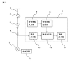
FIG. 1 is a schematic configuration diagram showing an installation state of a motor diagnostic device according to
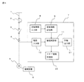
図1において、電力系統から引き込まれた主回路1には、配線用遮断器2と電磁接触器3および三相の主回路1の一相の負荷電流を検出する計器用変成器などの電流検出器4が設けられている。主回路1には負荷である三相誘導電動機などの電動機5が接続され、電動機5により機械設備6が運転駆動される。電動機の診断装置7には電源周波数や電動機5の定格出力、定格電圧、定格電流、極数、定格回転数等を予め入力しておく定格情報入力部8と、定格情報入力部8から入力された定格情報を保存しておく定格情報記憶部9が設けられている。定格情報は、電動機5の製造会社のカタログまたは電動機5に取付けられている銘板を見ることで容易に取得可能な情報である。なお、診断対象の電動機5が複数台ある場合には、予め全ての診断対象の電動機5の定格情報を入力しておくが、以降の説明においては1台の電動機5について説明する。また、電動機の診断装置7には、電流検出器4で検出された電流を入力する電流入力部10と、電流入力部10から入力された電流を使用して電動機5の異常の有無を診断する論理演算部11と、論理演算部11で異常が発見された場合に警報または異常ランプの点灯等によって警報を出力する警報出力部21が設けられている。
In FIG. 1, the
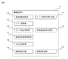
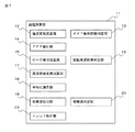
論理演算部11の構成について図2にもとづき説明する。論理演算部11は、電流入力部10から入力された電流の変動有無を求める電流変動演算部12と、電流変動演算部12で求められた結果を使用して電流の安定した区間を抽出してパワースペクトル解析区間を決定するFFT解析区間判定部13と、FFT解析区間判定部13で決定された区間の電流を使用してパワースペクトル解析を実施するFFT解析部14と、FFT解析部14で解析されたパワースペクトルに含まれるピーク箇所を検出するピーク検出演算部15と、ピーク検出演算部15で検出されたピーク箇所から回転周波数に起因するピーク箇所を求める回転周波数帯判定部16と、複数回分のパワースペクトルの回転周波数帯の周波数を合わせる周波数軸変換演算部17と、周波数軸変換演算部17で周波数軸が変換された複数回分のパワースペクトルを平均化処理する平均化演算部18と、平均化演算部18で平均化されたパワースペクトルを使用して回転周波数帯以外に電源周波数の両側にピーク箇所があるかを抽出する(以下、このピーク箇所を側帯波と称す)側帯波抽出部19と、側帯波抽出部19で側帯波が抽出されたとき側帯波の信号強度が設定値以上か判定する側帯波判定部20によって構成されている。
The configuration of the
電流変動演算部12は、電流入力部10からの電流を基に電流値の統計的なばらつきを演算する。ばらつきの演算は、例えば標準偏差やマハラノビス距離等の手法がある。
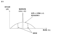
FFT解析区間判定部13は、電流変動演算部12で求めた電流値の統計的なばらつきから、ばらつきがしきい値以下の電流値が安定した状態の電流区間のみを抽出してパワースペクトル解析区間を決定する。一般に電動機5の負荷トルクが変動していると電流値にばらつきが生じて、ばらつきの大きい電流波形のパワースペクトル解析を実施すると、図3に示すように電源周波数の近傍両側の信号強度が増大して、側帯波などのピーク箇所が出現しなくなる。これを防止するためにFFT解析区間判定部13のしきい値が設けられている。
The current
The FFT analysis
FFT解析部14は、FFT解析区間判定部13で決定された区間に入力された電流波形を使用して周波数解析を行うことにより電流パワースペクトル強度を算出する。電流値が安定した状態の電流波形でパワースペクトル解析を実施することで、電源周波数の近傍両側でパワースペクトル強度が増加することは無くなり、ピーク箇所があれば確実に出現するようになる。
ピーク検出演算部15は、電流パワースペクトル強度の解析結果から電源周波数によるピーク箇所と回転周波数によるピーク箇所と側帯波によるピーク箇所およびその他のピーク箇所を検出する。ピーク箇所の検出は1次と2次と3次の微分計算によって算出した結果の急峻な傾きが反転する部分を抽出することで検出可能である。微分計算を3次まで実施することによって、より小さい信号強度のピーク箇所の検出が可能となる。電源周波数によるピーク箇所は、定格情報記憶部9に保存されている電源周波数(一般に50Hzまたは60Hz)の位置に生じるため簡単に確認できる。
The
The peak
回転周波数帯判定部16は、定格情報記憶部9に保存されている定格回転数から回転周波数を求め、電源周波数を中心として両側に回転周波数分ずれた位置付近にある信号強度が同様なピーク箇所を抽出する。一般に電動機5は負荷トルクの状況に応じてスベリが生じて回転数にずれが生じるため、回転周波数に起因するピーク箇所もその分ずれて出現する。回転周波数帯判定部16はこのずれを考慮した周波数帯内にあるピーク箇所を抽出して回転周波数帯として決定するものである。
The rotation frequency
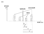
周波数軸変換演算部17は、平均化演算部18で実施する平均化演算を正しく行うために必要である。一般に電動機5の異常によって発生する側帯波の発生位置は回転周波数帯と関係が深く、側帯波の周波数帯は回転周波数帯の倍数であることが多い。また、回転周波数帯は上記説明のように、電動機5の負荷トルクの状況に応じてずれて出現する。このため、平均化対象の複数回分のパワースペクトル解析結果をピーク箇所追従方式で周波数軸を合わせておく必要がある。具体的には図4に示すように、回転周波数帯の周波数が電源周波数からfr離れた位置で側波帯の周波数が電源周波数からfb離れた位置であり、電動機5が無負荷の状態での回転周波数帯の周波数が電源周波数からfr´離れた位置であったとすると、変換率αはα=fr´/frとなり、無負荷時の側帯波の位置fb´はfb´=α・fbで求めることが出来る。このように回転周波数帯を基準として変換率αを掛けることにより全てのピーク箇所の周波数軸の変換を行う。なお、上記説明では周波数軸を無負荷時に合わせる場合について説明したが、例えば周波数軸を定格負荷時に合わせるなど、周波数軸変換演算部17は平均化対象の複数回分のパワースペクトル解析結果の周波数軸を所定の負荷時に合わせるように構成されていればよい。
The frequency axis
平均化演算部18は、周波数軸変換演算部17で周波数軸が合わされた複数回分のパワースペクトル解析結果を平均化処理するもので、平均化処理することで基底ノイズを低減させてピーク箇所のS/N比を向上させることが出来る。具体的には10回分のパワースペクトル解析結果を平均化処理すると、1回分にしか発生していないノイズ等によるピーク箇所は10分の1の信号強度に低減されることになる。一方、回転周波数帯や側帯波であれば10回ともピーク箇所が発生するものであり、ピーク追従方式で周波数軸を変換して周波数が合っているため、平均化してもピーク箇所の信号強度は変化しない。なお、上記説明ではパワースペクトル解析結果の10回分を平均化する場合について説明したが、10回に限定されるものではなく複数回分を平均化すればよい。
The averaging
側帯波抽出部19は、平均化演算部18で平均化処理されたパワースペクトル解析結果から電源周波数を中心として両側に同一周波数ずれた位置に発生しているピーク箇所を側帯波として抽出する。側帯波の候補はピーク検出演算部15で得られたピーク箇所を候補として選択する。電源周波数を中心としてピーク箇所が片側にしか発生していない場合には側帯波ではないと判定して抽出しない。
側帯波判定部20は、側帯波抽出部19で抽出された側帯波の個数と信号強度から電動機5が異常か否かを判定する。電動機5が異常であると判定した場合には、警報出力部21から警報を出力する。
The sideband
The sideband
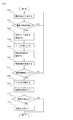
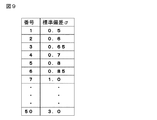
次に動作について図5にもとづき説明する。電動機の診断装置7は所定時間間隔で起動されて以下の処理を実行する。ステップ101において、電流検出器4で検出した電動機5の電流を電流入力部10で入力する。ステップ102において、電流入力部10から入力された電流の実効値(以下、電流値と称す)のばらつきを電流変動演算部12で演算して、その演算結果を使用してFFT解析区間判定部13で電流が安定状態であるか判定する。判定結果として電流値のばらつきが予め設定されているしきい値以上の不安定状態(NO)であればステップ101に戻り、電流が安定状態になるまで繰り返す。電流が安定状態(YES)であればステップ103に進む。なお、しきい値に関しては、例えば、事前に複数のモータのフィールドデータを取得し、そのデータの電流ばらつき値(標準偏差)から、ばらつき値の小さい範囲内を選定し、選定した値をしきい値とする。具体的な計算例としては、例えば図9に示すように、50回ばらつき値を計算して、小さい順に並べ替えた中で5番目に小さいばらつき値である0.8をしきい値として決定する。なお、事前のフィールドデータの代わりに、電動機5にて一定の学習期間を設けて、学習期間中に取得した電流ばらつき値(標準偏差)から、同様に算出してもよい。
Next, the operation will be described with reference to FIG. The electric
ステップ103において、FFT解析部14は入力された電流値が安定状態の区間の電流波形を使用して0Hzから電源周波数60Hzの2倍の周波数120Hzの間で周波数分析して、そのパワースペクトル解析結果をピーク検出演算部15に渡す。ステップ104において、ピーク検出演算部15はパワースペクトル解析結果に含まれるピーク箇所を全て検出する。ステップ105において、回転周波数帯判定部16は検出されたピーク箇所の内で回転周波数帯にあるピーク箇所を抽出して回転周波数帯を決定する。ステップ106において、周波数軸変換演算部17は検出した回転周波数帯を無負荷時の回転周波数帯になるように全てのピーク箇所の周波数軸を変換する。ステップ107において、ステップ101からステップ106の動作を10回繰り返して、周波数軸が変換されたパワースペクトル解析結果を10個収集する。
In
ステップ108において、平均化演算部18は収集された10個のパワースペクトル解析結果を平均化処理する。ステップ109において、側帯波抽出部19は平均化処理されたパワースペクトル解析結果のピーク箇所に注目して側帯波を抽出する。ステップ110において、側帯波判定部20は側帯波抽出部19で側帯波が抽出されなかった場合または側帯波が抽出されたが設定値よりも小さい信号強度であった場合には、電動機5に異常は発生していない(NO)として診断処理を終了する。一方、側帯波抽出部19で抽出された側帯波の信号強度が設定値よりも大きい場合(YES)には、電動機5に異常が発生しているとして警報出力部21に信号を送り、ステップ111において、警報出力部21から警報を出力して診断処理を終了する。なお、側帯波判定部20の設定値については、正常時の側帯波の信号強度Aを学習させ、標準偏差σを計算し、検出された側帯波ピーク値が、A+3σである99.7%のデータが存在する範囲を設定値とする。もしくは、安全係数α(例えば2以上)を掛けて、A+3σ×αとしてもよい。また、上記の設定値の別の決め方としては、同様の電動機の過去の故障時のデータ等から決められるものであり、故障事例が多くなるほど側帯波によって正確な故障場所や故障の程度を判定できるようになる。
In
以上説明したように、電流値が安定しているときの電流波形をパワースペクトル解析することで、側帯波などのピーク箇所が確実に出現する。また、平均化処理を実施することでノイズ等が低減されて、より正確な故障診断が出来るようになる。 As described above, a peak portion such as a sideband appears surely by analyzing the power spectrum of the current waveform when the current value is stable. Further, by performing the averaging process, noise and the like are reduced, and a more accurate failure diagnosis can be performed.
実施の形態2.
図6はこの発明の実施の形態2における電動機の診断装置の設置状況を示す概略構成図、図7はこの発明の実施の形態2における電動機の診断装置の論理演算部の構成を示すブロック図、図8はこの発明の実施の形態2における電動機の診断装置のトレンド解析を説明する説明図である。上記実施の形態1では、平均化処理されたパワースペクトル解析結果を使用して電動機5の異常を診断する場合について説明したが、実施の形態2では平均化処理されたパワースペクトル解析結果を時系列に保存しておいてトレンド監視を行う場合について説明する。
FIG. 6 is a schematic configuration diagram showing the installation status of the motor diagnostic device according to
図6において、電動機の診断装置7には平均化処理されたパワースペクトル解析結果を時系列で保存するFFT情報記憶部22が設けられており、図7に示すように、論理演算部11にトレンド解析部23が設けられている。
In FIG. 6, the
次に、トレンド解析部23の動作について説明する。トレンド解析部23は、FFT情報記憶部22に時系列で保存されているパワースペクトル解析結果の特定の周波数の側帯波に着目して、その側帯波の信号強度を図8に示すように時系列に求めて表示するものである。図8における設定値は、側帯波判定部20で使用される設定値である。このようにトレンド解析を行うことで、例えば側帯波が電動機5の軸受の摩耗によって生じたものであったとすると、側帯波の信号強度が小さい場合には軸受の摩耗の程度が小さく異常とはならないが、軸受の摩耗は徐々に増加するため、側帯波の信号強度も図8に示すように時系列で徐々に増加していく。従って、側帯波の信号強度が設定値に到達して軸受交換が必要となる時期がトレンド解析を実施することで分かることとなる。なお、他の部分については実施の形態1と同様であるため説明を省略する。
Next, the operation of the
なお、この発明は、その発明の範囲内において各実施の形態を自由に組み合わせたり、実施の形態を適宜、変形、省略することが可能である。 In the present invention, the embodiments can be freely combined within the scope of the invention, and the embodiments can be appropriately modified and omitted.
1 主回路、2 配線用遮断器、3 電磁接触器、4 電流検出器、5 電動機、6 機械設備、7 電動機の診断装置、8 定格情報入力部、9 定格情報記憶部、10 電流入力部、11 論理演算部、12 電流変動演算部、13 FFT解析区間判定部、14 FFT解析部、15 ピーク検出演算部、16 回転周波数帯判定部、17 周波数軸変換演算部、18 平均化演算部、19 側帯波抽出部、20 側帯波判定部、21 警報出力部、22 FFT情報記憶部、23 トレンド解析部
DESCRIPTION OF
Claims (3)
Priority Applications (1)
| Application Number | Priority Date | Filing Date | Title |
|---|---|---|---|
| JP2015075583A JP6190841B2 (en) | 2015-04-02 | 2015-04-02 | Diagnostic equipment for electric motors |
Applications Claiming Priority (1)
| Application Number | Priority Date | Filing Date | Title |
|---|---|---|---|
| JP2015075583A JP6190841B2 (en) | 2015-04-02 | 2015-04-02 | Diagnostic equipment for electric motors |
Publications (3)
| Publication Number | Publication Date |
|---|---|
| JP2016195524A JP2016195524A (en) | 2016-11-17 |
| JP2016195524A5 JP2016195524A5 (en) | 2017-02-16 |
| JP6190841B2 true JP6190841B2 (en) | 2017-08-30 |
Family
ID=57323135
Family Applications (1)
| Application Number | Title | Priority Date | Filing Date |
|---|---|---|---|
| JP2015075583A Active JP6190841B2 (en) | 2015-04-02 | 2015-04-02 | Diagnostic equipment for electric motors |
Country Status (1)
| Country | Link |
|---|---|
| JP (1) | JP6190841B2 (en) |
Cited By (2)
| Publication number | Priority date | Publication date | Assignee | Title |
|---|---|---|---|---|
| US10883895B2 (en) | 2016-12-15 | 2021-01-05 | Mitsubishi Electric Corporation | Abnormality diagnostic device for power transmission mechanism and abnormality diagnostic method for power transmission mechanism |
| DE112020007232T5 (en) | 2020-05-25 | 2023-03-16 | Mitsubishi Electric Corporation | ENGINE DIAGNOSTIC DEVICE |
Families Citing this family (13)
| Publication number | Priority date | Publication date | Assignee | Title |
|---|---|---|---|---|
| CN110268623B (en) * | 2017-02-03 | 2022-08-05 | 三菱电机株式会社 | Diagnostic device for motor |
| EP3648338B1 (en) * | 2017-06-29 | 2022-02-16 | Mitsubishi Electric Corporation | Diagnostic device for electric motor |
| JP6818155B2 (en) | 2017-09-05 | 2021-01-20 | 株式会社日立製作所 | AC motor monitoring device and monitoring method, and motor drive system monitoring device and monitoring method |
| KR101950385B1 (en) * | 2017-09-12 | 2019-02-20 | 주식회사 파워스캔 | System and method for diagnosing induction motor and load, and a recording medium having computer readable program for executing the method |
| EP3716469B1 (en) | 2017-11-22 | 2025-04-30 | Mitsubishi Electric Corporation | DIAGNOSTIC DEVICE FOR EQUIPMENT WEAR |
| JP7457452B2 (en) * | 2018-06-07 | 2024-03-28 | 三菱重工業株式会社 | Control device, control system, control method and control program |
| JP7059161B2 (en) | 2018-10-22 | 2022-04-25 | 株式会社日立製作所 | Rotating machine diagnostic system |
| JPWO2020137362A1 (en) * | 2018-12-26 | 2021-11-11 | 日本電産株式会社 | Judgment device, motor device and program |
| JP7198089B2 (en) * | 2019-01-10 | 2022-12-28 | 株式会社日立産機システム | POWER CONVERTER, ROTATING MACHINE SYSTEM, AND DIAGNOSTIC METHOD |
| JP7594434B2 (en) * | 2020-01-16 | 2024-12-04 | 株式会社日立産機システム | POWER CONVERSION DEVICE, ROTATING MACHINE SYSTEM, AND DIAGNOSIS METHOD |
| JP7340482B2 (en) | 2020-03-03 | 2023-09-07 | 株式会社日立製作所 | Equipment monitoring device and equipment monitoring method |
| CN114720872A (en) * | 2022-03-24 | 2022-07-08 | 深圳市双合电气股份有限公司 | Fault diagnosis method and system for motor load transmission mechanism |
| WO2025224993A1 (en) * | 2024-04-26 | 2025-10-30 | 三菱電機株式会社 | Diagnostic device for electric motor and diagnostic system for electric motor |
Family Cites Families (3)
| Publication number | Priority date | Publication date | Assignee | Title |
|---|---|---|---|---|
| JP4062939B2 (en) * | 2002-03-14 | 2008-03-19 | Jfeスチール株式会社 | Rotor abnormality detection method and rotor abnormality detection apparatus for AC motor |
| JP5565120B2 (en) * | 2010-06-09 | 2014-08-06 | 富士電機株式会社 | High-frequency electromagnetic vibration component removal method and high-frequency electromagnetic vibration component removal device, rolling bearing diagnosis method and bearing diagnosis device for a rotating machine |
| EP2518456A1 (en) * | 2011-04-29 | 2012-10-31 | ABB Technology AG | Method for monitoring demagnetization |
-
2015
- 2015-04-02 JP JP2015075583A patent/JP6190841B2/en active Active
Cited By (2)
| Publication number | Priority date | Publication date | Assignee | Title |
|---|---|---|---|---|
| US10883895B2 (en) | 2016-12-15 | 2021-01-05 | Mitsubishi Electric Corporation | Abnormality diagnostic device for power transmission mechanism and abnormality diagnostic method for power transmission mechanism |
| DE112020007232T5 (en) | 2020-05-25 | 2023-03-16 | Mitsubishi Electric Corporation | ENGINE DIAGNOSTIC DEVICE |
Also Published As
| Publication number | Publication date |
|---|---|
| JP2016195524A (en) | 2016-11-17 |
Similar Documents
| Publication | Publication Date | Title |
|---|---|---|
| JP6190841B2 (en) | Diagnostic equipment for electric motors | |
| JP6293388B1 (en) | Load abnormality detection device | |
| WO2018020563A1 (en) | Electric motor diagnosis device | |
| JP6316510B1 (en) | Diagnostic equipment for electric motors | |
| JP7046064B2 (en) | Diagnostic device for motors | |
| KR102875507B1 (en) | Abnormal diagnosis device and abnormal diagnosis method | |
| KR102427372B1 (en) | Abnormality diagnosis device, abnormality diagnosis method, and abnormality diagnosis system | |
| JP7361881B2 (en) | Electric motor diagnostic equipment | |
| KR102104117B1 (en) | Diagnostic device of electric motor | |
| JP6824493B1 (en) | Diagnostic device for electric motor | |
| JP7422896B2 (en) | Electric motor diagnostic equipment | |
| KR20250048104A (en) | Device for diagnosing the condition of an electric motor, method for diagnosing the condition, and device for inferring abnormalities |
Legal Events
| Date | Code | Title | Description |
|---|---|---|---|
| A521 | Request for written amendment filed |
Free format text: JAPANESE INTERMEDIATE CODE: A523 Effective date: 20170116 |
|
| A621 | Written request for application examination |
Free format text: JAPANESE INTERMEDIATE CODE: A621 Effective date: 20170116 |
|
| A871 | Explanation of circumstances concerning accelerated examination |
Free format text: JAPANESE INTERMEDIATE CODE: A871 Effective date: 20170116 |
|
| A975 | Report on accelerated examination |
Free format text: JAPANESE INTERMEDIATE CODE: A971005 Effective date: 20170301 |
|
| A131 | Notification of reasons for refusal |
Free format text: JAPANESE INTERMEDIATE CODE: A131 Effective date: 20170411 |
|
| A521 | Request for written amendment filed |
Free format text: JAPANESE INTERMEDIATE CODE: A523 Effective date: 20170516 |
|
| TRDD | Decision of grant or rejection written | ||
| A01 | Written decision to grant a patent or to grant a registration (utility model) |
Free format text: JAPANESE INTERMEDIATE CODE: A01 Effective date: 20170711 |
|
| A61 | First payment of annual fees (during grant procedure) |
Free format text: JAPANESE INTERMEDIATE CODE: A61 Effective date: 20170807 |
|
| R151 | Written notification of patent or utility model registration |
Ref document number: 6190841 Country of ref document: JP Free format text: JAPANESE INTERMEDIATE CODE: R151 |
|
| R250 | Receipt of annual fees |
Free format text: JAPANESE INTERMEDIATE CODE: R250 |
|
| R250 | Receipt of annual fees |
Free format text: JAPANESE INTERMEDIATE CODE: R250 |
|
| R250 | Receipt of annual fees |
Free format text: JAPANESE INTERMEDIATE CODE: R250 |
|
| R250 | Receipt of annual fees |
Free format text: JAPANESE INTERMEDIATE CODE: R250 |
|
| R250 | Receipt of annual fees |
Free format text: JAPANESE INTERMEDIATE CODE: R250 |
|
| R250 | Receipt of annual fees |
Free format text: JAPANESE INTERMEDIATE CODE: R250 |