EP3680729B1 - Fond orientable pour une piece d'horlogerie - Google Patents
Fond orientable pour une piece d'horlogerie Download PDFInfo
- Publication number
- EP3680729B1 EP3680729B1 EP19151038.7A EP19151038A EP3680729B1 EP 3680729 B1 EP3680729 B1 EP 3680729B1 EP 19151038 A EP19151038 A EP 19151038A EP 3680729 B1 EP3680729 B1 EP 3680729B1
- Authority
- EP
- European Patent Office
- Prior art keywords
- watch case
- annular
- case
- braking means
- watch
- Prior art date
- Legal status (The legal status is an assumption and is not a legal conclusion. Google has not performed a legal analysis and makes no representation as to the accuracy of the status listed.)
- Active
Links
- 230000000295 complement effect Effects 0.000 claims description 5
- 239000000463 material Substances 0.000 claims description 5
- 238000007789 sealing Methods 0.000 claims 1
- 239000011521 glass Substances 0.000 description 2
- 238000012986 modification Methods 0.000 description 2
- 230000004048 modification Effects 0.000 description 2
- 210000000707 wrist Anatomy 0.000 description 2
- 241000920340 Pion Species 0.000 description 1
- 239000000919 ceramic Substances 0.000 description 1
- 239000002131 composite material Substances 0.000 description 1
- 230000006835 compression Effects 0.000 description 1
- 238000007906 compression Methods 0.000 description 1
- 210000002858 crystal cell Anatomy 0.000 description 1
- 230000007547 defect Effects 0.000 description 1
- 210000004247 hand Anatomy 0.000 description 1
- 239000004973 liquid crystal related substance Substances 0.000 description 1
- 238000003754 machining Methods 0.000 description 1
- 238000004519 manufacturing process Methods 0.000 description 1
- 229910052751 metal Inorganic materials 0.000 description 1
- 239000002184 metal Substances 0.000 description 1
- 229910001092 metal group alloy Inorganic materials 0.000 description 1
- 150000002739 metals Chemical class 0.000 description 1
- 239000000758 substrate Substances 0.000 description 1
Images


Classifications
-
- G—PHYSICS
- G04—HOROLOGY
- G04B—MECHANICALLY-DRIVEN CLOCKS OR WATCHES; MECHANICAL PARTS OF CLOCKS OR WATCHES IN GENERAL; TIME PIECES USING THE POSITION OF THE SUN, MOON OR STARS
- G04B45/00—Time pieces of which the indicating means or cases provoke special effects, e.g. aesthetic effects
- G04B45/0084—Pictures or inscriptions on the case or parts thereof, attaching complete pictures
-
- G—PHYSICS
- G04—HOROLOGY
- G04B—MECHANICALLY-DRIVEN CLOCKS OR WATCHES; MECHANICAL PARTS OF CLOCKS OR WATCHES IN GENERAL; TIME PIECES USING THE POSITION OF THE SUN, MOON OR STARS
- G04B37/00—Cases
- G04B37/0008—Cases for pocket watches and wrist watches
-
- G—PHYSICS
- G04—HOROLOGY
- G04B—MECHANICALLY-DRIVEN CLOCKS OR WATCHES; MECHANICAL PARTS OF CLOCKS OR WATCHES IN GENERAL; TIME PIECES USING THE POSITION OF THE SUN, MOON OR STARS
- G04B37/00—Cases
- G04B37/12—Cases for special purposes, e.g. watch combined with ring, watch combined with button
-
- G—PHYSICS
- G04—HOROLOGY
- G04B—MECHANICALLY-DRIVEN CLOCKS OR WATCHES; MECHANICAL PARTS OF CLOCKS OR WATCHES IN GENERAL; TIME PIECES USING THE POSITION OF THE SUN, MOON OR STARS
- G04B19/00—Indicating the time by visual means
- G04B19/28—Adjustable guide marks or pointers for indicating determined points of time
- G04B19/283—Adjustable guide marks or pointers for indicating determined points of time on rotatable rings, i.e. bezel
- G04B19/286—Adjustable guide marks or pointers for indicating determined points of time on rotatable rings, i.e. bezel with locking means to prevent undesired rotations in both directions
-
- G—PHYSICS
- G04—HOROLOGY
- G04B—MECHANICALLY-DRIVEN CLOCKS OR WATCHES; MECHANICAL PARTS OF CLOCKS OR WATCHES IN GENERAL; TIME PIECES USING THE POSITION OF THE SUN, MOON OR STARS
- G04B37/00—Cases
- G04B37/08—Hermetic sealing of openings, joints, passages or slits
- G04B37/11—Hermetic sealing of openings, joints, passages or slits of the back cover of pocket or wrist watches
-
- G—PHYSICS
- G04—HOROLOGY
- G04B—MECHANICALLY-DRIVEN CLOCKS OR WATCHES; MECHANICAL PARTS OF CLOCKS OR WATCHES IN GENERAL; TIME PIECES USING THE POSITION OF THE SUN, MOON OR STARS
- G04B45/00—Time pieces of which the indicating means or cases provoke special effects, e.g. aesthetic effects
- G04B45/0084—Pictures or inscriptions on the case or parts thereof, attaching complete pictures
- G04B45/0092—Changeable parts
-
- G—PHYSICS
- G04—HOROLOGY
- G04B—MECHANICALLY-DRIVEN CLOCKS OR WATCHES; MECHANICAL PARTS OF CLOCKS OR WATCHES IN GENERAL; TIME PIECES USING THE POSITION OF THE SUN, MOON OR STARS
- G04B37/00—Cases
- G04B37/0075—Cases with means to enhance sound transmission
Definitions
- the present invention relates to bases for timepieces and more particularly to such bases comprising a pattern or a logo on their external face and in which said pattern or logo can be oriented as desired.
- the documents EP 1 890 203 A1 And US 5,923,622 A describe a base for a watch case, the base comprising a first element arranged to be screwed onto the watch case, and a second element comprising an end face bearing a pattern, the second element being mounted movable in rotation around a axis passing through the center of the box, where the second element comprises braking means arranged to maintain it relative to the first element in different angular positions around the axis of rotation, the braking means being arranged between the first and second elements.
- the present invention which is defined by appended claim 1, aims to remedy this drawback as well as others by proposing a system allowing, after screwing a back onto the middle of a watch case , to adjust in a simple and effective manner the orientation of the back in relation to the watch, so as to guarantee a suitable arrangement of the inscriptions and other decorative motifs which have been transferred to the face of the back of the watch directed towards the wrist of the watch. wearer of this watch.
- the present invention relates to a base for a watch case, the base comprising a first element arranged to be screwed onto the watch case, and a second element comprising an end face bearing a pattern, the second element being mounted movable in rotation around an axis passing through the center of the box, characterized in that the second element comprises braking means arranged to maintain it relative to the first element in different angular positions around the axis of rotation, the braking means being arranged between the first and second elements.
- the present invention provides a device for fixing a watch case back which allows this base to be completely screwed onto the middle of the watch so as to ensure the watertightness of the latter and to avoid as much as possible any risk of losing said back, then, although the back is screwed tightly, to pivot a movable element of this back in relation to the middle part to compensate for any possible misalignment of the inscriptions or patterns applied to the visible face of said back .
- the invention also relates to a timepiece comprising a base conforming to the invention.
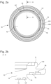
- FIG. 1 illustrates a back 1 for a watch case 50 intended to be screwed by a screw thread onto a middle part 51, the latter having a complementary thread machined at its base and on its inner periphery.
- the back 1 comprises a first element 10 arranged to be screwed onto the watch case 50, and a second element 20 comprising an end face 21 bearing a pattern such as a logo or a brand, the second element 20 being mounted movable in rotation around an axis passing through the center of the watch case.
- the first element 10 is intended to be screwed onto the watch case 50 and has for this purpose, on its rear face, that is to say the face facing the inside of the case, an annular shoulder 11 comprising a thread 110 on its outer perimeter.
- the shoulder 11 is screwed to the base of the watch case 50 which includes a complementary thread provided for this purpose.
- the first element 10 also comprises, on its front face, that is to say the face facing the outside of the box, a base 12 with an inclined wall 13 towards the outside of the box so that said base 12 has a cross-section of substantially trapezoidal shape.
- the second element 20 comprises a cavity 22 with an inclined wall 23 complementary to the base 12 to be able to carry out clipping (clipping) or interlocking by force, and thus assemble the two elements 10, 20.
- clipping clipping
- the edges of the base 12 and the cavity 22 are chamfered.
- the base 12 of the first element 10 comprises hollowed-out portions 13' and an annular groove 13" formed behind the wall 13 so as to facilitate the deformation of the wall during the forceful nesting of the second element 20 onto the first element.
- the diameter of the base 12 and the cavity 22 are less than the diameters of the first and second elements 10, 20.
- the second element 20 is rotatably mounted on the first element 10 around the axis of rotation C passing through the center of the box 100, the interlocking or clipping providing sufficient clearance to rotate the second element 20.
- the first element 10 successively comprises a first annular groove 14 formed in the base 12, an annular groove 15 formed near the periphery of the first element and a second annular groove 16 also formed in the immediate vicinity of the periphery of the first element 10.
- the second element 20 has an orifice 24 arranged to receive a pin 25, the pin 25 cooperating with the annular groove 15 formed in the first element 10 so as to guide the second element 20 during its pivoting.
- the annular groove 15 is not continuous and has two ends 150 and 151 close to each other each defining a stop.
- braking means are provided which act preferably by friction and which according to the invention are arranged to maintain different orientations angular angles of the second element 20 relative to the first element 10, and therefore relative to the middle part.
- the second element bearing the pattern M can be easily moved angularly into a desired position against the friction force generated by the braking means and maintained in the desired position.
- the second element 20 is thus clamped axially between its rear face and the front face of the first element 10.
- the respective dimensions of the second element 20, in particular its thickness, and those of the first element 10 are chosen so that the edge of the second element 20 is flush with the front face of the first element 10 to thus form a continuous surface.
- the braking means comprise at least one elastic annular element 30 which in particular has elasticity in a direction parallel to the axis of rotation C.
- the annular element can be produced by a seal made of compressible material natural or synthetic.
- the annular element 30 is disposed between the first and the second element.
- the elastic annular element(s) 30 are arranged in the first and second annular grooves 14 and 16 which are formed in the front face of the first element.
- a person skilled in the art could, without particular difficulty, reverse this assembly and place the elastic annular elements 30 on the rear face of the second element 20 by forming the grooves 14 and 16 there beforehand.
- the annular grooves 14 and 16 are arranged on either side of the annular groove 15, which allows better distribution of the friction forces generated by the elastic annular elements 30.
- the second annular groove 16 has two levels: a first level forming the bottom of the groove arranged to receive an elastic annular element 30, and a second level forming the opening of the groove arranged to receive the edge of the second element 20.
- the second level has dimensions greater than the first level of such that the edge of the second element 20 can move in translation in the direction of the axis C.
- the desired braking force can be controlled by adapting the compression rate of the annular element during manufacturing.
- the manufacturer exerts pressure on the second element 20 towards the watch case so as to compress the elastic annular elements 30. Then, while maintaining the pressure on the second element, the manufacturer rotates the second element relative to the first element 10 so as to orient the back in a desired angular position so that the pattern M is, for example, aligned with the axis 6H-12H of the watch.
- the second element 20 comprises a notch 26 capable of receiving a tool to exert a lever force and thus dislodge the second element.
- the timepiece 100 for example of the wristwatch type, which is provided with the back 1 according to the invention is partially shown on the figure 1 .
- This timepiece includes in particular a middle part 51 surmounted by a bezel 52 which can be screwed onto the middle part 51 and which serves to hold a glass 53.
- the assembly formed by the bezel 52 and the glass 53 is made watertight by interposition of a joint 54.
- the middle part 51 also has a hole for the passage of a rod 55 on which a crown 56 is fixed.
- the wristwatch is of the type with an analog display of the hour and for this purpose includes a set of hands 58 for hours and minutes (only one hand has been shown in the drawing) moving above a dial 57. It goes without saying that the present invention could just as easily be applied to a watch with a digital time display comprising, for example, a liquid crystal cell .
- an O-ring 31 is conventionally inserted into an annular groove 59 made at the base of the middle part 51 to guarantee the seal between the first element 10 of the bottom 1 and said middle part 51.
- the first and second elements can be made of metals, of a metal alloy, of ceramic, of a composite material or even of a plastic material.
Landscapes
- Physics & Mathematics (AREA)
- General Physics & Mathematics (AREA)
- Electric Clocks (AREA)
Priority Applications (4)
| Application Number | Priority Date | Filing Date | Title |
|---|---|---|---|
| EP19151038.7A EP3680729B1 (fr) | 2019-01-09 | 2019-01-09 | Fond orientable pour une piece d'horlogerie |
| JP2019233841A JP6868088B2 (ja) | 2019-01-09 | 2019-12-25 | 計時器のための向きを調整可能な裏蓋 |
| US16/735,948 US11698607B2 (en) | 2019-01-09 | 2020-01-07 | Orientable back for a timepiece |
| CN202010017655.5A CN111427251B (zh) | 2019-01-09 | 2020-01-08 | 钟表的可定向后盖 |
Applications Claiming Priority (1)
| Application Number | Priority Date | Filing Date | Title |
|---|---|---|---|
| EP19151038.7A EP3680729B1 (fr) | 2019-01-09 | 2019-01-09 | Fond orientable pour une piece d'horlogerie |
Publications (2)
| Publication Number | Publication Date |
|---|---|
| EP3680729A1 EP3680729A1 (fr) | 2020-07-15 |
| EP3680729B1 true EP3680729B1 (fr) | 2024-04-24 |
Family
ID=65011927
Family Applications (1)
| Application Number | Title | Priority Date | Filing Date |
|---|---|---|---|
| EP19151038.7A Active EP3680729B1 (fr) | 2019-01-09 | 2019-01-09 | Fond orientable pour une piece d'horlogerie |
Country Status (4)
| Country | Link |
|---|---|
| US (1) | US11698607B2 (ja) |
| EP (1) | EP3680729B1 (ja) |
| JP (1) | JP6868088B2 (ja) |
| CN (1) | CN111427251B (ja) |
Families Citing this family (2)
| Publication number | Priority date | Publication date | Assignee | Title |
|---|---|---|---|---|
| EP3958067A1 (fr) * | 2020-08-17 | 2022-02-23 | The Swatch Group Research and Development Ltd | Dispositif de fixation d'un fond sur une carrure pour piece d'horlogerie |
| EP4194967A1 (fr) * | 2021-12-07 | 2023-06-14 | The Swatch Group Research and Development Ltd | Dispositif de fixation d'un fond sur une carrure pour piece d'horlogerie |
Family Cites Families (14)
| Publication number | Priority date | Publication date | Assignee | Title |
|---|---|---|---|---|
| CH243389A (fr) * | 1945-05-12 | 1946-07-15 | Luthy Edouard | Boîte de montre étanche. |
| JPH11118954A (ja) | 1997-10-08 | 1999-04-30 | Seiko Epson Corp | 部材取付装置、部材取付装置を有する時計、及び部材取付装置を有する電子機器 |
| JP3243443B2 (ja) * | 1998-02-09 | 2002-01-07 | 理得國際企業有限公司 | 腕時計底蓋の結合構造 |
| ATE389199T1 (de) * | 2001-07-18 | 2008-03-15 | Swatch Group Man Serv Ag | Vorrichtung zur verstellung der ausrichtung eines bodens, der auf das mittelteil eines uhrgehäuses geschraubt ist, in bezug auf eine achse 12h-6h |
| DE602004027370D1 (de) | 2004-08-13 | 2010-07-08 | Swatch Group Man Serv Ag | Uhr mit Lichtleiternuhrenglas |
| US7324410B1 (en) * | 2005-07-25 | 2008-01-29 | Amir Ziv | Watch with special back |
| EP1760556A1 (fr) * | 2005-09-06 | 2007-03-07 | The Swatch Group Management Services AG | Dispositif de fixation d'un fond sur une carrure d'une montre |
| EP1890203B1 (fr) | 2006-08-17 | 2012-08-01 | Omega SA | Boîte de montre comprenant un fond et procédé de fixation d'un fond sur une boîte de montre |
| JP2010127683A (ja) * | 2008-11-26 | 2010-06-10 | Seiko Instruments Inc | 携帯時計 |
| CH705089A2 (fr) * | 2011-06-08 | 2012-12-14 | Omega Sa | Dispositif et procédé de fixation d'un élément de montre avec orientation angulaire réglable. |
| JP6364763B2 (ja) | 2013-12-20 | 2018-08-01 | カシオ計算機株式会社 | ケース、及び時計 |
| EP2952975B1 (fr) | 2014-06-03 | 2019-04-24 | The Swatch Group Research and Development Ltd | Dispositif d'assemblage d'un cercle d'encageage dans une carrure de montre |
| KR102359245B1 (ko) * | 2016-07-08 | 2022-02-04 | 가부시키가이샤 한도오따이 에네루기 켄큐쇼 | 전자 기기 |
| CH712740B1 (fr) * | 2016-07-26 | 2020-08-31 | Omega Sa | Sous-ensemble d'habillage pour pièce d'horlogerie, notamment une montre, ou pour bijou. |
-
2019
- 2019-01-09 EP EP19151038.7A patent/EP3680729B1/fr active Active
- 2019-12-25 JP JP2019233841A patent/JP6868088B2/ja active Active
-
2020
- 2020-01-07 US US16/735,948 patent/US11698607B2/en active Active
- 2020-01-08 CN CN202010017655.5A patent/CN111427251B/zh active Active
Also Published As
| Publication number | Publication date |
|---|---|
| US20200218201A1 (en) | 2020-07-09 |
| CN111427251A (zh) | 2020-07-17 |
| JP2020112550A (ja) | 2020-07-27 |
| EP3680729A1 (fr) | 2020-07-15 |
| JP6868088B2 (ja) | 2021-05-12 |
| CN111427251B (zh) | 2022-10-11 |
| US11698607B2 (en) | 2023-07-11 |
Similar Documents
| Publication | Publication Date | Title |
|---|---|---|
| EP1890203B1 (fr) | Boîte de montre comprenant un fond et procédé de fixation d'un fond sur une boîte de montre | |
| CA1309604C (fr) | Tete de cle et cle pourvue d'une telle tete | |
| EP0150746A2 (fr) | Boîte de montre | |
| EP1278108A1 (fr) | Dispositif de réglage de l'alignement d'un fond se vissant sur la carrure d'une boíte de montre par rapport à un axe 12H-6H | |
| EP3680729B1 (fr) | Fond orientable pour une piece d'horlogerie | |
| EP0873543A1 (fr) | Boite de montre comportant une enveloppe et un dispositif de support | |
| EP0443366A1 (fr) | Boîte de montre comportant deux coquilles jointives | |
| EP3540523B1 (fr) | Montre comprenant une boite de montre munie de deux cadrans | |
| WO2016023695A1 (fr) | Boite de montre munie d'un element d'habillage | |
| EP2533111A1 (fr) | Dispositif et procédé de fixation d'un élément de montre avec orientation angulaire réglable | |
| EP1388028B1 (fr) | Piece d'horlogerie munie d'un cadran interchangeable | |
| CH715720A2 (fr) | Fond orientable pour une pièce d'horlogerie. | |
| EP4176755A1 (fr) | Assemblage d'un brin de bracelet sur une boîte de montre | |
| EP3779606B1 (fr) | Montre à remontage automatique | |
| EP1189117B1 (fr) | Montre-bracelet à boîtier réversible | |
| CH503306A (fr) | Boîte de montre | |
| EP3958069A1 (fr) | Boîte de montre munie d'un élément d'habillage | |
| CH696090A5 (fr) | Montre-bracelet à boîtier réversible. | |
| EP3839663A1 (fr) | Organe horloger pour boîte de pièce d'horlogerie ou pour pièce d'horlogerie | |
| EP4134756B1 (fr) | Fond orientable pour une piece d` horlogerie | |
| EP3712714B1 (fr) | Cadran pour une montre universelle | |
| CH716554B1 (fr) | Boîte de montre à lunette amovible. | |
| EP4250020A1 (fr) | Boîte de montre à lunette tournante | |
| WO2023078836A1 (fr) | Assemblage d'un brin de bracelet sur une boîte de montre | |
| EP3828643A1 (fr) | Cadran pour piece d'horlogerie |
Legal Events
| Date | Code | Title | Description |
|---|---|---|---|
| PUAI | Public reference made under article 153(3) epc to a published international application that has entered the european phase |
Free format text: ORIGINAL CODE: 0009012 |
|
| STAA | Information on the status of an ep patent application or granted ep patent |
Free format text: STATUS: THE APPLICATION HAS BEEN PUBLISHED |
|
| AK | Designated contracting states |
Kind code of ref document: A1 Designated state(s): AL AT BE BG CH CY CZ DE DK EE ES FI FR GB GR HR HU IE IS IT LI LT LU LV MC MK MT NL NO PL PT RO RS SE SI SK SM TR |
|
| AX | Request for extension of the european patent |
Extension state: BA ME |
|
| STAA | Information on the status of an ep patent application or granted ep patent |
Free format text: STATUS: REQUEST FOR EXAMINATION WAS MADE |
|
| 17P | Request for examination filed |
Effective date: 20210115 |
|
| RBV | Designated contracting states (corrected) |
Designated state(s): AL AT BE BG CH CY CZ DE DK EE ES FI FR GB GR HR HU IE IS IT LI LT LU LV MC MK MT NL NO PL PT RO RS SE SI SK SM TR |
|
| STAA | Information on the status of an ep patent application or granted ep patent |
Free format text: STATUS: EXAMINATION IS IN PROGRESS |
|
| 17Q | First examination report despatched |
Effective date: 20220406 |
|
| P01 | Opt-out of the competence of the unified patent court (upc) registered |
Effective date: 20230611 |
|
| GRAP | Despatch of communication of intention to grant a patent |
Free format text: ORIGINAL CODE: EPIDOSNIGR1 |
|
| STAA | Information on the status of an ep patent application or granted ep patent |
Free format text: STATUS: GRANT OF PATENT IS INTENDED |
|
| INTG | Intention to grant announced |
Effective date: 20240116 |
|
| GRAS | Grant fee paid |
Free format text: ORIGINAL CODE: EPIDOSNIGR3 |
|
| GRAA | (expected) grant |
Free format text: ORIGINAL CODE: 0009210 |
|
| STAA | Information on the status of an ep patent application or granted ep patent |
Free format text: STATUS: THE PATENT HAS BEEN GRANTED |
|
| AK | Designated contracting states |
Kind code of ref document: B1 Designated state(s): AL AT BE BG CH CY CZ DE DK EE ES FI FR GB GR HR HU IE IS IT LI LT LU LV MC MK MT NL NO PL PT RO RS SE SI SK SM TR |
|
| REG | Reference to a national code |
Ref country code: GB Ref legal event code: FG4D Free format text: NOT ENGLISH |
|
| RIN1 | Information on inventor provided before grant (corrected) |
Inventor name: DEBAUD, NICOLAS Inventor name: JOBEZ, SEBASTIEN Inventor name: HAERING, YANN |
|
| REG | Reference to a national code |
Ref country code: CH Ref legal event code: EP |
|
| REG | Reference to a national code |
Ref country code: DE Ref legal event code: R096 Ref document number: 602019050709 Country of ref document: DE |
|
| REG | Reference to a national code |
Ref country code: IE Ref legal event code: FG4D Free format text: LANGUAGE OF EP DOCUMENT: FRENCH |