EP3680650B1 - Röntgenbildgebungssystem und verfahren zur korrektur von brennfleckfehlausrichtung - Google Patents
Röntgenbildgebungssystem und verfahren zur korrektur von brennfleckfehlausrichtung Download PDFInfo
- Publication number
- EP3680650B1 EP3680650B1 EP20151072.4A EP20151072A EP3680650B1 EP 3680650 B1 EP3680650 B1 EP 3680650B1 EP 20151072 A EP20151072 A EP 20151072A EP 3680650 B1 EP3680650 B1 EP 3680650B1
- Authority
- EP
- European Patent Office
- Prior art keywords
- detector element
- focal spot
- ray
- detector
- spatial dimensions
- Prior art date
- Legal status (The legal status is an assumption and is not a legal conclusion. Google has not performed a legal analysis and makes no representation as to the accuracy of the status listed.)
- Active
Links
Images


Classifications
-
- A—HUMAN NECESSITIES
- A61—MEDICAL OR VETERINARY SCIENCE; HYGIENE
- A61B—DIAGNOSIS; SURGERY; IDENTIFICATION
- A61B6/00—Apparatus or devices for radiation diagnosis; Apparatus or devices for radiation diagnosis combined with radiation therapy equipment
- A61B6/58—Testing, adjusting or calibrating thereof
- A61B6/587—Alignment of source unit to detector unit
-
- A—HUMAN NECESSITIES
- A61—MEDICAL OR VETERINARY SCIENCE; HYGIENE
- A61B—DIAGNOSIS; SURGERY; IDENTIFICATION
- A61B6/00—Apparatus or devices for radiation diagnosis; Apparatus or devices for radiation diagnosis combined with radiation therapy equipment
- A61B6/02—Arrangements for diagnosis sequentially in different planes; Stereoscopic radiation diagnosis
- A61B6/03—Computed tomography [CT]
- A61B6/032—Transmission computed tomography [CT]
-
- A—HUMAN NECESSITIES
- A61—MEDICAL OR VETERINARY SCIENCE; HYGIENE
- A61B—DIAGNOSIS; SURGERY; IDENTIFICATION
- A61B6/00—Apparatus or devices for radiation diagnosis; Apparatus or devices for radiation diagnosis combined with radiation therapy equipment
- A61B6/42—Arrangements for detecting radiation specially adapted for radiation diagnosis
- A61B6/4208—Arrangements for detecting radiation specially adapted for radiation diagnosis characterised by using a particular type of detector
-
- A—HUMAN NECESSITIES
- A61—MEDICAL OR VETERINARY SCIENCE; HYGIENE
- A61B—DIAGNOSIS; SURGERY; IDENTIFICATION
- A61B6/00—Apparatus or devices for radiation diagnosis; Apparatus or devices for radiation diagnosis combined with radiation therapy equipment
- A61B6/58—Testing, adjusting or calibrating thereof
- A61B6/582—Calibration
- A61B6/585—Calibration of detector units
-
- G—PHYSICS
- G01—MEASURING; TESTING
- G01N—INVESTIGATING OR ANALYSING MATERIALS BY DETERMINING THEIR CHEMICAL OR PHYSICAL PROPERTIES
- G01N23/00—Investigating or analysing materials by the use of wave or particle radiation, e.g. X-rays or neutrons, not covered by groups G01N3/00 – G01N17/00, G01N21/00 or G01N22/00
- G01N23/02—Investigating or analysing materials by the use of wave or particle radiation, e.g. X-rays or neutrons, not covered by groups G01N3/00 – G01N17/00, G01N21/00 or G01N22/00 by transmitting the radiation through the material
- G01N23/04—Investigating or analysing materials by the use of wave or particle radiation, e.g. X-rays or neutrons, not covered by groups G01N3/00 – G01N17/00, G01N21/00 or G01N22/00 by transmitting the radiation through the material and forming images of the material
- G01N23/046—Investigating or analysing materials by the use of wave or particle radiation, e.g. X-rays or neutrons, not covered by groups G01N3/00 – G01N17/00, G01N21/00 or G01N22/00 by transmitting the radiation through the material and forming images of the material using tomography, e.g. computed tomography [CT]
-
- G—PHYSICS
- G01—MEASURING; TESTING
- G01N—INVESTIGATING OR ANALYSING MATERIALS BY DETERMINING THEIR CHEMICAL OR PHYSICAL PROPERTIES
- G01N2223/00—Investigating materials by wave or particle radiation
- G01N2223/10—Different kinds of radiation or particles
- G01N2223/101—Different kinds of radiation or particles electromagnetic radiation
- G01N2223/1016—X-ray
-
- G—PHYSICS
- G01—MEASURING; TESTING
- G01N—INVESTIGATING OR ANALYSING MATERIALS BY DETERMINING THEIR CHEMICAL OR PHYSICAL PROPERTIES
- G01N2223/00—Investigating materials by wave or particle radiation
- G01N2223/30—Accessories, mechanical or electrical features
- G01N2223/303—Accessories, mechanical or electrical features calibrating, standardising
- G01N2223/3037—Accessories, mechanical or electrical features calibrating, standardising standards (constitution)
-
- G—PHYSICS
- G01—MEASURING; TESTING
- G01N—INVESTIGATING OR ANALYSING MATERIALS BY DETERMINING THEIR CHEMICAL OR PHYSICAL PROPERTIES
- G01N2223/00—Investigating materials by wave or particle radiation
- G01N2223/40—Imaging
- G01N2223/419—Imaging computed tomograph
Definitions
- Embodiments of the present specification relate generally to maintaining focal spot alignment in certain imaging contexts.
- a fan- or cone-shaped X-ray beam is emitted towards an object such as a patient, a piece of luggage, or other object to image a region of interest in the object.
- the beam is typically attenuated by the object.
- the attenuated beam is incident on a CT detector having an array of detector elements.
- the detector elements of the array generate respective electrical signals representative of internal structure or information of the object. These electrical signals are processed by a data processing unit to generate an image representative of the region of interest in the object.
- direct-conversion sensors comprising low atomic number materials, such as silicon, may be employed. Due to the limited X-ray absorption of these materials, the detector elements used in such sensing techniques may have significant depth (e.g., greater than 25 mm, such as 35mm to 40 mm) relative to other X-ray sensing elements that employ high atomic number direct-conversion sensor material (e.g., composed of cadmium/zinc/telluride or cadmium/telluride) or a conversion material intermediary layer, such as a scintillator, which may be 2 mm to 3 mm thick.
- high atomic number direct-conversion sensor material e.g., composed of cadmium/zinc/telluride or cadmium/telluride
- a conversion material intermediary layer such as a scintillator
- the depth is chosen to achieve high detection efficiency, i.e., to attenuate mostly all (> 90%) of photons incident upon the detector.
- silicon as a representative of one embodiment of a low atomic number, direct-conversion X-ray sensor; however, any suitable sensor material with the appropriate attenuation properties is envisioned.
- X-ray incidence may be measured at different depths along the length of the silicon elements in such direct-conversion detectors such that the silicon elements may be considered to have different depth segments that correspond to different X-ray spectral energy when measured.
- the silicon detector elements may have a very high aspect ratio (i.e., the ratio of depth to the width and/or length of the detector elements).
- This geometry in combination with the highly-attenuating foils that may be present between respective silicon wafers forming the detector elements may lead to X-rays being blocked or attenuated if the focal spot from which X-rays are emitted shifts during operation, which may occur as the anode in the X-ray tube is heated. When the system is in alignment, these photons would otherwise interact with the detector. This loss of data can be associated with image artifacts which may be detrimental in the image reconstruction context.
- US 9,271,683 describes a radiation focal position detecting method for detecting a positional displacement of a focal point of a radiation source.
- the method includes providing a radiation absorber that covers parts of first and second detecting element regions, the parts lying on mutually adjoining sides of the first and second detecting element regions.
- US 2018/177481 relates to self-calibration of CT detectors based on detected misalignment of the detector and X-ray source.
- the method comprises, for each detector element of a pixelated detector, determining a first photon count for an energy bin of a first segment and a second photon count for the same energy bin of a second segment, wherein the first segment and the second segment are vertically offset within the respective detector element.
- US 2019/008474 describes a method for management of geometric misalignment in an x-ray imaging system having an x-ray source, a photon-counting x-ray detector and an intermediate collimator structure in the x-ray path between the x-ray source and the x-ray detector.
- the presently claimed invention provides a method according to independent claim 1 for generating one or more functional relationships suitable for correcting projection data acquired by active X-ray sensor pairs to address focal spot misalignment, a method according to independent claim 7 of addressing X-ray focal spot misalignment and an X-ray imaging system according to independent claim 13.
- X-rays are emitted from a focal spot of an X-ray source at a plurality of positions in one or more spatial dimensions.
- paired response data is generated.
- the paired response data comprises a first measurement from a first detector element of a sensor pair and a second measurement from a second detector element of the sensor pair.
- the first detector element and the second detector element of the sensor pair have complementary response functions with respect to movement of the focal spot in the one or more dimensions.
- At least the paired response data and corresponding positions in the one or more spatial dimensions are associated to generate one or more functional relationships.
- X-rays are emitted from an X-ray source comprising a focal spot.
- the X-rays pass through an imaging volume in which a patient or object being scanned is positioned.
- Response data is acquired from one or more reference sensor pairs positioned where the X-rays incident on the reference sensor pairs do not pass through the patient or object.
- the response data for each reference sensor pair comprises a first measurement from a first detector element of the respective sensor pair and a second measurement from a second detector element of the respective sensor or pair.
- the first detector element and the second detector element of the each reference sensor pair have complementary response functions with respect to movement of the focal spot in one or more spatial dimensions.
- a position in the one or more spatial dimensions of the focal spot is determined using the response data from the one or more reference sensor pairs. Corrective action is performed based on the position of the focal spot in the one or more spatial dimensions.
- the X-ray imaging system comprises: an X-ray source configured to emit X-rays from a focal spot during operation and a detector configured to generate signals corresponding to X-ray intensity when exposed to X-ray emission by the X-ray source.
- the detector comprises a plurality of sensor pairs, each sensor pair comprising a first detector element and a second detector element separated by an attenuating layer and having complementary response functions with respect to position of the focal spot in one or more spatial dimensions.
- the X-ray imaging system further comprises one or more processing circuits configured to: cause emission of X-rays from the X-ray source, wherein the X-rays pass through an imaging volume in which a patient or object being scanned is positioned during operation; acquire response data from one or more reference sensor pairs of the plurality of sensor pairs, wherein the reference sensor pairs are positioned where the X-rays incident on the reference sensor pairs do not pass through the patient or object; determine a position of the focal spot in the one or more spatial dimensions using the response data from the one or more reference sensor pairs; and perform corrective action based on the position of the focal spot in the one or more spatial dimensions.
- the present techniques are not limited to such medical contexts. Indeed, the provision of examples and explanations in such a medical context is only to facilitate explanation by providing instances of real-world implementations and applications.
- the present approaches may also be utilized in other contexts, such as tomographic imaging for industrial CT used in non-destructive inspection of manufactured parts or goods (i.e., quality control or quality review applications), and/or the non-invasive inspection of packages, boxes, luggage, and so forth (i.e., security or screening applications).
- the present approaches may be useful in any imaging or screening context or image processing field where X-ray transmission data is acquired using high-aspect ratio detector elements.
- the present technique relates to the use of direct-conversion sensors in X-ray detectors, such as may be used in either single-energy or multi-energy CT.
- the focal spot in the X-ray tube may be in a different position relative to when calibration data were acquired due to recently-executed CT scans or may move during an extended scan due to heating of the anode.
- the misalignment or motion of the focal spot may lead to image artifacts.
- One technique to mitigate focal spot motion during a scan is to use alternate detector elements with reduced depth (higher X-ray attenuation capability) to reduce the consequences of focal spot misalignment events.
- the direct-conversion materials often employed are cadmium-telluride (CdTe) or cadmium-zinc-telluride (CZT).
- CdTe cadmium-telluride
- CZT cadmium-zinc-telluride
- charge sharing, k-edge fluorescence, charge trapping, reduced count rate capability, and material response instability and nonuniformity may reduce the desirability of using these direct-conversion materials.
- silicon may instead be employed as a direct-conversion material due to its desirable properties that mitigate one or more of the issues identified above.
- the use of silicon as a sensor material presents other challenges, such as the limited X-ray absorption provided by this direct-conversion sensor material.
- silicon-based detector elements i.e., pixels
- energy-resolving and/or photon-counting implementations may be segmented such that signals can be acquired at different depths along the detector element.
- the silicon detector elements have a very high aspect ratio (i.e., the ratio of the detector depth to its width and/or length).
- Each silicon wafer is focally-aligned to the X-ray focal spot from which X-ray emission occurs.
- both the lateral and longitudinal focal spot positions may change.
- gantry rotation during a CT scan may cause changes in the focal spot position. Due to the high aspect ratio of the silicon detector elements and the highly-attenuating foils that are placed between individual silicon wafers, any misalignment of detector elements with the focal spot can impact the incidence of X-rays at different depths of the misaligned detector element.
- such focal-spot misalignment can be discerned from analysis of one or more reference detectors or other suitable detector measurements (e.g., other detector elements or special source-side reference detectors).
- a gain sensitivity function in conjunction with such reference signals may be used to detect misalignment and enable corrective measures to be taken.
- the position of the X-ray focal spot may be estimated and modified in real time during CT scanning to ensure focal alignment of the focal spot and high-aspect-ratio detector elements, thereby mitigating image artifacts.
- the focal spot position may be monitored and adjusted in real-time using electromagnetic electron beam steering during a CT scan.
- Such real-time focal spot position adjustment may be useful: (1) to address or otherwise compensate for focal spot motion (one or more of axially and transaxially) during scanning, (b) to mitigate image artifacts resulting from the motion of the focal spot during scanning, and/or (c) to simplify system calibration techniques.
- calibration data may be acquired to allow calibration and/or correction of CT projection data after a scan has been completed.
- electromagnetic electron beam steering may be leveraged to modify the position (one or more of axially and transaxially) of the focal spot to acquire requisite calibration data.
- the focal spot position may be monitored and/or estimated during a scan using measurement data acquired from reference detectors or other suitable detectors (e.g., other detector elements or special source-side reference detectors).
- Acquired projection data may then be corrected using the calibration data and using estimates of the focal spot position data acquired at one or more angular positions of the object with respect to the CT gantry.
- FIG. 1 illustrates an embodiment of an imaging system 10 for acquiring and processing image data using vertically-segmented detector elements in accordance with structures and approaches discussed herein.
- system 10 is a CT system designed to acquire X-ray projection data and to reconstruct the projection data into volumetric reconstructions for display and analysis.
- the CT imaging system 10 includes one or more X-ray sources 12, such as one or more X-ray tubes or solid-state emission structures which allow X-ray generation at one or more locations and/or one or more energy spectra during an imaging session.
- the X-ray source 12 may be positioned proximate to a pre-patient collimator/filter assembly 22 that may be used to steer the X-ray beam 20, to define the shape (such as by limiting off-angle emissions) and/or extent of a high-intensity region of the X-ray beam 20, to control or define the energy profile of the X-ray beam 20, and/or to otherwise limit X-ray exposure on those portions of the patient 24 not within a region of interest.
- the filter assembly or beam shaper 22 may be incorporated within the gantry, between the source 12 and the imaged volume.
- the X-ray beam 20 passes into a region in which the subject (e.g., a patient 24) or object of interest (e.g., manufactured component, baggage, package, and so forth) is positioned.
- the subject attenuates at least a portion of the X-ray photons 20, resulting in attenuated X-ray photons 26 that impinge upon a pixelated detector array 28 formed by a plurality of detector elements (e.g., pixels) arranged in an m x n array.
- the detector elements may comprise one or more segments along the length of X-ray travel in the detector.
- the detector 28 may be an energy-integrating detector, a photon-counting detector, an energy-discriminating detector, or any other suitable radiation detector.
- the detector 28 may be an energy-discriminating photon-counting detector, whose output signals, generated in response to X-rays incident on the detector, convey information about the number and energy of photons that impinge upon the detector at measured positions and over a time interval corresponding to a scan or imaging session.
- the output signals of the elements of the detector 28 may constitute photon counts for each of a plurality of energy bins (i.e., energy ranges) for a given acquisition interval.
- the electrical signals are acquired and processed to generate one or more projection datasets.
- the detector 28 is coupled to the system controller 30, which commands acquisition of the digital signals generated by the detector 28.
- a system controller 30 commands operation of the imaging system 10 to execute filtration, examination and/or calibration protocols, and may process the acquired data.
- the system controller 30 furnishes power, focal spot location, control signals and so forth, for the X-ray examination sequences.
- the system controller 30 may control operation of the pre-patient collimator/filter assembly 22, the CT gantry (or other structural support to which the X-ray source 12 and detector 28 are attached), and/or the translation and/or inclination of the patient support over the course of an examination.
- the radiation source 12 and detector 28 rotate about the object (e.g., patient 24) to acquire X-ray transmission data over a range of angular positions or views.
- the imaging system 10 is configured to generate X-ray transmission data corresponding to each of the plurality of angular positions (e.g., 360°, 180° + a fan beam angle ( ⁇ ), and so forth) covering an entire scanning area of interest.
- the radiation source 12 and detector 28 are held fixed, and the object 24 is rotated.
- the system controller 30 may include signal processing circuitry and associated memory circuitry.
- the memory circuitry may store programs, routines, and/or encoded algorithms executed by the system controller 30 to operate the imaging system 10, including the X-ray source 12 and/or pre-patient collimator/filter assembly 22, and to process the digital measurements acquired by the detector 28 in accordance with the steps and processes discussed herein.
- the system controller 30 may be implemented as all or part of a processor-based system.
- the source 12 may be controlled by an X-ray controller 38 contained within the system controller 30.
- the X-ray controller 38 may be configured to provide power, timing signals, and/or focal spot size and spot locations to the source 12.
- the X-ray controller 38 may be configured to selectively activate the source 12 such that tubes or emitters at different locations within the system 10 may be operated in synchrony with one another or independent of one another or to switch the source 12 between different energy spectra (e.g., high- and low-energy spectra) during an imaging session.
- the system controller 30 may include a data acquisition system (DAS) 40.
- the DAS 40 receives data collected by readout electronics of the detector 28, such as digital signals from the detector 28.
- the DAS 40 may then convert and/or pre-process the data for subsequent processing by a processor-based system, such as a computer 42.
- circuitry within the detector 28 may convert analog signals of the detector to digital signals prior to transmission to the data acquisition system 40.
- the computer 42 may include or communicate with one or more non-transitory memory devices 46 that can store data processed by the computer 42, data to be processed by the computer 42, or instructions to be executed by image processing circuitry 44 of the computer 42.
- a processor of the computer 42 may execute one or more sets of instructions stored on the memory 46, which may be a memory of the computer 42, a memory of the processor, firmware, or a similar instantiation.
- the image processing circuitry 44 of the computer 42 may be configured to generate a diagnostic image.
- the diagnostic image is a real-time image obtained using image reconstruction techniques applied to the plurality of signals obtained from the plurality of pixels comprising detector 28.
- the diagnostic image is a CT image displayed on a display device 50 for assisting a medical practitioner.
- the computer 42 may also be adapted to control features enabled by the system controller 30 (i.e., scanning operations and data acquisition), such as in response to commands and scanning parameters provided by an operator via an operator workstation 48.
- the system 10 may also include a display 50 coupled to the operator workstation 48 that allows the operator to view relevant system data, imaging parameters, raw imaging data, reconstructed data (e.g., soft tissue images, bone images, segmented vascular trees, and so on), material basis images, and/or material decomposition results, and so forth.
- the system 10 may include a printer 52 coupled to the operator workstation 48 and configured to print any desired measurement results.
- the display 50 and the printer 52 may also be connected to the computer 42 directly (as shown in FIG. 1 ) or via the operator workstation 48.
- the operator workstation 48 may include or be coupled to a picture archiving and communications system (PACS) 54.
- PACS 54 may be coupled to a remote system or client 56, radiology department information system (RIS), hospital information system (HIS) or to an internal or external network, so that others at different locations can gain access to the image data.
- RIS radiology department information system
- HIS hospital information system
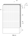
- the portion of detector module 80 may be a direct-conversion type detector module (i.e., the detector elements do not employ a scintillator intermediary), such as a detector based on semiconductor materials as the active material (e.g., silicon) that generates a measurable signal when the semiconductor sensor is itself exposed to X-ray photons.
- a direct-conversion type detector module i.e., the detector elements do not employ a scintillator intermediary
- the active material e.g., silicon
- the detector 28 includes a plurality of such portions of detector module 80 arranged in two dimensions (e.g., the depicted X and Z dimensions) with respect to a cylindrical bore so as to cover the required imaging field of view for each angular position among the multiple angular positions at which X-rays are incident on the detector 28.
- two dimensions e.g., the depicted X and Z dimensions
- the direction traveled by the X-rays 26 i.e., the direction of X-ray propagation
- the direction traveled by the X-rays 26 i.e., the direction of X-ray propagation
- the direction traveled by the X-rays 26 with respect to the source-facing surface of the portion of detector module 80 may be denoted as “vertical” (corresponding to the Y dimension in FIG. 2 ) and/or may be construed as corresponding to a depth dimension so as to provide a geometric frame of reference.
- geometric characterizations such as “vertical” as used herein do not necessarily denote absolute position or orientation information, but are merely intended to simplify discussions by providing a consistent contextual framework.
- the orientation of the detector with respect to the X and Z dimensions may be swapped.
- a portion of detector module 80 includes vertically-segmented (i.e., segmented in the Y dimension) silicon substrates which may be addressed in discrete subunits corresponding to detector elements (i.e., pixels).
- each portion of detector module 80 is fabricated from an assembly of sensor pairs.
- each sensor pair corresponds to readout electronics 84 attached to a pair of focally-aligned silicon wafers 88 extending in the Y dimension.
- an X-ray attenuating material e.g., a tungsten foil or divider, may be provided that acts as an internal collimator 92 within each respective sensor of the pair so as to reduce Compton scatter between detector elements.
- Multiple pairs of wafers 88 and internal collimator 92 may be combined to produce a detector module.
- the readout electronics 84 may comprise application specific integrated circuits (ASICs) that allow readout of signals from the wafers 88, connections or conductive traces to the wafers and to conductor terminals of the respective sensor pair, and so forth.
- ASICs application specific integrated circuits
- each wafer 88 is patterned by electrodes using lithographic or other suitable techniques to define discrete detector elements on each wafer in the X dimension.
- each wafer 88 is patterned into separate detector elements (i.e., pixels) in the X dimension. This is schematically illustrated by the parallel lines 94 depicted on the foremost wafer 88 of FIG. 2 .
- each detector element may be vertically segmented (i.e., segmented in the Y dimension) such that each vertical segment 96 may be separately and/or independently read out, as denoted by the breaks in the lines 94.
- segmentation may be accomplished by electrode patterning on the wafer 88 and need not represent a physical or material break in the substrate.
- Each vertical segment connected to a dedicated ASIC channel, is a fully-functional energy-discriminating photon-counting detector, producing detected counts in one or more energy bins.
- This topology allows measurement of different energy signals at each detector element location, both in the X-Z plane and also along the depth ( Y ) direction. The energy-dependent information may be useful for material decomposition processing and other CT imaging techniques.
- each detector element is effectively an elongated (i.e., high-aspect ratio) detector element that is vertically segmented.
- the segmentation reduces the likelihood of overlapping induced sensor signals arising from incident photons interacting with the sensor material (so called pile-up), thereby providing a detector configuration that has higher count rate performance before behaving non-linearly, i.e., recorded counts not linearly related to incident flux intensity.
- a sensor pair 94 is depicted that encompasses a pair of detector elements 98 (defined by electrode patterning and the boundary of the wafer substrate), here left detector element 98A and right detector element 98B, separated by a tungsten collimator 92 within the sensor pair 94.
- the thickness of wafer 88 is approximately 600 ⁇ m and the thickness of tungsten collimator 92 is approximately 50 ⁇ m.
- an X-ray emission focal spot 120 is also depicted along the Z-dimension axis.
- the focal spot 120 may move along the Z-dimension axis during CT operation as a result of heating of the anode or due to gantry rotation.
- the detector elements 98 e.g., left detector element 98A and right detector element 98B
- a detector element on which the incident X-ray are less attenuated by the respective collimator 92 here right detector element 98B, as illustrated by unimpaired passage of X-ray 20B
- a detector element on which the incident X-rays are more attenuated by the collimator 92 here left detector element 98A, as illustrated by X-ray 20A being limited by the collimator 92, casting shadow 100
- the scan is performed and/or as the focal spot 120 moves along the Z dimension, which detector element is better illuminated by X-rays and which is less illuminated within a given sensor pair 94 may change.
- the incidence of X-rays on a given pair of detector elements 98A, 98B within a sensor pair 94 is complementary, i.e., symmetric about a perfectly aligned position, due to their geometric relationships such that as the X-ray incidence on one decreases due to shadowing by the collimator 92, the incidence on the other increases as it emerges from the shadow.
- the signals or measurements from detector elements 98 comprise signals from one or more individual detector segments, or combinations of the signals from one or more detector segments, wherein combination refers to direct summing or weighted summing of the signals from individual detector segments.
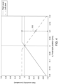
- a transfer function may be derived based on the measured signal acquired by a detector element 98 as a function of focal spot position in the Z dimension.
- This transfer function may be generated based on empirical measurement by measuring the signal generated by paired detector elements within a respective sensor pair 94 at different focal spot positions along the Z dimension. Because, as noted above, these paired detector elements 98 are complementary in terms of their measurements, their respective transfer functions are also complementary.
- the respective gain functions for the paired detector elements are symmetric or complementary.
- a given set of measurements acquired using the respective detector elements 98 of a sensor pair 94 may be evaluated or compared to a graph (such as that depicted) or a corresponding look-up table to determine the focal spot position in the Z dimension for that measurement.
- the respective gain functions for the paired detector elements are symmetric or complementary.
- FIG. 4 depicts a pair of measurements for both a right and left detector element and the corresponding focal spot position in z, as denoted by dashed line 110.
- the methodology will accommodate a finite focal spot size.
- the methodology is discussed with reference to focal spot motion in the Z dimension, the approach is not limited to this dimension and may be used to appropriately accommodate motion where sensor pairs 94 are suitably oriented.
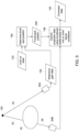
- the ability to obtain an estimate or measure of focal spot position in the Z dimension during a scan may be leveraged in various ways. For example, turning to FIG. 5 , an example is depicted in which sensor pairs on a portion(s) of a detector exposed to unattenuated X-ray emissions 20 (i.e., sensor pairs positioned outside the field-of-view (FOV), depicted as reference sensor pair(s) 94A) are used to estimate focal spot Z position 120.
- FOV field-of-view
- Data acquired by sensors pairs 94 of the detector exposed to X-rays 26 attenuated by the patient 24 or object undergoing imaging may then be adjusted or corrected to account for the estimated focal spot Z position 120 (i.e., focal spot misalignment).
- reference gain data 130 acquired via the reference sensor pair(s) 94A during an examination may be compared to a look-up table 132 or graph, such as discussed with respect to FIG. 4 , such that the reference gain data 130 at a given point in time provides an estimate (i.e., determination step 136) of the position of the focal spot 120 in the Z dimension at that time.
- the determined focal spot position 200 may then be used to correct (step 138) projection data acquired by the active sensor pair(s) 94B at that time, as discussed in greater detail below, to generate corrected projection data 140 which may then be processed (e.g., reconstructed) as normal.
- calibration data may be initially generated for different combinations (i.e., different percentages) of water, bone, and contrast at the different vertical segments of the detector elements 98 for different Z positions of the focal spot. In this manner, when focal spot Z positions are determined, the appropriate calibration corrections may be applied to the projection data acquired by the active sensor pairs.
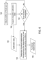
- FIG. 6 An example of a process for generating such calibration data 180 is shown in FIG. 6 .
- the position of the focal spot 120 may be adjusted (step 182) by electromagnetically steering the electron beam impinging on the anode of an X-ray tube in either the axial or transaxial directions.
- calibration data 180 is acquired (step 184) and the focal spot 120 moved to the next position in Z (or X) until all positions of interest have associated calibration data 180 (as determined at decision block 190).
- calibration data 180 may include CT projection data acquired for various defined or determinable operating conditions associated with the calibration scan (e.g., operating voltage of the operating tube, levels of pile-up in the detector, mA setting of the X-ray tube, the combination of materials in the X-ray beam path for spectral calibration, and so forth).
- the number of focal spot positions sampled for a calibration process may be based on the functional dependency of the correction(s) on the specific operating conditions noted above and the number of operating conditions to be characterized.
- functional relationships 196 may be determined (step 194) using the calibration data 180 that characterize the dependency of the calibration measurements on one or more of the input operating conditions. In practice, these functional relationships 196 may be characterized by response surfaces, look-up tables, and so forth.
- these functional relationships 196 may be used at step 138 to correct projection data acquired by the active sensor pairs 94 that acquire data characterizing X-ray transmission through the patient 24. This may be done in a real-time or concurrent manner, or post hoc.
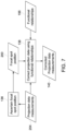
- a process flow for such a correction process for correcting measurement data is shown in FIG. 7 .
- the position 200 of the focal spot 120 is determined (step 136) as described above with respect to FIG. 5 , such as using projection data measurements 204 acquired by a reference sensor pair(s) 94A.
- projection data measurements 204 acquired using active sensor pair(s) 94B may be corrected (step 138) to generate corrected projection data measurements 140.
- the collection of projection data measurements 204 can be used to estimate one or more focal spot positions 200 during scanning procedures.
- projection data measurements 204 collectively can be used to estimate an average focal spot position 200 during scanning, or each projection data measurement, corresponding to a particular orientation of the X-ray source and detector to the object being scanned, can be used to estimate the focal spot position 200 on a view-by-view basis.
- the position of the focal spot 120 in the Z dimension may be used to adjust the focal spot position in real-time so as to maintain its alignment with the detector elements.
- the position of the focal spot 120 in the Z dimension may, as determined from measurements by reference sensor pair(s) 94A, may be provided as an input to the X-ray controller 38, which may adjust the focal spot position to account for drift away from the intended focal spot position.
- the position of the focal spot 120 may be adjusted by electromagnetically steering the electron beam impinging upon the anode in the X-ray tube so as to compensate for any drift in the position of the focal spot 120. In this manner, correction of the projection data for focal spot drift can be avoided as the focal spot is instead maintained in alignment throughout acquisition of projection data for image reconstruction.
- technical effects of the invention include reduction of focal spot motion induced artifacts in CT images.
- the techniques for adjusting focal spot motion during scanning allow for real-time estimation of the misalignment of an X-ray focal spot and X-ray detectors using high aspect ratio detector elements.
- Technical and commercial advantages include, but are not limited to: (1) maintaining image quality in single-energy and multi-energy images at all, i.e., low-dose to high-dose, imaging protocols using electrostatic and electromagnetic steering of the electron beam in real-time; (2) reduced time required for calibration procedures and complexity of same - both for installation calibration and daily calibration procedures executed at the customer site.
Landscapes
- Health & Medical Sciences (AREA)
- Life Sciences & Earth Sciences (AREA)
- Engineering & Computer Science (AREA)
- Medical Informatics (AREA)
- Pathology (AREA)
- Nuclear Medicine, Radiotherapy & Molecular Imaging (AREA)
- Physics & Mathematics (AREA)
- Radiology & Medical Imaging (AREA)
- General Health & Medical Sciences (AREA)
- Public Health (AREA)
- Molecular Biology (AREA)
- Veterinary Medicine (AREA)
- Animal Behavior & Ethology (AREA)
- Surgery (AREA)
- Biomedical Technology (AREA)
- Biophysics (AREA)
- High Energy & Nuclear Physics (AREA)
- Optics & Photonics (AREA)
- Heart & Thoracic Surgery (AREA)
- Pulmonology (AREA)
- Theoretical Computer Science (AREA)
- Biochemistry (AREA)
- Immunology (AREA)
- General Physics & Mathematics (AREA)
- Analytical Chemistry (AREA)
- Chemical & Material Sciences (AREA)
- Apparatus For Radiation Diagnosis (AREA)
- Analysing Materials By The Use Of Radiation (AREA)
- Measurement Of Radiation (AREA)
Claims (13)
- Verfahren zum Erzeugen einer oder mehrerer Funktionsbeziehungen, die zum Korrigieren von durch aktive Röntgensensorpaare (94) erfassten Projektionsdaten geeignet ist/sind, um eine Brennfleckfehlausrichtung zu adressieren, umfassend:Emittieren von Röntgenstrahlen von einem Brennfleck (120) einer Röntgenquelle (12) an einer Vielzahl von Positionen in einer oder mehreren Raumdimensionen;für jede Position Erzeugen gepaarter Antwortdaten, wobei die gepaarten Antwortdaten einen ersten Messwert von einem ersten Detektorelement (98A) eines Sensorpaars und einen zweiten Messwert von einem zweiten Detektorelement (98B) des Sensorpaars umfassen, wobei das erste Detektorelement (98A) und das zweite Detektorelement (98B) des Sensorpaars komplementäre Antwortfunktionen (120) mit Bezug auf eine Bewegung des Brennflecks (120) in der einen oder den mehreren Dimensionen aufweisen;wobei das Sensorpaar eine Schwächungsschicht (92) umfasst, die derart ausgelegt ist, dass sie als ein interner Kollimator innerhalb jedes jeweiligen Sensors des Paars fungiert, wobei die Schwächungsschicht (92) zwischen dem ersten Detektorelement (98A) und dem zweiten Detektorelement (98B) positioniert ist und das erste Detektorelement (98A) von dem zweiten Detektorelement (98B) trennt, wobei eine von der Schwächungsschicht (92) bewirkte Röntgenstrahlschwächung die komplementären Antwortfunktionen des ersten Detektorelements (98A) und des zweiten Detektorelements (98B) mit Bezug auf die Position des Brennflecks (120) in der einen oder den mehreren Raumdimensionen bewirkt; undwobei die komplementären Antwortfunktionen symmetrisch zu einer perfekt ausgerichteten Brennfleckposition sind, sodass, wenn der Röntgenstrahleinfall auf eines von dem ersten Detektorelement (98A) oder dem zweiten Detektorelement (98B) geringer wird, der Einfall auf das andere von dem ersten Detektorelement (98A) oder dem zweiten Detektorelement (98B) höher wird; undZuordnen mindestens der gepaarten Antwortdaten und entsprechender Positionen in der einen oder den mehreren Raumdimensionen, um eine oder mehrere Funktionsbeziehungen (196) zu erzeugen.
- Verfahren nach Anspruch 1, wobei die eine oder die mehreren Raumdimensionen eine Raumdimension in einer Schichtrichtung entlang einer Bohrung eines Computertomographie(CT)-Scanners beinhaltet/beinhalten.
- Verfahren nach Anspruch 1 oder Anspruch 2, wobei das erste Detektorelement (98A) und das zweite Detektorelement (98B) des Sensorpaars ein Konversionsmaterial, das Silicium umfasst und eine hinreichende Dicke in einer Raumdimension aufweist, die der Richtung des Röntgenstrahlengangs entspricht, um eine komplementäre Antwortfunktion zu erkennen, umfassen.
- Verfahren nach einem der vorhergehenden Ansprüche, wobei die eine oder die mehreren Funktionsbeziehungen (196) zusätzlich zu den gepaarten Antwortdaten und den entsprechenden Positionen in der einen oder den mehreren Raumdimensionen ferner eine oder mehrere Betriebsbedingungen einschließt/einschließen.
- Verfahren nach einem der Ansprüche 1 bis 3, wobei die eine oder die mehreren Funktionsbeziehungen (196) eines oder mehrere von Antwortflächen oder Lookup-Tabellen umfasst/umfassen.
- Verfahren nach Anspruch 4, wobei die eine oder die mehreren Betriebsbedingungen eine Betriebsspannung der Röntgenröhre, einen Grad eines Pile-up in dem Detektor, eine mA-Einstellung der Röntgenröhre oder eine Kombination von Materialien auf dem Röntgenstrahlweg zur spektralen Kalibrierung umfasst/umfassen.
- Verfahren zum Adressieren einer Röntgenbrennfleckfehlausrichtung, umfassend:Emittieren von Röntgenstrahlen von einer Röntgenquelle (12), die einen Brennfleck (120) umfasst, wobei die Röntgenstrahlen durch ein Bildgebungsvolumen hindurchtreten, in dem ein Patient oder ein Objekt, der/das gescannt wird, positioniert ist;Erfassen von Antwortdaten von einem oder mehreren Referenzsensorpaaren, das/die dort positioniert ist/sind, wo die auf die Referenzsensorpaare einfallenden Röntgenstrahlen nicht durch den Patienten oder das Objekt hindurchtreten, wobei die Antwortdaten für jedes Referenzsensorpaar einen ersten Messwert von einem ersten Detektorelement (98A) des jeweiligen Sensorpaars und einen zweiten Messwert von einem zweiten Detektorelement (98B) des jeweiligen Sensorpaars umfassen, wobei das erste Detektorelement (98A) und das zweite Detektorelement (98B) jedes Referenzsensorpaars komplementäre Antwortfunktionen mit Bezug auf eine Bewegung des Brennflecks (120) in einer oder mehreren Raumdimensionen aufweisen;obei das eine oder die mehreren Referenzsensorpaare je eine Schwächungsschicht (92) umfasst/umfassen, die derart ausgelegt ist, dass sie als ein interner Kollimator innerhalb jedes jeweiligen Sensors des Paars fungiert, wobei die Schwächungsschicht (92) zwischen dem ersten Detektorelement (98A) und dem zweiten Detektorelement (98B) des jeweiligen Referenzsensorpaars positioniert ist und das erste Detektorelement (98A) von dem zweiten Detektorelement (98B) trennt, wobei eine von der Schwächungsschicht (92) bewirkte Röntgenstrahlschwächung die komplementäre Antwort zwischen dem ersten Detektorelement (98A) und dem zweiten Detektorelement (98B) mit Bezug auf die Position des Brennflecks in einer oder mehreren Raumdimensionen bewirkt; undwobei die komplementären Antwortfunktionen symmetrisch zu einer perfekt ausgerichteten Brennfleckposition sind, sodass, wenn der Röntgenstrahleinfall auf eines von dem ersten Detektorelement (98A) oder dem zweiten Detektorelement (98B) geringer wird, der Einfall auf das andere von dem ersten Detektorelement (98A) oder dem zweiten Detektorelement (98B) höher wird;Bestimmen einer Position in der einen oder den mehreren Raumdimensionen des Brennflecks (120) unter Nutzung der Antwortdaten von dem einen oder den mehreren Referenzsensorpaaren; undDurchführen einer Korrekturaktion basierend auf der Position des Brennflecks (120) in der einen oder den mehreren Raumdimensionen.
- Verfahren nach Anspruch 7, ferner umfassend das Erfassen zusätzlicher Antwortdaten von einer Vielzahl aktiver Sensorpaare, die dort positioniert sind, wo die auf die aktiven Sensorpaare einfallenden Röntgenstrahlen durch den Patienten oder das Objekt hindurchtreten.
- Verfahren nach Anspruch 7 oder Anspruch 8, wobei das Durchführen einer Korrekturaktion Folgendes umfasst:
basierend auf der Position in der einen oder den mehreren Raumdimensionen des Brennflecks (120) Bestimmen einer oder mehrerer Korrekturaktionen zur Durchführung an den zusätzlichen Antwortdaten basierend auf einer oder mehreren zuvor bestimmten Funktionsbeziehungen (196), wobei die Funktionsbeziehungen (196) für unterschiedliche Positionen des Brennflecks (120) in der einen oder den mehreren Raumdimensionen und eine oder mehrere unterschiedliche Betriebsbedingungen abgeleitet werden. - Verfahren nach einem der Ansprüche 7 bis 9, wobei die eine oder die mehreren Funktionsbeziehungen (196) eines oder mehrere von Antwortflächen oder Lookup-Tabellen umfasst/umfassen.
- Verfahren nach Anspruch 9, wobei die unterschiedlichen Betriebsbedingungen eines oder mehrere von einer Betriebsspannung der Röntgenröhre, einem Grad eines Pile-up in dem Detektor, einer mA-Einstellung der Röntgenröhre oder einer Kombination von Materialien auf dem Röntgenstrahlweg zur spektralen Kalibrierung umfassen.
- Verfahren nach einem der Ansprüche 7 bis 11, wobei das Durchführen einer Korrekturaktion das Anpassen der Position des Brennflecks (120) umfasst, um Abweichungen der Position des Brennflecks (120) zu korrigieren.
- Röntgenbildgebungssystem, umfassend:eine Röntgenquelle (12), die derart ausgelegt ist, dass sie während des Betriebs Röntgenstrahlen von einem Brennfleck (120) emittiert;einen Detektor (28), der derart ausgelegt ist, dass er einer Röntgenintensität entsprechende Signale erzeugt, wenn er einer Röntgenstrahlemission von der Röntgenquelle exponiert ist, wobei der Detektor eine Vielzahl von Sensorpaaren umfasst, wobei jedes Sensorpaar ein erstes Detektorelement (98A) und ein zweites Detektorelement (98B) umfasst, die von einer Schwächungsschicht (92) getrennt werden, die derart ausgelegt ist, dass sie als ein interner Kollimator innerhalb jedes jeweiligen Sensors des Paars fungiert, wobei das erste Detektorelement (98A) und ein zweites Detektorelement (98B) komplementäre Antwortfunktionen mit Bezug auf die Position des Brennflecks (120) in einer oder mehreren Raumdimensionen aufweisen;wobei eine von der Schwächungsschicht (92) bewirkte Röntgenstrahlschwächung die komplementäre Antwort zwischen dem ersten Detektorelement (98A) und dem zweiten Detektorelement (98B) mit Bezug auf die Position des Brennflecks in einer oder mehreren Raumdimensionen bewirkt; undwobei die komplementären Antwortfunktionen symmetrisch zu einer perfekt ausgerichteten Brennfleckposition sind, sodass, wenn der Röntgenstrahleinfall auf eines von dem ersten Detektorelement (98A) oder dem zweiten Detektorelement (98B) geringer wird, der Einfall auf das andere von dem ersten Detektorelement (98A) oder dem zweiten Detektorelement (98B) höher wird; undeine oder mehrere Verarbeitungsschaltungen, die für Folgendes ausgelegt ist/sind:Bewirken einer Emission von Röntgenstrahlen von der Röntgenquelle (12), wobei die Röntgenstrahlen während des Betriebs durch ein Bildgebungsvolumen hindurchtreten, in dem ein Patient oder ein Objekt, der/das gescannt wird, positioniert ist;Erfassen von Antwortdaten von einem oder mehreren Referenzsensorpaaren der Vielzahl von Sensorpaaren, wobei die Referenzsensorpaare dort positioniert sind, wo die auf die Referenzsensorpaare einfallenden Röntgenstrahlen nicht durch den Patienten oder das Objekt hindurchtreten;Bestimmen einer Position des Brennflecks (120) in der einen oder den mehreren Raumdimensionen unter Nutzung der Antwortdaten von dem einen oder den mehreren Referenzsensorpaaren; undDurchführen einer Korrekturaktion basierend auf der Position des Brennflecks (120) in der einen oder den mehreren Raumdimensionen.
Applications Claiming Priority (1)
| Application Number | Priority Date | Filing Date | Title |
|---|---|---|---|
| US16/245,938 US10898159B2 (en) | 2019-01-11 | 2019-01-11 | X-ray imaging system use and calibration |
Publications (3)
| Publication Number | Publication Date |
|---|---|
| EP3680650A2 EP3680650A2 (de) | 2020-07-15 |
| EP3680650A3 EP3680650A3 (de) | 2020-12-09 |
| EP3680650B1 true EP3680650B1 (de) | 2024-08-14 |
Family
ID=69157660
Family Applications (1)
| Application Number | Title | Priority Date | Filing Date |
|---|---|---|---|
| EP20151072.4A Active EP3680650B1 (de) | 2019-01-11 | 2020-01-09 | Röntgenbildgebungssystem und verfahren zur korrektur von brennfleckfehlausrichtung |
Country Status (5)
| Country | Link |
|---|---|
| US (1) | US10898159B2 (de) |
| EP (1) | EP3680650B1 (de) |
| JP (1) | JP7123987B2 (de) |
| KR (1) | KR102294774B1 (de) |
| CN (1) | CN111435120B (de) |
Families Citing this family (18)
| Publication number | Priority date | Publication date | Assignee | Title |
|---|---|---|---|---|
| CN107019518B (zh) * | 2016-02-01 | 2020-07-28 | 通用电气公司 | 用于计算机断层扫描中的散射校正的信号处理方法及成像系统 |
| JP7337596B2 (ja) * | 2019-08-20 | 2023-09-04 | キヤノンメディカルシステムズ株式会社 | X線撮影装置、医用情報処理装置、x線検出器及びx線検出器の補正方法 |
| DE102019214212B3 (de) * | 2019-09-18 | 2021-03-11 | Siemens Healthcare Gmbh | Verfahren zur Unterstützung eines Auswerters bei der Auswertung eines Computertomographiedatensatzes, Recheneinrichtung, Computerprogramm und elektronisch lesbarer Datenträger |
| CN110664420B (zh) * | 2019-10-11 | 2023-04-07 | 上海联影医疗科技股份有限公司 | 焦点校正方法、装置、计算机设备和计算机可读存储介质 |
| US11141128B2 (en) * | 2019-12-13 | 2021-10-12 | General Electric Company | Systems and methods for focal spot motion detection and correction |
| US11779296B2 (en) * | 2020-03-20 | 2023-10-10 | Canon Medical Systems Corporation | Photon counting detector based edge reference detector design and calibration method for small pixelated photon counting CT apparatus |
| CN114609684B (zh) * | 2020-12-09 | 2025-03-25 | 同方威视技术股份有限公司 | 物品的检测方法、装置、安检设备、介质和程序产品 |
| CN116831604B (zh) * | 2021-12-06 | 2026-03-27 | 武汉联影生命科学仪器有限公司 | 数据校正方法 |
| CN114399564B (zh) * | 2022-03-25 | 2022-08-12 | 康达洲际医疗器械有限公司 | 一种基于散射识别的锥束计算机断层扫描成像方法与系统 |
| US12176099B2 (en) * | 2022-03-31 | 2024-12-24 | GE Precision Healthcare LLC | Low-cost estimation and/or tracking of intra-scan focal-spot displacement |
| US12125662B2 (en) * | 2022-04-01 | 2024-10-22 | GE Precision Healthcare LLC | Correction of intra-scan focal-spot displacement |
| US12471877B2 (en) * | 2022-06-07 | 2025-11-18 | GE Precision Healthcare LLC | Photon counting computed tomography (PCCT) detector sensor repair for increased sensor yield |
| CN117331110A (zh) * | 2022-06-27 | 2024-01-02 | 上海联影医疗科技股份有限公司 | 一种用于成像系统的探测器 |
| JP2024030533A (ja) * | 2022-08-24 | 2024-03-07 | キヤノンメディカルシステムズ株式会社 | 光子計数型のx線画像診断装置及びパイルアップ補正用の較正データの生成方法 |
| US12239472B2 (en) * | 2022-10-23 | 2025-03-04 | Wisconsin Alumni Research Foundation | Systems and methods for controlling scatter in computed tomography data |
| CN115855983A (zh) * | 2022-11-28 | 2023-03-28 | 武汉联影生命科学仪器有限公司 | 焦点位置校正方法、图像重建方法以及成像系统 |
| JP2024082392A (ja) * | 2022-12-08 | 2024-06-20 | キヤノンメディカルシステムズ株式会社 | X線ct装置、データ処理方法、及びプログラム |
| US12493003B2 (en) * | 2023-07-13 | 2025-12-09 | General Electric Company | Detector with focally aligned pixels |
Citations (1)
| Publication number | Priority date | Publication date | Assignee | Title |
|---|---|---|---|---|
| US20190008474A1 (en) * | 2017-07-06 | 2019-01-10 | Prismatic Sensors Ab | Managing geometric misalignment in x-ray imaging systems |
Family Cites Families (39)
| Publication number | Priority date | Publication date | Assignee | Title |
|---|---|---|---|---|
| EP0490997A4 (en) | 1989-09-06 | 1993-01-27 | The University Of Michigan, Intellectual Property Office | Multi-element-amorphous-silicon-detector-array for real-time imaging and dosimetry of megavoltage photons and diagnostic x-rays |
| US5430785A (en) | 1994-04-11 | 1995-07-04 | General Electric Company | Detector channel gain calibration using focal spot wobble |
| US5550886A (en) * | 1994-11-22 | 1996-08-27 | Analogic Corporation | X-Ray focal spot movement compensation system |
| US5608776A (en) * | 1995-10-10 | 1997-03-04 | General Electric Company | Methods and apparatus for twin beam computed tomography |
| US5657364A (en) * | 1995-12-14 | 1997-08-12 | General Electric Company | Methods and apparatus for detecting beam motion in computed tomography imaging systems |
| US6370218B1 (en) * | 1995-12-21 | 2002-04-09 | General Electric Company | Methods and systems for determining x-ray beam position in multi-slice computed tomography scanners |
| US5706326A (en) | 1995-12-22 | 1998-01-06 | General Electric Company | Systems and methods of determining focal spot x-axis position from projection data |
| JP2000093418A (ja) * | 1998-09-22 | 2000-04-04 | Toshiba Corp | X線検出装置およびx線イメージング装置 |
| US6385279B1 (en) * | 1999-08-27 | 2002-05-07 | General Electric Company | Methods and apparatus for positioning a CT imaging x-ray beam |
| DE102004025119B4 (de) * | 2004-05-21 | 2012-08-02 | Siemens Ag | Röntgenstrahler |
| US7101078B1 (en) * | 2005-02-11 | 2006-09-05 | General Electric Company | Methods and systems for imaging system radiation source alignment |
| US7257187B2 (en) * | 2005-05-06 | 2007-08-14 | General Electric Company | Methods and apparatus for calibrating CT x-ray beam tracking loop |
| US7869561B2 (en) * | 2007-04-10 | 2011-01-11 | Arineta Ltd. | Cone-beam CT |
| US7496180B1 (en) * | 2007-08-29 | 2009-02-24 | General Electric Company | Focal spot temperature reduction using three-point deflection |
| US8183535B2 (en) | 2009-02-11 | 2012-05-22 | Mats Danielsson | Silicon detector assembly for X-ray imaging |
| WO2011010995A1 (en) * | 2009-07-21 | 2011-01-27 | Analogic Corporation | Anti-scatter grid or collimator |
| JP5400546B2 (ja) * | 2009-09-28 | 2014-01-29 | 株式会社日立メディコ | X線ct装置 |
| US8262288B2 (en) * | 2010-01-21 | 2012-09-11 | Analogic Corporation | Focal spot position determiner |
| CN102335002B (zh) * | 2010-07-16 | 2015-01-14 | Ge医疗系统环球技术有限公司 | Ct机x光发生器及探测器位置校准工具,校准工具的校准方法和ct系统校准方法 |
| JP2013536412A (ja) * | 2010-07-23 | 2013-09-19 | アンラッド コーポレーション | 電圧を用いて放射線検出器を補正する方法 |
| US20120223227A1 (en) * | 2011-03-04 | 2012-09-06 | Chien-Huei Chen | Apparatus and methods for real-time three-dimensional sem imaging and viewing of semiconductor wafers |
| US20120236987A1 (en) * | 2011-03-18 | 2012-09-20 | David Ruimi | Multiple energy ct scanner |
| US8699659B2 (en) * | 2011-06-23 | 2014-04-15 | General Electric Company | Systems and methods for focal spot motion correction |
| JP5863292B2 (ja) * | 2011-06-30 | 2016-02-16 | ジーイー・メディカル・システムズ・グローバル・テクノロジー・カンパニー・エルエルシー | X線ct装置 |
| CN103648391B (zh) * | 2011-07-12 | 2016-08-17 | 皇家飞利浦有限公司 | 成像系统探测器校准 |
| CA2848139A1 (en) * | 2011-09-08 | 2013-03-14 | Apn Health, Llc | R-wave detection method |
| US8926177B2 (en) * | 2012-05-21 | 2015-01-06 | General Electric Company | Source side monitoring device for an imaging system |
| DE102012214387B4 (de) * | 2012-08-13 | 2018-08-02 | Siemens Healthcare Gmbh | Röntgendetektor und Verfahren zum Betrieb eines Röntgendetektors |
| US9271683B2 (en) * | 2012-11-30 | 2016-03-01 | General Electric Company | Radiation focal position detecting method, radiation detecting apparatus and radiation tomographic imaging apparatus |
| US9237872B2 (en) * | 2013-01-18 | 2016-01-19 | General Electric Company | X-ray source with moving anode or cathode |
| US9750471B2 (en) * | 2013-05-10 | 2017-09-05 | Koninklijke Philips N.V. | Photon-counting detector calibration |
| US9377416B2 (en) * | 2014-05-17 | 2016-06-28 | Kla-Tencor Corp. | Wafer edge detection and inspection |
| US20160199019A1 (en) * | 2015-01-13 | 2016-07-14 | Arineta Ltd. | Method and apparatus for focal spot position tracking |
| JP6529596B2 (ja) * | 2015-09-17 | 2019-06-12 | 株式会社日立製作所 | X線ct装置及びx線ct装置における焦点位置制御方法 |
| US10383202B2 (en) * | 2016-04-28 | 2019-08-13 | Varex Imaging Corporation | Electronic focal spot alignment of an x-ray tube |
| US10383203B2 (en) * | 2016-04-28 | 2019-08-13 | Varex Imaging Corporation | Electronic calibration of focal spot position in an X-ray tube |
| US10433811B2 (en) * | 2016-12-23 | 2019-10-08 | General Electric Company | Self-calibrating CT detectors, systems and methods for self-calibration |
| US10779778B2 (en) * | 2017-05-08 | 2020-09-22 | General Electric Company | Reference detector elements in conjunction with an anti-scatter collimator |
| US10631815B2 (en) * | 2017-05-10 | 2020-04-28 | General Electric Company | Scatter correction technique for use with a radiation detector |
-
2019
- 2019-01-11 US US16/245,938 patent/US10898159B2/en active Active
- 2019-12-30 KR KR1020190177730A patent/KR102294774B1/ko active Active
- 2019-12-31 CN CN201911419668.9A patent/CN111435120B/zh active Active
-
2020
- 2020-01-07 JP JP2020000639A patent/JP7123987B2/ja active Active
- 2020-01-09 EP EP20151072.4A patent/EP3680650B1/de active Active
Patent Citations (1)
| Publication number | Priority date | Publication date | Assignee | Title |
|---|---|---|---|---|
| US20190008474A1 (en) * | 2017-07-06 | 2019-01-10 | Prismatic Sensors Ab | Managing geometric misalignment in x-ray imaging systems |
Also Published As
| Publication number | Publication date |
|---|---|
| US20200222024A1 (en) | 2020-07-16 |
| US10898159B2 (en) | 2021-01-26 |
| JP7123987B2 (ja) | 2022-08-23 |
| KR20200087686A (ko) | 2020-07-21 |
| CN111435120A (zh) | 2020-07-21 |
| CN111435120B (zh) | 2024-04-05 |
| JP2020127709A (ja) | 2020-08-27 |
| EP3680650A2 (de) | 2020-07-15 |
| KR102294774B1 (ko) | 2021-08-27 |
| EP3680650A3 (de) | 2020-12-09 |
Similar Documents
| Publication | Publication Date | Title |
|---|---|---|
| EP3680650B1 (de) | Röntgenbildgebungssystem und verfahren zur korrektur von brennfleckfehlausrichtung | |
| US10827992B2 (en) | Energy-discriminating photon-counting detector and the use thereof | |
| EP3596511B1 (de) | Entwurf eines strahlendetektorelements | |
| US9269168B2 (en) | Volume image reconstruction using data from multiple energy spectra | |
| EP3635440B1 (de) | Streuungskorrekturverfahren zur verwendung in einem strahlungsdetektor | |
| US10779778B2 (en) | Reference detector elements in conjunction with an anti-scatter collimator | |
| US10470723B2 (en) | X-ray device with reduced pile-up | |
| JP7820134B2 (ja) | 光子計数型x線ct装置及び方法 | |
| EP3835830B1 (de) | Systeme und methoden zur abschätzung einer brennpunktbewegung und zur berechnung einer entspechenden korrektur | |
| EP3517038B1 (de) | System und verfahren zur verbesserung der räumlichen auflösung in der computertomographie | |
| JP2025123362A (ja) | X線ct装置、データ処理方法及びプログラム | |
| EP4111978B1 (de) | Systeme und verfahren zur bewegungsdetektion im brennpunkt sowohl in x- als auch in y-richtung und zur korrektur |
Legal Events
| Date | Code | Title | Description |
|---|---|---|---|
| PUAI | Public reference made under article 153(3) epc to a published international application that has entered the european phase |
Free format text: ORIGINAL CODE: 0009012 |
|
| STAA | Information on the status of an ep patent application or granted ep patent |
Free format text: STATUS: REQUEST FOR EXAMINATION WAS MADE |
|
| 17P | Request for examination filed |
Effective date: 20200109 |
|
| AK | Designated contracting states |
Kind code of ref document: A2 Designated state(s): AL AT BE BG CH CY CZ DE DK EE ES FI FR GB GR HR HU IE IS IT LI LT LU LV MC MK MT NL NO PL PT RO RS SE SI SK SM TR |
|
| AX | Request for extension of the european patent |
Extension state: BA ME |
|
| PUAL | Search report despatched |
Free format text: ORIGINAL CODE: 0009013 |
|
| AK | Designated contracting states |
Kind code of ref document: A3 Designated state(s): AL AT BE BG CH CY CZ DE DK EE ES FI FR GB GR HR HU IE IS IT LI LT LU LV MC MK MT NL NO PL PT RO RS SE SI SK SM TR |
|
| AX | Request for extension of the european patent |
Extension state: BA ME |
|
| RIC1 | Information provided on ipc code assigned before grant |
Ipc: G01N 23/046 20180101AFI20201102BHEP |
|
| RIN1 | Information on inventor provided before grant (corrected) |
Inventor name: EDIC, PETER MICHAEL Inventor name: JACOB, BIJU |
|
| STAA | Information on the status of an ep patent application or granted ep patent |
Free format text: STATUS: EXAMINATION IS IN PROGRESS |
|
| 17Q | First examination report despatched |
Effective date: 20220407 |
|
| P01 | Opt-out of the competence of the unified patent court (upc) registered |
Effective date: 20230528 |
|
| GRAP | Despatch of communication of intention to grant a patent |
Free format text: ORIGINAL CODE: EPIDOSNIGR1 |
|
| STAA | Information on the status of an ep patent application or granted ep patent |
Free format text: STATUS: GRANT OF PATENT IS INTENDED |
|
| INTG | Intention to grant announced |
Effective date: 20231011 |
|
| GRAJ | Information related to disapproval of communication of intention to grant by the applicant or resumption of examination proceedings by the epo deleted |
Free format text: ORIGINAL CODE: EPIDOSDIGR1 |
|
| STAA | Information on the status of an ep patent application or granted ep patent |
Free format text: STATUS: EXAMINATION IS IN PROGRESS |
|
| GRAP | Despatch of communication of intention to grant a patent |
Free format text: ORIGINAL CODE: EPIDOSNIGR1 |
|
| STAA | Information on the status of an ep patent application or granted ep patent |
Free format text: STATUS: GRANT OF PATENT IS INTENDED |
|
| INTC | Intention to grant announced (deleted) | ||
| INTG | Intention to grant announced |
Effective date: 20240314 |
|
| GRAS | Grant fee paid |
Free format text: ORIGINAL CODE: EPIDOSNIGR3 |
|
| GRAA | (expected) grant |
Free format text: ORIGINAL CODE: 0009210 |
|
| STAA | Information on the status of an ep patent application or granted ep patent |
Free format text: STATUS: THE PATENT HAS BEEN GRANTED |
|
| AK | Designated contracting states |
Kind code of ref document: B1 Designated state(s): AL AT BE BG CH CY CZ DE DK EE ES FI FR GB GR HR HU IE IS IT LI LT LU LV MC MK MT NL NO PL PT RO RS SE SI SK SM TR |
|
| REG | Reference to a national code |
Ref country code: GB Ref legal event code: FG4D |
|
| REG | Reference to a national code |
Ref country code: CH Ref legal event code: EP |
|
| REG | Reference to a national code |
Ref country code: NL Ref legal event code: FP |
|
| REG | Reference to a national code |
Ref country code: DE Ref legal event code: R096 Ref document number: 602020035593 Country of ref document: DE |
|
| REG | Reference to a national code |
Ref country code: IE Ref legal event code: FG4D |
|
| REG | Reference to a national code |
Ref country code: LT Ref legal event code: MG9D |
|
| PG25 | Lapsed in a contracting state [announced via postgrant information from national office to epo] |
Ref country code: NO Free format text: LAPSE BECAUSE OF FAILURE TO SUBMIT A TRANSLATION OF THE DESCRIPTION OR TO PAY THE FEE WITHIN THE PRESCRIBED TIME-LIMIT Effective date: 20241114 |
|
| REG | Reference to a national code |
Ref country code: AT Ref legal event code: MK05 Ref document number: 1713714 Country of ref document: AT Kind code of ref document: T Effective date: 20240814 |
|
| PG25 | Lapsed in a contracting state [announced via postgrant information from national office to epo] |
Ref country code: FI Free format text: LAPSE BECAUSE OF FAILURE TO SUBMIT A TRANSLATION OF THE DESCRIPTION OR TO PAY THE FEE WITHIN THE PRESCRIBED TIME-LIMIT Effective date: 20240814 Ref country code: PL Free format text: LAPSE BECAUSE OF FAILURE TO SUBMIT A TRANSLATION OF THE DESCRIPTION OR TO PAY THE FEE WITHIN THE PRESCRIBED TIME-LIMIT Effective date: 20240814 Ref country code: GR Free format text: LAPSE BECAUSE OF FAILURE TO SUBMIT A TRANSLATION OF THE DESCRIPTION OR TO PAY THE FEE WITHIN THE PRESCRIBED TIME-LIMIT Effective date: 20241115 Ref country code: PT Free format text: LAPSE BECAUSE OF FAILURE TO SUBMIT A TRANSLATION OF THE DESCRIPTION OR TO PAY THE FEE WITHIN THE PRESCRIBED TIME-LIMIT Effective date: 20241216 |
|
| PG25 | Lapsed in a contracting state [announced via postgrant information from national office to epo] |
Ref country code: BG Free format text: LAPSE BECAUSE OF FAILURE TO SUBMIT A TRANSLATION OF THE DESCRIPTION OR TO PAY THE FEE WITHIN THE PRESCRIBED TIME-LIMIT Effective date: 20240814 |
|
| PG25 | Lapsed in a contracting state [announced via postgrant information from national office to epo] |
Ref country code: LV Free format text: LAPSE BECAUSE OF FAILURE TO SUBMIT A TRANSLATION OF THE DESCRIPTION OR TO PAY THE FEE WITHIN THE PRESCRIBED TIME-LIMIT Effective date: 20240814 |
|
| PG25 | Lapsed in a contracting state [announced via postgrant information from national office to epo] |
Ref country code: AT Free format text: LAPSE BECAUSE OF FAILURE TO SUBMIT A TRANSLATION OF THE DESCRIPTION OR TO PAY THE FEE WITHIN THE PRESCRIBED TIME-LIMIT Effective date: 20240814 Ref country code: IS Free format text: LAPSE BECAUSE OF FAILURE TO SUBMIT A TRANSLATION OF THE DESCRIPTION OR TO PAY THE FEE WITHIN THE PRESCRIBED TIME-LIMIT Effective date: 20241214 |
|
| PG25 | Lapsed in a contracting state [announced via postgrant information from national office to epo] |
Ref country code: HR Free format text: LAPSE BECAUSE OF FAILURE TO SUBMIT A TRANSLATION OF THE DESCRIPTION OR TO PAY THE FEE WITHIN THE PRESCRIBED TIME-LIMIT Effective date: 20240814 |
|
| PG25 | Lapsed in a contracting state [announced via postgrant information from national office to epo] |
Ref country code: ES Free format text: LAPSE BECAUSE OF FAILURE TO SUBMIT A TRANSLATION OF THE DESCRIPTION OR TO PAY THE FEE WITHIN THE PRESCRIBED TIME-LIMIT Effective date: 20240814 Ref country code: RS Free format text: LAPSE BECAUSE OF FAILURE TO SUBMIT A TRANSLATION OF THE DESCRIPTION OR TO PAY THE FEE WITHIN THE PRESCRIBED TIME-LIMIT Effective date: 20241114 |
|
| PG25 | Lapsed in a contracting state [announced via postgrant information from national office to epo] |
Ref country code: RS Free format text: LAPSE BECAUSE OF FAILURE TO SUBMIT A TRANSLATION OF THE DESCRIPTION OR TO PAY THE FEE WITHIN THE PRESCRIBED TIME-LIMIT Effective date: 20241114 Ref country code: PT Free format text: LAPSE BECAUSE OF FAILURE TO SUBMIT A TRANSLATION OF THE DESCRIPTION OR TO PAY THE FEE WITHIN THE PRESCRIBED TIME-LIMIT Effective date: 20241216 Ref country code: PL Free format text: LAPSE BECAUSE OF FAILURE TO SUBMIT A TRANSLATION OF THE DESCRIPTION OR TO PAY THE FEE WITHIN THE PRESCRIBED TIME-LIMIT Effective date: 20240814 Ref country code: NO Free format text: LAPSE BECAUSE OF FAILURE TO SUBMIT A TRANSLATION OF THE DESCRIPTION OR TO PAY THE FEE WITHIN THE PRESCRIBED TIME-LIMIT Effective date: 20241114 Ref country code: LV Free format text: LAPSE BECAUSE OF FAILURE TO SUBMIT A TRANSLATION OF THE DESCRIPTION OR TO PAY THE FEE WITHIN THE PRESCRIBED TIME-LIMIT Effective date: 20240814 Ref country code: IS Free format text: LAPSE BECAUSE OF FAILURE TO SUBMIT A TRANSLATION OF THE DESCRIPTION OR TO PAY THE FEE WITHIN THE PRESCRIBED TIME-LIMIT Effective date: 20241214 Ref country code: HR Free format text: LAPSE BECAUSE OF FAILURE TO SUBMIT A TRANSLATION OF THE DESCRIPTION OR TO PAY THE FEE WITHIN THE PRESCRIBED TIME-LIMIT Effective date: 20240814 Ref country code: GR Free format text: LAPSE BECAUSE OF FAILURE TO SUBMIT A TRANSLATION OF THE DESCRIPTION OR TO PAY THE FEE WITHIN THE PRESCRIBED TIME-LIMIT Effective date: 20241115 Ref country code: FI Free format text: LAPSE BECAUSE OF FAILURE TO SUBMIT A TRANSLATION OF THE DESCRIPTION OR TO PAY THE FEE WITHIN THE PRESCRIBED TIME-LIMIT Effective date: 20240814 Ref country code: ES Free format text: LAPSE BECAUSE OF FAILURE TO SUBMIT A TRANSLATION OF THE DESCRIPTION OR TO PAY THE FEE WITHIN THE PRESCRIBED TIME-LIMIT Effective date: 20240814 Ref country code: BG Free format text: LAPSE BECAUSE OF FAILURE TO SUBMIT A TRANSLATION OF THE DESCRIPTION OR TO PAY THE FEE WITHIN THE PRESCRIBED TIME-LIMIT Effective date: 20240814 Ref country code: AT Free format text: LAPSE BECAUSE OF FAILURE TO SUBMIT A TRANSLATION OF THE DESCRIPTION OR TO PAY THE FEE WITHIN THE PRESCRIBED TIME-LIMIT Effective date: 20240814 |
|
| PGFP | Annual fee paid to national office [announced via postgrant information from national office to epo] |
Ref country code: DE Payment date: 20241218 Year of fee payment: 6 |
|
| PG25 | Lapsed in a contracting state [announced via postgrant information from national office to epo] |
Ref country code: DK Free format text: LAPSE BECAUSE OF FAILURE TO SUBMIT A TRANSLATION OF THE DESCRIPTION OR TO PAY THE FEE WITHIN THE PRESCRIBED TIME-LIMIT Effective date: 20240814 Ref country code: SM Free format text: LAPSE BECAUSE OF FAILURE TO SUBMIT A TRANSLATION OF THE DESCRIPTION OR TO PAY THE FEE WITHIN THE PRESCRIBED TIME-LIMIT Effective date: 20240814 Ref country code: RO Free format text: LAPSE BECAUSE OF FAILURE TO SUBMIT A TRANSLATION OF THE DESCRIPTION OR TO PAY THE FEE WITHIN THE PRESCRIBED TIME-LIMIT Effective date: 20240814 |
|
| PG25 | Lapsed in a contracting state [announced via postgrant information from national office to epo] |
Ref country code: EE Free format text: LAPSE BECAUSE OF FAILURE TO SUBMIT A TRANSLATION OF THE DESCRIPTION OR TO PAY THE FEE WITHIN THE PRESCRIBED TIME-LIMIT Effective date: 20240814 |
|
| PG25 | Lapsed in a contracting state [announced via postgrant information from national office to epo] |
Ref country code: CZ Free format text: LAPSE BECAUSE OF FAILURE TO SUBMIT A TRANSLATION OF THE DESCRIPTION OR TO PAY THE FEE WITHIN THE PRESCRIBED TIME-LIMIT Effective date: 20240814 |
|
| PG25 | Lapsed in a contracting state [announced via postgrant information from national office to epo] |
Ref country code: SK Free format text: LAPSE BECAUSE OF FAILURE TO SUBMIT A TRANSLATION OF THE DESCRIPTION OR TO PAY THE FEE WITHIN THE PRESCRIBED TIME-LIMIT Effective date: 20240814 Ref country code: IT Free format text: LAPSE BECAUSE OF FAILURE TO SUBMIT A TRANSLATION OF THE DESCRIPTION OR TO PAY THE FEE WITHIN THE PRESCRIBED TIME-LIMIT Effective date: 20240814 |
|
| REG | Reference to a national code |
Ref country code: DE Ref legal event code: R097 Ref document number: 602020035593 Country of ref document: DE |
|
| REG | Reference to a national code |
Ref country code: NL Ref legal event code: PD Owner name: GE PRECISION HEALTHCARE LLC; US Free format text: DETAILS ASSIGNMENT: CHANGE OF OWNER(S), ASSIGNMENT; FORMER OWNER NAME: GENERAL ELECTRIC COMPANY Effective date: 20250604 |
|
| PLBE | No opposition filed within time limit |
Free format text: ORIGINAL CODE: 0009261 |
|
| STAA | Information on the status of an ep patent application or granted ep patent |
Free format text: STATUS: NO OPPOSITION FILED WITHIN TIME LIMIT |
|
| REG | Reference to a national code |
Ref country code: DE Ref legal event code: R081 Ref document number: 602020035593 Country of ref document: DE Owner name: GE PRECISION HEALTHCARE LLC, WAUKESHA, US Free format text: FORMER OWNER: GENERAL ELECTRIC COMPANY, SCHENECTADY, NY, US |
|
| 26N | No opposition filed |
Effective date: 20250515 |
|
| REG | Reference to a national code |
Ref country code: CH Ref legal event code: PL |
|
| REG | Reference to a national code |
Ref country code: GB Ref legal event code: 732E Free format text: REGISTERED BETWEEN 20250807 AND 20250813 |
|
| PG25 | Lapsed in a contracting state [announced via postgrant information from national office to epo] |
Ref country code: SE Free format text: LAPSE BECAUSE OF FAILURE TO SUBMIT A TRANSLATION OF THE DESCRIPTION OR TO PAY THE FEE WITHIN THE PRESCRIBED TIME-LIMIT Effective date: 20240814 |
|
| PG25 | Lapsed in a contracting state [announced via postgrant information from national office to epo] |
Ref country code: MC Free format text: LAPSE BECAUSE OF FAILURE TO SUBMIT A TRANSLATION OF THE DESCRIPTION OR TO PAY THE FEE WITHIN THE PRESCRIBED TIME-LIMIT Effective date: 20240814 Ref country code: LU Free format text: LAPSE BECAUSE OF NON-PAYMENT OF DUE FEES Effective date: 20250109 |
|
| PG25 | Lapsed in a contracting state [announced via postgrant information from national office to epo] |
Ref country code: BE Free format text: LAPSE BECAUSE OF NON-PAYMENT OF DUE FEES Effective date: 20250131 |
|
| PG25 | Lapsed in a contracting state [announced via postgrant information from national office to epo] |
Ref country code: CH Free format text: LAPSE BECAUSE OF NON-PAYMENT OF DUE FEES Effective date: 20250131 |
|
| REG | Reference to a national code |
Ref country code: BE Ref legal event code: MM Effective date: 20250131 |
|
| PGFP | Annual fee paid to national office [announced via postgrant information from national office to epo] |
Ref country code: GB Payment date: 20251219 Year of fee payment: 7 |
|
| PGFP | Annual fee paid to national office [announced via postgrant information from national office to epo] |
Ref country code: FR Payment date: 20251217 Year of fee payment: 7 Ref country code: NL Payment date: 20251217 Year of fee payment: 7 |
|
| PG25 | Lapsed in a contracting state [announced via postgrant information from national office to epo] |
Ref country code: IE Free format text: LAPSE BECAUSE OF NON-PAYMENT OF DUE FEES Effective date: 20250109 |