EP3680552B1 - Structure de dispositif de chauffage - Google Patents
Structure de dispositif de chauffage Download PDFInfo
- Publication number
- EP3680552B1 EP3680552B1 EP19211081.5A EP19211081A EP3680552B1 EP 3680552 B1 EP3680552 B1 EP 3680552B1 EP 19211081 A EP19211081 A EP 19211081A EP 3680552 B1 EP3680552 B1 EP 3680552B1
- Authority
- EP
- European Patent Office
- Prior art keywords
- operator
- ignition
- shut
- switch
- fuel gas
- Prior art date
- Legal status (The legal status is an assumption and is not a legal conclusion. Google has not performed a legal analysis and makes no representation as to the accuracy of the status listed.)
- Active
Links
Images


Classifications
-
- F—MECHANICAL ENGINEERING; LIGHTING; HEATING; WEAPONS; BLASTING
- F24—HEATING; RANGES; VENTILATING
- F24H—FLUID HEATERS, e.g. WATER OR AIR HEATERS, HAVING HEAT-GENERATING MEANS, e.g. HEAT PUMPS, IN GENERAL
- F24H9/00—Details
- F24H9/20—Arrangement or mounting of control or safety devices
- F24H9/2064—Arrangement or mounting of control or safety devices for air heaters
- F24H9/2085—Arrangement or mounting of control or safety devices for air heaters using fluid fuel
-
- F—MECHANICAL ENGINEERING; LIGHTING; HEATING; WEAPONS; BLASTING
- F23—COMBUSTION APPARATUS; COMBUSTION PROCESSES
- F23N—REGULATING OR CONTROLLING COMBUSTION
- F23N1/00—Regulating fuel supply
- F23N1/007—Regulating fuel supply using mechanical means
-
- F—MECHANICAL ENGINEERING; LIGHTING; HEATING; WEAPONS; BLASTING
- F23—COMBUSTION APPARATUS; COMBUSTION PROCESSES
- F23D—BURNERS
- F23D14/00—Burners for combustion of a gas, e.g. of a gas stored under pressure as a liquid
- F23D14/26—Burners for combustion of a gas, e.g. of a gas stored under pressure as a liquid with provision for a retention flame
-
- F—MECHANICAL ENGINEERING; LIGHTING; HEATING; WEAPONS; BLASTING
- F23—COMBUSTION APPARATUS; COMBUSTION PROCESSES
- F23D—BURNERS
- F23D14/00—Burners for combustion of a gas, e.g. of a gas stored under pressure as a liquid
- F23D14/46—Details
- F23D14/72—Safety devices, e.g. operative in case of failure of gas supply
- F23D14/76—Protecting flame and burner parts
-
- F—MECHANICAL ENGINEERING; LIGHTING; HEATING; WEAPONS; BLASTING
- F23—COMBUSTION APPARATUS; COMBUSTION PROCESSES
- F23K—FEEDING FUEL TO COMBUSTION APPARATUS
- F23K5/00—Feeding or distributing other fuel to combustion apparatus
- F23K5/002—Gaseous fuel
- F23K5/007—Details
-
- F—MECHANICAL ENGINEERING; LIGHTING; HEATING; WEAPONS; BLASTING
- F23—COMBUSTION APPARATUS; COMBUSTION PROCESSES
- F23N—REGULATING OR CONTROLLING COMBUSTION
- F23N5/00—Systems for controlling combustion
- F23N5/24—Preventing development of abnormal or undesired conditions, i.e. safety arrangements
- F23N5/247—Preventing development of abnormal or undesired conditions, i.e. safety arrangements using mechanical means
-
- F—MECHANICAL ENGINEERING; LIGHTING; HEATING; WEAPONS; BLASTING
- F23—COMBUSTION APPARATUS; COMBUSTION PROCESSES
- F23Q—IGNITION; EXTINGUISHING-DEVICES
- F23Q3/00—Igniters using electrically-produced sparks
- F23Q3/008—Structurally associated with fluid-fuel burners
-
- F—MECHANICAL ENGINEERING; LIGHTING; HEATING; WEAPONS; BLASTING
- F23—COMBUSTION APPARATUS; COMBUSTION PROCESSES
- F23Q—IGNITION; EXTINGUISHING-DEVICES
- F23Q9/00—Pilot flame igniters
-
- F—MECHANICAL ENGINEERING; LIGHTING; HEATING; WEAPONS; BLASTING
- F24—HEATING; RANGES; VENTILATING
- F24C—DOMESTIC STOVES OR RANGES ; DETAILS OF DOMESTIC STOVES OR RANGES, OF GENERAL APPLICATION
- F24C3/00—Stoves or ranges for gaseous fuels
- F24C3/04—Stoves or ranges for gaseous fuels with heat produced wholly or partly by a radiant body, e.g. by a perforated plate
- F24C3/042—Stoves
-
- F—MECHANICAL ENGINEERING; LIGHTING; HEATING; WEAPONS; BLASTING
- F24—HEATING; RANGES; VENTILATING
- F24H—FLUID HEATERS, e.g. WATER OR AIR HEATERS, HAVING HEAT-GENERATING MEANS, e.g. HEAT PUMPS, IN GENERAL
- F24H3/00—Air heaters
- F24H3/02—Air heaters with forced circulation
- F24H3/04—Air heaters with forced circulation the air being in direct contact with the heating medium, e.g. electric heating element
- F24H3/0405—Air heaters with forced circulation the air being in direct contact with the heating medium, e.g. electric heating element using electric energy supply, e.g. the heating medium being a resistive element; Heating by direct contact, i.e. with resistive elements, electrodes and fins being bonded together without additional element in-between
- F24H3/0411—Air heaters with forced circulation the air being in direct contact with the heating medium, e.g. electric heating element using electric energy supply, e.g. the heating medium being a resistive element; Heating by direct contact, i.e. with resistive elements, electrodes and fins being bonded together without additional element in-between for domestic or space-heating systems
-
- F—MECHANICAL ENGINEERING; LIGHTING; HEATING; WEAPONS; BLASTING
- F23—COMBUSTION APPARATUS; COMBUSTION PROCESSES
- F23K—FEEDING FUEL TO COMBUSTION APPARATUS
- F23K2900/00—Special features of, or arrangements for fuel supplies
- F23K2900/05001—Control or safety devices in gaseous or liquid fuel supply lines
-
- F—MECHANICAL ENGINEERING; LIGHTING; HEATING; WEAPONS; BLASTING
- F23—COMBUSTION APPARATUS; COMBUSTION PROCESSES
- F23K—FEEDING FUEL TO COMBUSTION APPARATUS
- F23K2900/00—Special features of, or arrangements for fuel supplies
- F23K2900/05002—Valves for gaseous fuel supply lines
-
- F—MECHANICAL ENGINEERING; LIGHTING; HEATING; WEAPONS; BLASTING
- F23—COMBUSTION APPARATUS; COMBUSTION PROCESSES
- F23N—REGULATING OR CONTROLLING COMBUSTION
- F23N2227/00—Ignition or checking
- F23N2227/22—Pilot burners
-
- F—MECHANICAL ENGINEERING; LIGHTING; HEATING; WEAPONS; BLASTING
- F23—COMBUSTION APPARATUS; COMBUSTION PROCESSES
- F23N—REGULATING OR CONTROLLING COMBUSTION
- F23N2227/00—Ignition or checking
- F23N2227/28—Ignition circuits
- F23N2227/30—Ignition circuits for pilot burners
-
- F—MECHANICAL ENGINEERING; LIGHTING; HEATING; WEAPONS; BLASTING
- F23—COMBUSTION APPARATUS; COMBUSTION PROCESSES
- F23N—REGULATING OR CONTROLLING COMBUSTION
- F23N2227/00—Ignition or checking
- F23N2227/36—Spark ignition, e.g. by means of a high voltage
-
- F—MECHANICAL ENGINEERING; LIGHTING; HEATING; WEAPONS; BLASTING
- F23—COMBUSTION APPARATUS; COMBUSTION PROCESSES
- F23N—REGULATING OR CONTROLLING COMBUSTION
- F23N2235/00—Valves, nozzles or pumps
- F23N2235/12—Fuel valves
-
- F—MECHANICAL ENGINEERING; LIGHTING; HEATING; WEAPONS; BLASTING
- F23—COMBUSTION APPARATUS; COMBUSTION PROCESSES
- F23N—REGULATING OR CONTROLLING COMBUSTION
- F23N2235/00—Valves, nozzles or pumps
- F23N2235/12—Fuel valves
- F23N2235/24—Valve details
-
- F—MECHANICAL ENGINEERING; LIGHTING; HEATING; WEAPONS; BLASTING
- F23—COMBUSTION APPARATUS; COMBUSTION PROCESSES
- F23N—REGULATING OR CONTROLLING COMBUSTION
- F23N2241/00—Applications
- F23N2241/02—Space-heating
-
- F—MECHANICAL ENGINEERING; LIGHTING; HEATING; WEAPONS; BLASTING
- F23—COMBUSTION APPARATUS; COMBUSTION PROCESSES
- F23N—REGULATING OR CONTROLLING COMBUSTION
- F23N2900/00—Special features of, or arrangements for controlling combustion
- F23N2900/05005—Mounting arrangements for sensing, detecting or measuring devices
Definitions
- the present invention relates generally to a heater structure, and more particularly to a heater structure that allows a user to easily operate a switch for supplying fuel gas, igniting a burner, and cutting off the supply of fuel gas so as to reduce influence of a pilot fire by an outside airflow.
- Heaters such as outdoor heating devices that are commonly available in the market are generally of a structure that uses a burner (such as an infrared ceramic burner) to heat air surrounding the heater in order to achieve the purpose of heating and warming outdoors.
- the heater may keep generating high temperature through continuous supply of fuel gas for applications of heating and warm-keeping.
- a known outdoor heater is located outdoors and the flame of the burner is often blown out by winds or gusts. A user needs to frequently re-ignite the burner by operating an ignition switch. This is inconvenient and troublesome. Therefore, for an outdoor heater, operability of the ignition switch in respect of the functionality and structure thereof and users' convenience of operation are vital.
- the known outdoor heater does not provide any protection measure for a pilot fire generated by a pilot fire assembly and thus, the pilot fire may get randomly moved or even blown out. This results in malfunctioning of a thermocouple, and eventually lead to failure of the outdoor heater. Thus, it would be vital to provide the pilot fire assembly with a protection structure
- WO 95/28603 A1 discloses a heater structure, comprising a heater body comprising a burner, which is connected to a gas supply tube, and valve switch which is adapted to connect to a fuel gas supply source, the valve switch being provided on its side with a fuel gas valve rod, which functions to control the valve switch to supply or not supply fuel gas to the burner; a pilot, and a switch unit which is mounted to the valve switch, the mounting frame comprising an ignition switch connected to an ignition circuit of an ignition electrode, a shut-down switch connected to a circuit of the thermocouple, an ignition operator, and a shut-down operator.
- the ignition operator and the shut-down operator are combined in one operator, the ignition switch and the fuel gas valve rod are arranged below the ignition operator to be contactable and pressable down by the ignition operator; and the shut-down switch is arranged above the shut-down operator to be contactable and pressable by the shut-down operator.
- US 2016/123589 A1 discloses an example of a pilot assembly.
- An objective of the present invention is to provide a heater structure that allows a user to easily operate a switch for supply fuel gas, igniting a burner, and cutting of the supply of fuel gas and also to reduce influence imposed on a pilot fire by external airflows.
- the present invention provides a structure that comprises a heater body, a pilot fire assembly, and a switch unit, wherein the heater body comprises a burner, which is connected to a gas supply tube, and a valve switch, which is adapted to connect to a fuel gas supply source, the valve switch being provided on a top side thereof with a fuel gas valve rod, which functions to control the valve switch to supply or not supply fuel gas to the burner;
- the pilot fire assembly is mounted to the heater body at a location adjacent to the burner, the pilot fire assembly comprising a pilot fire tube, an ignition pin, and a thermocouple, the pilot fire assembly being covered and housed by a protective cover, the protective cover being formed with a plurality of ventilation holes, a guiding space being formed between one side of the protective cover and the heater body;
- the switch unit is mounted by a mounting frame to the valve switch, the mounting frame comprising an ignition switch connected to an ignition circuit of the ignition pin, a shut-down switch connected to a circuit of the thermocouple, an ignition operator, and
- a user may operate the ignition operator to contact and press the fuel gas valve rod and the ignition switch, so as to open the valve switch to supply fuel gas to the burner and also activate the ignition circuit to cause successive shootings of the ignition pin of the pilot fire assembly to ignite and set a fire on the burner.
- the user may operate the shut-down operator to contact and press the shut-down switch, so as to cut off a signal of the thermocouple and thus cut off the supply of fuel gas to the heater structure of this invention.
- the ignition operator and the shut-down operator are structured to collectively form a seesaw structure, which prevents two ends thereof from being activated and operated at the same time so as to achieve a foolproof function.
- the protective cover guides a pilot fire generated by the pilot fire assembly toward the burner, and allows air to be introduced from the front side to support flaming of the pilot fire and reduce undesired influence imposed on the pilot fire by external airflows.
- an embodiment of the present invention is related to an outdoor heating device, which comprises a heater body 10, a pilot fire assembly 20, and a switch unit 30. Details will be provided below.
- the heater body 10 comprises a burner 40, wherein the burner 40 is connected to and in communication with a gas supply tube 41, and a valve switch 42, wherein the valve switch 42 is connected to a fuel gas supply source.
- the valve switch 42 is provided on a top side thereof with a fuel gas valve rod 43.
- the fuel gas valve rod 43 functions to control the valve switch 42 to supply or not supply fuel gas (such as combustive gas) to the burner 40.
- the pilot fire assembly 20 is mounted to the heater body 10 at a location adjacent to the burner 40.
- the pilot fire assembly 20 comprises a pilot fire tube 21, an ignition pin 22, and a thermocouple 23.
- the pilot fire assembly 20 is covered and housed by a protective cover 50.
- the protective cover 50 is formed with a plurality of ventilation holes 51.
- a guiding space is formed between one side of the protective cover 50 and the heater body 10.
- the switch unit 30 is mounted by a mounting frame 31 to the valve switch 42.
- the mounting frame 31 comprises an ignition switch 32 connected to an ignition circuit of the ignition pin 22, a shut-down switch 33 connected to a circuit of the thermocouple, an ignition operator 34, and a shut-down operator 35.
- the ignition operator 34 and the shut-down operator 35 each have an end movably mounted to the mounting frame 31 to provide a rotationally movable or swingable arrangement.
- the ignition switch 32 and the fuel gas valve rod 43 are arranged below the ignition operator 34 to be contactable and thus pressed down by the ignition operator 34.
- the shut-down switch 33 is arranged below the shut-down operator 35 to be contactable and thus pressed down by the shut-down operator 35.
- the heater body 10 is provided, on a front side thereof, with a surface panel 11, which provides protection to the pilot fire assembly 20 and the burner 40 and also provides an effect of beautification.
- a flow guide board 12 is arranged at a lower side of the front of the heater body 10 to guide airflows at the front side of the burner 40 to move upwards so that a flame of the burner 40 is protected from being cause to float around and even blow out in order to improve wind resistance of the heater.
- the plurality of ventilation holes 51 of the protective cover 50 are located on a surface portion of the protective cover 50 that is located frontward of the pilot fire assembly 20, to serve as air supply holes for introducing air from the front side for combustion of the pilot fire.
- the ignition switch 32 and the shut-down switch 33 are each a microswitch.
- a round bar 60 is arranged between an upper side of the fuel gas valve rod 43 and an underside of the ignition operator 34 and the mounting frame 31 is formed with two guard slots 36 that are opposite to and corresponding to each other. Two ends of the round bar 60 are respectively received in and guided by the guard slots 36 to provide a movable arrangement.
- the ignition operator 34 upon rotationally moving or swinging downward, presses down the round bar 60 to press the fuel gas valve rod 43.
- the round bar 60 provides an effect of reducing friction and saving effort for the site of the fuel gas valve rod 43 where a force is applied so as to make the operation and structure of the switch unit 30 smoother.
- the ignition operator 34 and the shut-down operator 35 are mounted to the mounting frame 31 in a movable manner through pivoting and are each structured as an inverted L-shaped board.
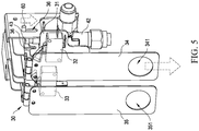
- the ignition operator 34 and the shut-down operator 35 are formed with an openings 341, 351, respectively, to allow a user's finger to insert into the openings 341, 351 to pull the ignition operator 34 and the shut-down operator 35 downward.
- a user may operate the ignition operator 34 to contact and press the fuel gas valve rod 43 and the ignition switch 32, so as to open the valve switch 42 to supply fuel gas to the burner 40 and also activate the ignition circuit to cause successive shootings of the ignition pin 22 of the pilot fire assembly 20 to ignite and set a fire on the burner 40.
- the user may operate the shut-down operator 35 to contact and press the shut-down switch 33, so as to cut off a signal of the thermocouple 23 and thus cut off the supply of fuel gas to the heater structure of this invention.
- this invention provides a structure having excellent functionality and ensuring convenience of operating heater switches.
- the protective cover 50 guides a pilot fire generated by the pilot fire assembly 20 toward the burner 40, and allows air to be introduced from the front side to support flaming of the pilot fire and reduce undesired influence imposed on the pilot fire by external airflows.
- the present invention also provides another structure, in which the ignition operator 34 and the shut-down operator 35 have ends that are connected to each other and the connected ends are movably pivoted to a support point or fulcrum 37 provided on the mounting frame 31, so that the ignition operator 34 and the shut-down operator 35 collectively form an see-saw arrangement, which prevents the ignition operator 34 and the shut-down operator 35 from being activated and operated at the same time and thus providing a foolproof function.
- the ignition operator 34 and the shut-down operator 35 are arranged to form a 90-degree angle therebetween to allow for easy operation of the switches of the heater by the user.
Landscapes
- Engineering & Computer Science (AREA)
- Chemical & Material Sciences (AREA)
- Combustion & Propulsion (AREA)
- Mechanical Engineering (AREA)
- General Engineering & Computer Science (AREA)
- Physics & Mathematics (AREA)
- Thermal Sciences (AREA)
- Direct Air Heating By Heater Or Combustion Gas (AREA)
Claims (9)
- Structure de dispositif de chauffage, comprenant :un corps de dispositif de chauffage (10), qui comprend un brûleur (40), qui est connecté à un tube d'alimentation en gaz (41), et un commutateur de soupape (42), qui est adapté pour se connecter à une source d'alimentation en gaz combustible, le commutateur de soupape (42) étant fourni sur un côté supérieur de celui-ci avec une tige de soupape de gaz combustible (43), qui fonctionne pour commander le commutateur de soupape (42) de fournir ou non du gaz combustible au brûleur (40) ;un ensemble d'incendie pilote (20), qui est monté sur le corps de dispositif de chauffage (10) à un emplacement adjacent au brûleur (40), l'ensemble d'incendie pilote (20) comprenant un tube de flamme pilote (21), une broche d'allumage (22) et un thermocouple (23), l'ensemble d'incendie pilote (20) étant recouvert et logé par un revêtement protecteur (50), le revêtement protecteur (50) étant formé avec une pluralité de trous de ventilation (51), un espace de guidage étant formé entre un côté du revêtement protecteur (50) et le corps de dispositif de chauffage (10) ; etune unité de commutateur (30), qui est montée par un cadre de montage (31) sur le commutateur de soupape (42), le cadre de montage (31) comprenant un commutateur d'allumage (32) connecté à un circuit d'allumage de la broche d'allumage (22), un commutateur d'arrêt (33) connecté à un circuit du thermocouple (23), un opérateur d'allumage (34) et un opérateur d'arrêt (35), où l'opérateur d'allumage (34) et l'opérateur d'arrêt (35) ont chacun une extrémité mobile montée sur le cadre de montage (31) pour former un agencement pivotant ; le commutateur d'allumage (32) et la tige de soupape de gaz combustible (43) sont agencés au-dessous de l'opérateur d'allumage (34) afin de pouvoir être mis en contact et appuyés par l'opérateur d'allumage (34) ; et le commutateur d'arrêt (33) est agencé au-dessous de l'opérateur d'arrêt (35) afin de pouvoir être mis en contact et appuyé par l'opérateur d'arrêt (35).
- Structure de dispositif de chauffage selon la revendication 1, où une plaque de guidage de débit (12) est agencée à un côté inférieur d'une partie avant du corps de dispositif de chauffage (10) pour guider des débits d'air vers un côté avant du brûleur (40) de sorte qu'ils se déplacent vers le haut.
- Structure de dispositif de chauffage selon la revendication 1, où la pluralité de trous de ventilation (51) du revêtement protecteur (50) est située sur une partie de surface du revêtement protecteur (50) qui se trouve à l'avant de l'ensemble d'incendie pilote (20) pour faire office de trous d'alimentation d'air.
- Structure de dispositif de chauffage selon la revendication 1, où le commutateur d'allumage (32) et le commutateur d'arrêt (33) comprennent chacun un micro-commutateur.
- Structure de dispositif de chauffage selon la revendication 1, où une barre ronde (60) est agencée entre un côté supérieur de la tige de soupape de gaz combustible (43) et un côté inférieur de l'opérateur d'allumage (34) et le cadre de montage (31) est formé avec deux fentes de protection (36) qui sont opposées et correspondent l'une à l'autre, deux extrémités de la barre ronde (60) étant reçues dans les fentes de protection (36) d'une manière mobile, où l'opérateur d'allumage (34), lors de l'oscillation vers le bas, appuie sur la barre ronde (60) pour enfoncer la tige de soupape de gaz combustible (43).
- Structure de dispositif de chauffage selon la revendication 1, où l'opérateur d'allumage (34) et l'opérateur d'arrêt (35) sont montés sur le cadre de montage (31) de manière mobile par pivotement et sont chaque structurés comme une plaque en forme de L inversée.
- Structure de dispositif de chauffage selon la revendication 6, où l'opérateur d'allumage (34) et l'opérateur d'arrêt (35) sont formés avec des ouvertures (341, 351) pour une opération de traction de l'opérateur d'allumage (34) et de l'opérateur d'arrêt (35) vers le bas.
- Structure de dispositif de chauffage selon la revendication 1, où les extrémités de l'opérateur d'allumage (34) et de l'opérateur d'arrêt (35) ont des extrémités connectées l'une à l'autre et sont couplées par pivotement à un point d'appui formé sur le cadre de montage (31) de telle sorte que l'opérateur d'allumage (34) et l'opérateur d'arrêt (35) forment collectivement un agencement de type balançoire.
- Structure de dispositif de chauffage selon la revendication 1, où l'opérateur d'allumage (34) et l'opérateur d'arrêt (35) sont agencés de manière à former un angle de 90 degrés entre eux.
Applications Claiming Priority (1)
| Application Number | Priority Date | Filing Date | Title |
|---|---|---|---|
| US16/245,263 US10739036B2 (en) | 2019-01-11 | 2019-01-11 | Heater structure |
Publications (2)
| Publication Number | Publication Date |
|---|---|
| EP3680552A1 EP3680552A1 (fr) | 2020-07-15 |
| EP3680552B1 true EP3680552B1 (fr) | 2021-04-28 |
Family
ID=68655285
Family Applications (1)
| Application Number | Title | Priority Date | Filing Date |
|---|---|---|---|
| EP19211081.5A Active EP3680552B1 (fr) | 2019-01-11 | 2019-11-25 | Structure de dispositif de chauffage |
Country Status (2)
| Country | Link |
|---|---|
| US (1) | US10739036B2 (fr) |
| EP (1) | EP3680552B1 (fr) |
Families Citing this family (1)
| Publication number | Priority date | Publication date | Assignee | Title |
|---|---|---|---|---|
| IT202100012668A1 (it) * | 2021-05-17 | 2022-11-17 | Beckett Thermal Solutions S R L | Bruciatore |
Family Cites Families (4)
| Publication number | Priority date | Publication date | Assignee | Title |
|---|---|---|---|---|
| GB2233756B (en) * | 1989-07-06 | 1993-03-31 | Willey Robinson Ltd | Controls for gas heating appliances |
| GB9407266D0 (en) * | 1994-04-13 | 1994-06-08 | Valor Ltd | Improvements relating to the control of gas fires |
| US6640802B2 (en) * | 2001-12-14 | 2003-11-04 | Op Controls Spa | Device for manual actuation of a gas distribution valve connected to a burner |
| US7654820B2 (en) * | 2006-12-22 | 2010-02-02 | David Deng | Control valves for heaters and fireplace devices |
-
2019
- 2019-01-11 US US16/245,263 patent/US10739036B2/en active Active
- 2019-11-25 EP EP19211081.5A patent/EP3680552B1/fr active Active
Non-Patent Citations (1)
| Title |
|---|
| None * |
Also Published As
| Publication number | Publication date |
|---|---|
| US20200224928A1 (en) | 2020-07-16 |
| EP3680552A1 (fr) | 2020-07-15 |
| US10739036B2 (en) | 2020-08-11 |
Similar Documents
| Publication | Publication Date | Title |
|---|---|---|
| CN201137968Y (zh) | 防风点火枪 | |
| US10443843B2 (en) | Safety device for gas burner | |
| EP3098517B1 (fr) | Ensemble de brûleurs | |
| US20090159068A1 (en) | Fuel-fired barbecue | |
| US5327879A (en) | Cooking apparatus with supplemental heat source | |
| EP3680552B1 (fr) | Structure de dispositif de chauffage | |
| JP5079861B2 (ja) | ガスコンロ | |
| US11747016B2 (en) | All-purpose gas stove structure capable of increasing air intake thereof | |
| AU2019200214B1 (en) | Heater structure | |
| US6553986B1 (en) | Burner for a gas barbecue grill | |
| CN110779050B (zh) | 燃气灶、燃气灶用燃烧器的炉头及燃烧器 | |
| US2538222A (en) | Safety control gas burner system | |
| JP5976455B2 (ja) | 加熱調理器 | |
| EP2531774B1 (fr) | Minuterie pour un brûleur à gaz pour appareil ménager | |
| US1745178A (en) | Liquid-fuel-burner control | |
| JP7079957B2 (ja) | コンロ | |
| CN209569819U (zh) | 暖炉结构 | |
| US20060105282A1 (en) | Disposable electronic windproof lighter | |
| CN219083183U (zh) | 一种燃烧控制模块及具有其的卡式炉 | |
| JP5530303B2 (ja) | ガスこんろの点消火ボタン | |
| US2649524A (en) | Thermally responsive oven burner control unit | |
| KR102032272B1 (ko) | 취반기용 점화장치 | |
| KR200353295Y1 (ko) | 보조노즐을 갖는 가스버너 | |
| US2022033A (en) | Heating system | |
| US782551A (en) | Ignition device for central-draft lamps. |
Legal Events
| Date | Code | Title | Description |
|---|---|---|---|
| PUAI | Public reference made under article 153(3) epc to a published international application that has entered the european phase |
Free format text: ORIGINAL CODE: 0009012 |
|
| STAA | Information on the status of an ep patent application or granted ep patent |
Free format text: STATUS: REQUEST FOR EXAMINATION WAS MADE |
|
| 17P | Request for examination filed |
Effective date: 20191125 |
|
| AK | Designated contracting states |
Kind code of ref document: A1 Designated state(s): AL AT BE BG CH CY CZ DE DK EE ES FI FR GB GR HR HU IE IS IT LI LT LU LV MC MK MT NL NO PL PT RO RS SE SI SK SM TR |
|
| AX | Request for extension of the european patent |
Extension state: BA ME |
|
| GRAP | Despatch of communication of intention to grant a patent |
Free format text: ORIGINAL CODE: EPIDOSNIGR1 |
|
| STAA | Information on the status of an ep patent application or granted ep patent |
Free format text: STATUS: GRANT OF PATENT IS INTENDED |
|
| RIC1 | Information provided on ipc code assigned before grant |
Ipc: F24D 15/00 20060101ALI20201130BHEP Ipc: F23N 5/24 20060101ALI20201130BHEP Ipc: F23Q 3/00 20060101ALI20201130BHEP Ipc: F24D 19/00 20060101ALI20201130BHEP Ipc: F24C 3/04 20060101ALI20201130BHEP Ipc: F23D 14/26 20060101ALI20201130BHEP Ipc: F23D 14/14 20060101ALI20201130BHEP Ipc: F23N 1/00 20060101AFI20201130BHEP Ipc: F23Q 9/00 20060101ALI20201130BHEP |
|
| INTG | Intention to grant announced |
Effective date: 20201218 |
|
| GRAS | Grant fee paid |
Free format text: ORIGINAL CODE: EPIDOSNIGR3 |
|
| GRAA | (expected) grant |
Free format text: ORIGINAL CODE: 0009210 |
|
| STAA | Information on the status of an ep patent application or granted ep patent |
Free format text: STATUS: THE PATENT HAS BEEN GRANTED |
|
| AK | Designated contracting states |
Kind code of ref document: B1 Designated state(s): AL AT BE BG CH CY CZ DE DK EE ES FI FR GB GR HR HU IE IS IT LI LT LU LV MC MK MT NL NO PL PT RO RS SE SI SK SM TR |
|
| REG | Reference to a national code |
Ref country code: GB Ref legal event code: FG4D |
|
| REG | Reference to a national code |
Ref country code: CH Ref legal event code: EP |
|
| REG | Reference to a national code |
Ref country code: AT Ref legal event code: REF Ref document number: 1387463 Country of ref document: AT Kind code of ref document: T Effective date: 20210515 |
|
| REG | Reference to a national code |
Ref country code: DE Ref legal event code: R096 Ref document number: 602019004278 Country of ref document: DE |
|
| REG | Reference to a national code |
Ref country code: IE Ref legal event code: FG4D |
|
| REG | Reference to a national code |
Ref country code: LT Ref legal event code: MG9D |
|
| REG | Reference to a national code |
Ref country code: AT Ref legal event code: MK05 Ref document number: 1387463 Country of ref document: AT Kind code of ref document: T Effective date: 20210428 |
|
| PG25 | Lapsed in a contracting state [announced via postgrant information from national office to epo] |
Ref country code: FI Free format text: LAPSE BECAUSE OF FAILURE TO SUBMIT A TRANSLATION OF THE DESCRIPTION OR TO PAY THE FEE WITHIN THE PRESCRIBED TIME-LIMIT Effective date: 20210428 Ref country code: HR Free format text: LAPSE BECAUSE OF FAILURE TO SUBMIT A TRANSLATION OF THE DESCRIPTION OR TO PAY THE FEE WITHIN THE PRESCRIBED TIME-LIMIT Effective date: 20210428 Ref country code: LT Free format text: LAPSE BECAUSE OF FAILURE TO SUBMIT A TRANSLATION OF THE DESCRIPTION OR TO PAY THE FEE WITHIN THE PRESCRIBED TIME-LIMIT Effective date: 20210428 Ref country code: BG Free format text: LAPSE BECAUSE OF FAILURE TO SUBMIT A TRANSLATION OF THE DESCRIPTION OR TO PAY THE FEE WITHIN THE PRESCRIBED TIME-LIMIT Effective date: 20210728 Ref country code: AT Free format text: LAPSE BECAUSE OF FAILURE TO SUBMIT A TRANSLATION OF THE DESCRIPTION OR TO PAY THE FEE WITHIN THE PRESCRIBED TIME-LIMIT Effective date: 20210428 Ref country code: NL Free format text: LAPSE BECAUSE OF FAILURE TO SUBMIT A TRANSLATION OF THE DESCRIPTION OR TO PAY THE FEE WITHIN THE PRESCRIBED TIME-LIMIT Effective date: 20210428 |
|
| PG25 | Lapsed in a contracting state [announced via postgrant information from national office to epo] |
Ref country code: IS Free format text: LAPSE BECAUSE OF FAILURE TO SUBMIT A TRANSLATION OF THE DESCRIPTION OR TO PAY THE FEE WITHIN THE PRESCRIBED TIME-LIMIT Effective date: 20210828 Ref country code: GR Free format text: LAPSE BECAUSE OF FAILURE TO SUBMIT A TRANSLATION OF THE DESCRIPTION OR TO PAY THE FEE WITHIN THE PRESCRIBED TIME-LIMIT Effective date: 20210729 Ref country code: PL Free format text: LAPSE BECAUSE OF FAILURE TO SUBMIT A TRANSLATION OF THE DESCRIPTION OR TO PAY THE FEE WITHIN THE PRESCRIBED TIME-LIMIT Effective date: 20210428 Ref country code: LV Free format text: LAPSE BECAUSE OF FAILURE TO SUBMIT A TRANSLATION OF THE DESCRIPTION OR TO PAY THE FEE WITHIN THE PRESCRIBED TIME-LIMIT Effective date: 20210428 Ref country code: NO Free format text: LAPSE BECAUSE OF FAILURE TO SUBMIT A TRANSLATION OF THE DESCRIPTION OR TO PAY THE FEE WITHIN THE PRESCRIBED TIME-LIMIT Effective date: 20210728 Ref country code: SE Free format text: LAPSE BECAUSE OF FAILURE TO SUBMIT A TRANSLATION OF THE DESCRIPTION OR TO PAY THE FEE WITHIN THE PRESCRIBED TIME-LIMIT Effective date: 20210428 Ref country code: RS Free format text: LAPSE BECAUSE OF FAILURE TO SUBMIT A TRANSLATION OF THE DESCRIPTION OR TO PAY THE FEE WITHIN THE PRESCRIBED TIME-LIMIT Effective date: 20210428 Ref country code: PT Free format text: LAPSE BECAUSE OF FAILURE TO SUBMIT A TRANSLATION OF THE DESCRIPTION OR TO PAY THE FEE WITHIN THE PRESCRIBED TIME-LIMIT Effective date: 20210830 |
|
| REG | Reference to a national code |
Ref country code: NL Ref legal event code: MP Effective date: 20210428 |
|
| PG25 | Lapsed in a contracting state [announced via postgrant information from national office to epo] |
Ref country code: ES Free format text: LAPSE BECAUSE OF FAILURE TO SUBMIT A TRANSLATION OF THE DESCRIPTION OR TO PAY THE FEE WITHIN THE PRESCRIBED TIME-LIMIT Effective date: 20210428 Ref country code: EE Free format text: LAPSE BECAUSE OF FAILURE TO SUBMIT A TRANSLATION OF THE DESCRIPTION OR TO PAY THE FEE WITHIN THE PRESCRIBED TIME-LIMIT Effective date: 20210428 Ref country code: SK Free format text: LAPSE BECAUSE OF FAILURE TO SUBMIT A TRANSLATION OF THE DESCRIPTION OR TO PAY THE FEE WITHIN THE PRESCRIBED TIME-LIMIT Effective date: 20210428 Ref country code: RO Free format text: LAPSE BECAUSE OF FAILURE TO SUBMIT A TRANSLATION OF THE DESCRIPTION OR TO PAY THE FEE WITHIN THE PRESCRIBED TIME-LIMIT Effective date: 20210428 Ref country code: SM Free format text: LAPSE BECAUSE OF FAILURE TO SUBMIT A TRANSLATION OF THE DESCRIPTION OR TO PAY THE FEE WITHIN THE PRESCRIBED TIME-LIMIT Effective date: 20210428 Ref country code: DK Free format text: LAPSE BECAUSE OF FAILURE TO SUBMIT A TRANSLATION OF THE DESCRIPTION OR TO PAY THE FEE WITHIN THE PRESCRIBED TIME-LIMIT Effective date: 20210428 Ref country code: CZ Free format text: LAPSE BECAUSE OF FAILURE TO SUBMIT A TRANSLATION OF THE DESCRIPTION OR TO PAY THE FEE WITHIN THE PRESCRIBED TIME-LIMIT Effective date: 20210428 |
|
| REG | Reference to a national code |
Ref country code: DE Ref legal event code: R097 Ref document number: 602019004278 Country of ref document: DE |
|
| PLBE | No opposition filed within time limit |
Free format text: ORIGINAL CODE: 0009261 |
|
| STAA | Information on the status of an ep patent application or granted ep patent |
Free format text: STATUS: NO OPPOSITION FILED WITHIN TIME LIMIT |
|
| 26N | No opposition filed |
Effective date: 20220131 |
|
| PG25 | Lapsed in a contracting state [announced via postgrant information from national office to epo] |
Ref country code: IS Free format text: LAPSE BECAUSE OF FAILURE TO SUBMIT A TRANSLATION OF THE DESCRIPTION OR TO PAY THE FEE WITHIN THE PRESCRIBED TIME-LIMIT Effective date: 20210828 Ref country code: AL Free format text: LAPSE BECAUSE OF FAILURE TO SUBMIT A TRANSLATION OF THE DESCRIPTION OR TO PAY THE FEE WITHIN THE PRESCRIBED TIME-LIMIT Effective date: 20210428 |
|
| PG25 | Lapsed in a contracting state [announced via postgrant information from national office to epo] |
Ref country code: MC Free format text: LAPSE BECAUSE OF FAILURE TO SUBMIT A TRANSLATION OF THE DESCRIPTION OR TO PAY THE FEE WITHIN THE PRESCRIBED TIME-LIMIT Effective date: 20210428 |
|
| PG25 | Lapsed in a contracting state [announced via postgrant information from national office to epo] |
Ref country code: LU Free format text: LAPSE BECAUSE OF NON-PAYMENT OF DUE FEES Effective date: 20211125 Ref country code: IT Free format text: LAPSE BECAUSE OF FAILURE TO SUBMIT A TRANSLATION OF THE DESCRIPTION OR TO PAY THE FEE WITHIN THE PRESCRIBED TIME-LIMIT Effective date: 20210428 Ref country code: BE Free format text: LAPSE BECAUSE OF NON-PAYMENT OF DUE FEES Effective date: 20211130 |
|
| REG | Reference to a national code |
Ref country code: BE Ref legal event code: MM Effective date: 20211130 |
|
| PG25 | Lapsed in a contracting state [announced via postgrant information from national office to epo] |
Ref country code: IE Free format text: LAPSE BECAUSE OF NON-PAYMENT OF DUE FEES Effective date: 20211125 |
|
| PG25 | Lapsed in a contracting state [announced via postgrant information from national office to epo] |
Ref country code: CY Free format text: LAPSE BECAUSE OF FAILURE TO SUBMIT A TRANSLATION OF THE DESCRIPTION OR TO PAY THE FEE WITHIN THE PRESCRIBED TIME-LIMIT Effective date: 20210428 |
|
| REG | Reference to a national code |
Ref country code: CH Ref legal event code: PL |
|
| PG25 | Lapsed in a contracting state [announced via postgrant information from national office to epo] |
Ref country code: LI Free format text: LAPSE BECAUSE OF NON-PAYMENT OF DUE FEES Effective date: 20221130 Ref country code: HU Free format text: LAPSE BECAUSE OF FAILURE TO SUBMIT A TRANSLATION OF THE DESCRIPTION OR TO PAY THE FEE WITHIN THE PRESCRIBED TIME-LIMIT; INVALID AB INITIO Effective date: 20191125 Ref country code: CH Free format text: LAPSE BECAUSE OF NON-PAYMENT OF DUE FEES Effective date: 20221130 |
|
| PG25 | Lapsed in a contracting state [announced via postgrant information from national office to epo] |
Ref country code: MK Free format text: LAPSE BECAUSE OF FAILURE TO SUBMIT A TRANSLATION OF THE DESCRIPTION OR TO PAY THE FEE WITHIN THE PRESCRIBED TIME-LIMIT Effective date: 20210428 |
|
| PG25 | Lapsed in a contracting state [announced via postgrant information from national office to epo] |
Ref country code: TR Free format text: LAPSE BECAUSE OF FAILURE TO SUBMIT A TRANSLATION OF THE DESCRIPTION OR TO PAY THE FEE WITHIN THE PRESCRIBED TIME-LIMIT Effective date: 20210428 |
|
| GBPC | Gb: european patent ceased through non-payment of renewal fee |
Effective date: 20231125 |
|
| PG25 | Lapsed in a contracting state [announced via postgrant information from national office to epo] |
Ref country code: MT Free format text: LAPSE BECAUSE OF FAILURE TO SUBMIT A TRANSLATION OF THE DESCRIPTION OR TO PAY THE FEE WITHIN THE PRESCRIBED TIME-LIMIT Effective date: 20210428 |
|
| PG25 | Lapsed in a contracting state [announced via postgrant information from national office to epo] |
Ref country code: GB Free format text: LAPSE BECAUSE OF NON-PAYMENT OF DUE FEES Effective date: 20231125 |
|
| PG25 | Lapsed in a contracting state [announced via postgrant information from national office to epo] |
Ref country code: GB Free format text: LAPSE BECAUSE OF NON-PAYMENT OF DUE FEES Effective date: 20231125 |
|
| PGFP | Annual fee paid to national office [announced via postgrant information from national office to epo] |
Ref country code: DE Payment date: 20250819 Year of fee payment: 7 |
|
| PGFP | Annual fee paid to national office [announced via postgrant information from national office to epo] |
Ref country code: FR Payment date: 20251126 Year of fee payment: 7 |