EP3680500B1 - Palier à roulement équipé d'un dispositif d étanchéité - Google Patents
Palier à roulement équipé d'un dispositif d étanchéité Download PDFInfo
- Publication number
- EP3680500B1 EP3680500B1 EP20150600.3A EP20150600A EP3680500B1 EP 3680500 B1 EP3680500 B1 EP 3680500B1 EP 20150600 A EP20150600 A EP 20150600A EP 3680500 B1 EP3680500 B1 EP 3680500B1
- Authority
- EP
- European Patent Office
- Prior art keywords
- roller bearing
- bearing according
- deflector
- opening
- angle
- Prior art date
- Legal status (The legal status is an assumption and is not a legal conclusion. Google has not performed a legal analysis and makes no representation as to the accuracy of the status listed.)
- Active
Links
Images
Classifications
-
- F—MECHANICAL ENGINEERING; LIGHTING; HEATING; WEAPONS; BLASTING
- F16—ENGINEERING ELEMENTS AND UNITS; GENERAL MEASURES FOR PRODUCING AND MAINTAINING EFFECTIVE FUNCTIONING OF MACHINES OR INSTALLATIONS; THERMAL INSULATION IN GENERAL
- F16C—SHAFTS; FLEXIBLE SHAFTS; ELEMENTS OR CRANKSHAFT MECHANISMS; ROTARY BODIES OTHER THAN GEARING ELEMENTS; BEARINGS
- F16C19/00—Bearings with rolling contact, for exclusively rotary movement
- F16C19/02—Bearings with rolling contact, for exclusively rotary movement with bearing balls essentially of the same size in one or more circular rows
- F16C19/14—Bearings with rolling contact, for exclusively rotary movement with bearing balls essentially of the same size in one or more circular rows for both radial and axial load
- F16C19/16—Bearings with rolling contact, for exclusively rotary movement with bearing balls essentially of the same size in one or more circular rows for both radial and axial load with a single row of balls
-
- F—MECHANICAL ENGINEERING; LIGHTING; HEATING; WEAPONS; BLASTING
- F16—ENGINEERING ELEMENTS AND UNITS; GENERAL MEASURES FOR PRODUCING AND MAINTAINING EFFECTIVE FUNCTIONING OF MACHINES OR INSTALLATIONS; THERMAL INSULATION IN GENERAL
- F16C—SHAFTS; FLEXIBLE SHAFTS; ELEMENTS OR CRANKSHAFT MECHANISMS; ROTARY BODIES OTHER THAN GEARING ELEMENTS; BEARINGS
- F16C33/00—Parts of bearings; Special methods for making bearings or parts thereof
- F16C33/72—Sealings
- F16C33/76—Sealings of ball or roller bearings
- F16C33/78—Sealings of ball or roller bearings with a diaphragm, disc, or ring, with or without resilient members
- F16C33/7816—Details of the sealing or parts thereof, e.g. geometry, material
- F16C33/782—Details of the sealing or parts thereof, e.g. geometry, material of the sealing region
-
- F—MECHANICAL ENGINEERING; LIGHTING; HEATING; WEAPONS; BLASTING
- F16—ENGINEERING ELEMENTS AND UNITS; GENERAL MEASURES FOR PRODUCING AND MAINTAINING EFFECTIVE FUNCTIONING OF MACHINES OR INSTALLATIONS; THERMAL INSULATION IN GENERAL
- F16C—SHAFTS; FLEXIBLE SHAFTS; ELEMENTS OR CRANKSHAFT MECHANISMS; ROTARY BODIES OTHER THAN GEARING ELEMENTS; BEARINGS
- F16C33/00—Parts of bearings; Special methods for making bearings or parts thereof
- F16C33/72—Sealings
- F16C33/76—Sealings of ball or roller bearings
- F16C33/78—Sealings of ball or roller bearings with a diaphragm, disc, or ring, with or without resilient members
- F16C33/7816—Details of the sealing or parts thereof, e.g. geometry, material
- F16C33/782—Details of the sealing or parts thereof, e.g. geometry, material of the sealing region
- F16C33/7823—Details of the sealing or parts thereof, e.g. geometry, material of the sealing region of sealing lips
-
- F—MECHANICAL ENGINEERING; LIGHTING; HEATING; WEAPONS; BLASTING
- F16—ENGINEERING ELEMENTS AND UNITS; GENERAL MEASURES FOR PRODUCING AND MAINTAINING EFFECTIVE FUNCTIONING OF MACHINES OR INSTALLATIONS; THERMAL INSULATION IN GENERAL
- F16C—SHAFTS; FLEXIBLE SHAFTS; ELEMENTS OR CRANKSHAFT MECHANISMS; ROTARY BODIES OTHER THAN GEARING ELEMENTS; BEARINGS
- F16C33/00—Parts of bearings; Special methods for making bearings or parts thereof
- F16C33/72—Sealings
- F16C33/76—Sealings of ball or roller bearings
- F16C33/78—Sealings of ball or roller bearings with a diaphragm, disc, or ring, with or without resilient members
- F16C33/7816—Details of the sealing or parts thereof, e.g. geometry, material
- F16C33/783—Details of the sealing or parts thereof, e.g. geometry, material of the mounting region
-
- F—MECHANICAL ENGINEERING; LIGHTING; HEATING; WEAPONS; BLASTING
- F16—ENGINEERING ELEMENTS AND UNITS; GENERAL MEASURES FOR PRODUCING AND MAINTAINING EFFECTIVE FUNCTIONING OF MACHINES OR INSTALLATIONS; THERMAL INSULATION IN GENERAL
- F16C—SHAFTS; FLEXIBLE SHAFTS; ELEMENTS OR CRANKSHAFT MECHANISMS; ROTARY BODIES OTHER THAN GEARING ELEMENTS; BEARINGS
- F16C33/00—Parts of bearings; Special methods for making bearings or parts thereof
- F16C33/72—Sealings
- F16C33/76—Sealings of ball or roller bearings
- F16C33/78—Sealings of ball or roller bearings with a diaphragm, disc, or ring, with or without resilient members
- F16C33/7869—Sealings of ball or roller bearings with a diaphragm, disc, or ring, with or without resilient members mounted with a cylindrical portion to the inner surface of the outer race and having a radial portion extending inward
- F16C33/7873—Sealings of ball or roller bearings with a diaphragm, disc, or ring, with or without resilient members mounted with a cylindrical portion to the inner surface of the outer race and having a radial portion extending inward with a single sealing ring of generally L-shaped cross-section
- F16C33/7876—Sealings of ball or roller bearings with a diaphragm, disc, or ring, with or without resilient members mounted with a cylindrical portion to the inner surface of the outer race and having a radial portion extending inward with a single sealing ring of generally L-shaped cross-section with sealing lips
-
- F—MECHANICAL ENGINEERING; LIGHTING; HEATING; WEAPONS; BLASTING
- F16—ENGINEERING ELEMENTS AND UNITS; GENERAL MEASURES FOR PRODUCING AND MAINTAINING EFFECTIVE FUNCTIONING OF MACHINES OR INSTALLATIONS; THERMAL INSULATION IN GENERAL
- F16C—SHAFTS; FLEXIBLE SHAFTS; ELEMENTS OR CRANKSHAFT MECHANISMS; ROTARY BODIES OTHER THAN GEARING ELEMENTS; BEARINGS
- F16C33/00—Parts of bearings; Special methods for making bearings or parts thereof
- F16C33/72—Sealings
- F16C33/76—Sealings of ball or roller bearings
- F16C33/78—Sealings of ball or roller bearings with a diaphragm, disc, or ring, with or without resilient members
- F16C33/7886—Sealings of ball or roller bearings with a diaphragm, disc, or ring, with or without resilient members mounted outside the gap between the inner and outer races, e.g. sealing rings mounted to an end face or outer surface of a race
-
- F—MECHANICAL ENGINEERING; LIGHTING; HEATING; WEAPONS; BLASTING
- F16—ENGINEERING ELEMENTS AND UNITS; GENERAL MEASURES FOR PRODUCING AND MAINTAINING EFFECTIVE FUNCTIONING OF MACHINES OR INSTALLATIONS; THERMAL INSULATION IN GENERAL
- F16C—SHAFTS; FLEXIBLE SHAFTS; ELEMENTS OR CRANKSHAFT MECHANISMS; ROTARY BODIES OTHER THAN GEARING ELEMENTS; BEARINGS
- F16C33/00—Parts of bearings; Special methods for making bearings or parts thereof
- F16C33/72—Sealings
- F16C33/76—Sealings of ball or roller bearings
- F16C33/78—Sealings of ball or roller bearings with a diaphragm, disc, or ring, with or without resilient members
- F16C33/7889—Sealings of ball or roller bearings with a diaphragm, disc, or ring, with or without resilient members mounted to an inner race and extending toward the outer race
-
- F—MECHANICAL ENGINEERING; LIGHTING; HEATING; WEAPONS; BLASTING
- F16—ENGINEERING ELEMENTS AND UNITS; GENERAL MEASURES FOR PRODUCING AND MAINTAINING EFFECTIVE FUNCTIONING OF MACHINES OR INSTALLATIONS; THERMAL INSULATION IN GENERAL
- F16C—SHAFTS; FLEXIBLE SHAFTS; ELEMENTS OR CRANKSHAFT MECHANISMS; ROTARY BODIES OTHER THAN GEARING ELEMENTS; BEARINGS
- F16C33/00—Parts of bearings; Special methods for making bearings or parts thereof
- F16C33/72—Sealings
- F16C33/76—Sealings of ball or roller bearings
- F16C33/80—Labyrinth sealings
-
- F—MECHANICAL ENGINEERING; LIGHTING; HEATING; WEAPONS; BLASTING
- F16—ENGINEERING ELEMENTS AND UNITS; GENERAL MEASURES FOR PRODUCING AND MAINTAINING EFFECTIVE FUNCTIONING OF MACHINES OR INSTALLATIONS; THERMAL INSULATION IN GENERAL
- F16C—SHAFTS; FLEXIBLE SHAFTS; ELEMENTS OR CRANKSHAFT MECHANISMS; ROTARY BODIES OTHER THAN GEARING ELEMENTS; BEARINGS
- F16C2326/00—Articles relating to transporting
- F16C2326/01—Parts of vehicles in general
- F16C2326/02—Wheel hubs or castors
Definitions
- the invention relates to a rolling bearing comprising two members and rolling bodies arranged in a bearing space formed between said members to allow their relative rotation around an axis.
- a bearing according to the invention allows the mounting of a driving or non-driving wheel of a motor vehicle, one member being rotating and comprising means for fixing the wheel while the other member is fixed and comprises means fixing on a suspension element of the vehicle.
- At least one side of the rolling space can be equipped with a device for sealing.
- the sealing device may comprise an armature integral with a first member and a wall integral with the second member, said armature being equipped with a dynamic sealing element which has at least one lip arranged in frictional contact on a section of the wall.
- the document WO-2017/055724 describes a rolling bearing of which at least one side of the rolling space is equipped with a sealing device comprising two armatures integral with one member respectively, and comprising respectively an upstream crown and a downstream crown which extend axially in being arranged facing radially to form a sealing chamber, at least one crown being equipped with a dynamic sealing element which has at least one lip disposed in said chamber while being in frictional contact on the other crown.
- deflectors may be added to form an inlet baffle which is arranged to limit the exchanges between the rolling space and the outside, in particular at the level of the friction section.
- the invention aims to improve the prior art by proposing in particular a rolling bearing equipped with a sealing device whose sealing interface is optimized, in particular by being arranged to facilitate the extraction by gravity of any pollutants entered in said interface.
- the invention proposes a rolling bearing according to claim 1.
- a rolling bearing is described below, in particular for mounting a driving or non-driving wheel of a motor vehicle.
- the bearing comprises two members, namely in the figures a first member 1 disposed externally while being fixed and a second member 2 disposed internally by being rotating.
- the wheel is intended to be associated with the interior member 2 and the exterior member 1 may have means for fixing the bearing to a suspension element of the motor vehicle.
- each member 1, 2 may have two rolling tracks 1a, 2a spaced axially so as to form in the rolling space 3 two rolling tracks in which are arranged respectively a row of rolling bodies 4, said bodies rollers for example in the form of balls which are held in a row by means of a retention cage 5.
- the invention is not limited to one embodiment of the bearing, in particular with respect to the geometry of the rolling bodies 4, to the geometry and/or to the relative arrangement of the fixed and rotating members.
- the figures show one side of the rolling space 3 which has an annular chamber 6 in communication with the outside via an annular opening 7 formed between the members 1, 2.
- the first member 1 has an extension 8 delimiting the opening 7 with an outer wall 9 of the second member 2, said extension being in the form of a ring of substantially rectangular section delimited by a radial wall of end 8a, an outer axial wall 8b and an inner wall 8c extending mainly in the axial direction and on which a part of the raceway 1a is formed.
- the chamber 6 is equipped with a sealing device .
- the reinforcement 10 can be made of metallic material, in particular by bending a stamped sheet.
- the wall 12 is formed in the second member 2.
- the wall 12 can be formed on a part attached to the second member 2, said part also being able to have a structure similar to the armature 10, in particular being formed by bending a stamped sheet.
- the reinforcement 10 has a downstream sector 10a carrying the sealing element 11, said sector being arranged in the chamber 6 forming on either side an internal compartment 6a and an external compartment 6b.
- upstream and downstream are defined with respect to the direction of introduction of the pollutants into the opening 7, from the exterior towards the interior.
- exital and internal are defined with respect to the orientation of the bearing as shown, and refer to a disposition respectively on the left and on the right in the figures.
- the dynamic sealing is improved by providing that the sealing element 11 has two lips 11a, 11b arranged in the outer compartment 6b and in frictional contact at two spaced apart places of the wall 12.
- the sealing element 11 has two lips 11a, 11b arranged in the outer compartment 6b and in frictional contact at two spaced apart places of the wall 12.
- at least one lip 11a, 11b can form a sealing clearance with the wall 12.
- the downstream sector 10a has a U-shaped geometry formed by a substantially axial bottom 13a bordered by two walls - respectively internal 13b and external 13c - each having a radial height, the external wall 13c being extended by a deflector 11c of the element of sealing 11 which extends into the chamber 6 by separating with the U-shaped geometry the internal 6a and external 6b compartments.
- the U-shaped geometry makes it possible to form in the internal compartment 6a a zone for recovering external pollutants entering through the opening 7, the length of the bottom 13a and/or the height of the radial walls 13b, 13c being large enough to contain said pollutants in said zone, and thus limit their penetration into the external compartment 6b.
- the outer lip 11a has an outer end 25 in frictional contact on the radial section 12a being arranged along a diameter D which is greater than the diameter D' of the bottom 13a U-shaped geometry.
- the wall 12 has an outer section 12c connected to the radial section 12a by a fillet 18, said outer section bordering the chamber 6 over an axial depth from the opening 7 by forming with the deflector 11c a reduced sealing clearance 14 between said opening and said outer compartment.
- the deflector 11c has a free end 15 which is arranged radially opposite the outer section 12c, the sealing clearance 14 being formed between said free end and said outer section.
- the outer section 12c and the opening 7 have a common edge 16 with respect to which the free end 15 is set back axially, which makes it possible to prevent external pollutants coming from the opening 7 from flowing directly onto the deflector 11c, and thus to limit the risks of entry of said pollutants into the external compartment 6b.
- the deflector 11c has an outer face 17a which is arranged in the outer compartment 6b while being inclined towards the opening 7 by an angle ⁇ of between 10° and 80°, in particular between 40° and 60°, with respect to a radial direction.
- the external face 17a forms a slope to guide any pollutants contained in the external compartment 6b towards the outside, which makes it possible to facilitate the evacuation by centrifugation and/or gravity of said pollutants from said external compartment.
- the external section 12c is inclined externally by an angle ⁇ of less than 30° with respect to an axial direction.
- the angle ⁇ can be of the order of 45°.
- the sealing element 11 has a crown 11d disposed in the radial extension of the outer wall 13c, the deflector 11c extending from said crown.
- the crown 11d has a thickness greater than that of the deflector 11c so as to be able to place said deflector as close as possible to the outer section 12c, and therefore to reduce the dimensions of the sealing clearance 14, while limiting the radial height said deflector, in order to limit its deflection when pollutants flow over it
- the deflector 11c has an internal face 17b arranged in said internal compartment surrounding the bottom 13a of the U-shaped geometry.
- the internal face 17b is inclined towards the opening by an angle ⁇ of between 40° and 60° with respect to a radial direction, which makes it possible to guide towards the opening 7 any pollutants contained in the compartment. internal 6a.
- the angle ⁇ is measured with respect to an axial direction in the trigonometric direction, the angles ⁇ and ⁇ being measured in the anti-trigonometric direction with respect to a radial direction.
- the external 17a and internal 17b faces are inclined towards the opening 7 with respect to the radial direction of respectively one face of the crown 11d.
- the angle ⁇ of the internal face 17b is less than the angle ⁇ of the external face 17a in order to form a deflector of conical geometry which tapers from the crown 11c towards its free end 15.
- the internal face 17b is arranged substantially in alignment with the common edge 16 between the opening 7 and the external section 12c, which makes it possible to guide the pollutants from said internal face directly towards said opening.
- the common edge 16 has a chamfer with an angle ⁇ substantially equal to the angle ⁇ of the internal face 17b.
- the conical geometry of the wall 19b connecting the upstream 10b and downstream 10a sectors makes it possible to axially separate said downstream sector from the running space, but also to arrange the free end 15 of the deflector 11c set back axially of the opening 7, with the advantages mentioned previously.
- the outer sector 10b has a bead 22 which is placed to bear against the protrusion 8 to form a static seal.
- the outer wall 19c having a free edge 23 offset radially in order to allow contact between the bead 22 and the outer axial wall 8b which guarantees static sealing.
- the sealing element 11 can be associated by overmoulding with the reinforcement 10.
- the sealing element can be made of a flexible material, for example an elastomer, in particular based on butadiene nitrile (NBR) copolymer, optionally reinforced mechanically with fillers such as carbon black, hydrogenated NBR (HNBR), fluoropolymer or polyacrylate.
- NBR butadiene nitrile
Landscapes
- Engineering & Computer Science (AREA)
- General Engineering & Computer Science (AREA)
- Mechanical Engineering (AREA)
- Rolling Contact Bearings (AREA)
- Sealing Of Bearings (AREA)
Description
- L'invention concerne un palier à roulement comprenant deux organes et des corps roulants disposés dans un espace de roulement formé entre lesdits organes pour permettre leur rotation relative autour d'un axe.
- En particulier, l'invention s'applique aux paliers à roulement de véhicule automobile, notamment aux paliers de roue. De façon avantageuse, un palier suivant l'invention permet le montage d'une roue motrice ou non motrice de véhicule automobile, un organe étant tournant et comprenant des moyens de fixation de la roue tandis que l'autre organe est fixe et comprend des moyens de fixation sur un élément de suspension du véhicule.
- Pour empêcher d'une part les fuites de lubrifiant présent dans l'espace de roulement et d'autre part la contamination dudit espace avec des polluants extérieurs, au moins un côté de l'espace de roulement peut être équipé d'un dispositif d'étanchéité.
- En particulier, le dispositif d'étanchéité peut comprendre une armature solidaire d'un premier organe et une paroi solidaire du deuxième organe, ladite armature étant équipée d'un élément d'étanchéité dynamique qui présente au moins une lèvre disposée en contact frottant sur une section de la paroi.
- Le document
WO-2017/055724 décrit un palier à roulement dont au moins un côté de l'espace de roulement est équipé d'un dispositif d'étanchéité comprenant deux armatures solidaires de respectivement un organe, et comprenant respectivement une couronne amont et une couronne aval qui s'étendent axialement en étant disposées en regard radial pour former une chambre d'étanchéité, au moins une couronne étant équipée d'un élément d'étanchéité dynamique qui présente au moins une lèvre disposée dans ladite chambre en étant en contact frottant sur l'autre couronne. - Ce document décrit un palier à contact de roulement équipé d'un dispositif d'étanchéité comme décrit dans le préambule de la revendication indépendante annexée.
- Pour satisfaire aux cahiers des charges de plus en plus sévères relativement à l'étanchéité, notamment pour la validation des paliers de roue par les constructeurs automobiles, cette solution conduit à un couple de frottement important qui, outre l'impact négatif sur l'énergie nécessaire à la rotation du palier, provoque un niveau de température de fonctionnement élevé et donc une usure prématurée de la lèvre frottante. En outre, cette usure est d'autant plus rapide que des polluants peuvent rentrer au niveau de la section de frottement et y demeurer lors de la rotation.
- Pour tenter de résoudre ce problème, on peut proposer d'ajouter des déflecteurs pour former une chicane d'entrée qui est agencée pour limiter les échanges entre l'espace de roulement et l'extérieur, notamment au niveau de la section de frottement.
- En particulier, le document
WO-2018/192597 prévoit un palier à roulement dans lequel au moins un côté de l'espace de roulement présente une chambre annulaire en communication avec l'extérieur par une ouverture, ledit palier étant équipé d'un dispositif d'étanchéité tel que décrit précédemment, dans lequel : - l'armature présente un secteur aval disposé dans la chambre en formant de part et d'autre un compartiment interne, dans lequel débouche l'ouverture, et un compartiment externe en communication avec l'espace de roulement et dans lequel est disposée au moins une lèvre frottante, ledit secteur aval présentant une géométrie en U dont la paroi externe forme un déflecteur qui s'étend dans ladite chambre en séparant avec la géométrie en U les compartiments interne et externe ;
- la paroi d'étanchéité présente une section extérieure qui borde la chambre sur une profondeur axiale depuis l'ouverture en formant avec le déflecteur un jeu réduit d'étanchéité entre l'ouverture et le compartiment externe.
- Ainsi, on limite le risque de pénétration de polluants extérieurs dans l'espace à roulement grâce à :
- un déflecteur pour former obstacle à l'entrée desdits polluants dans le compartiment externe dans lequel la lèvre frottante est disposée ; et
- la formation en amont dudit déflecteur d'un compartiment interne en U avec des dimensions adaptées pour la récupération des polluants extérieurs entrant par l'ouverture, ledit compartiment interne pouvant être vidé par gravité sans venir polluer le compartiment externe.
- Toutefois, cette solution ne donne pas entière satisfaction, en ce que le déflecteur présente une géométrie qui, en cas d'introduction de polluants dans le compartiment externe, rend difficile leur extraction par gravité et donc conduit à une pollution permanente de la section de frottement.
- L'invention vise à perfectionner l'art antérieur en proposant notamment un palier à roulement équipé d'un dispositif d'étanchéité dont l'interface d'étanchéité est optimisée, notamment en étant agencée pour faciliter l'extraction par gravité des éventuels polluants entrés dans ladite interface.
- A cet effet, l'invention propose un palier à roulement selon la revendication 1.
- D'autres objets et avantages de l'invention apparaîtront dans la description qui suit, faite en référence aux figures annexées, dans lesquelles :
- [
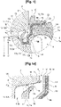
Fig. 1 ] représente partiellement et en coupe longitudinale un palier à roulement équipé d'un dispositif d'étanchéité selon un mode de réalisation de l'invention ; - [
Fig. 1a ] est une vue agrandie de lafigure 1 centrée sur le jeu réduit d'étanchéité formé à l'interface entre le déflecteur et la section extérieure de la paroi d'étanchéité. - En relation avec ces figures, on décrit ci-dessous un palier à roulement, en particulier pour le montage d'une roue motrice ou non motrice d'un véhicule automobile.
- Le palier comprend deux organes, à savoir sur les figures un premier organe 1 disposé extérieurement en étant fixe et un deuxième organe 2 disposé intérieurement en étant tournant. Dans l'application considérée, la roue est destinée à être associée à l'organe intérieur 2 et l'organe extérieur 1 peut présenter des moyens de fixation du palier sur un élément de suspension du véhicule automobile.
- Entre ces deux organes 1, 2, un espace de roulement 3 est formé pour permettre la rotation relative desdits organes autour d'un axe. Dans cette description, les termes de positionnement dans l'espace sont pris en référence à l'axe de rotation du palier (horizontal sur les figures). En particulier :
- le terme « intérieur » est relatif à une disposition proche de cet axe et le terme « extérieur » est relatif à une disposition à distance de cet axe ;
- les termes « axial » et « radial » sont relatifs à une direction respectivement suivant cet axe et s'éloignant ou se rapprochant de lui.
- Pour permettre la rotation, chaque organe 1, 2 peut présenter deux pistes de roulement 1a, 2a espacées axialement de sorte à former dans l'espace de roulement 3 deux chemins de roulement dans lesquels sont disposées respectivement une rangée de corps roulants 4, lesdits corps roulants se présentant par exemple sous la forme de billes qui sont maintenues dans une rangée par l'intermédiaire d'une cage de rétention 5.
- Toutefois, l'invention n'est pas limitée à un mode de réalisation du palier, en particulier relativement à la géométrie des corps roulants 4, à la géométrie et/ou à la disposition relative des organes fixe et tournant.
- Les figures représentent un côté de l'espace de roulement 3 qui présente une chambre annulaire 6 en communication avec l'extérieur par l'intermédiaire d'une ouverture annulaire 7 formée entre les organes 1, 2.
- Dans ce mode de réalisation, le premier organe 1 présente une extension 8 délimitant l'ouverture 7 avec une paroi extérieure 9 du deuxième organe 2, ladite extension étant sous la forme d'un anneau de section sensiblement rectangulaire délimitée par une paroi radiale d'extrémité 8a, une paroi axiale extérieure 8b et une paroi intérieure 8c s'étendant principalement dans la direction axiale et sur laquelle est formée une partie de la piste de roulement 1a.
- Pour empêcher d'une part les fuites de lubrifiant présent dans l'espace de roulement 3 et d'autre part la contamination dudit espace avec des polluants extérieurs, notamment à base de boues, la chambre 6 est équipée d'un dispositif d'étanchéité.
- Le dispositif d'étanchéité comprend :
- une armature 10 solidaire d'un premier organe 1, et pourvue d'un élément d'étanchéité dynamique 11 comprenant au moins une lèvre 11a, 11b disposée dans la chambre 6 ;
- une paroi 12 solidaire du deuxième organe 2 s'étendant dans la chambre 6, et contre laquelle la lèvre 11a, 11b est en contact frottant.
- L'armature 10 peut être réalisée en matériau métallique, notamment par pliage d'une tôle emboutie.
- Sur les figures, la paroi 12 est formée dans le deuxième organe 2. En variante, la paroi 12 peut être formée sur une pièce rapportée sur le deuxième organe 2, ladite pièce pouvant en outre présenter une structure similaire à l'armature 10, notamment en étant formée par pliage d'une tôle emboutie.
- L'armature 10 présente un secteur aval 10a portant l'élément d'étanchéité 11, ledit secteur étant disposé dans la chambre 6 en formant de part et d'autre un compartiment interne 6a et un compartiment externe 6b.
- Dans la description, les termes « amont » et « aval » sont définis par rapport au sens d'introduction des polluants dans l'ouverture 7, depuis l'extérieur vers l'intérieur. Par ailleurs, les termes « externe » et « interne » sont définis par rapport à l'orientation du palier tel que représenté, et se réfèrent à une disposition respectivement à gauche et à droite sur les figures.
- Dans le mode de réalisation représenté, l'étanchéité dynamique est améliorée en prévoyant que l'élément d'étanchéité 11 présente deux lèvres 11a, 11b disposées dans le compartiment externe 6b et en contact frottant en deux endroits espacés de la paroi 12. En variante, au moins une lèvre 11a, 11b peut former un jeu d'étanchéité avec la paroi 12.
- Dans le mode de réalisation représenté, la paroi 12 présente :
- une section radiale 12a, sur laquelle une lèvre extérieure 11a est en contact frottant, afin de former obstacle à la pénétration de polluants extérieurs dans l'espace de roulement 3 ; et
- une section axiale 12b disposée dans le prolongement de la piste de roulement 2a, notamment en s'étendant entre ladite piste de roulement et la section radiale 12a, et sur laquelle une lèvre intérieure 11b est en contact frottant, afin de former obstacle à la fuite de lubrifiants hors dudit espace de roulement.
- Le secteur aval 10a présente une géométrie en U formée d'un fond 13a sensiblement axial bordé par deux parois - respectivement interne 13b et externe 13c - présentant chacune une hauteur radiale, la paroi externe 13c étant prolongée par un déflecteur 11c de l'élément d'étanchéité 11 qui s'étend dans la chambre 6 en séparant avec la géométrie en U les compartiments interne 6a et externe 6b.
- La géométrie en U permet de former dans le compartiment interne 6a une zone de récupération des polluants extérieurs entrant par l'ouverture 7, la longueur du fond 13a et/ou la hauteur des parois radiales 13b, 13c étant suffisamment importante(s) pour contenir lesdits polluants dans ladite zone, et ainsi limiter leur pénétration dans le compartiment externe 6b.
- Pour améliorer à la fois l'étanchéité dynamique et la compacité radiale du palier, la lèvre extérieure 11a présente une extrémité extérieure 25 en contact frottant sur la section radiale 12a en étant disposée suivant un diamètre D qui est supérieur au diamètre D' du fond 13a de la géométrie en U.
- Pour limiter l'entrée de polluants extérieurs dans le compartiment externe 6b, la paroi 12 présente une section extérieure 12c reliée à la section radiale 12a par un congé de raccordement 18, ladite section extérieure bordant la chambre 6 sur une profondeur axiale depuis l'ouverture 7 en formant avec le déflecteur 11c un jeu réduit 14 d'étanchéité entre ladite ouverture et ledit compartiment externe.
- Le déflecteur 11c présente une extrémité libre 15 qui est disposée en regard radial de la section extérieure 12c, le jeu d'étanchéité 14 étant formé entre ladite extrémité libre et ladite section extérieure.
- En particulier, la section extérieure 12c et l'ouverture 7 présentent un bord commun 16 par rapport auquel l'extrémité libre 15 est en retrait axial, ce qui permet d'éviter que des polluants extérieurs venant de l'ouverture 7 ne coulent directement sur le déflecteur 11c, et ainsi de limiter les risques d'entrée desdits polluants dans le compartiment externe 6b.
- En relation avec la
figure 1a , le déflecteur 11c présente une face externe 17a qui est disposée dans le compartiment externe 6b en étant inclinée vers l'ouverture 7 d'un angle β compris entre 10° et 80°, notamment entre 40° et 60°, par rapport à une direction radiale. - Ainsi, la face externe 17a forme une pente pour guider vers l'extérieur d'éventuels polluants contenus dans le compartiment externe 6b, ce qui permet de faciliter l'évacuation par centrifugation et/ou gravité desdits polluants hors dudit compartiment externe.
- Pour améliorer le guidage des polluants hors du compartiment externe 6b, la section extérieure 12c est inclinée extérieurement d'un angle α inférieur à 30° par rapport à une direction axiale.
- De façon avantageuse, l'angle d'inclinaison β de la face externe 17a et l'angle d'inclinaison α de la section extérieure 12c sont tels que : β = - α/2 + θ, θ étant un angle positif supérieur à a/2 et inférieur à 80° de sorte que β soit supérieur à α. En particulier, l'angle θ peut être de l'ordre de 45°.
- Sur les figures, l'élément d'étanchéité 11 présente une couronne 11d disposée dans le prolongement radial de la paroi externe 13c, le déflecteur 11c s'étendant depuis ladite couronne.
- En particulier, la couronne 11d présente une épaisseur supérieure à celle du déflecteur 11c de sorte à pouvoir disposer ledit déflecteur au plus près de la section extérieure 12c, et donc de réduire les dimensions du jeu d'étanchéité 14, tout en limitant la hauteur radiale dudit déflecteur, afin de limiter son fléchissement lorsque des polluants s'écoulent sur lui
- Pour fiabiliser l'absence de transfert de polluants depuis le compartiment interne 6a vers le compartiment externe 6b, le déflecteur 11c présente une face interne 17b disposée dans ledit compartiment interne en entourant le fond 13a de la géométrie en U.
- En particulier, la face interne 17b est inclinée vers l'ouverture d'un angle γ compris entre 40° et 60° par rapport à une direction radiale, ce qui permet de guider vers l'ouverture 7 d'éventuels polluants contenus dans le compartiment interne 6a.
- Dans le mode de réalisation représenté, l'angle α est mesuré par rapport à une direction axiale dans le sens trigonométrique, les angles β et γ étant mesurés dans le sens anti-trigonométrique par rapport à une direction radiale. En particulier, les faces externe 17a et interne 17b sont inclinées vers l'ouverture 7 par rapport à la direction radiale de respectivement une face de la couronne 11d.
- En relation avec la
figure 1a , l'angle γ de la face interne 17b est inférieur à l'angle β de la face externe 17a afin de former un déflecteur de géométrie conique qui s'effile depuis la couronne 11c vers son extrémité libre 15. - De façon avantageuse, la face interne 17b est disposée sensiblement dans l'alignement du bord commun 16 entre l'ouverture 7 et la section extérieure 12c, ce qui permet de guider les polluants depuis ladite face interne directement vers ladite ouverture. En particulier, le bord commun 16 présente un chanfrein d'angle δ sensiblement égal à l'angle γ de la face interne 17b.
- Dans le mode de réalisation représenté, l'armature 10 présente un secteur amont 10b d'association à l'organe extérieur 1, ledit secteur amont présentant une paroi radiale 19a prolongée :
- en son extrémité intérieure par une paroi conique 19b reliant ladite paroi radiale à la paroi interne 13b du secteur aval 10a, et ;
- en son extrémité extérieure, par une paroi extérieure 19c sensiblement axiale ;
- De façon avantageuse, la géométrie conique de la paroi 19b de liaison des secteurs amont 10b et aval 10a permet d'écarter axialement ledit secteur aval de l'espace de roulement, mais également de disposer l'extrémité libre 15 du déflecteur 11c en retrait axial de l'ouverture 7, avec les avantages mentionnés précédemment.
- Sur les figures, l'ouverture 7 est formée au moins partiellement entre le secteur amont 10b et le deuxième organe 2. En particulier, pour limiter la pénétration de polluants extérieurs dans l'ouverture 7, le secteur amont 10b porte :
- un déflecteur 20 sensiblement radial qui est interposé entre l'extérieur et la partie amont de l'ouverture 7, afin de former un chicane contre l'entrée de polluants extérieurs dans ladite partie amont ; et
- un voile d'étanchéité 21 disposé sur la paroi radiale 19a et en regard axial de la portion intérieure de la paroi 9, pouvant former avec ladite portion intérieure une ouverture 7 de dimension axiale réduite.
- En outre, le secteur extérieur 10b présente un bourrelet 22 qui est disposé en appui sur l'excroissance 8 pour former étanchéité statique. En particulier, la paroi extérieure 19c présentant un bord libre 23 décalé radialement afin de permettre un contact entre le bourrelet 22 et la paroi axiale extérieure 8b qui soit garant de l'étanchéité statique.
- L'élément d'étanchéité 11 peut être associé par surmoulage à l'armature 10. En particulier, L'élément d'étanchéité peut être réalisé en matériau souple, par exemple en élastomère, notamment à base de copolymère butadiène nitrile (NBR), éventuellement renforcé mécaniquement par des charges telles que du noir de carbone, de NBR hydrogéné (HNBR), de fluoropolymère ou de polyacrylate.
Claims (15)
- Palier à roulement comprenant deux organes (1, 2) et des corps roulants (4) disposés dans un espace de roulement (3) formé entre lesdits organes pour permettre leur rotation relative autour d'un axe, au moins un côté de l'espace de roulement présentant une chambre annulaire (6) en communication avec l'extérieur par une ouverture (7), ledit palier étant équipé d'un dispositif d'étanchéité comprenant :- une armature (10) solidaire d'un premier organe (1), ladite armature présentant un secteur aval (10a) disposé dans la chambre (6) en formant de part et d'autre un compartiment interne (6a) et un compartiment externe (6b), ledit secteur aval portant un élément d'étanchéité (11) et présentant une géométrie en U formée d'un fond (13a) sensiblement axial bordé par deux parois - respectivement interne (13b) et externe (13c) - présentant chacune une hauteur radiale, ladite paroi externe étant prolongée par un déflecteur (11c) de l'élément d'étanchéité (11) qui s'étend dans ladite chambre en séparant avec la géométrie en U les compartiments interne (6a) et externe (6b) ;- une paroi (12) solidaire du deuxième organe (2), ladite paroi présentant une section extérieure (12c) qui borde la chambre (6) sur une profondeur axiale depuis l'ouverture (7) en formant avec le déflecteur (11c) un jeu réduit d'étanchéité (14) entre l'ouverture (7) et le compartiment externe (6b),le déflecteur (11c) présentant une face externe (17a) disposée dans le compartiment externe (6b), ladite face externe étant inclinée vers l'ouverture (7) d'un angle β compris entre 10° et 80° par rapport à une direction radiale, ledit palier étant caractérisé en ce que le déflecteur (11c) présente une extrémité libre (15) qui est disposée en regard radial de la section extérieure (12c).
- Palier à roulement selon la revendication 1, caractérisé en ce que l'angle β est compris entre 40° et 60°.
- Palier à roulement selon l'une des revendications 1 ou 2, caractérisé en ce que le déflecteur (11c) présente une face interne (17b) disposée dans le compartiment interne (6a), ladite face interne entourant le fond (13a) de la géométrie en U.
- Palier à roulement selon la revendication 3, caractérisé en ce que la face interne (17b) est inclinée vers l'ouverture (7) d'un angle γ compris entre 40° et 60° par rapport à une direction radiale.
- Palier à roulement selon la revendication 4, caractérisé en ce que l'angle γ de la face interne (17b) est inférieur à l'angle β de la face externe (17a).
- Palier à roulement selon l'une des revendications 4 ou 5, caractérisé en ce que la section extérieure (12c) présente un bord commun (16) avec l'ouverture (7), la face interne (17b) étant disposée sensiblement dans l'alignement dudit bord.
- Palier à roulement selon l'une quelconque des revendications 1 à 6, caractérisé en ce que la section extérieure (12c) est inclinée extérieurement d'un angle α inférieur à 30° par rapport à une direction axiale.
- Palier à roulement selon la revendication 7, caractérisé en ce que l'angle d'inclinaison β de la face externe (17a) et l'angle d'inclinaison α de la section extérieure (12c) sont tels que : β = - a/2 + θ, θ étant un angle positif supérieur à a/2 et inférieur à 80° de sorte que β soit supérieur à α.
- Palier à roulement selon l'une quelconque des revendications 1 à 8, caractérisé en ce que l'élément d'étanchéité (11) présente une lèvre (11a) disposée dans le compartiment externe (6b).
- Palier à roulement selon la revendication 9, caractérisé en ce que la lèvre (11a) présente une extrémité extérieure (25) en contact frottant sur la section radiale (12a), ladite extrémité extérieure étant disposée suivant un diamètre D qui est supérieure au diamètre D' du fond (13a) de la géométrie en U.
- Palier à roulement selon l'une quelconque des revendications 1 à 10, caractérisé en ce que la paroi (12) présente une section axiale (12b) disposée dans le prolongement d'une piste de roulement (2a) du deuxième organe (2), l'élément d'étanchéité (11) présentant une lèvre (11b) disposée dans le compartiment externe (6b).
- Palier à roulement selon l'une quelconque des revendications 1 à 11, caractérisé en ce que la paroi (12) est formée dans le deuxième organe (2).
- Palier à roulement selon l'une quelconque des revendications 1 à 12, caractérisé en ce que l'élément d'étanchéité (11) présente une couronne (11d) disposée dans le prolongement radial de la paroi externe (13c), le déflecteur (11c) s'étendant depuis ladite couronne.
- Palier à roulement selon l'une quelconque des revendications 1 à 13, caractérisé en ce que l'armature (10) présente un secteur amont (10b) d'association au premier organe (1).
- Palier à roulement selon la revendication 14, caractérisé en ce que le secteur amont (10b) porte un déflecteur (20) qui est interposé entre l'extérieur et la partie amont de l'ouverture (7).
Applications Claiming Priority (1)
| Application Number | Priority Date | Filing Date | Title |
|---|---|---|---|
| FR1900273A FR3091733B1 (fr) | 2019-01-11 | 2019-01-11 | Palier à roulement équipé d’un dispositif d’étanchéité |
Publications (2)
| Publication Number | Publication Date |
|---|---|
| EP3680500A1 EP3680500A1 (fr) | 2020-07-15 |
| EP3680500B1 true EP3680500B1 (fr) | 2022-06-15 |
Family
ID=66676814
Family Applications (1)
| Application Number | Title | Priority Date | Filing Date |
|---|---|---|---|
| EP20150600.3A Active EP3680500B1 (fr) | 2019-01-11 | 2020-01-07 | Palier à roulement équipé d'un dispositif d étanchéité |
Country Status (4)
| Country | Link |
|---|---|
| US (1) | US10982718B2 (fr) |
| EP (1) | EP3680500B1 (fr) |
| CN (1) | CN111434936B (fr) |
| FR (1) | FR3091733B1 (fr) |
Families Citing this family (1)
| Publication number | Priority date | Publication date | Assignee | Title |
|---|---|---|---|---|
| DE102022001488A1 (de) | 2022-04-28 | 2023-11-02 | C&U Europe Holding GmbH | Außenlagerteil für eine Wälzlagervorrichtung, Wälzlagervorrichtung für eine Radanordnung eines Fahrzeugs mit dem Außenlagerteil und Radanordnung mit der Wälzlagervorrichtung. |
Family Cites Families (16)
| Publication number | Priority date | Publication date | Assignee | Title |
|---|---|---|---|---|
| KR100799643B1 (ko) * | 2006-08-09 | 2008-01-30 | 주식회사 일진글로벌 | 감도가 개선된 인코더 일체형 시일 |
| DE102008017409B4 (de) * | 2008-04-05 | 2016-02-11 | Schaeffler Technologies AG & Co. KG | Dichtungsanordnung sowie Radlager mit der Dichtungsanordnung |
| FR2971570B1 (fr) * | 2011-02-11 | 2013-04-19 | Ntn Snr Roulements | Palier a roulement presentant une extension annulaire et un dispositif d'etancheite |
| CN202811822U (zh) * | 2012-06-29 | 2013-03-20 | 岛野股份有限公司 | 用于自行车的转动轴承 |
| DE102013217299B4 (de) * | 2013-08-30 | 2018-09-13 | Schaeffler Technologies AG & Co. KG | Dichtungsanordnung mit einem Schleuderring für ein Wälzlager |
| JP2015052350A (ja) * | 2013-09-06 | 2015-03-19 | 内山工業株式会社 | 軸受密封装置 |
| DE102013218635B4 (de) * | 2013-09-17 | 2015-09-24 | Schaeffler Technologies AG & Co. KG | Dichtungsanordnung für Radlager mit vorgespanntem Schleuderblech |
| ITTO20130980A1 (it) * | 2013-11-29 | 2015-05-30 | Skf Ab | Complesso di tenuta a basso attrito, sistema di accoppiamento con un anello di cuscinetto ed unita¿ mozzo ruota equipaggiata con tale complesso di tenuta |
| JP6519165B2 (ja) * | 2014-10-30 | 2019-05-29 | 日本精工株式会社 | 転がり軸受用密封装置、及び密封形転がり軸受 |
| FR3033852B1 (fr) * | 2015-03-19 | 2017-03-24 | Ntn-Snr Roulements | Palier a roulement equipe d'un dispositif d'etancheite comprenant deux armatures |
| ITUB20151194A1 (it) * | 2015-05-29 | 2016-11-29 | Skf Ab | Cuscinetto di rotolamento includente un dispositivo di tenuta a basso attrito, in particolare per un gruppo mozzo ruota. |
| JP6603078B2 (ja) * | 2015-08-31 | 2019-11-06 | Ntn株式会社 | 車輪用軸受装置 |
| FR3042005B1 (fr) * | 2015-10-01 | 2018-04-20 | Ntn-Snr Roulements | Palier a roulement |
| ITUA20162310A1 (it) * | 2016-04-05 | 2017-10-05 | Skf Ab | Dispositivo di tenuta a basso attrito e cuscinetto di rotolamento dotato dello stesso. |
| DE102017108386A1 (de) | 2017-04-20 | 2018-10-25 | Schaeffler Technologies AG & Co. KG | Dichtungsanordnung eines Radlagers |
| DE102018105832A1 (de) * | 2018-03-14 | 2019-09-19 | Schaeffler Technologies AG & Co. KG | Kassettendichtung mit Doppellabyrinth und Fliehkraftdichtung |
-
2019
- 2019-01-11 FR FR1900273A patent/FR3091733B1/fr active Active
-
2020
- 2020-01-06 US US16/734,493 patent/US10982718B2/en not_active Expired - Fee Related
- 2020-01-07 EP EP20150600.3A patent/EP3680500B1/fr active Active
- 2020-01-10 CN CN202010024093.7A patent/CN111434936B/zh active Active
Also Published As
| Publication number | Publication date |
|---|---|
| CN111434936B (zh) | 2023-10-10 |
| EP3680500A1 (fr) | 2020-07-15 |
| FR3091733A1 (fr) | 2020-07-17 |
| US20200224723A1 (en) | 2020-07-16 |
| US10982718B2 (en) | 2021-04-20 |
| FR3091733B1 (fr) | 2021-02-12 |
| CN111434936A (zh) | 2020-07-21 |
Similar Documents
| Publication | Publication Date | Title |
|---|---|---|
| FR3075103B1 (fr) | Dispositif de butee de suspension et jambe de force equipee d’un tel dispositif | |
| WO2012107693A1 (fr) | Palier a roulement presentant une extension annulaire et un dispositif d'etancheite | |
| FR3074861A1 (fr) | Palier a roulement equipe d'un dispositif d'etancheite | |
| EP3626486A1 (fr) | Butée de suspension de véhicule automobile | |
| EP1846665A1 (fr) | Palier a roulement conique comprenant une cage de filtration | |
| EP1277978A1 (fr) | Palier à corps roulants coniques pourvu d'un dispostif d'étanchéité | |
| FR3018321A1 (fr) | Palier a roulement equipe d’un dispositif d’etancheite comprenant une armature | |
| EP3680500A1 (fr) | Palier à roulement équipé d'un dispositif d étanchéité | |
| EP2821662B1 (fr) | Ensemble de roulement et moyeu de roue pour véhicule motorisé avec dispositif d'étanchéité | |
| FR2971825A1 (fr) | Palier a roulement, notamment pour dispositif de butee de debrayage. | |
| EP3299649B1 (fr) | Palier à roulement équipé d'un dispositif d'étanchéité | |
| WO2017055724A1 (fr) | Palier à roulement | |
| EP3015728B1 (fr) | Palier à roulement équipé d'un dispositif d étanchéité comprenant une armature | |
| FR3114850A1 (fr) | Dispositif d’étanchéité pour palier à roulement | |
| FR3064705B1 (fr) | Palier a roulement | |
| FR3079585A1 (fr) | Dispositif de poulie pour galet tendeur ou enrouleur | |
| FR3018874A1 (fr) | Palier a roulement equipe d’un dispositif d’etancheite comprenant une armature | |
| EP2299129B1 (fr) | Palier à roulement à étanchéité ameliorée | |
| FR3120668A1 (fr) | Dispositif d’étanchéité pour palier comprenant un passage amont équipé d’une gouttière | |
| FR3116091A1 (fr) | Palier à roulement | |
| FR3109416A1 (fr) | Dispositif d’étanchéité pour un palier à roulement | |
| FR3109615A1 (fr) | Dispositif d’étanchéité pour un palier à roulement | |
| FR3033851A1 (fr) | Palier a roulement equipe d'un dispositif d'etancheite comprenant une armature | |
| FR3143693A1 (fr) | Palier à roulement équipé d’un dispositif d’étanchéité | |
| FR3018320A1 (fr) | Palier a roulement comprenant un dispositif d’etancheite |
Legal Events
| Date | Code | Title | Description |
|---|---|---|---|
| PUAI | Public reference made under article 153(3) epc to a published international application that has entered the european phase |
Free format text: ORIGINAL CODE: 0009012 |
|
| STAA | Information on the status of an ep patent application or granted ep patent |
Free format text: STATUS: THE APPLICATION HAS BEEN PUBLISHED |
|
| AK | Designated contracting states |
Kind code of ref document: A1 Designated state(s): AL AT BE BG CH CY CZ DE DK EE ES FI FR GB GR HR HU IE IS IT LI LT LU LV MC MK MT NL NO PL PT RO RS SE SI SK SM TR |
|
| AX | Request for extension of the european patent |
Extension state: BA ME |
|
| STAA | Information on the status of an ep patent application or granted ep patent |
Free format text: STATUS: REQUEST FOR EXAMINATION WAS MADE |
|
| 17P | Request for examination filed |
Effective date: 20210114 |
|
| RBV | Designated contracting states (corrected) |
Designated state(s): AL AT BE BG CH CY CZ DE DK EE ES FI FR GB GR HR HU IE IS IT LI LT LU LV MC MK MT NL NO PL PT RO RS SE SI SK SM TR |
|
| GRAP | Despatch of communication of intention to grant a patent |
Free format text: ORIGINAL CODE: EPIDOSNIGR1 |
|
| STAA | Information on the status of an ep patent application or granted ep patent |
Free format text: STATUS: GRANT OF PATENT IS INTENDED |
|
| INTG | Intention to grant announced |
Effective date: 20220103 |
|
| GRAS | Grant fee paid |
Free format text: ORIGINAL CODE: EPIDOSNIGR3 |
|
| GRAA | (expected) grant |
Free format text: ORIGINAL CODE: 0009210 |
|
| STAA | Information on the status of an ep patent application or granted ep patent |
Free format text: STATUS: THE PATENT HAS BEEN GRANTED |
|
| AK | Designated contracting states |
Kind code of ref document: B1 Designated state(s): AL AT BE BG CH CY CZ DE DK EE ES FI FR GB GR HR HU IE IS IT LI LT LU LV MC MK MT NL NO PL PT RO RS SE SI SK SM TR |
|
| REG | Reference to a national code |
Ref country code: CH Ref legal event code: EP Ref country code: GB Ref legal event code: FG4D Free format text: NOT ENGLISH |
|
| REG | Reference to a national code |
Ref country code: IE Ref legal event code: FG4D Free format text: LANGUAGE OF EP DOCUMENT: FRENCH |
|
| REG | Reference to a national code |
Ref country code: DE Ref legal event code: R096 Ref document number: 602020003499 Country of ref document: DE |
|
| REG | Reference to a national code |
Ref country code: AT Ref legal event code: REF Ref document number: 1498561 Country of ref document: AT Kind code of ref document: T Effective date: 20220715 |
|
| REG | Reference to a national code |
Ref country code: LT Ref legal event code: MG9D |
|
| REG | Reference to a national code |
Ref country code: NL Ref legal event code: MP Effective date: 20220615 |
|
| PG25 | Lapsed in a contracting state [announced via postgrant information from national office to epo] |
Ref country code: SE Free format text: LAPSE BECAUSE OF FAILURE TO SUBMIT A TRANSLATION OF THE DESCRIPTION OR TO PAY THE FEE WITHIN THE PRESCRIBED TIME-LIMIT Effective date: 20220615 Ref country code: NO Free format text: LAPSE BECAUSE OF FAILURE TO SUBMIT A TRANSLATION OF THE DESCRIPTION OR TO PAY THE FEE WITHIN THE PRESCRIBED TIME-LIMIT Effective date: 20220915 Ref country code: LT Free format text: LAPSE BECAUSE OF FAILURE TO SUBMIT A TRANSLATION OF THE DESCRIPTION OR TO PAY THE FEE WITHIN THE PRESCRIBED TIME-LIMIT Effective date: 20220615 Ref country code: HR Free format text: LAPSE BECAUSE OF FAILURE TO SUBMIT A TRANSLATION OF THE DESCRIPTION OR TO PAY THE FEE WITHIN THE PRESCRIBED TIME-LIMIT Effective date: 20220615 Ref country code: GR Free format text: LAPSE BECAUSE OF FAILURE TO SUBMIT A TRANSLATION OF THE DESCRIPTION OR TO PAY THE FEE WITHIN THE PRESCRIBED TIME-LIMIT Effective date: 20220916 Ref country code: FI Free format text: LAPSE BECAUSE OF FAILURE TO SUBMIT A TRANSLATION OF THE DESCRIPTION OR TO PAY THE FEE WITHIN THE PRESCRIBED TIME-LIMIT Effective date: 20220615 Ref country code: BG Free format text: LAPSE BECAUSE OF FAILURE TO SUBMIT A TRANSLATION OF THE DESCRIPTION OR TO PAY THE FEE WITHIN THE PRESCRIBED TIME-LIMIT Effective date: 20220915 |
|
| REG | Reference to a national code |
Ref country code: AT Ref legal event code: MK05 Ref document number: 1498561 Country of ref document: AT Kind code of ref document: T Effective date: 20220615 |
|
| PG25 | Lapsed in a contracting state [announced via postgrant information from national office to epo] |
Ref country code: RS Free format text: LAPSE BECAUSE OF FAILURE TO SUBMIT A TRANSLATION OF THE DESCRIPTION OR TO PAY THE FEE WITHIN THE PRESCRIBED TIME-LIMIT Effective date: 20220615 Ref country code: LV Free format text: LAPSE BECAUSE OF FAILURE TO SUBMIT A TRANSLATION OF THE DESCRIPTION OR TO PAY THE FEE WITHIN THE PRESCRIBED TIME-LIMIT Effective date: 20220615 |
|
| PG25 | Lapsed in a contracting state [announced via postgrant information from national office to epo] |
Ref country code: NL Free format text: LAPSE BECAUSE OF FAILURE TO SUBMIT A TRANSLATION OF THE DESCRIPTION OR TO PAY THE FEE WITHIN THE PRESCRIBED TIME-LIMIT Effective date: 20220615 |
|
| PG25 | Lapsed in a contracting state [announced via postgrant information from national office to epo] |
Ref country code: SM Free format text: LAPSE BECAUSE OF FAILURE TO SUBMIT A TRANSLATION OF THE DESCRIPTION OR TO PAY THE FEE WITHIN THE PRESCRIBED TIME-LIMIT Effective date: 20220615 Ref country code: SK Free format text: LAPSE BECAUSE OF FAILURE TO SUBMIT A TRANSLATION OF THE DESCRIPTION OR TO PAY THE FEE WITHIN THE PRESCRIBED TIME-LIMIT Effective date: 20220615 Ref country code: RO Free format text: LAPSE BECAUSE OF FAILURE TO SUBMIT A TRANSLATION OF THE DESCRIPTION OR TO PAY THE FEE WITHIN THE PRESCRIBED TIME-LIMIT Effective date: 20220615 Ref country code: PT Free format text: LAPSE BECAUSE OF FAILURE TO SUBMIT A TRANSLATION OF THE DESCRIPTION OR TO PAY THE FEE WITHIN THE PRESCRIBED TIME-LIMIT Effective date: 20221017 Ref country code: ES Free format text: LAPSE BECAUSE OF FAILURE TO SUBMIT A TRANSLATION OF THE DESCRIPTION OR TO PAY THE FEE WITHIN THE PRESCRIBED TIME-LIMIT Effective date: 20220615 Ref country code: EE Free format text: LAPSE BECAUSE OF FAILURE TO SUBMIT A TRANSLATION OF THE DESCRIPTION OR TO PAY THE FEE WITHIN THE PRESCRIBED TIME-LIMIT Effective date: 20220615 Ref country code: CZ Free format text: LAPSE BECAUSE OF FAILURE TO SUBMIT A TRANSLATION OF THE DESCRIPTION OR TO PAY THE FEE WITHIN THE PRESCRIBED TIME-LIMIT Effective date: 20220615 Ref country code: AT Free format text: LAPSE BECAUSE OF FAILURE TO SUBMIT A TRANSLATION OF THE DESCRIPTION OR TO PAY THE FEE WITHIN THE PRESCRIBED TIME-LIMIT Effective date: 20220615 |
|
| PG25 | Lapsed in a contracting state [announced via postgrant information from national office to epo] |
Ref country code: PL Free format text: LAPSE BECAUSE OF FAILURE TO SUBMIT A TRANSLATION OF THE DESCRIPTION OR TO PAY THE FEE WITHIN THE PRESCRIBED TIME-LIMIT Effective date: 20220615 Ref country code: IS Free format text: LAPSE BECAUSE OF FAILURE TO SUBMIT A TRANSLATION OF THE DESCRIPTION OR TO PAY THE FEE WITHIN THE PRESCRIBED TIME-LIMIT Effective date: 20221015 |
|
| REG | Reference to a national code |
Ref country code: DE Ref legal event code: R097 Ref document number: 602020003499 Country of ref document: DE |
|
| PG25 | Lapsed in a contracting state [announced via postgrant information from national office to epo] |
Ref country code: AL Free format text: LAPSE BECAUSE OF FAILURE TO SUBMIT A TRANSLATION OF THE DESCRIPTION OR TO PAY THE FEE WITHIN THE PRESCRIBED TIME-LIMIT Effective date: 20220615 |
|
| PLBE | No opposition filed within time limit |
Free format text: ORIGINAL CODE: 0009261 |
|
| STAA | Information on the status of an ep patent application or granted ep patent |
Free format text: STATUS: NO OPPOSITION FILED WITHIN TIME LIMIT |
|
| PG25 | Lapsed in a contracting state [announced via postgrant information from national office to epo] |
Ref country code: DK Free format text: LAPSE BECAUSE OF FAILURE TO SUBMIT A TRANSLATION OF THE DESCRIPTION OR TO PAY THE FEE WITHIN THE PRESCRIBED TIME-LIMIT Effective date: 20220615 |
|
| 26N | No opposition filed |
Effective date: 20230316 |
|
| PG25 | Lapsed in a contracting state [announced via postgrant information from national office to epo] |
Ref country code: SI Free format text: LAPSE BECAUSE OF FAILURE TO SUBMIT A TRANSLATION OF THE DESCRIPTION OR TO PAY THE FEE WITHIN THE PRESCRIBED TIME-LIMIT Effective date: 20220615 |
|
| REG | Reference to a national code |
Ref country code: CH Ref legal event code: PL |
|
| PG25 | Lapsed in a contracting state [announced via postgrant information from national office to epo] |
Ref country code: LU Free format text: LAPSE BECAUSE OF NON-PAYMENT OF DUE FEES Effective date: 20230107 |
|
| REG | Reference to a national code |
Ref country code: BE Ref legal event code: MM Effective date: 20230131 |
|
| PG25 | Lapsed in a contracting state [announced via postgrant information from national office to epo] |
Ref country code: LI Free format text: LAPSE BECAUSE OF NON-PAYMENT OF DUE FEES Effective date: 20230131 Ref country code: CH Free format text: LAPSE BECAUSE OF NON-PAYMENT OF DUE FEES Effective date: 20230131 |
|
| PG25 | Lapsed in a contracting state [announced via postgrant information from national office to epo] |
Ref country code: BE Free format text: LAPSE BECAUSE OF NON-PAYMENT OF DUE FEES Effective date: 20230131 |
|
| PG25 | Lapsed in a contracting state [announced via postgrant information from national office to epo] |
Ref country code: IT Free format text: LAPSE BECAUSE OF FAILURE TO SUBMIT A TRANSLATION OF THE DESCRIPTION OR TO PAY THE FEE WITHIN THE PRESCRIBED TIME-LIMIT Effective date: 20220615 Ref country code: IE Free format text: LAPSE BECAUSE OF NON-PAYMENT OF DUE FEES Effective date: 20230107 |
|
| PG25 | Lapsed in a contracting state [announced via postgrant information from national office to epo] |
Ref country code: MC Free format text: LAPSE BECAUSE OF FAILURE TO SUBMIT A TRANSLATION OF THE DESCRIPTION OR TO PAY THE FEE WITHIN THE PRESCRIBED TIME-LIMIT Effective date: 20220615 |
|
| PG25 | Lapsed in a contracting state [announced via postgrant information from national office to epo] |
Ref country code: MC Free format text: LAPSE BECAUSE OF FAILURE TO SUBMIT A TRANSLATION OF THE DESCRIPTION OR TO PAY THE FEE WITHIN THE PRESCRIBED TIME-LIMIT Effective date: 20220615 |
|
| GBPC | Gb: european patent ceased through non-payment of renewal fee |
Effective date: 20240107 |
|
| PG25 | Lapsed in a contracting state [announced via postgrant information from national office to epo] |
Ref country code: GB Free format text: LAPSE BECAUSE OF NON-PAYMENT OF DUE FEES Effective date: 20240107 |
|
| PG25 | Lapsed in a contracting state [announced via postgrant information from national office to epo] |
Ref country code: GB Free format text: LAPSE BECAUSE OF NON-PAYMENT OF DUE FEES Effective date: 20240107 |
|
| PG25 | Lapsed in a contracting state [announced via postgrant information from national office to epo] |
Ref country code: BG Free format text: LAPSE BECAUSE OF FAILURE TO SUBMIT A TRANSLATION OF THE DESCRIPTION OR TO PAY THE FEE WITHIN THE PRESCRIBED TIME-LIMIT Effective date: 20220615 |
|
| PG25 | Lapsed in a contracting state [announced via postgrant information from national office to epo] |
Ref country code: BG Free format text: LAPSE BECAUSE OF FAILURE TO SUBMIT A TRANSLATION OF THE DESCRIPTION OR TO PAY THE FEE WITHIN THE PRESCRIBED TIME-LIMIT Effective date: 20220615 |
|
| PGFP | Annual fee paid to national office [announced via postgrant information from national office to epo] |
Ref country code: DE Payment date: 20250121 Year of fee payment: 6 |
|
| PG25 | Lapsed in a contracting state [announced via postgrant information from national office to epo] |
Ref country code: CY Free format text: LAPSE BECAUSE OF FAILURE TO SUBMIT A TRANSLATION OF THE DESCRIPTION OR TO PAY THE FEE WITHIN THE PRESCRIBED TIME-LIMIT; INVALID AB INITIO Effective date: 20200107 |
|
| PG25 | Lapsed in a contracting state [announced via postgrant information from national office to epo] |
Ref country code: HU Free format text: LAPSE BECAUSE OF FAILURE TO SUBMIT A TRANSLATION OF THE DESCRIPTION OR TO PAY THE FEE WITHIN THE PRESCRIBED TIME-LIMIT; INVALID AB INITIO Effective date: 20200107 |
|
| PG25 | Lapsed in a contracting state [announced via postgrant information from national office to epo] |
Ref country code: TR Free format text: LAPSE BECAUSE OF FAILURE TO SUBMIT A TRANSLATION OF THE DESCRIPTION OR TO PAY THE FEE WITHIN THE PRESCRIBED TIME-LIMIT Effective date: 20220615 |
|
| PGFP | Annual fee paid to national office [announced via postgrant information from national office to epo] |
Ref country code: FR Payment date: 20260123 Year of fee payment: 7 |