EP3680392A1 - Aufbau eines riegelträgers und eines kupplungsstücks - Google Patents
Aufbau eines riegelträgers und eines kupplungsstücks Download PDFInfo
- Publication number
- EP3680392A1 EP3680392A1 EP20151592.1A EP20151592A EP3680392A1 EP 3680392 A1 EP3680392 A1 EP 3680392A1 EP 20151592 A EP20151592 A EP 20151592A EP 3680392 A1 EP3680392 A1 EP 3680392A1
- Authority
- EP
- European Patent Office
- Prior art keywords
- waling
- coupling
- waling beam
- beams
- coupling piece
- Prior art date
- Legal status (The legal status is an assumption and is not a legal conclusion. Google has not performed a legal analysis and makes no representation as to the accuracy of the status listed.)
- Withdrawn
Links
- 230000008878 coupling Effects 0.000 title claims abstract description 121
- 238000010168 coupling process Methods 0.000 title claims abstract description 121
- 238000005859 coupling reaction Methods 0.000 title claims abstract description 121
- 239000012530 fluid Substances 0.000 claims description 5
- 238000009412 basement excavation Methods 0.000 description 4
- 238000009434 installation Methods 0.000 description 3
- 238000004519 manufacturing process Methods 0.000 description 3
- 238000000034 method Methods 0.000 description 3
- 239000004576 sand Substances 0.000 description 3
- 238000003466 welding Methods 0.000 description 2
- 229910000831 Steel Inorganic materials 0.000 description 1
- 230000003213 activating effect Effects 0.000 description 1
- 230000007423 decrease Effects 0.000 description 1
- 238000009826 distribution Methods 0.000 description 1
- 238000005553 drilling Methods 0.000 description 1
- 230000000694 effects Effects 0.000 description 1
- 230000012447 hatching Effects 0.000 description 1
- 230000008092 positive effect Effects 0.000 description 1
- 230000000717 retained effect Effects 0.000 description 1
- 239000010959 steel Substances 0.000 description 1
- 230000003313 weakening effect Effects 0.000 description 1
Images





Classifications
-
- E—FIXED CONSTRUCTIONS
- E02—HYDRAULIC ENGINEERING; FOUNDATIONS; SOIL SHIFTING
- E02D—FOUNDATIONS; EXCAVATIONS; EMBANKMENTS; UNDERGROUND OR UNDERWATER STRUCTURES
- E02D17/00—Excavations; Bordering of excavations; Making embankments
- E02D17/02—Foundation pits
- E02D17/04—Bordering surfacing or stiffening the sides of foundation pits
-
- E—FIXED CONSTRUCTIONS
- E02—HYDRAULIC ENGINEERING; FOUNDATIONS; SOIL SHIFTING
- E02D—FOUNDATIONS; EXCAVATIONS; EMBANKMENTS; UNDERGROUND OR UNDERWATER STRUCTURES
- E02D17/00—Excavations; Bordering of excavations; Making embankments
- E02D17/06—Foundation trenches ditches or narrow shafts
- E02D17/08—Bordering or stiffening the sides of ditches trenches or narrow shafts for foundations
-
- E—FIXED CONSTRUCTIONS
- E02—HYDRAULIC ENGINEERING; FOUNDATIONS; SOIL SHIFTING
- E02D—FOUNDATIONS; EXCAVATIONS; EMBANKMENTS; UNDERGROUND OR UNDERWATER STRUCTURES
- E02D17/00—Excavations; Bordering of excavations; Making embankments
- E02D17/06—Foundation trenches ditches or narrow shafts
- E02D17/08—Bordering or stiffening the sides of ditches trenches or narrow shafts for foundations
- E02D17/083—Shoring struts
Definitions
- the present invention relates to an assembly of a waling beam for retaining a retaining wall and a coupling piece for coupling the waling beam to another body, wherein at least one outer side of the waling beam is provided with a plurality of coupling elements which are located at a distance from each other in longitudinal direction of the waling beam and the coupling piece is provided with a coupling member which is connectable to each of the coupling elements, wherein the coupling member and each of the coupling elements form a cooperating projection and cavity which fit to each other such that the coupling piece is lockable with respect to the waling beam in at least one of the longitudinal direction and transverse direction of the waling beam.
- Such an assembly is known from KR20120055236 .
- the H-shaped waling beam is provided with a large number of holes in its longitudinal direction for receiving bolts which can be put through holes of the coupling piece which is to be mounted to the waling beam as soon as the holes of the waling beam and the coupling piece face each other.
- the coupling piece constitutes a joint between the waling beam and a strut.
- the holes in de waling beam can be considered as being coupling elements and the group of bolts through the coupling piece and the waling beam can be considered as being a coupling member, through which a coupling of the coupling piece is possible at different locations along the waling beam.
- the bolts lock the coupling piece with respect to the waling beam in horizontal and vertical direction and the group of bolts can be considered as being a coupling member of the coupling piece which coupling member constitutes a projection.
- An object of the invention is to provide an assembly which can be installed in a simple manner.
- the advantage of this feature is that the projection can be inserted directly into a cavity without a need of accurately positioning the waling beam and the coupling piece with respect to each other at first and only after that locking the waling beam and the coupling piece with respect to each other.
- the coupling piece may be used as a press piece between a strut and waling beam of a strut system, for example.
- the assembly according to the invention provides the possibility to position the press piece at different locations along the waling beam, which provides great flexibility for installing a strut system.
- the coupling piece may also be used for a coupling between a diagonal strut and the waling beam.
- the coupling piece which cooperates with the diagonal strut can be placed at a different location along a waling beam in a simple manner.
- the coupling piece may be a shear piece, which can be mounted to the waling beam at a plurality of locations at a side of the waling beam, which side is facing the retaining wall.
- the shear piece may constitute a lock between the waling beam and the retaining wall in the longitudinal direction of the waling beam.
- the retaining wall is a sheet pile wall the shear piece may rest against a section of the sheet pile wall which extends in transverse direction of the waling beam.
- the projection may be unreleasably connected to one of the waling beam and the coupling piece, for example by means of a welding joint.
- the projection and one of the waling beam and the coupling piece are made from one piece, since this improves rigidity.
- the assembly may be provided with a brace for attaching the coupling piece and the waling beam to each other in a direction perpendicular to the at least one outer side of the waling beam, wherein in the assembled condition the brace is engaged about at least a part of the waling beam.
- a brace for attaching the coupling piece and the waling beam to each other in a direction perpendicular to the at least one outer side of the waling beam, wherein in the assembled condition the brace is engaged about at least a part of the waling beam.
- the coupling member of the coupling piece forms the projection and the at least one outer side of the waling beam is provided with a series of pair of notches located at a distance from each other in longitudinal direction of the waling beam, wherein each of the pairs of notches comprises two notches which are located at a distance from each other in transverse direction of the waling beam, wherein common spaces between two neigbbouring pairs of notches and between the notches of each of these pairs of notches form the coupling elements in the form of a series of cavities for receiving the coupling member of the coupling piece at different locations along the waling beam.
- the waling beam comprises an H-shaped beam profile including a web between two parallel plates, wherein the projection and the cavity are located at least partially at the location of the web.
- the projection can exert a force at the location of the web of the wailing beam, which has a positive effect on the force distribution on the waling beam.
- the space between the notches of each of the pairs of notches may be located at the height level of the web.
- the notches may be applied mirror symmetrically with respect to the web.
- the assembly may be provided with an additional waling beam, wherein in the assembled condition both waling beams are located above each other for supporting a retaining wall together and wherein the assembly is provided with two independent push bars for exerting respective pushing forces on the respective waling beams in transverse direction of the waling beams.
- the independent push bars provide the possibility of applying a prestressing force onto a retaining wall by both waling beams without affecting the position of one push bar by the position of the other push bar. This may be realised, for example, by applying a jack next to each push bar, for example a hydraulic cylinder, after which the push bars may keep the resulting positions of the respective waling beams and the jacks can be removed.
- the assembly may be provided with an additional coupling piece wherein the push bars are connected to the respective waling beams through both coupling pieces.
- the push bars are part of a strut member for supporting a plurality of waling beams located above each other for retaining a retaining wall, wherein the strut member is also provided with a frame, which comprises two guides for guiding the respective push bars, wherein the push bars are extendable through the respective guides in the same direction with respect to the frame, and a locking system for locking the push bars in a certain extended condition with respect to the frame.
- the strut member may be part of a strut of a strut system, for example.
- the strut member has three guides including three extendable push bars, of which the centrelines lie in one plane and the distance between two neighbouring push bars is equal.
- the inner one of the three guides is directly connected to both outer guides and the outer guides are directly connected to each other through curved plates. This provides a large area moment of inertia.
- each guide comprises a cylinder, which is closed at one side by the cooperating push bar and which is closed at the opposite side by a closure which is fixed to the frame, wherein the cylinder is provided with a filling hole for filling the cylinder with an incompressible fluid so as to form the locking system.
- the cylinder can also be provided with a sealable discharge hole for emptying the cylinder. Preferably, this is located at the lower side of the cylinder such that upon dismounting a strut system the pressure on the push bars can be removed in a simple manner by opening the discharge hole. Then, the fluid can flow away and the push bar can be retracted in the cylinder.
- the assembly may be provided with a press unit which is connectable to the strut member and provided with jacks which are located at either side of each push bar in connected condition and wherein the frame and the press unit are adapted such that in connected condition the jacks can exert a force on the corresponding waling beam by pushing against the frame.
- the press unit provides the possibility to apply a prestressing force on the waling beams which are located above each other at the same time by means of the jacks, to engage the push bars to the waling beams and to fix their positions, after which the press unit of the frame can be removed and used for a next strut member.
- each push bar may engage a connecting piece at the location of the waling beam, to which connecting piece the push bar is attached, as well. This causes the push bar to be extended upon activating the jacks.
- the upper one of both waling beams is supported by the lower one of both waling beams through calibration blocks which are located at the respective webs between the respective parallel plates.
- the parallel plates of the upper waling beam are separate from those of the lower waling beam.
- the calibration blocks keep the webs of the waling beams which are located above each other at a desired mutual distance. Due to manufacturing variations of the waling beams deviations of the dimensions of the plates with respect to the web are possible.
- the webs of the respective waling beams can also be kept on a corresponding fixed distance by means of the calibration blocks.
- the calibration blocks can be applied independently from the above-mentioned coupling elements and coupling pieces.
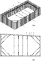
- Figs. 1 and 2 show a building excavation which is bordered in circumferential direction by a sheet pile wall 1.
- the ground around the sheet pile wall 1 is omitted for clarity reasons, such that the outer side of the sheet pile wall 1 is visible.
- Waling beams 2 are applied along the inner side of the sheet pile wall 1, which waling beams 2 are coupled to each other so as to form a strut system along the inner circumference of the sheet pile wall 1.
- the strut system has three series of waling beams 2 which are placed above each other, but a different number is conceivable.
- the waling beams 2 are pushed against the sheet pile wall 1 by struts 3 and diagonal struts 4.
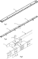
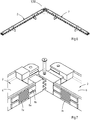
- Fig. 3 shows one of the waling beams 2 and Fig. 4 shows two identical waling beams 2 which are coupled to each other. In the situation as shown the two waling beams 2 are aligned. It can be seen in Fig. 5 that the waling beams 2 are coupled to each other by means of two pins 5 having circular cross-sections.
- Each waling beam 2 has a middle section having an H-shaped beam profile.
- the H-shaped beam profile has a web 6 between two parallel plates 7, which web 6 extends perpendicularly to the parallel plates 7.
- Steel blocks are welded at either side of the H-shaped middle section of each waling beam 2. After welding, the blocks are machined in order to obtain the shape as shown in Fig. 5 .
- Both blocks of each waling beam 2 are provided with coupling plates which extend parallel to the web 6, which coupling plates are dimensioned such that the plates of the one waling beam 2 fit between the coupling plates of the other waling beam 2, as illustrated in Fig. 5 .
- the application of two pins 5 having circular cross-sections and the coupling plates provide an additional advantage, which is illustrated in Figs. 6 and 7 .
- the waling beams 2 provide the possibility to be placed at an angle with respect to each other and to be coupled to each other by means of one pin 5. This leads to a corner coupling of the strut system and a pivoting effect at the same time.
- Each waling beam 2 is also provide with substantially identical pairs of notches which are located at a distance from each other, wherein each pair of notches comprises a lower notch plate 8a and an upper notch plate 8b which are located above each other.
- the pairs of notch plates 8a, 8b are welded against one or both plates 7 of the waling beam 2 at the outer side of the waling beam 2.
- the cavity between the two notch plates 8a, 8b of each pair lies at the height level of the web 6.
- the mutual distance of the pairs of notches in longitudinal direction of the waling beam 2 is equal in the embodiment as shown in the figures.
- the notch plates 8a, 8b cooperate with a coupling piece 9, which is shown in detail in Figs. 8-13 .
- the coupling piece 9 constitutes a press piece between the respective struts 3 and diagonal struts 4, on the one hand, and the waling beam 2, on the other hand, as shown in Figs. 1 and 2 , in order to transmit the force of the strut 3 or the diagonal strut 4 to the waling beam 2 through the corresponding coupling piece 9.
- the coupling piece 9 is provided with a main plate 10 of which an end portion fits in the cavity between the notch plates 8a, 8b of each of the pairs of notches.
- the coupling piece 9 further comprises two lower cross plates 11a and two upper cross plates 11b which extend perpendicularly to the main plate 10 and are welded to it.
- end portions of one or more pairs of the lower and upper cross plate 11a, 11b may abut one or more respective pairs of notch plates 8a, 8b, such that the coupling piece 9 is locked with respect to the waling beam 2 in longitudinal direction of the waling beam 2.
- end portions of the main plate 10 and of the cross plates 11a, 11b constitute the coupling member in the form of a projection of the coupling piece 9.
- This projection fits in a plurality of coupling elements in the form of cavities located at a distance from each other in longitudinal direction of the waling beam 2, which cavities are constituted by the notch plates 8a, 8b.
- the cavities are shown in Fig. 7 by hatching and reference number 7a; each cavity 7a constitutes a common space between two neighbouring pairs of notch plates 8a, 8b and between the notch plates 8a, 8b of each of these pairs.
- the notch plates 8a, 8b provide the possibility of coupling the coupling piece 9 to the waling beam 2 at different positions along the waling beam 2. Besides, the coupling piece 9 and the waling beam 2 can be locked with respect to each other in longitudinal direction of the waling beam 2. In order to prevent the coupling piece 9 from falling from the waling beam 2 during installation the upper cross plates 11b are provided with projecting portions 12 which lie across a plate 7 of the waling beam 2. When the coupling piece 9 has been hung on the waling beam 2 it can still be slid in longitudinal direction of the waling beam 2.
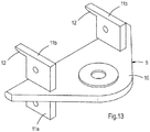
- clamping plates 13 are used, see Fig. 12 .
- Each of the clamping plates 13 has a hook-shaped portion 13', which fits about the plate 7 of the waling beam 2.
- the lower and upper cross plates 11a, 11b are screwed to the respective clamping plates 13 by bolt-nut-joints.
- the corresponding bolt holes in the cross plates 11a, 11b and the clamping plates 13 are visible in Figs. 12 and 13 .
- the hook-shaped portions 13' of the clamping plates 13 together constitute a brace for attaching the coupling piece 9 and the waling beams 2 to each other in a direction perpendicular to the outer side of the waling beam 2.
- Figs. 8-12 show a situation in which the coupling piece 9 does not need to absorb a force in longitudinal direction of the waling beam 2, hence in the event that the push bar 15 extends perpendicularly to the waling beam 2.
- Fig. 11 shows how an end portion of a push bar 15 of the strut 3 is mounted to the coupling piece 9 by means of a coupling pin 14.
- the push bar 15 exerts a force on the waling beam 2 through the coupling piece 9 the horizontal force is mainly transmitted by the main plate 10.
- the main plate 10 can slightly project with respect to the lower and upper cross plates 11a, 11b in the direction of the waling beam 2.
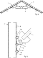
- Figs. 14 and 15 show a situation in which the diagonal strut 4 is coupled with two waling beams 2 which are angled with respect to each other.
- Fig. 15 shows that the coupling piece 9 for the coupling with the diagonal strut 4 has a different shape and dimension than the one for the coupling with the strut 3 as shown in Fig. 9 , because the coupling piece 9 of the diagonal strut 4 must transmit larger forces in the longitudinal direction of the waling beam 2.
- the coupling piece 9 has three lower cross plates 11a and three upper cross plates 11b, which extend perpendicularly to the main plate 10.
- There are also six clamping plates 13 for fixing the coupling piece 9 to the waling beam 2. Nevertheless, the coupling pieces 9 for both applications make use of the same coupling elements 7a of the waling beam 2.
- Fig. 16 shows a part of Fig. 1 on a larger scale.
- the three waling beams 2 which are located above each other together support the sheet pile wall 1.
- the strut system is further provided with three independent push bars 15 for exerting respective pushing forces on the respective waling beams 2 through the respective coupling pieces 9.
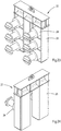
- the push bars 15 are part of a strut member 16, which can be seen in more detail in Fig. 18 and 19 .
- the strut member 16 in turn is part of the strut 3 as shown in Figs. 1 and 2 .
- the strut member 16 is provided with a frame 17 including a flange 17a through which the strut member 16 is attached to the remainder of the strut 3.
- the frame 17 has three guides 18 in the form of tubes for guiding the respective push bars 15 (the push bars 15 are not shown in Figs. 18 and 19 ).
- the inner one of the three guides 18 is directly connected to the two outer guides 18 through intermediate plates 19.
- the two outer guides 18 are directly connected to each other through shells 20.
- the three push bars 15 are extendible in the same direction with respect to the frame 17.
- the centrelines of the push bars 15 lie in one plane and the distance between two neighbouring push bars 15 is equal.
- Each guide 18 forms a cylinder, which is closed at one side by the push bar 15 in de extended condition and which is closed at the opposite side by a plate.
- Each of the guides 18 is provided with a hole for filling the cylinder with sand. This constitutes a locking system for fixing the push bars 15 in the extended condition with respect to the frame 17.
- sealable discharge openings are applied in order to unlock the lock. When the strut 3 must be removed the sand can be discharged easily through these discharge holes in order to remove pressure on the push bars 15 and to slide the push bars 15 into the guides 18.
- Figs. 20-22 show different views of a press unit 23 which can be placed against the frame 17 of the strut member 16 in order to place the strut 3 against the three waling beams 2 and exert the desired pressure on the waling beams 2.
- Figs. 23 and 24 show the press unit 23 as a separate apparatus.
- the press unit 23 is provided with three pairs of jacks in the form of hydraulic cylinders 24.
- hydraulic cylinders 24 are present at either side of each push bar 15, which hydraulic cylinders 24 are connectable to the push bar 15 through a connecting piece 26.
- the ends of the cylinders 24 at the side of the waling beam 2 are provided with ridges which fit in respective grooves of the connecting piece 26.
- the connecting piece 26 in turn is coupled to the coupling piece 9.
- the press unit 23 has a U-shaped basis 25 on which the hydraulic cylinders 24 are mounted, which basis 25 can be placed across the push bars 15 such that it abuts a front side of the frame 17 of the strut member 16, as shown in Figs. 20-22 . Consequently, the hydraulic cylinders 24 can push against the frame 17 in the coupled condition.
- the press unit 23 can be detached form the strut member 16 and be used for placing a next strut 3.
- the waling beams 2 are kept at a distance from each other by calibration blocks 27. Due to manufacturing variations of the waling beams 2 there are deviations of the dimensions of the plates 7 with respect to the web 6 in practice. In order to have the push bars 15 of the strut member 16 engaging the waling beams 2 at the height levels of the webs 6 the distance between the webs 6 is kept at a desired distance by the calibration blocks 27. This also means that space for lifting eyes can be created between the waling beams 2.
- both waling beams are put under pressure by a single hydraulic cylinder through a plate which contacts the hydraulic cylinder at one side thereof and contacts both waling beams at the other side thereof.
- a plate which contacts the hydraulic cylinder at one side thereof and contacts both waling beams at the other side thereof.
- a hydraulic cylinder exerts a force on one of the waling beams and a fixed connection or strut between the waling beam and an opposite wall is applied, after which the hydraulic cylinder is used for exerting a force on the second waling beam, after which a fixed connection or strut is applied between the second waling beam and an opposite wall.
- the independent push bars 15 and the strut member 16 as described above eliminate these drawbacks.
- the strut member 16 and the press unit may also be used for the diagonal struts 4 as can be seen in Fig. 1 .
- an aspect of the invention comprises a strut member for supporting a plurality of waling beams which are located above each other for retaining a retaining wall, wherein the strut member is provided with a frame, which comprises at least two guides for guiding respective push bars, wherein the push bars are extendable in the same direction with respect to the frame through the respective guides, and a locking system for locking the push bars in a certain extended condition with respect to the frame.
- the strut member comprises three guides including three extendable push bars, of which the centrelines lie in one plane and the distance between two neighbouring push bars is equal.
- the inner one of the three guides is directly connected to both outer guides and the outer guides are directly connected to each other through curved plates.
- Each guide may comprise a cylinder, which is closed at one side by the cooperating push bar and which is closed at the opposite side by a closure which is fixed to the frame, wherein the cylinder is provided with a filling hole for filling the cylinder with an incompressible fluid so as to form the locking system.
- an aspect of the invention also comprises a method for pushing two waling beams being located above each other against a retaining wall, wherein two independent jacks or hydraulic cylinders simultaneously exert respective pushing forces on the respective waling beams.
- the positions of the waling beams at the jacks or hydraulic cylinders may be locked by means of push bars or struts, after which the jacks or hydraulic cylinders may be removed. Setting the pressure of the jacks or the hydraulic pressure such that the pushing forces are more less equal, it is assured that the retaining wall is supported by both waling beams.
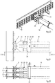
- Figs. 25-27 show an alternative embodiment of the assembly according to the invention.
- Both opposite outer sides of the waling beam 2 are provided with the pairs of notch plates 8a, 8b which are located at a distance from each other.
- the notch plates 8a, 8b lie against the sheet pile wall 1 in this case.
- the coupling piece 9 is a shear piece which locks the waling beam 2 in its longitudinal direction with respect to the sheet pile wall 1.
- such a connection is desired at a building excavation, which is separated from the surrounding ground by a U-shaped sheet pile wall. Since the waling beams 2 are retained against the basis of the U-shape in only one longitudinal direction along the legs of the U-shape, it may be desired to fix the waling beams in the opposite direction with respect to the sheet pile wall.
- Figs. 25-27 The parts which are similar to the parts in the embodiments as described above are indicated by the same reference numbers in Figs. 25-27 . Similar to the embodiments as described hereinbefore the coupling piece 9 according to Figs. 25-27 can be coupled to the waling beam 2 at different locations along the waling beam 2.
- the main plate 10 has chamfered sides.
- Fig. 26 shows that in assembled condition one of these sides abuts a wall of a recess in the sheet pile wall 1 which extends transversely to the waling beam 2.
- the shear piece is mounted to the waling beam 2 in a similar way as the coupling pieces 9 as described hereinbefore, for example by means of the clamping plates 13.
Landscapes
- Engineering & Computer Science (AREA)
- Mining & Mineral Resources (AREA)
- Life Sciences & Earth Sciences (AREA)
- General Life Sciences & Earth Sciences (AREA)
- Paleontology (AREA)
- Civil Engineering (AREA)
- General Engineering & Computer Science (AREA)
- Structural Engineering (AREA)
- Joining Of Building Structures In Genera (AREA)
- Pit Excavations, Shoring, Fill Or Stabilisation Of Slopes (AREA)
Applications Claiming Priority (1)
| Application Number | Priority Date | Filing Date | Title |
|---|---|---|---|
| NL2022395A NL2022395B1 (nl) | 2019-01-14 | 2019-01-14 | Samenstel van een gordingbalk en een koppelstuk |
Publications (1)
| Publication Number | Publication Date |
|---|---|
| EP3680392A1 true EP3680392A1 (de) | 2020-07-15 |
Family
ID=65763716
Family Applications (1)
| Application Number | Title | Priority Date | Filing Date |
|---|---|---|---|
| EP20151592.1A Withdrawn EP3680392A1 (de) | 2019-01-14 | 2020-01-14 | Aufbau eines riegelträgers und eines kupplungsstücks |
Country Status (2)
| Country | Link |
|---|---|
| EP (1) | EP3680392A1 (de) |
| NL (1) | NL2022395B1 (de) |
Cited By (3)
| Publication number | Priority date | Publication date | Assignee | Title |
|---|---|---|---|---|
| JP2022096077A (ja) * | 2020-12-17 | 2022-06-29 | 株式会社エステクノ | 腹起し矯正治具及び山留壁構築工法 |
| WO2025251138A1 (en) * | 2024-06-03 | 2025-12-11 | Saskarc Inc. | Method for factory prefabrication of a customized site-specific modular wall-reinforcement kit for reinforcement of support of excavation (soe) walls |
| EP4726108A1 (de) * | 2024-10-11 | 2026-04-15 | Key Staal B.V. | Strebenstruktur für eine baugrube und verfahren zur verriegelung der strebenstruktur |
Citations (6)
| Publication number | Priority date | Publication date | Assignee | Title |
|---|---|---|---|---|
| DE2135275A1 (de) * | 1971-07-15 | 1973-01-25 | Gruen & Bilfinger Ag | Stuetztopf |
| DE29918383U1 (de) * | 1999-10-19 | 2000-08-31 | SBH Tiefbautechnik GmbH, 52525 Heinsberg | Verbauvorrichtung mit Gurtungsträgern |
| US20030031514A1 (en) * | 2001-07-20 | 2003-02-13 | Leslie Nicholson | Support structure |
| WO2007058464A1 (en) * | 2005-11-16 | 2007-05-24 | Supportec Co., Ltd. | Temporary soil sheathing apparatus |
| KR20120055236A (ko) | 2010-11-23 | 2012-05-31 | 이진욱 | 조립식 버팀보 연결 구조체 |
| GB2530292A (en) * | 2014-09-17 | 2016-03-23 | Glenn Roy Wood | Trench wall support |
-
2019
- 2019-01-14 NL NL2022395A patent/NL2022395B1/nl active
-
2020
- 2020-01-14 EP EP20151592.1A patent/EP3680392A1/de not_active Withdrawn
Patent Citations (6)
| Publication number | Priority date | Publication date | Assignee | Title |
|---|---|---|---|---|
| DE2135275A1 (de) * | 1971-07-15 | 1973-01-25 | Gruen & Bilfinger Ag | Stuetztopf |
| DE29918383U1 (de) * | 1999-10-19 | 2000-08-31 | SBH Tiefbautechnik GmbH, 52525 Heinsberg | Verbauvorrichtung mit Gurtungsträgern |
| US20030031514A1 (en) * | 2001-07-20 | 2003-02-13 | Leslie Nicholson | Support structure |
| WO2007058464A1 (en) * | 2005-11-16 | 2007-05-24 | Supportec Co., Ltd. | Temporary soil sheathing apparatus |
| KR20120055236A (ko) | 2010-11-23 | 2012-05-31 | 이진욱 | 조립식 버팀보 연결 구조체 |
| GB2530292A (en) * | 2014-09-17 | 2016-03-23 | Glenn Roy Wood | Trench wall support |
Cited By (3)
| Publication number | Priority date | Publication date | Assignee | Title |
|---|---|---|---|---|
| JP2022096077A (ja) * | 2020-12-17 | 2022-06-29 | 株式会社エステクノ | 腹起し矯正治具及び山留壁構築工法 |
| WO2025251138A1 (en) * | 2024-06-03 | 2025-12-11 | Saskarc Inc. | Method for factory prefabrication of a customized site-specific modular wall-reinforcement kit for reinforcement of support of excavation (soe) walls |
| EP4726108A1 (de) * | 2024-10-11 | 2026-04-15 | Key Staal B.V. | Strebenstruktur für eine baugrube und verfahren zur verriegelung der strebenstruktur |
Also Published As
| Publication number | Publication date |
|---|---|
| NL2022395B1 (nl) | 2020-08-14 |
Similar Documents
| Publication | Publication Date | Title |
|---|---|---|
| US6416259B1 (en) | Corner connection for temporary shoring | |
| CA2217124C (en) | Apparatus and method for a modular support and lifting system | |
| US6161342A (en) | Prefabricated concrete element for building a civil engineering structure having an arched wall | |
| US7883296B2 (en) | Shoring beam extension and reinforcement assembly | |
| US6984092B1 (en) | Corner connection for temporary shoring | |
| AU2018204385B2 (en) | Formwork for performing castings for providing floor slabs | |
| KR101357775B1 (ko) | 엔드플레이트를 이용한 버팀보 연결장치 | |
| KR102402921B1 (ko) | 스마트 커넥팅 멤버를 이용한 샌드위치 피씨패널 연결구조 및 그 연결방법 | |
| NL2022395B1 (nl) | Samenstel van een gordingbalk en een koppelstuk | |
| US20050232742A1 (en) | Quick-coupler device | |
| US5080533A (en) | Safety shield for an excavation trench | |
| GB1585700A (en) | Concrete form system | |
| WO2008100026A1 (en) | Composite girder with steel truss web having hinge connecting, and connection structure thereof | |
| DK2802715T3 (en) | PRESSURE CONNECTION FRAME FOR A ABSENT FORM | |
| EP3924555B1 (de) | Verfahren zur verstrebung von stützbeinen in einer erdrückhaltestruktur eines aushubsicherungssystems und elementsystem zur durchführung dieses verfahrens | |
| US20220010569A1 (en) | Scaffolding post connection rosette with hollow embossments of reduced nominal thickness, and scaffolding subassembly | |
| KR102491433B1 (ko) | 보데크 프레임 및 이를 이용하여 형성된 보데크 | |
| KR102495555B1 (ko) | 사다리난간형 토류벽 구조 및 이의 시공 방법 | |
| EP3315691A1 (de) | Gerüste für gebäude und industriegebäude mit verbindungssystem | |
| JP6910101B1 (ja) | コンクリート構造物用型枠装置及びコンクリート構造物の型枠工法 | |
| KR20200012640A (ko) | 완속 하중전이가 가능한 하중 재하중인 기둥 안전철거 구조물 및 철거방법 | |
| KR200253550Y1 (ko) | 철근콘크리트 구조물 교각고핑의 유압식 받침구조 | |
| FI58672B (fi) | Kopplingsanordning foer exempelvis byggnadsstaellningselement | |
| KR200436405Y1 (ko) | 버팀보 보강용 브레이싱 서포트 체결구조 | |
| EP0072817A1 (de) | Zerlegbares gerüst |
Legal Events
| Date | Code | Title | Description |
|---|---|---|---|
| PUAI | Public reference made under article 153(3) epc to a published international application that has entered the european phase |
Free format text: ORIGINAL CODE: 0009012 |
|
| STAA | Information on the status of an ep patent application or granted ep patent |
Free format text: STATUS: THE APPLICATION HAS BEEN PUBLISHED |
|
| AK | Designated contracting states |
Kind code of ref document: A1 Designated state(s): AL AT BE BG CH CY CZ DE DK EE ES FI FR GB GR HR HU IE IS IT LI LT LU LV MC MK MT NL NO PL PT RO RS SE SI SK SM TR |
|
| AX | Request for extension of the european patent |
Extension state: BA ME |
|
| STAA | Information on the status of an ep patent application or granted ep patent |
Free format text: STATUS: REQUEST FOR EXAMINATION WAS MADE |
|
| 17P | Request for examination filed |
Effective date: 20210113 |
|
| RBV | Designated contracting states (corrected) |
Designated state(s): AL AT BE BG CH CY CZ DE DK EE ES FI FR GB GR HR HU IE IS IT LI LT LU LV MC MK MT NL NO PL PT RO RS SE SI SK SM TR |
|
| STAA | Information on the status of an ep patent application or granted ep patent |
Free format text: STATUS: EXAMINATION IS IN PROGRESS |
|
| 17Q | First examination report despatched |
Effective date: 20240523 |
|
| STAA | Information on the status of an ep patent application or granted ep patent |
Free format text: STATUS: THE APPLICATION HAS BEEN WITHDRAWN |
|
| 18W | Application withdrawn |
Effective date: 20241010 |