EP3680195B1 - Zusätzlicher deckel für gewellten behältersumpf - Google Patents
Zusätzlicher deckel für gewellten behältersumpf Download PDFInfo
- Publication number
- EP3680195B1 EP3680195B1 EP20151532.7A EP20151532A EP3680195B1 EP 3680195 B1 EP3680195 B1 EP 3680195B1 EP 20151532 A EP20151532 A EP 20151532A EP 3680195 B1 EP3680195 B1 EP 3680195B1
- Authority
- EP
- European Patent Office
- Prior art keywords
- valve
- cover
- coupled
- seal
- microprocessor
- Prior art date
- Legal status (The legal status is an assumption and is not a legal conclusion. Google has not performed a legal analysis and makes no representation as to the accuracy of the status listed.)
- Active
Links
Images


Classifications
-
- B—PERFORMING OPERATIONS; TRANSPORTING
- B65—CONVEYING; PACKING; STORING; HANDLING THIN OR FILAMENTARY MATERIAL
- B65D—CONTAINERS FOR STORAGE OR TRANSPORT OF ARTICLES OR MATERIALS, e.g. BAGS, BARRELS, BOTTLES, BOXES, CANS, CARTONS, CRATES, DRUMS, JARS, TANKS, HOPPERS, FORWARDING CONTAINERS; ACCESSORIES, CLOSURES, OR FITTINGS THEREFOR; PACKAGING ELEMENTS; PACKAGES
- B65D90/00—Component parts, details or accessories for large containers
- B65D90/10—Manholes; Inspection openings; Covers therefor
- B65D90/105—Manholes; Inspection openings; Covers therefor for underground containers
-
- E—FIXED CONSTRUCTIONS
- E02—HYDRAULIC ENGINEERING; FOUNDATIONS; SOIL SHIFTING
- E02D—FOUNDATIONS; EXCAVATIONS; EMBANKMENTS; UNDERGROUND OR UNDERWATER STRUCTURES
- E02D29/00—Independent underground or underwater structures; Retaining walls
- E02D29/12—Manhole shafts; Other inspection or access chambers; Accessories therefor
- E02D29/14—Covers for manholes or the like; Frames for covers
- E02D29/149—Annular gaskets
-
- F—MECHANICAL ENGINEERING; LIGHTING; HEATING; WEAPONS; BLASTING
- F16—ENGINEERING ELEMENTS AND UNITS; GENERAL MEASURES FOR PRODUCING AND MAINTAINING EFFECTIVE FUNCTIONING OF MACHINES OR INSTALLATIONS; THERMAL INSULATION IN GENERAL
- F16L—PIPES; JOINTS OR FITTINGS FOR PIPES; SUPPORTS FOR PIPES, CABLES OR PROTECTIVE TUBING; MEANS FOR THERMAL INSULATION IN GENERAL
- F16L55/00—Devices or appurtenances for use in, or in connection with, pipes or pipe systems
- F16L55/10—Means for stopping flow in pipes or hoses
- F16L55/12—Means for stopping flow in pipes or hoses by introducing into the pipe a member expandable in situ
- F16L55/128—Means for stopping flow in pipes or hoses by introducing into the pipe a member expandable in situ introduced axially into the pipe or hose
- F16L55/132—Means for stopping flow in pipes or hoses by introducing into the pipe a member expandable in situ introduced axially into the pipe or hose the closure device being a plug fixed by radially deforming the packing
- F16L55/134—Means for stopping flow in pipes or hoses by introducing into the pipe a member expandable in situ introduced axially into the pipe or hose the closure device being a plug fixed by radially deforming the packing by means of an inflatable packing
-
- B—PERFORMING OPERATIONS; TRANSPORTING
- B65—CONVEYING; PACKING; STORING; HANDLING THIN OR FILAMENTARY MATERIAL
- B65D—CONTAINERS FOR STORAGE OR TRANSPORT OF ARTICLES OR MATERIALS, e.g. BAGS, BARRELS, BOTTLES, BOXES, CANS, CARTONS, CRATES, DRUMS, JARS, TANKS, HOPPERS, FORWARDING CONTAINERS; ACCESSORIES, CLOSURES, OR FITTINGS THEREFOR; PACKAGING ELEMENTS; PACKAGES
- B65D2590/00—Component parts, details or accessories for large containers
- B65D2590/0083—Computer or electronic system, e.g. GPS systems
Definitions
- containment sumps, underground storage tanks, sanitary sewers and other underground systems are buried below the frost line of the terrain surrounding the underground system. Access to these underground systems is oftentimes achieved through an opening or access point at ground level. These openings or access points may be large enough to provide physical access or entry into the system and a ground level cover may be utilized to enclose or block access to the opening.
- a secondary access point may be constructed and a lid or secondary cover may be utilized to further confine access into the underground system.
- a ground cover may restrict the flow of water or debris into the underground system, water and other liquids tend to find the paths of least resistance and may find their way around the ground cover and into the underground system. Further, many freeze/thaw cycles, erosion, or other influences may shift the ground cover or otherwise create a path for liquids to leak into the system. Also, the expansions and contractions of the system may further compromise the system.
- An underground storage tank top sump is a generic term for a liquid-tight container installed on top of an underground storage tank designed to house various tank components.
- Tank top sumps serve a variety of functions including providing a juncture for piping systems, pumps, and other tank components.
- the sump may further serve to isolate the components from the corrosive effects of subsurface moisture and soil.
- Prior devices have been described that attempt to create a secondary access point into the underground system, however the components within the underground system may still suffer from corrosion within the sealed system.
- No known prior device describes a cover for a secondary access point that includes an inflatable seal that redundantly seals against a corrugated sidewall and that may further release nitrogen into the sealed system to reduce corrosion within the sealed system.
- Documents WO2017/052707A1 and US6682257B1 describe lids and document US2013/264341A1 describes a thief hatch.
- a secondary lid according to claim 1 A second tank containing compressed nitrogen may be pneumatically coupled to the fourth valve.
- the microprocessor may selectively open and close the fourth valve to thereby selectively control flow of gas from the first and second tanks.
- a fifth valve may be pneumatically coupled inline between the fourth valve and the second valve, and further coupled to the microprocessor, wherein the microprocessor further controls actuation of the fifth valve.
- the microprocessor may actuate the fourth and fifth valves to release nitrogen from the fifth valve into a space below the cover within the secondary access port.
- a pressure gauge may be pneumatically coupled inline between the fourth valve and the fifth valve, and further coupled to the microprocessor, wherein the microprocessor may further control actuation of the fourth and fifth valves to control the pressure within the pneumatic seal.
- the microprocessor may include a wireless communicator to couple wirelessly to an external controller. In this manner the microprocessor may be further utilized to remotely monitor and control inflation and deflation of the pneumatic seal.
- a pressure sensor may be coupled to the microprocessor to provide data related to a pressure value corresponding to the space below the cover and within the secondary access port. In this manner the microprocessor may be utilized to release nitrogen into the sealed space below the cover to maintain a desired pressure within the sealed space.
- the supplemental lid control system 10 of the present invention is particularly well suited for use in a secondary containment system.
- the supplemental lid control system may be utilized to restrict flow of liquid into an underground containment system.
- the underground system will be described in the context of underground storage tanks and containment sumps coupled to the underground storage tank.
- the supplemental lid control system 10 includes a supplemental lid 100 having structure and components described below in greater detail.
- the supplemental lid 100 and sump 170 cooperate together to create a barrier that restricts water from penetrating into the interior of an underground system.
- the lid 100 includes an inflatable seal 30, at least one tank 14 having a compressed gas contained within the tank, at least an inflate control valve 70 and a deflate control valve 74, and a pneumatic conduit or line 34 that pneumatically interconnects the seal 30 and tank 70.
- the inflate control valve 70 and deflate control valve 74 are of a known suitable construction which may be hand operated or solenoid driven.
- a third valve 78 may be coupled to the lid 100 to allow oxygen to purge when the lid 100 is sealed to the sump 170.
- the secondary or supplemental lid 100 restricts inflow of fluids into an interior of a containment sump 170 of an underground storage tank.
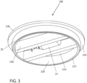
- the secondary lid 100 may be described further as having a cover 110 having a top surface 112 and a bottom surface 114.
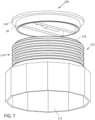
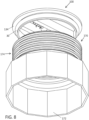
- a ring 120 that is concentric with the cover 110, extends downwardly from the bottom surface 114 of the cover 110 to a free end 122 of the ring 120.
- a flange 130 extends outwardly from at least one of the cover 110 and the ring 120.
- the annular expandable pneumatic seal 30 engages to an outer surface 124 of the ring 120, wherein when the seal 30 is expanded the seal 30 expands outwardly, and expands upwardly towards the flange 130, and expands downwardly towards the free end 122 of the ring 120.
- the primary or first tank 14 containing compressed gas is coupled in fluid communication with the pneumatic seal 30.
- the first valve or inflation control valve 70 is coupled inline between the first tank 14 of compressed gas and the pneumatic seal 30, wherein the first valve 70 actuates between an open and closed position to control inflation of the pneumatic seal 30 and delivery of gas from the first tank 14 to the pneumatic seal 30.
- the second valve or deflation control valve 74 is coupled to the pneumatic seal 30 wherein the second valve 74 actuates between an open and closed position to control deflation of the pneumatic seal 30 and a release of gas from the seal 30 into space below the cover 110.
- the primary tank 14 includes a regulator 16 to control the pressure of the gas delivered from the tank 14 to the inflate control valve 70.
- Valve 70 may be actuated between an open and closed positions to provide a supply of gas to valves 86 and 74.
- Gauge 50 is pneumatically coupled inline and fixed to the cover 110 in a manner to allow visual monitoring of the pressure of the gas being delivered to the seal 30.
- the primary tank 14 may be additionally pneumatically coupled to valve 82.
- Secondary Tank 18 has a regulator 20 and is also pneumatically coupled to the valve 82.
- Valve 82 has multiple open and closed positions and may be actuated between the various positions by a solenoid.
- the solenoid is electrically coupled to micro controller or processor 40.
- a signal is electrically sent over electrical circuit 36 from the microprocessor to the valve 82 to open and close the valve to allow flow of gas from either the primary tank 14 or secondary tank 18.
- the microcontroller 40 may be further electrically coupled to a solenoid actuated valve 86. When the valve is in the closed position gas flows through the valve to valve 74. When the microprocessor opens valve 86 gas flows from the valve into the internal space below the lid 100. In this manner the user may choose to deliver gas into the sealed sump area.
- the microprocessor 40 is further powered by power supply or battery 42 and includes the necessary electrical components to send and receive wireless signals 44.
- An external controller is wirelessly linked to the controller to allow control and actuation of the valves externally.
- the microprocessor 40 may further control actuation of valves 82 and 86 dependent upon the values received from sensor 60.
- valve 74 is typically in the open position to allow flow of gas from the pneumatic conduit or line 34 to the seal 30.
- a user may deliver pressurized air to the inflatable seal without removing the lid from the support frame16.
- an internal pressure ranging between 3-15psi has been found sufficient to engage the seal 30 to an inner sidewall 174 of sump 170 with enough force against the sidewall to reduce the likelihood that the lid is removed without first deflating the seal.
- the pressure within inflatable seal may be varied to compensate for changes in the environmental temperature surrounding the lid.
- valves 70, 82 and 74 are in the closed position to restrict flow of gas to seal 30. Further, when valve 74 is closed the gas within seal 30 is released into the internal space 102 of the sump 170. Compressed nitrogen gas may be delivered to seal 30. When nitrogen is released into the sump 170 any oxygen present in the sump 170 tends to rise to the bottom surface 114 of the cover 110.
- One way release valve 78 is coupled to cover 110 to form a conduit between the bottom surface 114 of the cover and the top surface 112 of the cover 110.
- the release valve 78 actuates open to allow gases to flow through the valve from the space below the cover to space above the cover.
- One way release valve 78 allows oxygen to escape out of the sump without allowing air into the enclosed sump. In this manner, nitrogen gas may be intentionally released into the sump from valve 86 to reduce corrosion of components contained within the sump.
- the supplemental lid 100 includes a cover 110 having a top surface 112 and bottom surface 114.
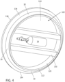
- Handle 104 is attached to the top surface 112 of the cover 110.
- the handle 104 includes recesses that serve as guards for valve 70 and valve 74.
- a portion of each valve 70 and 74 extends through cover 110 and is coupled to the cover.
- the actuating mechanism for each valve extends from the cover 110 into the recesses of the handle 104. In this manner the valves are protected or guarded from unintentional bumps or activation.
- Ring 120 extends from the bottom surface 114 of the cover 110 to a free end 122 of the ring 120. Seal 30 engages to an outside surface 124 of the ring 120.
- the ring 120 is concentric with the cover 110.
- Flange 130 extends outwardly from the ring 120 or cover 110 at a connection point 126.
- the flange includes a top 132, bottom 134 and outer edge 136.
- the bottom 134 of the flange 130 rests on a top end 176 of sump 170.
- the bottom 114 of the cover 110 may include internal supports 150 that span between opposing sides of the ring 120. The internal supports may be utilized to couple and secure the various components of the supplemental lid control system 10 to the bottom of the cover 120 within the internal space 102 of the lid 100.
- the diameter of the supplemental lid 100 and sump sidewall 174 are typically sized to allow passage there through by a user. Municipalities or cities often times will specify the minimum requirements for this opening.
- the lid 100 may be made of a suitable construction and, by way of example, may preferably be made from a combination of fiberglass and plastic.
- the inflatable seal 30 is preferably made of an expandable polymer or rubber.
- the seal 30 includes a hollow internal airway or central section to which air may delivered. As the air pressure within the internal airway increases the seal tends to expand and as the air pressure decreases the internal airway tends to relax and contract.
- the pneumatic seal 30 engages to a sidewall 174 of the sump 170, wherein when the seal is expanded the seal expands outwardly, and expands upwardly towards the flange 130, and expands downwardly towards the free end 122 of the ring or collar 120 such that the seal 30 engages with the cylindrical sidewall 174 when the flange 130 engages the top end 176 of the secondary access port or sump 170.
- the sump 170 includes a base 172 that engages with the underground storage tank.
- the cylindrical sidewall 174 extends from the base 172 thereby forming a portion of the secondary access port.
- the cylindrical sidewall 174 is corrugated and has spaced apart ribs 178 forming a portion of the cylindrical sidewall 174. Valleys 180 interconnect the spaced apart ribs 178.
- the pneumatic seal 30 When the pneumatic seal 30 is inflated the seal expands outwardly and engages with at least one rib 178 of the cylindrical sidewall and with a valley 180 or other portion of the cylindrical sidewall between two spaced apart ribs178.
- the seal may have at least a two point contact with the sidewall 174 to create a redundant seal between the lid 100 and sump 170.
- the lid 100 rest on the top of sump 170.
- the inflatable seal 30 of the lid 100 engages the inner surface of the sidewall 174 of the sump 170.
- the user may depress or activate the inflation valve control 70 to open the valve 70 and deliver nitrogen or gas from pressurized tank 70 into the inflatable seal 30.
- the user may continue to depress the inflation valve 70 until the desired air pressure within the pneumatic seal 30 is indicated on the external pressure gauge 50.
- the user depresses or activates the discharge or deflation control valve 74 to release the nitrogen from the conduit 34 and seal 30.
- Microprocessor 40 couples wirelessly to an external control to allow autonomous control of the inflating and deflating of the seal 30 or release of nitrogen gas into the sealed sump 170.
Landscapes
- Engineering & Computer Science (AREA)
- General Engineering & Computer Science (AREA)
- Mechanical Engineering (AREA)
- Environmental & Geological Engineering (AREA)
- Life Sciences & Earth Sciences (AREA)
- General Life Sciences & Earth Sciences (AREA)
- Mining & Mineral Resources (AREA)
- Paleontology (AREA)
- Civil Engineering (AREA)
- Structural Engineering (AREA)
- Filling Or Discharging Of Gas Storage Vessels (AREA)
- Underground Structures, Protecting, Testing And Restoring Foundations (AREA)
Claims (6)
- Sekundärdeckel zum Beschränken von Zufluss von Fluids in das Innere einer Auffangwanne eines unterirdischen Lagertanks, welcher eine sekundäre Zugangsöffnung aufweist, wobei der Sekundärdeckel (100) umfasst:eine Abdeckung (110) mit einer oberen (112) und einer unteren (114) Oberfläche;einen Ring (120), welcher konzentrisch mit der Abdeckung ist, wobei sich der Ring von der unteren Oberfläche der Abdeckung nach unten zu einem freien Ende des Rings erstreckt;einen Flansch (130), welcher sich von zumindest einem von der Abdeckung und dem Ring nach außen erstreckt;eine ringförmig dehnbare pneumatische Dichtung (30), welche in eine äußere Oberfläche des Rings eingreift, wobei, wenn die Dichtung gedehnt ist, die Dichtung sich nach außen dehnt, und sich nach oben zu dem Flansch hin dehnt, und sich nach unten zu dem freien Ende des Rings dehnt;einen ersten Behälter (14), welcher ein komprimiertes Gas enthält, und der erste Behälter in Fluidverbindung mit der pneumatischen Dichtung gekoppelt ist;ein erstes Ventil (70), welches linear zwischen dem ersten Behälter mit komprimiertem Gas und der pneumatischen Dichtung gekoppelt ist, wobei das erste Ventil dazu konfiguriert ist, zwischen einer offenen und geschlossenen Position betätigt zu werden, um Aufblasen der pneumatischen Dichtung und Abgabe von Gas aus dem ersten Behälter an die pneumatische Dichtung zu steuern; ein zweites Ventil (74), welches in Serie zu der pneumatischen Dichtung gekoppelt ist, wobei das zweite Ventil dazu konfiguriert ist, zwischen einer offenen und geschlossenen Position betätigt zu werden, um Entleeren der pneumatischen Dichtung und Ablassen von Gas aus der Dichtung in Raum unterhalb der Abdeckung zu steuern;ein drittes Ventil (78), welches an die Abdeckung gekoppelt ist, um einen Kanal zwischen der unteren Oberfläche der Abdeckung und der oberen Oberfläche der Abdeckung zu bilden, wobei das dritte Ventil dazu konfiguriert ist, betätigt zu werden, um zu erlauben, dass Gase aus dem Raum unterhalb der Abdeckung durch das dritte Ventil in Raum oberhalb der Abdeckung fließen; gekennzeichnet durchein viertes Ventil (82), welches linear zwischen dem ersten Behälter und pneumatischer Dichtung gekoppelt ist, wobei das vierte Ventil magnetisch zwischen offener und geschlossener Position betätigt werden kann, und weiter einen Mikroprozessor (40) beinhaltend, welcher mit dem vierten Ventil gekoppelt ist, wobei der Mikroprozessor dazu konfiguriert ist, Betätigung des vierten Ventils zu steuern.
- Sekundärdeckel gemäß Anspruch 1, weiter einen zweiten Behälter (18) beinhaltend, welcher komprimierten Stickstoff enthält, welcher pneumatisch mit dem vierten Ventil gekoppelt ist; wobei optional der Mikroprozessor dazu konfiguriert ist, das vierte Ventil selektiv zu öffnen und zu schließen, um Gasfluss aus dem ersten und zweiten Behälter zu steuern.
- Sekundärdeckel gemäß Anspruch 2, weiter ein fünftes Ventil (86) beinhaltend, welches linear zwischen dem vierten Ventil und dem zweiten Ventil unterhalb der Abdeckung gekoppelt ist, und weiter mit dem Mikroprozessor gekoppelt ist, wobei der Mikroprozessor weiter dazu konfiguriert ist, Betätigung des vierten und fünften Ventils zu steuern, um Stickstoffgas aus dem fünften Ventil in Raum unterhalb der Abdeckung freizusetzen.
- Sekundärdeckel gemäß Anspruch 3, weiter ein Manometer (50) beinhaltend, welches linear zwischen dem vierten Ventil und dem fünften Ventil pneumatisch gekoppelt ist, und weiter mit dem Mikroprozessor gekoppelt ist, wobei der Mikroprozessor weiter dazu konfiguriert ist, Betätigung des vierten und fünften Ventils zu steuern, um den Druck innerhalb der pneumatischen Dichtung zu steuern.
- Sekundärdeckel gemäß einem der Ansprüche 1 bis 4, wobei der Mikroprozessor ein drahtloses Kommunikationsgerät (44) beinhaltet, um drahtlos an eine externe Steuerung gekoppelt zu werden.
- Sekundärdeckel gemäß einem der Ansprüche 1 bis 5, weiter einen Drucksensor (60) beinhaltend, welcher mit dem Mikroprozessor gekoppelt ist, um Daten in Bezug auf einen Druckwert bereitzustellen, welcher dem Raum unterhalb der Abdeckung entspricht.
Applications Claiming Priority (1)
| Application Number | Priority Date | Filing Date | Title |
|---|---|---|---|
| US16/245,911 US10870534B2 (en) | 2019-01-11 | 2019-01-11 | Supplemental lid for corrugated containment sump |
Publications (4)
| Publication Number | Publication Date |
|---|---|
| EP3680195A2 EP3680195A2 (de) | 2020-07-15 |
| EP3680195A3 EP3680195A3 (de) | 2020-09-30 |
| EP3680195B1 true EP3680195B1 (de) | 2024-07-24 |
| EP3680195C0 EP3680195C0 (de) | 2024-07-24 |
Family
ID=69165303
Family Applications (1)
| Application Number | Title | Priority Date | Filing Date |
|---|---|---|---|
| EP20151532.7A Active EP3680195B1 (de) | 2019-01-11 | 2020-01-13 | Zusätzlicher deckel für gewellten behältersumpf |
Country Status (2)
| Country | Link |
|---|---|
| US (1) | US10870534B2 (de) |
| EP (1) | EP3680195B1 (de) |
Family Cites Families (21)
| Publication number | Priority date | Publication date | Assignee | Title |
|---|---|---|---|---|
| US5052216A (en) | 1983-10-21 | 1991-10-01 | Sharp Bruce R | Containment means for storage tank systems |
| US4512492A (en) * | 1983-12-12 | 1985-04-23 | Graybeal Walter C | Manhole closure with a single liquid impervious, two-way gas pressure relief valve |
| US4685585A (en) | 1986-10-09 | 1987-08-11 | Robbins Howard J | Double wall tank manway system |
| US4932441A (en) * | 1988-05-18 | 1990-06-12 | The Presray Corporation | Nozzle dam seal assembly for nuclear steam generator or the like |
| US5052851A (en) * | 1990-06-21 | 1991-10-01 | Frishauf Stephen H | Emergency maintenance hole cover, and method of installation |
| US5425466A (en) | 1992-11-24 | 1995-06-20 | Convault, Inc. | Combination manway cover and emergency pressure relief apparatus |
| US6024243A (en) | 1996-10-23 | 2000-02-15 | Palazzo; David T. | Double wall storage tank having an outer jacket which is sealed around an aperture and a method for making same |
| US6682257B1 (en) | 2002-03-07 | 2004-01-27 | Raymond Zappe | Cover apparatus for an access opening |
| US20050221358A1 (en) | 2003-09-19 | 2005-10-06 | Carrillo Albert L | Pressure chamber clamp mechanism |
| US7153057B1 (en) * | 2006-02-06 | 2006-12-26 | Anthony Lucas | Securable temporary manhole cover |
| WO2009012563A1 (en) | 2007-07-26 | 2009-01-29 | Chemigreen Inc. | Inflatable fluid conduit plug |
| WO2009128945A2 (en) | 2008-04-16 | 2009-10-22 | Argon Technologies | Systems and methods for inflating an article of outdoor gear or apparel using a dry gas |
| BR112012010664A2 (pt) | 2009-11-04 | 2020-08-25 | Holcim Technology Ltd | dispositivo do plugue do duto de segurança inflável |
| WO2011057290A2 (en) | 2009-11-09 | 2011-05-12 | Argon Technologies, Inc. | Inflatable pad and methods for using same |
| US8360679B2 (en) | 2011-03-29 | 2013-01-29 | Strike Tool, Inc. | Inflow and infiltration cap and seal barrier |
| US8636035B2 (en) | 2011-08-22 | 2014-01-28 | Philip L. Lundman | Dual inflatable plug assembly |
| US9296530B2 (en) | 2012-04-06 | 2016-03-29 | Regulator Technologies Tulsa LLC | Thief hatch |
| US8770889B2 (en) | 2012-06-25 | 2014-07-08 | Scott R. Sharp | Method of waterproofing a containment sump |
| US9227600B2 (en) | 2014-03-12 | 2016-01-05 | Winride International Co., Ltd. | Tire inflator |
| US10571355B2 (en) | 2015-03-27 | 2020-02-25 | Union Tank Car Company | Safety procedure and testing mechanism for valve replacement and leak detection on a tank car |
| US9617070B1 (en) | 2015-09-21 | 2017-04-11 | David D. Russell | Supplemental lid for containment sump |
-
2019
- 2019-01-11 US US16/245,911 patent/US10870534B2/en active Active
-
2020
- 2020-01-13 EP EP20151532.7A patent/EP3680195B1/de active Active
Also Published As
| Publication number | Publication date |
|---|---|
| US20200223627A1 (en) | 2020-07-16 |
| EP3680195A2 (de) | 2020-07-15 |
| EP3680195C0 (de) | 2024-07-24 |
| EP3680195A3 (de) | 2020-09-30 |
| US10870534B2 (en) | 2020-12-22 |
Similar Documents
| Publication | Publication Date | Title |
|---|---|---|
| CN203374258U (zh) | 用于收集逃逸到水域中的流体的防护装置 | |
| US9725894B2 (en) | Fluid backflow management system and method of use thereof | |
| EP3820789B1 (de) | Unterwasserflüssigkeitsspeichereinheit, verfahren zum zusammenbau einer unterwasserflüssigkeitsspeichereinheit, verfahren zur wartung oder reparatur einer unterwasserflüssigkeitsspeichereinheit | |
| GB2331796A (en) | Inflatable bladder valve | |
| US3276481A (en) | Apparatus for controlling liquid flow | |
| CN101027231A (zh) | 位于海底的贮存器 | |
| US5960826A (en) | Fluid storage tank with a spill containment system | |
| US5871031A (en) | Removable three position valve | |
| NO832033L (no) | Anlegg for utvinning av hydrokarboner | |
| CA2999445C (en) | Supplemental lid for containment sump | |
| EP3680195B1 (de) | Zusätzlicher deckel für gewellten behältersumpf | |
| US10451207B2 (en) | Safety system | |
| JP2008518178A (ja) | 遮断アセンブリ | |
| US20050268977A1 (en) | Inflatable flow control apparatus and associated method | |
| US5046354A (en) | Pressurized storage tank with automatic shut-down in case of leakage | |
| US6024242A (en) | Removably insertable internal containment reservoir | |
| US20190195215A1 (en) | Sewage basin pump control support | |
| US20070135003A1 (en) | Apparatus for supporting an object at a controllable depth within a body of water | |
| NO20240308A1 (en) | Subsea fluid storage unit | |
| WO2014130504A1 (en) | Equipment protector with buoyant rim | |
| JP2005127348A (ja) | ガス開閉装置 | |
| KR102646334B1 (ko) | 수도관의 동파방지장치 | |
| WO2004048749A1 (en) | Borehole plug | |
| KR840000752B1 (ko) | 지하 액화가스 저장용 안전장치 | |
| CA2866005C (en) | Pressure relief riser for a production tank |
Legal Events
| Date | Code | Title | Description |
|---|---|---|---|
| PUAI | Public reference made under article 153(3) epc to a published international application that has entered the european phase |
Free format text: ORIGINAL CODE: 0009012 |
|
| STAA | Information on the status of an ep patent application or granted ep patent |
Free format text: STATUS: THE APPLICATION HAS BEEN PUBLISHED |
|
| AK | Designated contracting states |
Kind code of ref document: A2 Designated state(s): AL AT BE BG CH CY CZ DE DK EE ES FI FR GB GR HR HU IE IS IT LI LT LU LV MC MK MT NL NO PL PT RO RS SE SI SK SM TR |
|
| AX | Request for extension of the european patent |
Extension state: BA ME |
|
| PUAL | Search report despatched |
Free format text: ORIGINAL CODE: 0009013 |
|
| AK | Designated contracting states |
Kind code of ref document: A3 Designated state(s): AL AT BE BG CH CY CZ DE DK EE ES FI FR GB GR HR HU IE IS IT LI LT LU LV MC MK MT NL NO PL PT RO RS SE SI SK SM TR |
|
| AX | Request for extension of the european patent |
Extension state: BA ME |
|
| RIC1 | Information provided on ipc code assigned before grant |
Ipc: E02D 29/14 20060101ALI20200826BHEP Ipc: B65D 90/10 20060101AFI20200826BHEP |
|
| STAA | Information on the status of an ep patent application or granted ep patent |
Free format text: STATUS: REQUEST FOR EXAMINATION WAS MADE |
|
| 17P | Request for examination filed |
Effective date: 20210330 |
|
| RBV | Designated contracting states (corrected) |
Designated state(s): AL AT BE BG CH CY CZ DE DK EE ES FI FR GB GR HR HU IE IS IT LI LT LU LV MC MK MT NL NO PL PT RO RS SE SI SK SM TR |
|
| STAA | Information on the status of an ep patent application or granted ep patent |
Free format text: STATUS: EXAMINATION IS IN PROGRESS |
|
| 17Q | First examination report despatched |
Effective date: 20220819 |
|
| GRAP | Despatch of communication of intention to grant a patent |
Free format text: ORIGINAL CODE: EPIDOSNIGR1 |
|
| STAA | Information on the status of an ep patent application or granted ep patent |
Free format text: STATUS: GRANT OF PATENT IS INTENDED |
|
| INTG | Intention to grant announced |
Effective date: 20240320 |
|
| GRAS | Grant fee paid |
Free format text: ORIGINAL CODE: EPIDOSNIGR3 |
|
| GRAA | (expected) grant |
Free format text: ORIGINAL CODE: 0009210 |
|
| STAA | Information on the status of an ep patent application or granted ep patent |
Free format text: STATUS: THE PATENT HAS BEEN GRANTED |
|
| AK | Designated contracting states |
Kind code of ref document: B1 Designated state(s): AL AT BE BG CH CY CZ DE DK EE ES FI FR GB GR HR HU IE IS IT LI LT LU LV MC MK MT NL NO PL PT RO RS SE SI SK SM TR |
|
| REG | Reference to a national code |
Ref country code: GB Ref legal event code: FG4D |
|
| REG | Reference to a national code |
Ref country code: CH Ref legal event code: EP |
|
| REG | Reference to a national code |
Ref country code: IE Ref legal event code: FG4D Ref country code: DE Ref legal event code: R096 Ref document number: 602020034335 Country of ref document: DE |
|
| U01 | Request for unitary effect filed |
Effective date: 20240813 |
|
| U07 | Unitary effect registered |
Designated state(s): AT BE BG DE DK EE FI FR IT LT LU LV MT NL PT SE SI Effective date: 20240827 |
|
| PG25 | Lapsed in a contracting state [announced via postgrant information from national office to epo] |
Ref country code: NO Free format text: LAPSE BECAUSE OF FAILURE TO SUBMIT A TRANSLATION OF THE DESCRIPTION OR TO PAY THE FEE WITHIN THE PRESCRIBED TIME-LIMIT Effective date: 20241024 |
|
| PG25 | Lapsed in a contracting state [announced via postgrant information from national office to epo] |
Ref country code: GR Free format text: LAPSE BECAUSE OF FAILURE TO SUBMIT A TRANSLATION OF THE DESCRIPTION OR TO PAY THE FEE WITHIN THE PRESCRIBED TIME-LIMIT Effective date: 20241025 Ref country code: PL Free format text: LAPSE BECAUSE OF FAILURE TO SUBMIT A TRANSLATION OF THE DESCRIPTION OR TO PAY THE FEE WITHIN THE PRESCRIBED TIME-LIMIT Effective date: 20240724 |
|
| PG25 | Lapsed in a contracting state [announced via postgrant information from national office to epo] |
Ref country code: IS Free format text: LAPSE BECAUSE OF FAILURE TO SUBMIT A TRANSLATION OF THE DESCRIPTION OR TO PAY THE FEE WITHIN THE PRESCRIBED TIME-LIMIT Effective date: 20241124 |
|
| PG25 | Lapsed in a contracting state [announced via postgrant information from national office to epo] |
Ref country code: HR Free format text: LAPSE BECAUSE OF FAILURE TO SUBMIT A TRANSLATION OF THE DESCRIPTION OR TO PAY THE FEE WITHIN THE PRESCRIBED TIME-LIMIT Effective date: 20240724 |
|
| PG25 | Lapsed in a contracting state [announced via postgrant information from national office to epo] |
Ref country code: ES Free format text: LAPSE BECAUSE OF FAILURE TO SUBMIT A TRANSLATION OF THE DESCRIPTION OR TO PAY THE FEE WITHIN THE PRESCRIBED TIME-LIMIT Effective date: 20240724 Ref country code: RS Free format text: LAPSE BECAUSE OF FAILURE TO SUBMIT A TRANSLATION OF THE DESCRIPTION OR TO PAY THE FEE WITHIN THE PRESCRIBED TIME-LIMIT Effective date: 20241024 |
|
| PG25 | Lapsed in a contracting state [announced via postgrant information from national office to epo] |
Ref country code: RS Free format text: LAPSE BECAUSE OF FAILURE TO SUBMIT A TRANSLATION OF THE DESCRIPTION OR TO PAY THE FEE WITHIN THE PRESCRIBED TIME-LIMIT Effective date: 20241024 Ref country code: PL Free format text: LAPSE BECAUSE OF FAILURE TO SUBMIT A TRANSLATION OF THE DESCRIPTION OR TO PAY THE FEE WITHIN THE PRESCRIBED TIME-LIMIT Effective date: 20240724 Ref country code: NO Free format text: LAPSE BECAUSE OF FAILURE TO SUBMIT A TRANSLATION OF THE DESCRIPTION OR TO PAY THE FEE WITHIN THE PRESCRIBED TIME-LIMIT Effective date: 20241024 Ref country code: IS Free format text: LAPSE BECAUSE OF FAILURE TO SUBMIT A TRANSLATION OF THE DESCRIPTION OR TO PAY THE FEE WITHIN THE PRESCRIBED TIME-LIMIT Effective date: 20241124 Ref country code: HR Free format text: LAPSE BECAUSE OF FAILURE TO SUBMIT A TRANSLATION OF THE DESCRIPTION OR TO PAY THE FEE WITHIN THE PRESCRIBED TIME-LIMIT Effective date: 20240724 Ref country code: GR Free format text: LAPSE BECAUSE OF FAILURE TO SUBMIT A TRANSLATION OF THE DESCRIPTION OR TO PAY THE FEE WITHIN THE PRESCRIBED TIME-LIMIT Effective date: 20241025 Ref country code: ES Free format text: LAPSE BECAUSE OF FAILURE TO SUBMIT A TRANSLATION OF THE DESCRIPTION OR TO PAY THE FEE WITHIN THE PRESCRIBED TIME-LIMIT Effective date: 20240724 |
|
| U20 | Renewal fee for the european patent with unitary effect paid |
Year of fee payment: 6 Effective date: 20250124 |
|
| PG25 | Lapsed in a contracting state [announced via postgrant information from national office to epo] |
Ref country code: RO Free format text: LAPSE BECAUSE OF FAILURE TO SUBMIT A TRANSLATION OF THE DESCRIPTION OR TO PAY THE FEE WITHIN THE PRESCRIBED TIME-LIMIT Effective date: 20240724 Ref country code: SM Free format text: LAPSE BECAUSE OF FAILURE TO SUBMIT A TRANSLATION OF THE DESCRIPTION OR TO PAY THE FEE WITHIN THE PRESCRIBED TIME-LIMIT Effective date: 20240724 |
|
| PG25 | Lapsed in a contracting state [announced via postgrant information from national office to epo] |
Ref country code: CZ Free format text: LAPSE BECAUSE OF FAILURE TO SUBMIT A TRANSLATION OF THE DESCRIPTION OR TO PAY THE FEE WITHIN THE PRESCRIBED TIME-LIMIT Effective date: 20240724 |
|
| PG25 | Lapsed in a contracting state [announced via postgrant information from national office to epo] |
Ref country code: SK Free format text: LAPSE BECAUSE OF FAILURE TO SUBMIT A TRANSLATION OF THE DESCRIPTION OR TO PAY THE FEE WITHIN THE PRESCRIBED TIME-LIMIT Effective date: 20240724 |
|
| PLBE | No opposition filed within time limit |
Free format text: ORIGINAL CODE: 0009261 |
|
| STAA | Information on the status of an ep patent application or granted ep patent |
Free format text: STATUS: NO OPPOSITION FILED WITHIN TIME LIMIT |
|
| 26N | No opposition filed |
Effective date: 20250425 |
|
| REG | Reference to a national code |
Ref country code: CH Ref legal event code: PL |
|
| PG25 | Lapsed in a contracting state [announced via postgrant information from national office to epo] |
Ref country code: MC Free format text: LAPSE BECAUSE OF FAILURE TO SUBMIT A TRANSLATION OF THE DESCRIPTION OR TO PAY THE FEE WITHIN THE PRESCRIBED TIME-LIMIT Effective date: 20240724 |
|
| PG25 | Lapsed in a contracting state [announced via postgrant information from national office to epo] |
Ref country code: CH Free format text: LAPSE BECAUSE OF NON-PAYMENT OF DUE FEES Effective date: 20250131 |
|
| U20 | Renewal fee for the european patent with unitary effect paid |
Year of fee payment: 7 Effective date: 20251203 |
|
| PGFP | Annual fee paid to national office [announced via postgrant information from national office to epo] |
Ref country code: GB Payment date: 20251203 Year of fee payment: 7 |
|
| PG25 | Lapsed in a contracting state [announced via postgrant information from national office to epo] |
Ref country code: IE Free format text: LAPSE BECAUSE OF NON-PAYMENT OF DUE FEES Effective date: 20250113 |