EP3680066A1 - Hub clamping device - Google Patents
Hub clamping device Download PDFInfo
- Publication number
- EP3680066A1 EP3680066A1 EP18854814.3A EP18854814A EP3680066A1 EP 3680066 A1 EP3680066 A1 EP 3680066A1 EP 18854814 A EP18854814 A EP 18854814A EP 3680066 A1 EP3680066 A1 EP 3680066A1
- Authority
- EP
- European Patent Office
- Prior art keywords
- threaded portion
- nut
- holding apparatus
- receiving cavity
- hub holding
- Prior art date
- Legal status (The legal status is an assumption and is not a legal conclusion. Google has not performed a legal analysis and makes no representation as to the accuracy of the status listed.)
- Withdrawn
Links
Images

Classifications
-
- B—PERFORMING OPERATIONS; TRANSPORTING
- B25—HAND TOOLS; PORTABLE POWER-DRIVEN TOOLS; MANIPULATORS
- B25B—TOOLS OR BENCH DEVICES NOT OTHERWISE PROVIDED FOR, FOR FASTENING, CONNECTING, DISENGAGING, OR HOLDING
- B25B27/00—Hand tools, specially adapted for fitting together or separating parts or objects whether or not involving some deformation, not otherwise provided for
- B25B27/0035—Hand tools, specially adapted for fitting together or separating parts or objects whether or not involving some deformation, not otherwise provided for for motor-vehicles
-
- B—PERFORMING OPERATIONS; TRANSPORTING
- B25—HAND TOOLS; PORTABLE POWER-DRIVEN TOOLS; MANIPULATORS
- B25B—TOOLS OR BENCH DEVICES NOT OTHERWISE PROVIDED FOR, FOR FASTENING, CONNECTING, DISENGAGING, OR HOLDING
- B25B1/00—Vices
- B25B1/06—Arrangements for positively actuating jaws
- B25B1/10—Arrangements for positively actuating jaws using screws
- B25B1/103—Arrangements for positively actuating jaws using screws with one screw perpendicular to the jaw faces, e.g. a differential or telescopic screw
-
- B—PERFORMING OPERATIONS; TRANSPORTING
- B25—HAND TOOLS; PORTABLE POWER-DRIVEN TOOLS; MANIPULATORS
- B25B—TOOLS OR BENCH DEVICES NOT OTHERWISE PROVIDED FOR, FOR FASTENING, CONNECTING, DISENGAGING, OR HOLDING
- B25B11/00—Work holders not covered by any preceding group in the subclass, e.g. magnetic work holders, vacuum work holders
-
- B—PERFORMING OPERATIONS; TRANSPORTING
- B25—HAND TOOLS; PORTABLE POWER-DRIVEN TOOLS; MANIPULATORS
- B25B—TOOLS OR BENCH DEVICES NOT OTHERWISE PROVIDED FOR, FOR FASTENING, CONNECTING, DISENGAGING, OR HOLDING
- B25B3/00—Hand vices, i.e. vices intended to be held by hand; Pin vices
-
- F—MECHANICAL ENGINEERING; LIGHTING; HEATING; WEAPONS; BLASTING
- F16—ENGINEERING ELEMENTS AND UNITS; GENERAL MEASURES FOR PRODUCING AND MAINTAINING EFFECTIVE FUNCTIONING OF MACHINES OR INSTALLATIONS; THERMAL INSULATION IN GENERAL
- F16B—DEVICES FOR FASTENING OR SECURING CONSTRUCTIONAL ELEMENTS OR MACHINE PARTS TOGETHER, e.g. NAILS, BOLTS, CIRCLIPS, CLAMPS, CLIPS OR WEDGES; JOINTS OR JOINTING
- F16B35/00—Screw-bolts; Stay-bolts; Screw-threaded studs; Screws; Set screws
-
- F—MECHANICAL ENGINEERING; LIGHTING; HEATING; WEAPONS; BLASTING
- F16—ENGINEERING ELEMENTS AND UNITS; GENERAL MEASURES FOR PRODUCING AND MAINTAINING EFFECTIVE FUNCTIONING OF MACHINES OR INSTALLATIONS; THERMAL INSULATION IN GENERAL
- F16B—DEVICES FOR FASTENING OR SECURING CONSTRUCTIONAL ELEMENTS OR MACHINE PARTS TOGETHER, e.g. NAILS, BOLTS, CIRCLIPS, CLAMPS, CLIPS OR WEDGES; JOINTS OR JOINTING
- F16B35/00—Screw-bolts; Stay-bolts; Screw-threaded studs; Screws; Set screws
- F16B35/04—Screw-bolts; Stay-bolts; Screw-threaded studs; Screws; Set screws with specially-shaped head or shaft in order to fix the bolt on or in an object
- F16B35/06—Specially-shaped heads
-
- F—MECHANICAL ENGINEERING; LIGHTING; HEATING; WEAPONS; BLASTING
- F16—ENGINEERING ELEMENTS AND UNITS; GENERAL MEASURES FOR PRODUCING AND MAINTAINING EFFECTIVE FUNCTIONING OF MACHINES OR INSTALLATIONS; THERMAL INSULATION IN GENERAL
- F16B—DEVICES FOR FASTENING OR SECURING CONSTRUCTIONAL ELEMENTS OR MACHINE PARTS TOGETHER, e.g. NAILS, BOLTS, CIRCLIPS, CLAMPS, CLIPS OR WEDGES; JOINTS OR JOINTING
- F16B37/00—Nuts or like thread-engaging members
Definitions
- the present application relates to the technical field of automobiles, and in particular, to a hub holding apparatus.
- An existing holding manner adopted for a hub holding apparatus is a single nut locking manner.
- the screw is rotated forward to drive the nut to move, so that the single nut actively moves to hold the auxiliary device.
- the screw is rotated backward, so that a spring located between the nut and the screw separates the screw and nut apart to achieve active release.
- the inventor finds at least the following problems in the prior art: in the current single nut locking manner, it is difficult to mount the auxiliary device at the hub holding apparatus and remove the auxiliary device from the hub holding apparatus.
- an uneven force is imposed on the nut as a result of a spring. Therefore, a holding center and a center hole of the hub holding apparatus are not on a reference plane, impeding insertion of the auxiliary device into the center hole of the hub holding apparatus.
- two sides are pushed away by different distances, resulting in great difficulty in removing the auxiliary device mounted at the center hole.
- embodiments of the present application provide a hub holding apparatus facilitating both mounting and removal of an auxiliary device.
- a hub holding apparatus including: a base on which a mounting hole and a receiving cavity are disposed, a center line of the mounting hole being perpendicular to a center line of the receiving cavity, and the mounting hole being in communication with the receiving cavity; a screw rotatable relative to the base, the screw including a first threaded portion and a second threaded portion, one end of the first threaded portion being fixedly connected to one end of the second threaded portion, and both the first threaded portion and the second threaded portion being received in the receiving cavity, a thread of the first threaded portion being disposed along a first rotation direction, and a thread of the second threaded portion being disposed along a second rotation direction, the first rotation direction and the second rotation direction being opposite to each other; a first nut sleeved on the first threaded portion and received in the receiving cavity; and a second nut sleeved on the second thread
- a thread pitch of the thread of the first threaded portion is equal to a thread pitch of the thread of the second threaded portion.
- the first nut has a first thread disposed along the first rotation direction
- the second nut has a second thread disposed along the second rotation direction
- the screw further includes a connecting portion and a handle, another end of the second threaded portion being fixedly connected to one end of the connecting portion, and the handle being fixed to another end of the connecting portion.
- the hub holding apparatus further includes a first baffle plate and a second baffle plate, the first baffle plate being disposed at another end of the first threaded portion, and the second baffle plate being disposed at the another end of the second threaded portion.
- a limiting block is disposed on each of the first nut and the second nut, and a limiting groove is disposed on an inner side surface of the receiving cavity, a center line of the limiting groove being parallel to a center line of the receiving cavity; and the limiting block of the first nut and the limiting block of the second nut are both embedded in the limiting groove and are slidable in the limiting groove.
- the first nut and the second nut are both hexagon nuts, and a cross-sectional shape of the receiving cavity is a hexagon.
- the hub holding apparatus further includes a bracket, where the base is fixed to the bracket, and the bracket may be mounted at a hub.
- the bracket includes a first mounting portion, a second mounting portion, a connecting rod, and a threaded rod; where there are two connecting rods, one end of one of the connecting rods being fixedly connected to one end of the other of the connecting rods, and another end of one of the connecting rods being fixedly connected to another end of the other of the connecting rods; the first mounting portion is sleeved on one end of each of the two connecting rods respectively and may slide on the two connecting rods; the second mounting portion is sleeved on the another end of each of the two connecting rods respectively and may slide on the two connecting rods; and the threaded rod is rotatably connected to the first mounting portion and the second mounting portion.
- a rotational handle is disposed on one end of the threaded rod, where rotating the rotational handle may drive the threaded rod to rotate, and during the rotation, the first mounting portion and the second mounting portion approach to or move away from each other along the two connecting rods.
- the hub holding apparatus in the embodiments of the present application, two nuts are sleeved on a screw, and when the screw is rotated, the two nuts approach to or move away from each other along the screw.
- the auxiliary device is quickly and conveniently mounted at the hub holding apparatus, and the auxiliary device can be easily removed from the hub holding apparatus.
- orientation or position relationships indicated by the terms such as “upper”, “lower”, “inside”, “outside” and “bottom” are based on orientation or position relationships shown in the accompanying drawings, and are used only for ease and brevity of illustration and description, rather than indicating or implying that the mentioned apparatus or component needs to have a particular orientation or needs to be constructed and operated in a particular orientation. Therefore, such terms should not be construed as limiting of this application.
- the terms such as “first”, “second”, and “third” are used only for the purpose of description, and should not be understood as indicating or implying relative importance.
- an embodiment of the present application provides a hub holding apparatus 100, including a mounting assembly 10 and a bracket 20.
- the mounting assembly 10 is mounted at the bracket 20 and is configured to mount an auxiliary device.
- the mounting assembly 10 includes a base 11, a first nut 12, a second nut 13 and a screw 14.
- a mounting hole 111 and a receiving cavity 112 are disposed on the base 11.
- the mounting hole 111 and the receiving cavity 112 are both cylindrical.
- a center line of the mounting hole 111 is perpendicular to a center line of the receiving cavity 112, and the mounting hole 111 is in communication with the receiving cavity 112.
- the first nut 12 and the second nut 13 are sleeved on the screw 14, and one end of each of the first nut 12, the second nut 13 and the screw 14 is received in the receiving cavity 112.
- the screw 14 is rotatable relative to the base 11.
- the mounting hole 111 is disposed on a mounting surface of the base 11 for mounting an auxiliary device.
- the receiving cavity 112 is disposed on the base 11 and penetrates from one side to the other side of the base 11 (that is, the receiving cavity 112 is a through hole).
- the mounting hole 111 and the receiving cavity 112 are both cylindrical.
- a center line of the mounting hole 111 is perpendicular to a center line of the receiving cavity 112, and the mounting hole 111 is in communication with the receiving cavity 112.
- a fixing hole 113 is further disposed on the base 11. The fixing hole 113 penetrates from one side of the base 11 to the other side (that is, the fixing hole 113 is a through hole).
- the first nut 12 has a first thread disposed along a first rotation direction
- the second nut 13 has a second thread disposed along a second rotation direction.
- the first rotation direction and the second rotation direction are opposite to each other.
- a thread pitch of the first thread is equal to a thread pitch of the second thread.
- first rotation direction is a clockwise direction
- second rotation direction is a counterclockwise direction
- first rotation direction is a counterclockwise direction
- second rotation direction is a clockwise direction
- first nut 12 and the second nut 13 may be of a same type, which may be mounted at the screw 14 in opposite directions.
- the screw 14 includes a first threaded portion 141, a second threaded portion 142, a connecting portion 143, and a handle 144.
- One end of the first threaded portion 141 is fixedly connected to one end of the second threaded portion 142
- another end of the second threaded portion 142 is fixedly connected to one end of the connecting portion 143
- the handle 144 is fixed to another end of the connecting portion 143.
- the first threaded portion 141 and the second threaded portion 142 are both cylindrical, and both the first threaded portion 141 and the second threaded portion 142 have a thread on outer surfaces thereof.
- the thread of the first threaded portion 141 is disposed along a first rotation direction
- the thread of the second threaded portion 142 is disposed along a second rotation direction.
- the first rotation direction and the second rotation direction are opposite to each other.
- a thread pitch of the thread of the first threaded portion 141 is equal to a thread pitch of the thread and the second threaded portion 142.
- the first nut 12 is sleeved on the first threaded portion 141 of the screw 14.
- the second nut 13 is sleeved on the second threaded portion 142 of the screw 14.
- the second nut 13 may be rotated relative to the screw 14, and during the rotation, the second nut 13 moves along the axial direction of the screw 14. Because the threads of the first threaded portion 141 and the second threaded portion 142 rotate in opposite directions and have a same thread pitch, during the rotation of the screw 14, the first nut 12 and the second nut 13 approach to or move away from each other.
- the auxiliary device when the screw 14 is rotated along the first rotation direction, the first nut 12 and the second nut 13 approach to each other; or when the screw 14 is rotated in the second rotation direction, the first nut 12 and the second nut 13 move away from each other.
- a mounting shaft of the auxiliary device is first inserted into the mounting hole 111, and then the screw 14 is rotated in the first rotation direction.
- the thread of the first threaded portion 141 and the thread of the second threaded portion 142 have an equal thread pitch, the first nut 12 and the second nut 13 move in opposite directions by an equal movement distance, so that a pressing force is generated from both the first nut 12 and the second nut 13 for locking and fixing the mounting shaft of the auxiliary device.
- the screw 14 is rotated along the second rotation direction, so that the first nut 12 and the second nut 13 move away from each other. Because the thread of the first threaded portion 141 and the thread of the second threaded portion 142 have an equal thread pitch, the first nut 12 and the second nut 13 move in opposite directions by an equal movement distance. When the first nut 12 and the second nut 13 move to a specific position, the pressing force of the first nut 12 and the second nut 13 on the mounting shaft of the auxiliary device disappears. In this case, the mounting shaft of the auxiliary device may be pulled out from the mounting hole 111 to complete removal.
- the mounting assembly 10 further includes a first baffle plate 15 and a second baffle plate 16, the first baffle plate 15 being disposed at another end of the first threaded portion 141, and the second baffle plate 16 being disposed at the another end of the second threaded portion 142.
- the first baffle plate 15 and the second baffle plate 16 are both used for limiting, and are configured to prevent the first nut 12 and the second nut 13 from being separated from the screw 14 during the rotation of the screw 14.
- a limiting block (not shown) is disposed on each of the first nut 12 and the second nut 13, and a limiting groove (not shown) is disposed on an inner inside surface of the receiving cavity 112.
- the limiting groove is parallel to the center line of the receiving cavity 112.
- the limiting block of the first nut 12 and the limiting block of the second nut 13 are both embedded in the limiting groove and may slide in the limiting groove.
- the structure is designed to prevent the first nut 12 and the second nut 13 from rotating with the screw 14 (that is, when the screw 14 is rotated relative to the base 11, the first nut 12 and the second nut 13 do not rotate, but move along the axial direction of the screw 14).
- the limiting block may be a bolt or a screw.
- a threaded hole is disposed on a side surface of each of the first nut 12 and the second nut 13.
- One end of the bolt or the screw is screwed into the threaded hole, and another end protrudes from each of the first nut 12 and the second nut 13 for limiting.
- first nut 12 and the second nut 13 may both be hexagon nuts, and a cross-sectional shape of the receiving cavity 112 is a hexagon to prevent the first nut 12 and the second nut 13 from rotating relative to the base 11 (that is, there is a limiting structure among the first nut 12, the second nut 13 and the receiving cavity 112 for preventing the first nut 12 and the second nut 13 from rotating relative to the base 11).
- the bracket 20 includes a first mounting portion 21, a second mounting portion 22, a connecting rod 23, a threaded rod 24, and a rotatable handle 25.
- the two connecting rods 23 are parallel to each other.
- the first mounting portion 21 is sleeved on one end of each of the two connecting rods 23 respectively and is slidable on the two connecting rods 23; and the second mounting portion 22 is sleeved on another end of each of the two connecting rods 23 respectively and is slidable on the two connecting rods 23.
- a first threaded hole (not shown) is disposed on the first mounting portion 21, and a second threaded hole (not shown) is disposed on the second mounting portion 22.
- the threaded rod 24 passes through the first threaded hole and second threaded hole respectively.
- the rotatable handle 25 is fixed to one end of the threaded rod 24, and rotating the rotating handle 25 may drive the threaded rod 24 to rotate.
- the first mounting portion 21 and the second mounting portion 22 approach to or move away from each other along the two connecting rods 23.
- a first engaging post 211 for engaging a hub is disposed on the first mounting portion 21, and there are two first engaging posts 211 in total.
- a second engaging post 221 for engaging a hub is disposed on the second mounting portion 22, and there are two second engaging posts 221 in total.
- rotating the threaded rod 24 may drive the first mounting portion 21 and the second mounting portion 22 to approach to each other, so that the first engaging post 211 and the second engaging post 221 both hold the hub, thereby fixedly connecting the bracket 20 to the hub.
- the auxiliary device is quickly and conveniently mounted at the hub holding apparatus 100, and the auxiliary device is extremely easily removed from the hub holding apparatus 100.
Landscapes
- Engineering & Computer Science (AREA)
- Mechanical Engineering (AREA)
- General Engineering & Computer Science (AREA)
- Connection Of Plates (AREA)
- Automatic Assembly (AREA)
- Clamps And Clips (AREA)
- Transmission Devices (AREA)
Abstract
Description
- The present application claims the priority to Chinese Patent Application No.
201721154833.9 - The present application relates to the technical field of automobiles, and in particular, to a hub holding apparatus.
- During automobile maintenance (for example, four-wheel alignment, ADAS calibration), various auxiliary devices need to be mounted at a hub. An existing holding manner adopted for a hub holding apparatus is a single nut locking manner. In other words, based on one screw and one nut, when the auxiliary device needs to be held, the screw is rotated forward to drive the nut to move, so that the single nut actively moves to hold the auxiliary device. When the auxiliary device needs to be removed, the screw is rotated backward, so that a spring located between the nut and the screw separates the screw and nut apart to achieve active release.
- During implementation of the present application, the inventor finds at least the following problems in the prior art: in the current single nut locking manner, it is difficult to mount the auxiliary device at the hub holding apparatus and remove the auxiliary device from the hub holding apparatus. In particular, in case of locking using a single-start nut, an uneven force is imposed on the nut as a result of a spring. Therefore, a holding center and a center hole of the hub holding apparatus are not on a reference plane, impeding insertion of the auxiliary device into the center hole of the hub holding apparatus. Similarly, during removal, due to the uneven force as a result of the spring, two sides are pushed away by different distances, resulting in great difficulty in removing the auxiliary device mounted at the center hole.
- In order to resolve the technical problem, embodiments of the present application provide a hub holding apparatus facilitating both mounting and removal of an auxiliary device.
- In order to resolve the technical problem, the embodiments of the present application provide the following solutions:
a hub holding apparatus, including: a base on which a mounting hole and a receiving cavity are disposed, a center line of the mounting hole being perpendicular to a center line of the receiving cavity, and the mounting hole being in communication with the receiving cavity; a screw rotatable relative to the base, the screw including a first threaded portion and a second threaded portion, one end of the first threaded portion being fixedly connected to one end of the second threaded portion, and both the first threaded portion and the second threaded portion being received in the receiving cavity, a thread of the first threaded portion being disposed along a first rotation direction, and a thread of the second threaded portion being disposed along a second rotation direction, the first rotation direction and the second rotation direction being opposite to each other; a first nut sleeved on the first threaded portion and received in the receiving cavity; and a second nut sleeved on the second threaded portion and received in the receiving cavity. - In some embodiments, a thread pitch of the thread of the first threaded portion is equal to a thread pitch of the thread of the second threaded portion.
- In some embodiments, the first nut has a first thread disposed along the first rotation direction, and the second nut has a second thread disposed along the second rotation direction.
- In some embodiments, the screw further includes a connecting portion and a handle, another end of the second threaded portion being fixedly connected to one end of the connecting portion, and the handle being fixed to another end of the connecting portion.
- In some embodiments, the hub holding apparatus further includes a first baffle plate and a second baffle plate, the first baffle plate being disposed at another end of the first threaded portion, and the second baffle plate being disposed at the another end of the second threaded portion.
- In some embodiments, a limiting block is disposed on each of the first nut and the second nut, and a limiting groove is disposed on an inner side surface of the receiving cavity, a center line of the limiting groove being parallel to a center line of the receiving cavity; and the limiting block of the first nut and the limiting block of the second nut are both embedded in the limiting groove and are slidable in the limiting groove.
- In some embodiments, the first nut and the second nut are both hexagon nuts, and a cross-sectional shape of the receiving cavity is a hexagon.
- In some embodiments, the hub holding apparatus further includes a bracket, where the base is fixed to the bracket, and the bracket may be mounted at a hub.
- In some embodiments, the bracket includes a first mounting portion, a second mounting portion, a connecting rod, and a threaded rod; where there are two connecting rods, one end of one of the connecting rods being fixedly connected to one end of the other of the connecting rods, and another end of one of the connecting rods being fixedly connected to another end of the other of the connecting rods; the first mounting portion is sleeved on one end of each of the two connecting rods respectively and may slide on the two connecting rods; the second mounting portion is sleeved on the another end of each of the two connecting rods respectively and may slide on the two connecting rods; and the threaded rod is rotatably connected to the first mounting portion and the second mounting portion.
- In some embodiments, a rotational handle is disposed on one end of the threaded rod, where rotating the rotational handle may drive the threaded rod to rotate, and during the rotation, the first mounting portion and the second mounting portion approach to or move away from each other along the two connecting rods.
- Compared to the prior art, in the hub holding apparatus in the embodiments of the present application, two nuts are sleeved on a screw, and when the screw is rotated, the two nuts approach to or move away from each other along the screw. Based on the structure, the auxiliary device is quickly and conveniently mounted at the hub holding apparatus, and the auxiliary device can be easily removed from the hub holding apparatus.
- One or more embodiments are described by way of example with reference to the corresponding figures in the accompanying drawings, and the descriptions are not to be construed as limiting the embodiments. Elements in the accompanying drawings that have same reference numerals are represented as similar elements, and unless otherwise particularly stated, the figures in the accompanying drawings are not drawn to scale.
-
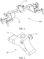
FIG. 1 is a three-dimensional schematic structural diagram of a hub holding apparatus according to an embodiment of the present application; -
FIG. 2 is a three-dimensional schematic structural diagram of a mounting assembly in the hub holding apparatus shown inFIG. 1 ; -
FIG. 3 is an exploded view of the mounting assembly in the hub holding apparatus shown inFIG. 2 ; -
FIG. 4 is a cross-sectional view of the mounting assembly in the hub holding apparatus shown inFIG. 2 ; -
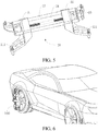
FIG. 5 is a three-dimensional diagram of a bracket in the hub holding apparatus shown inFIG. 1 ; and -
FIG. 6 is a status diagram of the hub holding apparatus shown inFIG. 1 in use. - For ease of understanding this application, this application is described in further detail below with reference to the accompanying drawings and detailed description. It should be noted that an element described as being "fixed" to another element may be directly on the other element, or one or more intervening components may be present. An element described as being "connected" to another element may be directly connected to the other element, or one or more intervening components may be present. As used in the specification, orientation or position relationships indicated by the terms such as "upper", "lower", "inside", "outside" and "bottom" are based on orientation or position relationships shown in the accompanying drawings, and are used only for ease and brevity of illustration and description, rather than indicating or implying that the mentioned apparatus or component needs to have a particular orientation or needs to be constructed and operated in a particular orientation. Therefore, such terms should not be construed as limiting of this application. In addition, the terms such as "first", "second", and "third" are used only for the purpose of description, and should not be understood as indicating or implying relative importance.
- Unless otherwise defined, all technical and scientific terms used herein have the same meaning as commonly understood by one of ordinary skill in the art to which this application belongs. The terms used in the specification of this application are merely used for describing specific embodiments, and are not intended to limit this application. As used herein, the term "and/or" includes any and all combinations of one or more related items listed.
- In addition, the technical features provided in different embodiments of this application to be described below may be combined with each other as long as no conflict occurs.
- Referring to
FIG. 1 to FIG. 3 together, an embodiment of the present application provides ahub holding apparatus 100, including amounting assembly 10 and abracket 20. Themounting assembly 10 is mounted at thebracket 20 and is configured to mount an auxiliary device. - The
mounting assembly 10 includes abase 11, afirst nut 12, asecond nut 13 and ascrew 14. Amounting hole 111 and a receivingcavity 112 are disposed on thebase 11. Themounting hole 111 and thereceiving cavity 112 are both cylindrical. A center line of themounting hole 111 is perpendicular to a center line of thereceiving cavity 112, and themounting hole 111 is in communication with thereceiving cavity 112. Thefirst nut 12 and thesecond nut 13 are sleeved on thescrew 14, and one end of each of thefirst nut 12, thesecond nut 13 and thescrew 14 is received in thereceiving cavity 112. Thescrew 14 is rotatable relative to thebase 11. - Referring to
FIG. 4 , in particular, themounting hole 111 is disposed on a mounting surface of thebase 11 for mounting an auxiliary device. Thereceiving cavity 112 is disposed on thebase 11 and penetrates from one side to the other side of the base 11 (that is, thereceiving cavity 112 is a through hole). Themounting hole 111 and thereceiving cavity 112 are both cylindrical. A center line of themounting hole 111 is perpendicular to a center line of thereceiving cavity 112, and themounting hole 111 is in communication with thereceiving cavity 112. Afixing hole 113 is further disposed on thebase 11. Thefixing hole 113 penetrates from one side of thebase 11 to the other side (that is, thefixing hole 113 is a through hole). - The
first nut 12 has a first thread disposed along a first rotation direction, and thesecond nut 13 has a second thread disposed along a second rotation direction. The first rotation direction and the second rotation direction are opposite to each other. A thread pitch of the first thread is equal to a thread pitch of the second thread. - It may be understood that, in this embodiment, the first rotation direction is a clockwise direction, and the second rotation direction is a counterclockwise direction. In some other embodiments, the first rotation direction is a counterclockwise direction, and the second rotation direction is a clockwise direction.
- It may be understood that, in other embodiments, the
first nut 12 and thesecond nut 13 may be of a same type, which may be mounted at thescrew 14 in opposite directions. - The
screw 14 includes a first threaded portion 141, a second threadedportion 142, a connectingportion 143, and ahandle 144. One end of the first threaded portion 141 is fixedly connected to one end of the second threadedportion 142, another end of the second threadedportion 142 is fixedly connected to one end of the connectingportion 143, and thehandle 144 is fixed to another end of the connectingportion 143. - The first threaded portion 141 and the second threaded
portion 142 are both cylindrical, and both the first threaded portion 141 and the second threadedportion 142 have a thread on outer surfaces thereof. The thread of the first threaded portion 141 is disposed along a first rotation direction, and the thread of the second threadedportion 142 is disposed along a second rotation direction. The first rotation direction and the second rotation direction are opposite to each other. A thread pitch of the thread of the first threaded portion 141 is equal to a thread pitch of the thread and the second threadedportion 142. - The
first nut 12 is sleeved on the first threaded portion 141 of thescrew 14. When thescrew 14 is rotated, thefirst nut 12 may be rotated relative to thescrew 14, and during the rotation, thefirst nut 12 moves along an axial direction of thescrew 14. Thesecond nut 13 is sleeved on the second threadedportion 142 of thescrew 14. When thescrew 14 is rotated, thesecond nut 13 may be rotated relative to thescrew 14, and during the rotation, thesecond nut 13 moves along the axial direction of thescrew 14. Because the threads of the first threaded portion 141 and the second threadedportion 142 rotate in opposite directions and have a same thread pitch, during the rotation of thescrew 14, thefirst nut 12 and thesecond nut 13 approach to or move away from each other. - In this embodiment, when the
screw 14 is rotated along the first rotation direction, thefirst nut 12 and thesecond nut 13 approach to each other; or when thescrew 14 is rotated in the second rotation direction, thefirst nut 12 and thesecond nut 13 move away from each other. When the auxiliary device needs to be mounted at thehub holding apparatus 100, a mounting shaft of the auxiliary device is first inserted into the mountinghole 111, and then thescrew 14 is rotated in the first rotation direction. Because the thread of the first threaded portion 141 and the thread of the second threadedportion 142 have an equal thread pitch, thefirst nut 12 and thesecond nut 13 move in opposite directions by an equal movement distance, so that a pressing force is generated from both thefirst nut 12 and thesecond nut 13 for locking and fixing the mounting shaft of the auxiliary device. - When the auxiliary device needs to be removed from the
hub holding apparatus 100, thescrew 14 is rotated along the second rotation direction, so that thefirst nut 12 and thesecond nut 13 move away from each other. Because the thread of the first threaded portion 141 and the thread of the second threadedportion 142 have an equal thread pitch, thefirst nut 12 and thesecond nut 13 move in opposite directions by an equal movement distance. When thefirst nut 12 and thesecond nut 13 move to a specific position, the pressing force of thefirst nut 12 and thesecond nut 13 on the mounting shaft of the auxiliary device disappears. In this case, the mounting shaft of the auxiliary device may be pulled out from the mountinghole 111 to complete removal. - The mounting
assembly 10 further includes afirst baffle plate 15 and asecond baffle plate 16, thefirst baffle plate 15 being disposed at another end of the first threaded portion 141, and thesecond baffle plate 16 being disposed at the another end of the second threadedportion 142. Thefirst baffle plate 15 and thesecond baffle plate 16 are both used for limiting, and are configured to prevent thefirst nut 12 and thesecond nut 13 from being separated from thescrew 14 during the rotation of thescrew 14. - In this embodiment, a limiting block (not shown) is disposed on each of the
first nut 12 and thesecond nut 13, and a limiting groove (not shown) is disposed on an inner inside surface of the receivingcavity 112. The limiting groove is parallel to the center line of the receivingcavity 112. The limiting block of thefirst nut 12 and the limiting block of thesecond nut 13 are both embedded in the limiting groove and may slide in the limiting groove. The structure is designed to prevent thefirst nut 12 and thesecond nut 13 from rotating with the screw 14 (that is, when thescrew 14 is rotated relative to thebase 11, thefirst nut 12 and thesecond nut 13 do not rotate, but move along the axial direction of the screw 14). - In this embodiment, the limiting block may be a bolt or a screw. A threaded hole is disposed on a side surface of each of the
first nut 12 and thesecond nut 13. One end of the bolt or the screw is screwed into the threaded hole, and another end protrudes from each of thefirst nut 12 and thesecond nut 13 for limiting. - It may be understood that, in other embodiments, the
first nut 12 and thesecond nut 13 may both be hexagon nuts, and a cross-sectional shape of the receivingcavity 112 is a hexagon to prevent thefirst nut 12 and thesecond nut 13 from rotating relative to the base 11 (that is, there is a limiting structure among thefirst nut 12, thesecond nut 13 and the receivingcavity 112 for preventing thefirst nut 12 and thesecond nut 13 from rotating relative to the base 11). - Referring to
FIG. 5 , thebracket 20 includes a first mountingportion 21, a second mountingportion 22, a connectingrod 23, a threadedrod 24, and arotatable handle 25. There are two connectingrods 23, one end of one of the connectingrods 23 being fixedly connected to one end of the other of the connectingrods 23, and another end of one of the connectingrods 23 being fixedly connected to another end of the other of the connectingrods 23. The two connectingrods 23 are parallel to each other. The first mountingportion 21 is sleeved on one end of each of the two connectingrods 23 respectively and is slidable on the two connectingrods 23; and the second mountingportion 22 is sleeved on another end of each of the two connectingrods 23 respectively and is slidable on the two connectingrods 23. A first threaded hole (not shown) is disposed on the first mountingportion 21, and a second threaded hole (not shown) is disposed on the second mountingportion 22. The threadedrod 24 passes through the first threaded hole and second threaded hole respectively. - The rotatable handle 25 is fixed to one end of the threaded
rod 24, and rotating therotating handle 25 may drive the threadedrod 24 to rotate. During the rotation, the first mountingportion 21 and the second mountingportion 22 approach to or move away from each other along the two connectingrods 23. A first engagingpost 211 for engaging a hub is disposed on the first mountingportion 21, and there are two first engagingposts 211 in total. A secondengaging post 221 for engaging a hub is disposed on the second mountingportion 22, and there are two secondengaging posts 221 in total. - Referring to
FIG. 6 , rotating the threadedrod 24 may drive the first mountingportion 21 and the second mountingportion 22 to approach to each other, so that the firstengaging post 211 and the secondengaging post 221 both hold the hub, thereby fixedly connecting thebracket 20 to the hub. - In the
hub holding apparatus 100 in the embodiments of the present application, two nuts (12, 13) are sleeved on ascrew 14, and when thescrew 14 is rotated, the two nuts (12, 13) approach to or move away from each other along thescrew 14. Based on the structure, the auxiliary device is quickly and conveniently mounted at thehub holding apparatus 100, and the auxiliary device is extremely easily removed from thehub holding apparatus 100. - It should be finally noted that the above embodiments are merely intended for describing the technical solutions of this application rather than limiting this application. Based on the idea of this application, the technical features in the foregoing embodiments or different embodiments may be combined, the steps may be implemented in any order, and many other changes in the different aspects of the present invention as described above may exist. For brevity, such changes are not provided in the detailed descriptions. Although this application is described in detail with reference to the foregoing embodiments, those of ordinary skill in the art should understand that they can still make modifications to the technical solutions described in the foregoing embodiments or make equivalent substitutions to some technical features thereof, without departing from scope of the technical solutions of the embodiments of this application.
Claims (10)
- A hub holding apparatus (100), comprising:a base (11) on which a mounting hole (111) and a receiving cavity (112) are disposed, a center line of the mounting hole (111) being perpendicular to a center line of the receiving cavity (112), and the mounting hole (111) being in communication with the receiving cavity (112);a screw (14) rotatable relative to the base (11), the screw (14) comprising a first threaded portion (141) and a second threaded portion (142), one end of the first threaded portion (141) being fixedly connected to one end of the second threaded portion (142), and both the first threaded portion (141) and the second threaded portion (142) being received in the receiving cavity (112), a thread of the first threaded portion (141) being disposed along a first rotation direction, and a thread of the second threaded portion (142) being disposed along a second rotation direction, the first rotation direction and the second rotation direction being opposite to each other;a first nut (12) sleeved on the first threaded portion (141) and received in the receiving cavity (112); anda second nut (13) sleeved on the second threaded portion (142) and received in the receiving cavity (112).
- The hub holding apparatus (100) according to claim 1, wherein
a thread pitch of the thread of the first threaded portion (141) is equal to a thread pitch of the thread of the second threaded portion (142). - The hub holding apparatus (100) according to claim 1, wherein
the first nut (12) has a first thread disposed along the first rotation direction; and
the second nut (13) has a second thread disposed along the second rotation direction. - The hub holding apparatus (100) according to claim 1, wherein
the screw (14) further comprises a connecting portion (143) and a handle (144), another end of the second threaded portion (142) being fixedly connected to one end of the connecting portion (143), and the handle (144) being fixed to another end of the connecting portion (143). - The hub holding apparatus (100) according to claim 4, wherein
the hub holding apparatus (100) further comprises a first baffle plate (15) and a second baffle plate (16), the first baffle plate (15) being disposed at another end of the first threaded portion (141), and the second baffle plate (16) being disposed at the another end of the second threaded portion (142). - The hub holding apparatus (100) according to claim 1, wherein
a limiting block is disposed on each of the first nut (12) and the second nut (13), and a limiting groove is disposed on an inner side surface of the receiving cavity (112), a center line of the limiting groove being parallel to a center line of the receiving cavity (112); and
the limiting block of the first nut (12) and the limiting block of the second nut (13) are both embedded in the limiting groove and are slidable in the limiting groove. - The hub holding apparatus (100) according to claim 1, wherein
the first nut (12) and the second nut (13) are both hexagon nuts, and a cross-sectional shape of the receiving cavity (112) is a hexagon. - The hub holding apparatus (100) according to any of claims 1 to 7, wherein
the hub holding apparatus (100) further comprises a bracket (20), wherein the base (11) is fixed to the bracket (20), and the bracket (20) may be mounted at a hub. - The hub holding apparatus (100) according to claim 8, wherein
the bracket (20) comprises a first mounting portion (21), a second mounting portion (22), a connecting rod (23), and a threaded rod (24); wherein
there are two connecting rods (23), one end of one of the connecting rods (23) being fixedly connected to one end of the other of the connecting rods (23), and another end of one of the connecting rods (23) being fixedly connected to another end of the other of the connecting rods (23);
the first mounting portion (21) is sleeved on one end of each of the two connecting rods respectively (23) and may slide on the two connecting rods (23);
the second mounting portion (22) is sleeved on the another end of each of the two connecting rods (23) respectively and may slide on the two connecting rods (23); and
the threaded rod (24) is rotatably connected to the first mounting portion (21) and the second mounting portion (22). - The hub holding apparatus (100) according to claim 9, wherein
a rotational handle (25) is disposed on one end of the threaded rod (24), wherein rotating the rotational handle (25) may drive the threaded rod (24) to rotate, and during the rotation, the first mounting portion (21) and the second mounting portion (22) approach to or move away from each other along the two connecting rods (23).
Applications Claiming Priority (2)
| Application Number | Priority Date | Filing Date | Title |
|---|---|---|---|
| CN201721154833.9U CN207256067U (en) | 2017-09-08 | 2017-09-08 | Wheel hub clamping device |
| PCT/CN2018/104217 WO2019047864A1 (en) | 2017-09-08 | 2018-09-05 | Hub clamping device |
Publications (2)
| Publication Number | Publication Date |
|---|---|
| EP3680066A1 true EP3680066A1 (en) | 2020-07-15 |
| EP3680066A4 EP3680066A4 (en) | 2021-06-02 |
Family
ID=61920374
Family Applications (1)
| Application Number | Title | Priority Date | Filing Date |
|---|---|---|---|
| EP18854814.3A Withdrawn EP3680066A4 (en) | 2017-09-08 | 2018-09-05 | Hub clamping device |
Country Status (5)
| Country | Link |
|---|---|
| US (1) | US11279010B2 (en) |
| EP (1) | EP3680066A4 (en) |
| CN (1) | CN207256067U (en) |
| DE (1) | DE212018000310U1 (en) |
| WO (1) | WO2019047864A1 (en) |
Families Citing this family (3)
| Publication number | Priority date | Publication date | Assignee | Title |
|---|---|---|---|---|
| CN111174066B (en) * | 2020-01-21 | 2025-01-07 | 深圳市道通科技股份有限公司 | Wheel clamping device |
| CN111571494A (en) * | 2020-06-17 | 2020-08-25 | 深圳市道通科技股份有限公司 | Hub clamping device |
| CN116000854B (en) * | 2022-12-26 | 2025-12-05 | 江西洪都航空工业股份有限公司 | Pallet nut holder |
Family Cites Families (12)
| Publication number | Priority date | Publication date | Assignee | Title |
|---|---|---|---|---|
| US3990666A (en) * | 1975-08-25 | 1976-11-09 | Ammco Tools, Inc. | Wheel clamp |
| US5024001A (en) * | 1988-10-07 | 1991-06-18 | Balco, Incorporated | Wheel alignment rim clamp claw |
| DE8814598U1 (en) * | 1988-11-23 | 1989-02-09 | Groß, Johannes, 8503 Altdorf | Screw piece with threaded piece |
| JP3630261B2 (en) * | 1997-04-17 | 2005-03-16 | 三菱電機株式会社 | Detector mounting structure |
| JPH1137747A (en) * | 1997-07-15 | 1999-02-12 | Alps Electric Co Ltd | Rotation detecting device for multi-rotating body |
| ITRE20010016U1 (en) * | 2001-05-15 | 2002-11-15 | Corghi Spa | SELF-CENTERING DEVICE FOR THE SUPPORT OF HEADS OF CONTROL OF THE STRUCTURE OF THE WHEELS OF VEHICLES IN GENERAL. |
| DE10135281A1 (en) * | 2001-07-19 | 2003-02-06 | David Fischer | Clamping element for flexible clamping of workpieces |
| US7150105B1 (en) * | 2005-01-12 | 2006-12-19 | Honda Motor Co., Ltd. | Adaptor for use in vehicle wheel alignment |
| CN203190961U (en) * | 2012-12-25 | 2013-09-11 | 东风本田汽车有限公司 | A portable electronic measurer of the dip angle of a wheel |
| CN103063186B (en) * | 2012-12-25 | 2016-06-08 | 东风本田汽车有限公司 | Portable electronic camber tester |
| CN203178081U (en) * | 2013-04-21 | 2013-09-04 | 吉林大学 | Split detachable calibration device of vehicle four-wheel aligner |
| CN104226688B (en) * | 2014-09-09 | 2017-01-18 | 北京京诚之星科技开发有限公司 | Rotary table angle adjusting and locking device |
-
2017
- 2017-09-08 CN CN201721154833.9U patent/CN207256067U/en active Active
-
2018
- 2018-09-05 DE DE212018000310.6U patent/DE212018000310U1/en active Active
- 2018-09-05 EP EP18854814.3A patent/EP3680066A4/en not_active Withdrawn
- 2018-09-05 WO PCT/CN2018/104217 patent/WO2019047864A1/en not_active Ceased
-
2020
- 2020-03-09 US US16/812,793 patent/US11279010B2/en active Active
Also Published As
| Publication number | Publication date |
|---|---|
| DE212018000310U1 (en) | 2020-05-15 |
| CN207256067U (en) | 2018-04-20 |
| WO2019047864A1 (en) | 2019-03-14 |
| US11279010B2 (en) | 2022-03-22 |
| US20200346329A1 (en) | 2020-11-05 |
| EP3680066A4 (en) | 2021-06-02 |
Similar Documents
| Publication | Publication Date | Title |
|---|---|---|
| US11279010B2 (en) | Hub holding apparatus | |
| EP3552855B1 (en) | Circumferential lock mechanism, battery locking device, power battery pack and vehicle | |
| US10495949B2 (en) | Gimbal | |
| EP3637394B1 (en) | Module connection structure and led display screen | |
| US11884147B2 (en) | Circumferential locking mechanism and battery locking device comprising same, power battery pack, and vehicle | |
| CN204361400U (en) | One can rosette for lock processed | |
| EP3168521A1 (en) | Limiting device and aircraft using same | |
| EP3610189B1 (en) | Holder for flat, approximately rectangular devices such as tablet computers or smartphones | |
| EP3171041A1 (en) | Output device | |
| JP5193282B2 (en) | Bolts and nuts with detent mechanism | |
| US20140020848A1 (en) | Extendable handle for a tire spoon and method of operation | |
| CN106796768B (en) | LED display | |
| CN109398246A (en) | Vehicle-carrying display screen and automobile | |
| CN213871789U (en) | Display module connecting structure and display screen | |
| EP3532343B1 (en) | Ventilation grid holder for a mobile terminal | |
| CN206617391U (en) | Circumferential locking mechanism, battery locking device, power battery pack and vehicle | |
| US20230417359A1 (en) | Quick connection structure | |
| CN201723553U (en) | Mechanism for preventing screw stem from being screwed out of blind hole screw sleeve | |
| CN214759524U (en) | Hook | |
| US20140301731A1 (en) | Rotation mechanism for camera | |
| CN201173372Y (en) | Middle shaft device of photographic support | |
| CN206536403U (en) | Tailored version trim ring spanner | |
| CN106272250B (en) | Screw screw device | |
| CN206159192U (en) | Detachable metal square tube and cone connecting device | |
| WO2020177270A1 (en) | Anti-dismounting and anti-loosening base structure of shipborne communication terminal |
Legal Events
| Date | Code | Title | Description |
|---|---|---|---|
| STAA | Information on the status of an ep patent application or granted ep patent |
Free format text: STATUS: THE INTERNATIONAL PUBLICATION HAS BEEN MADE |
|
| PUAI | Public reference made under article 153(3) epc to a published international application that has entered the european phase |
Free format text: ORIGINAL CODE: 0009012 |
|
| STAA | Information on the status of an ep patent application or granted ep patent |
Free format text: STATUS: REQUEST FOR EXAMINATION WAS MADE |
|
| 17P | Request for examination filed |
Effective date: 20200323 |
|
| AK | Designated contracting states |
Kind code of ref document: A1 Designated state(s): AL AT BE BG CH CY CZ DE DK EE ES FI FR GB GR HR HU IE IS IT LI LT LU LV MC MK MT NL NO PL PT RO RS SE SI SK SM TR |
|
| AX | Request for extension of the european patent |
Extension state: BA ME |
|
| DAV | Request for validation of the european patent (deleted) | ||
| DAX | Request for extension of the european patent (deleted) | ||
| A4 | Supplementary search report drawn up and despatched |
Effective date: 20210504 |
|
| RIC1 | Information provided on ipc code assigned before grant |
Ipc: B25B 11/00 20060101AFI20210428BHEP Ipc: B25B 1/10 20060101ALI20210428BHEP |
|
| STAA | Information on the status of an ep patent application or granted ep patent |
Free format text: STATUS: THE APPLICATION HAS BEEN WITHDRAWN |
|
| 18W | Application withdrawn |
Effective date: 20211108 |