EP3679899A1 - Glenoidimplantat - Google Patents
Glenoidimplantat Download PDFInfo
- Publication number
- EP3679899A1 EP3679899A1 EP19209370.6A EP19209370A EP3679899A1 EP 3679899 A1 EP3679899 A1 EP 3679899A1 EP 19209370 A EP19209370 A EP 19209370A EP 3679899 A1 EP3679899 A1 EP 3679899A1
- Authority
- EP
- European Patent Office
- Prior art keywords
- glenoid
- base plate
- component
- recessed portion
- implant
- Prior art date
- Legal status (The legal status is an assumption and is not a legal conclusion. Google has not performed a legal analysis and makes no representation as to the accuracy of the status listed.)
- Granted
Links
- 241001653121 Glenoides Species 0.000 title claims abstract description 170
- 239000007943 implant Substances 0.000 title claims abstract description 90
- 210000005065 subchondral bone plate Anatomy 0.000 claims description 27
- 230000002093 peripheral effect Effects 0.000 claims description 23
- 229910052751 metal Inorganic materials 0.000 claims description 8
- 239000002184 metal Substances 0.000 claims description 8
- 238000006243 chemical reaction Methods 0.000 claims 2
- 238000000034 method Methods 0.000 description 20
- 230000008901 benefit Effects 0.000 description 7
- 238000003780 insertion Methods 0.000 description 4
- 230000037431 insertion Effects 0.000 description 4
- 229920000642 polymer Polymers 0.000 description 4
- 239000011359 shock absorbing material Substances 0.000 description 4
- 210000000988 bone and bone Anatomy 0.000 description 3
- 229920001296 polysiloxane Polymers 0.000 description 3
- 229920002635 polyurethane Polymers 0.000 description 3
- 239000004814 polyurethane Substances 0.000 description 3
- 210000000323 shoulder joint Anatomy 0.000 description 3
- 239000004698 Polyethylene Substances 0.000 description 2
- 229910001069 Ti alloy Inorganic materials 0.000 description 2
- 230000000295 complement effect Effects 0.000 description 2
- 230000006835 compression Effects 0.000 description 2
- 238000007906 compression Methods 0.000 description 2
- 229920001577 copolymer Polymers 0.000 description 2
- 210000002758 humerus Anatomy 0.000 description 2
- 238000003801 milling Methods 0.000 description 2
- 238000012986 modification Methods 0.000 description 2
- 230000004048 modification Effects 0.000 description 2
- -1 polyethylene Polymers 0.000 description 2
- 229920000573 polyethylene Polymers 0.000 description 2
- 230000006978 adaptation Effects 0.000 description 1
- 230000002730 additional effect Effects 0.000 description 1
- 230000004075 alteration Effects 0.000 description 1
- 238000013459 approach Methods 0.000 description 1
- 238000011882 arthroplasty Methods 0.000 description 1
- 230000006870 function Effects 0.000 description 1
- 238000002513 implantation Methods 0.000 description 1
- 230000003993 interaction Effects 0.000 description 1
- 230000008569 process Effects 0.000 description 1
- 210000001991 scapula Anatomy 0.000 description 1
- 229920002994 synthetic fiber Polymers 0.000 description 1
Images


Classifications
-
- A—HUMAN NECESSITIES
- A61—MEDICAL OR VETERINARY SCIENCE; HYGIENE
- A61F—FILTERS IMPLANTABLE INTO BLOOD VESSELS; PROSTHESES; DEVICES PROVIDING PATENCY TO, OR PREVENTING COLLAPSING OF, TUBULAR STRUCTURES OF THE BODY, e.g. STENTS; ORTHOPAEDIC, NURSING OR CONTRACEPTIVE DEVICES; FOMENTATION; TREATMENT OR PROTECTION OF EYES OR EARS; BANDAGES, DRESSINGS OR ABSORBENT PADS; FIRST-AID KITS
- A61F2/00—Filters implantable into blood vessels; Prostheses, i.e. artificial substitutes or replacements for parts of the body; Appliances for connecting them with the body; Devices providing patency to, or preventing collapsing of, tubular structures of the body, e.g. stents
- A61F2/02—Prostheses implantable into the body
- A61F2/30—Joints
- A61F2/40—Joints for shoulders
- A61F2/4081—Glenoid components, e.g. cups
-
- A—HUMAN NECESSITIES
- A61—MEDICAL OR VETERINARY SCIENCE; HYGIENE
- A61F—FILTERS IMPLANTABLE INTO BLOOD VESSELS; PROSTHESES; DEVICES PROVIDING PATENCY TO, OR PREVENTING COLLAPSING OF, TUBULAR STRUCTURES OF THE BODY, e.g. STENTS; ORTHOPAEDIC, NURSING OR CONTRACEPTIVE DEVICES; FOMENTATION; TREATMENT OR PROTECTION OF EYES OR EARS; BANDAGES, DRESSINGS OR ABSORBENT PADS; FIRST-AID KITS
- A61F2/00—Filters implantable into blood vessels; Prostheses, i.e. artificial substitutes or replacements for parts of the body; Appliances for connecting them with the body; Devices providing patency to, or preventing collapsing of, tubular structures of the body, e.g. stents
- A61F2/02—Prostheses implantable into the body
- A61F2/30—Joints
- A61F2002/30001—Additional features of subject-matter classified in A61F2/28, A61F2/30 and subgroups thereof
- A61F2002/30316—The prosthesis having different structural features at different locations within the same prosthesis; Connections between prosthetic parts; Special structural features of bone or joint prostheses not otherwise provided for
- A61F2002/30329—Connections or couplings between prosthetic parts, e.g. between modular parts; Connecting elements
- A61F2002/30331—Connections or couplings between prosthetic parts, e.g. between modular parts; Connecting elements made by longitudinally pushing a protrusion into a complementarily-shaped recess, e.g. held by friction fit
- A61F2002/30362—Connections or couplings between prosthetic parts, e.g. between modular parts; Connecting elements made by longitudinally pushing a protrusion into a complementarily-shaped recess, e.g. held by friction fit with possibility of relative movement between the protrusion and the recess
-
- A—HUMAN NECESSITIES
- A61—MEDICAL OR VETERINARY SCIENCE; HYGIENE
- A61F—FILTERS IMPLANTABLE INTO BLOOD VESSELS; PROSTHESES; DEVICES PROVIDING PATENCY TO, OR PREVENTING COLLAPSING OF, TUBULAR STRUCTURES OF THE BODY, e.g. STENTS; ORTHOPAEDIC, NURSING OR CONTRACEPTIVE DEVICES; FOMENTATION; TREATMENT OR PROTECTION OF EYES OR EARS; BANDAGES, DRESSINGS OR ABSORBENT PADS; FIRST-AID KITS
- A61F2/00—Filters implantable into blood vessels; Prostheses, i.e. artificial substitutes or replacements for parts of the body; Appliances for connecting them with the body; Devices providing patency to, or preventing collapsing of, tubular structures of the body, e.g. stents
- A61F2/02—Prostheses implantable into the body
- A61F2/30—Joints
- A61F2002/30001—Additional features of subject-matter classified in A61F2/28, A61F2/30 and subgroups thereof
- A61F2002/30316—The prosthesis having different structural features at different locations within the same prosthesis; Connections between prosthetic parts; Special structural features of bone or joint prostheses not otherwise provided for
- A61F2002/30329—Connections or couplings between prosthetic parts, e.g. between modular parts; Connecting elements
- A61F2002/30476—Connections or couplings between prosthetic parts, e.g. between modular parts; Connecting elements locked by an additional locking mechanism
- A61F2002/30487—Circumferential cooperating grooves and beads on cooperating lateral surfaces of a mainly longitudinal connection
-
- A—HUMAN NECESSITIES
- A61—MEDICAL OR VETERINARY SCIENCE; HYGIENE
- A61F—FILTERS IMPLANTABLE INTO BLOOD VESSELS; PROSTHESES; DEVICES PROVIDING PATENCY TO, OR PREVENTING COLLAPSING OF, TUBULAR STRUCTURES OF THE BODY, e.g. STENTS; ORTHOPAEDIC, NURSING OR CONTRACEPTIVE DEVICES; FOMENTATION; TREATMENT OR PROTECTION OF EYES OR EARS; BANDAGES, DRESSINGS OR ABSORBENT PADS; FIRST-AID KITS
- A61F2/00—Filters implantable into blood vessels; Prostheses, i.e. artificial substitutes or replacements for parts of the body; Appliances for connecting them with the body; Devices providing patency to, or preventing collapsing of, tubular structures of the body, e.g. stents
- A61F2/02—Prostheses implantable into the body
- A61F2/30—Joints
- A61F2002/30001—Additional features of subject-matter classified in A61F2/28, A61F2/30 and subgroups thereof
- A61F2002/30316—The prosthesis having different structural features at different locations within the same prosthesis; Connections between prosthetic parts; Special structural features of bone or joint prostheses not otherwise provided for
- A61F2002/30535—Special structural features of bone or joint prostheses not otherwise provided for
- A61F2002/30563—Special structural features of bone or joint prostheses not otherwise provided for having elastic means or damping means, different from springs, e.g. including an elastomeric core or shock absorbers
-
- A—HUMAN NECESSITIES
- A61—MEDICAL OR VETERINARY SCIENCE; HYGIENE
- A61F—FILTERS IMPLANTABLE INTO BLOOD VESSELS; PROSTHESES; DEVICES PROVIDING PATENCY TO, OR PREVENTING COLLAPSING OF, TUBULAR STRUCTURES OF THE BODY, e.g. STENTS; ORTHOPAEDIC, NURSING OR CONTRACEPTIVE DEVICES; FOMENTATION; TREATMENT OR PROTECTION OF EYES OR EARS; BANDAGES, DRESSINGS OR ABSORBENT PADS; FIRST-AID KITS
- A61F2/00—Filters implantable into blood vessels; Prostheses, i.e. artificial substitutes or replacements for parts of the body; Appliances for connecting them with the body; Devices providing patency to, or preventing collapsing of, tubular structures of the body, e.g. stents
- A61F2/02—Prostheses implantable into the body
- A61F2/30—Joints
- A61F2002/30001—Additional features of subject-matter classified in A61F2/28, A61F2/30 and subgroups thereof
- A61F2002/30316—The prosthesis having different structural features at different locations within the same prosthesis; Connections between prosthetic parts; Special structural features of bone or joint prostheses not otherwise provided for
- A61F2002/30535—Special structural features of bone or joint prostheses not otherwise provided for
- A61F2002/30565—Special structural features of bone or joint prostheses not otherwise provided for having spring elements
-
- A—HUMAN NECESSITIES
- A61—MEDICAL OR VETERINARY SCIENCE; HYGIENE
- A61F—FILTERS IMPLANTABLE INTO BLOOD VESSELS; PROSTHESES; DEVICES PROVIDING PATENCY TO, OR PREVENTING COLLAPSING OF, TUBULAR STRUCTURES OF THE BODY, e.g. STENTS; ORTHOPAEDIC, NURSING OR CONTRACEPTIVE DEVICES; FOMENTATION; TREATMENT OR PROTECTION OF EYES OR EARS; BANDAGES, DRESSINGS OR ABSORBENT PADS; FIRST-AID KITS
- A61F2/00—Filters implantable into blood vessels; Prostheses, i.e. artificial substitutes or replacements for parts of the body; Appliances for connecting them with the body; Devices providing patency to, or preventing collapsing of, tubular structures of the body, e.g. stents
- A61F2/02—Prostheses implantable into the body
- A61F2/30—Joints
- A61F2/30767—Special external or bone-contacting surface, e.g. coating for improving bone ingrowth
- A61F2/30771—Special external or bone-contacting surface, e.g. coating for improving bone ingrowth applied in original prostheses, e.g. holes or grooves
- A61F2002/30772—Apertures or holes, e.g. of circular cross section
- A61F2002/30774—Apertures or holes, e.g. of circular cross section internally-threaded
-
- A—HUMAN NECESSITIES
- A61—MEDICAL OR VETERINARY SCIENCE; HYGIENE
- A61F—FILTERS IMPLANTABLE INTO BLOOD VESSELS; PROSTHESES; DEVICES PROVIDING PATENCY TO, OR PREVENTING COLLAPSING OF, TUBULAR STRUCTURES OF THE BODY, e.g. STENTS; ORTHOPAEDIC, NURSING OR CONTRACEPTIVE DEVICES; FOMENTATION; TREATMENT OR PROTECTION OF EYES OR EARS; BANDAGES, DRESSINGS OR ABSORBENT PADS; FIRST-AID KITS
- A61F2/00—Filters implantable into blood vessels; Prostheses, i.e. artificial substitutes or replacements for parts of the body; Appliances for connecting them with the body; Devices providing patency to, or preventing collapsing of, tubular structures of the body, e.g. stents
- A61F2/02—Prostheses implantable into the body
- A61F2/30—Joints
- A61F2/30767—Special external or bone-contacting surface, e.g. coating for improving bone ingrowth
- A61F2/30771—Special external or bone-contacting surface, e.g. coating for improving bone ingrowth applied in original prostheses, e.g. holes or grooves
- A61F2002/30878—Special external or bone-contacting surface, e.g. coating for improving bone ingrowth applied in original prostheses, e.g. holes or grooves with non-sharp protrusions, for instance contacting the bone for anchoring, e.g. keels, pegs, pins, posts, shanks, stems, struts
-
- A—HUMAN NECESSITIES
- A61—MEDICAL OR VETERINARY SCIENCE; HYGIENE
- A61F—FILTERS IMPLANTABLE INTO BLOOD VESSELS; PROSTHESES; DEVICES PROVIDING PATENCY TO, OR PREVENTING COLLAPSING OF, TUBULAR STRUCTURES OF THE BODY, e.g. STENTS; ORTHOPAEDIC, NURSING OR CONTRACEPTIVE DEVICES; FOMENTATION; TREATMENT OR PROTECTION OF EYES OR EARS; BANDAGES, DRESSINGS OR ABSORBENT PADS; FIRST-AID KITS
- A61F2/00—Filters implantable into blood vessels; Prostheses, i.e. artificial substitutes or replacements for parts of the body; Appliances for connecting them with the body; Devices providing patency to, or preventing collapsing of, tubular structures of the body, e.g. stents
- A61F2/02—Prostheses implantable into the body
- A61F2/30—Joints
- A61F2/40—Joints for shoulders
- A61F2/4014—Humeral heads or necks; Connections of endoprosthetic heads or necks to endoprosthetic humeral shafts
- A61F2002/4018—Heads or epiphyseal parts of humerus
- A61F2002/4022—Heads or epiphyseal parts of humerus having a concave shape, e.g. hemispherical cups
-
- A—HUMAN NECESSITIES
- A61—MEDICAL OR VETERINARY SCIENCE; HYGIENE
- A61F—FILTERS IMPLANTABLE INTO BLOOD VESSELS; PROSTHESES; DEVICES PROVIDING PATENCY TO, OR PREVENTING COLLAPSING OF, TUBULAR STRUCTURES OF THE BODY, e.g. STENTS; ORTHOPAEDIC, NURSING OR CONTRACEPTIVE DEVICES; FOMENTATION; TREATMENT OR PROTECTION OF EYES OR EARS; BANDAGES, DRESSINGS OR ABSORBENT PADS; FIRST-AID KITS
- A61F2/00—Filters implantable into blood vessels; Prostheses, i.e. artificial substitutes or replacements for parts of the body; Appliances for connecting them with the body; Devices providing patency to, or preventing collapsing of, tubular structures of the body, e.g. stents
- A61F2/02—Prostheses implantable into the body
- A61F2/30—Joints
- A61F2/40—Joints for shoulders
- A61F2/4081—Glenoid components, e.g. cups
- A61F2002/4085—Glenoid components, e.g. cups having a convex shape, e.g. hemispherical heads
-
- A—HUMAN NECESSITIES
- A61—MEDICAL OR VETERINARY SCIENCE; HYGIENE
- A61F—FILTERS IMPLANTABLE INTO BLOOD VESSELS; PROSTHESES; DEVICES PROVIDING PATENCY TO, OR PREVENTING COLLAPSING OF, TUBULAR STRUCTURES OF THE BODY, e.g. STENTS; ORTHOPAEDIC, NURSING OR CONTRACEPTIVE DEVICES; FOMENTATION; TREATMENT OR PROTECTION OF EYES OR EARS; BANDAGES, DRESSINGS OR ABSORBENT PADS; FIRST-AID KITS
- A61F2220/00—Fixations or connections for prostheses classified in groups A61F2/00 - A61F2/26 or A61F2/82 or A61F9/00 or A61F11/00 or subgroups thereof
- A61F2220/0008—Fixation appliances for connecting prostheses to the body
Definitions
- the present disclosure relates to an invention.
- the head of the humerus interacts with the glenoid cavity of the scapula in a manner similar to a "ball and socket" joint. Over time, it may become necessary to replace the shoulder joint with a prosthetic shoulder joint including a glenoid implant.
- the glenoid implant typically includes an articular component that is adapted to articulate with the head of a humeral component, for example, the anatomical head of the humerus or a portion of a humeral implant.
- the glenoid implant may provide an anatomical configuration in which the articular component includes a cavity that replaces the glenoid cavity.
- the glenoid implant may provide a reversed configuration in which the articular component includes a hemispherical dome that cooperates with a complementary cavity defined by a humeral implant.
- Some glenoid implants can include a base plate for fixing the articular body to the glenoid.
- the base plate can be permanently secured in the glenoid by the surgeon before an articular component is positioned on the base plate.
- the glenoid implant needs to be replaced.
- the base plate remains coupled to the glenoid and the articular body is replaced.
- the surgeon may provide a new articular component of a different configuration.
- the implant may be converted from an anatomical configuration to a reversed configuration.
- the combination of the base plate and the articular component e.g., a glenoid component or a reverse component
- the articular component can be too thick and further displace the glenoid from the humeral component.
- a base plate can be at least partially loaded into the glenoid, such that a distal facing surface of the base plate is positioned in the glenoid and beyond the subchondral bone.
- milling the glenoid to insert the base plate can be difficult and require removal of a large portion of the bone.
- loading the glenoid implant into the glenoid leaves no subchondral bone support behind the base plate. Since there is no subchondral support behind the glenoid implant, surgeons cannot lag screws to achieve the desired compression and the glenoid implant can subside.
- the base plate may include metal, such as a titanium alloy, while the articular body can include a synthetic material, such as polyethylene.
- the direct interaction between the metal base plate and synthetic articular body can cause the synthetic articular body to wear and displace the articular surface of the glenoid component.
- a proximal surface of the base plate may be spaced apart from a distal facing surface of the articular component when the articular component is coupled to the base plate.
- a glenoid implant including a base plate and an articular component configured to removably couple to the base plate.
- the base plate can include a body and a support structure extending from a distal surface of the body.
- the body can include a plurality of openings.
- the articular component can include a recessed portion configured to at least partially receive the body of the base plate.
- At least one engagement structure can protrude from a distal facing surface of the recessed portion. Each engagement structure can correspond to one of the plurality of openings in the body.
- a proximal surface of the base plate can be spaced apart from the distal facing surface of the recessed portion when the articular component is coupled to the base plate, and/or a distal face of the articular component surrounding the recessed portion can be configured to abut the subchondral bone.
- the method can include inserting a base plate into a glenoid cavity such that a support structure of the base plate is inserted into a subchondral bone portion and a body of the base plate is positioned thereon a subchondral bone surface.
- the body can include a plurality of openings.
- a screw can be advanced through one of the plurality of openings and into the subchondral bone.
- a first articular component can be secured to the base plate such that a recessed portion of the first articular component is advanced over the body of the base plate and an engagement member of the first articular component is inserted into a corresponding opening of the plurality of openings.
- the above-mentioned method can further include removing the first articular component from the base plate and securing a second articular component to the base plate.
- the first articular component can be a glenoid component and the second articular component can be a reverse component.
- a glenoid system including a base plate, a glenoid component, and a reverse component.
- the base plate can include a body and a support structure extending from a distal surface of the body.
- the body can include a plurality of openings.
- the glenoid component can be configured to removably couple to the base plate and can include a recessed portion configured to at least partially receive the body of the base plate.
- a proximal surface of the base plate can be spaced apart from a distal facing surface of the anatomical recessed portion when the glenoid component is coupled to the base plate.
- the reverse component can be configured to removably couple to the base plate and can include a reverse recessed portion configured to at least partially receive the body of the base plate.
- the proximal surface of the base plate can be spaced apart from a distal facing surface of the reverse recessed portion when the reverse component is coupled to the base plate.
- Some glenoid implants can include a base component for fixing the articular body to the glenoid.
- the base component can be permanently secured in the glenoid by the surgeon, for example by using screws, before an articular component is positioned on the base plate.
- the glenoid implant needs to be replaced.
- the base component remains coupled to the glenoid and the articular body is replaced.
- the surgeon may provide a new articular component of a different configuration.
- the implant may be converted from an anatomical configuration to a reversed configuration.
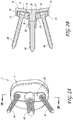
- Figure 1 illustrates one such example of a glenoid component 1100 having a metal body 1105 and a metal base plate 900.
- the body 1105 defines circumferential recess 1107, which extends from the medial side 1102 towards the lateral side 1104.
- the tapered trunnion 1106 extends from the base 1109 of recess 1107 towards the medial side 1102, tapers from base 1009 to its proximal end, and is adapted to be received and attached to the tapered cavity 910 of the baseplate 900.
- Recess 1107 is adapted to receive a portion, or the entirety of, the body 902 of the baseplate 900.
- FIGs 2A-2F illustrate glenoid implants 2, 1002 that can been implanted in a glenoid.
- Each of the glenoid implants 2, 1002 can include an articular component (e.g., a glenoid component 6 or a reverse component 40) removably secured to a base plate 20.
- the glenoid implant 2 can include a glenoid component 6 configured to be removably coupled to the base plate 20 (see Figures 2A and 2B ).
- the base plate 20 can include a body 26 and a support structure 30.
- the body 26 can include an outer peripheral wall 22 having generally curved and/or flat surfaces.
- the outer peripheral wall 22 can extend between a lateral surface 27 (or proximal face) and a medial surface 29 (or distal face) of the body 26 (see Figure 2C ).
- a thickness of the body 26 can be defined from the lateral surface 27 to the medial surface 29 of the body 26.
- a length L 1 of the body 26 can be defined from a superior edge 23 of the body 26 to an inferior edge 25 of the body 26 (see Figure 2C ) and extend along an axis generally perpendicular to a longitudinal axis of the glenoid implant 2 when the implant 2 is secured to the glenoid (see Figures 3A and 3B ).
- a width W 1 of the body 26 can be measured perpendicular to the length L 1 .
- the body 26 can be generally elongate.
- the body 26 can be generally rectangular, generally elliptical, or any other elongate shape.
- a length L 1 of the body 26 can be substantially longer than a width W 1 of the body 26, e.g., the length L 1 can be at least about three times longer than the width W 1 , at least about four times longer than the width W 1 , or more (see Figure 2C ).
- the body 26 can include a plurality of openings 32 (e.g., two, three, four, five, or more). At least some or all of the plurality of openings 32 can be aligned along the length L 1 of the body 26. For example, as shown in Figure 2C , the body 26 can include three openings 32a, 32b, 32c aligned along the length L 1 of the body 26. One or more of the openings 32 may be threaded on an internal wall thereof and adapted to engage a screw 60 (e.g., having a single lead, double lead, triple lead, or other number of leads and/or right or left-handed threads).
- a screw 60 e.g., having a single lead, double lead, triple lead, or other number of leads and/or right or left-handed threads.
- the support structure 30 can extend from the medial surface 29 of the body 26 and extend generally perpendicular to the body 26 (see Figure 2C ).
- the support structure 30 can include a circumferential wall portion extending from a proximal portion 30a to a distal portion 30b of the support structure 30.
- the wall portion can include an exterior surface 31a and an interior surface 31b defining a lumen extending through the support structure 30.
- the exterior surface 31a can be generally smooth and without any threads, ribs, grooves, or other structures.
- the interior surface 31b can be threaded and adapted to engage a screw 60 and/or an engagement structure 18 of the glenoid component 6.
- the lumen of the support structure 30 can be aligned with one of the openings 32.
- the opening 32b aligned with the lumen of the support structure 30 can have a larger diameter than the peripheral openings 32a, 32c. Accordingly, a larger screw 60 can be advanced through the support structure opening 32b than the peripheral openings 32a, 32c.
- the support structure 30 can taper from the proximal portion 30a toward the distal portion 30b.
- the support structure 30 can be generally frustoconical and/or include a chamfer edge at the distal portion 30b of the support structure 30.
- the support structure 30 can be generally cylindrical and include a generally uniform diameter.
- Figure 2C also illustrates an embodiment of the glenoid component 6 adapted to engage the base plate 20.
- the glenoid component 6 can include a lateral surface 16 (or proximal face) and a medial surface 10 (or distal face).
- the medial surface 10 can have a recessed portion 8 with a peripheral wall 14 and a medial-facing surface 12 (or distal-facing surface).
- the recessed portion 8 can be shaped and sized to receive at least a partial thickness of the body 26. More particularly, when assembled, the lateral surface 27 of the base plate 8 can be positioned adjacent to and spaced away from the medial-facing surface 12 of the recessed portion 8.
- the recessed portion 8 can have generally the same shape as the body 26 such that the recessed portion can at least partially or entirely receive the body 26 therein.
- the recessed portion 8 can have a generally elongate shape.
- a length L 2 of the recessed portion 8 can be substantially longer than a width W 2 of the body 26, e.g., the length L 2 can be at least about three times longer than the width W 2 , at least about four times longer than the width W 2 , or more.
- the shape of the recessed portion 8 is complementary to the body 26, such that the recessed portion is shaped to receive the body 26 therein.
- the recessed portion 8 can be centrally located with respect to the glenoid component 6.
- the length L 2 and/or width W 2 of the recessed portion 8 can be greater than the length L 1 and/or width W 1 of the body 26, respectively (see Figure 2C ), such that a space remains between the peripheral walls 14 of the recessed portion 8 and the outer peripheral wall 22 of the body 26 when the glenoid implant 2 is fully assembled (see Figure 2B ).
- a thickness of the peripheral wall 14 of the recessed portion 8 can be greater than a thickness of the peripheral wall 22 the body 26, such that when the glenoid implant 2 is fully assembled, a space remains between the lateral surface 27 of the body 26 and the medial-facing surface 12 of the recessed portion 8.
- the medial surface 29 of the body 26 can be aligned or flush with the medial surface 10 of the glenoid component 6.
- the spacing between the recessed portion 8 and the body 26 can prevent wear between the glenoid component 6 and the base plate 20, particularly when the base plate 20 comprises a metal (e.g., a titanium alloy) and when the glenoid component 6 comprises a polymer (e.g., polyethylene).
- the space between the recessed portion 8 and the body 26 can be filled with a shock absorbing material, such as polymers and copolymers, including, but not limited to silicones and polyurethanes.
- At least one engagement structure 18 can extend from the medial-facing surface 12 of the recessed portion 8 and extend generally perpendicular to the length L 2 of the recessed portion 8.
- Each engagement structure 18 can be a peg, a barb, a screw, or other protruding structure, configured to be received by one of the openings 32 of the body 26 by a screw fit, snap fit, interference fit, or otherwise.
- the glenoid component 6 can include a single engagement structure 18 configured to interface with the opening 32b and/or the support structure 30.
- Each engagement structure 18 can include an outer wall portion that can be threaded to threadably engage of the openings 32.
- the outer wall portion can extend from a proximal portion 19a to a distal portion 19b of the engagement structure 18.
- a length of the engagement structure 18 can be greater than a thickness of the recessed portion 8, such that the distal portion 19b of the engagement structure 18 extends distally of the medial surface 10 of the glenoid component 6.
- the distal portion 19b of the engagement structure 18 can be tapered to facilitate insertion of the engagement structure 18 into one of the openings 32 and/or the support structure 30.
- a reverse component 40 can interface with the base plate 20 shown in Figures 2A-2C to form the glenoid implant 1002.
- the reverse component 40 can include a medial surface 46 (or distal surface) and an articulating surface 44 configured to interface with a portion of a humeral component.
- the medial surface 46 can include a recessed portion 42 having a peripheral wall 50 and a medial-facing surface 52 (or distal-facing surface).
- the recessed portion 42 can be eccentric with respect to the reverse component 40.
- the recessed portion 42 can be closer to an inferior anatomic edge of the reverse component 40 than to a superior anatomic edge of the reverse component 40.
- the reverse component 40 can be placed more inferior on the glenoid surface than the glenoid component 6 to prevent scapular notching.
- the medial surface 46 of the reverse component 40 can be curved to fit the curve of the glenoid.
- the recessed portion 42 can be shaped and sized to receive at least a partial thickness of the body 26.
- the recessed portion 42 can have a generally elongate shape.
- a L 3 of the recessed portion 42 can be substantially longer than a width W 3 of the body 26, e.g., the length L 3 can be at least about three times longer than the width W 3 , at least about four times longer than the width W 3 , or more.
- a width W 4 of a section of the recessed portion 42 surrounding the engagement structure 48 can be greater than the width W3 at another section of the recessed portion 42.
- a thickness of the recessed portion 42 surrounding the engagement structure 48 can be greater than a thickness of the recessed portion 42 at other sections of the recessed portion 42.
- the recessed portion 42 can be larger than the body 26, such a space remains between the recessed portion 8 and the body 26 when the implant 1002 is fully assembled (see Figure 2E ).
- the lateral surface 27 of the body 26 can be spaced apart from the medial-facing surface 52 of the recessed portion 42 and/or the peripheral walls 22 of the body 26 can be spaced apart from the peripheral walls 50 of the recessed portion 42.
- the medial surface 29 of the body 26 can be aligned or flush with the medial surface 46 of the reverse component 40 (See Figure 2E ).
- the space between the recessed portion 8 and the body 26 can be filled with a shock absorbing material, such as polymers and copolymers, including but not limited to silicone and polyurethane.
- At least one engagement structure 48 can protrude from the medial-facing surface 52 of the recessed portion 42 and extend generally perpendicular to the length L 3 of the recessed portion 42.
- Each engagement structure 48 can be a peg, a barb, a screw, or other protruding structure, configured to be received by one of the openings 32 by a screw fit, snap fit, interference fit or otherwise.
- the reverse component 40 can include a single, engagement structure 48 configured to interface with the opening 32b and/or the support structure 30.
- Each engagement structure 48 can include an outer wall portion that can be threaded to threadably engage of the openings 32.
- the outer wall portion can extend from a proximal portion 48a to a distal portion 48b of the engagement structure 48.
- a length of the engagement structure 48 can be greater than a thickness of the recessed portion 42, such that the distal portion 48b of the engagement structure 48 extends distally of the medial surface 46 of the reverse component 40.
- the distal portion 48b of each engagement structure 18 can be tapered to facilitate insertion of the engagement structure 18 into one of the openings 32 and/or the support structure 30.
- FIGs 3A-3C illustrate the glenoid implant 2 secured to the glenoid G.
- the base plate 20 can be secured to the glenoid G with the length of the body 26 extending in a superior-inferior direction.
- the glenoid component 6 can be secured over the base plate 20 (see Figure 3B ).
- a peripheral edge of the glenoid component 6 can form an entire peripheral edge of the glenoid implant 2.
- the entire peripheral edge exterior to the glenoid G (e.g., from the lateral surface 16 to the medial surface 10 of the glenoid implant) can be the glenoid component 6 wherein the base plate 20 is captured between the glenoid component 6 and the glenoid G.
- the medial surface 29 of the body 26 can be substantially flush with the medial surface 10 of the glenoid component 6 when the glenoid implant 2 is assembled.
- the medial surface 10 of the glenoid component 6 and the medial surface 29 of the body 26 can be configured to abut the subchondral bone S. That is to say, at least a portion of each of the medial surface 10 of the glenoid component 6 and the medial surface 29 of the body 26 are in direct contact with the subchondral bone S.
- the medial surface 29 of the body 26 When the medial surface 29 of the body 26 is positioned on the subchondral bone S, a surgeon can lag one or more screws 60 into the subchondral bone S to achieve the desired compression and fix the base plate 20 to the glenoid G. Additionally, since the medial surface 29 of the body can be positioned on the subchondral bone S, it is unnecessary to mill or ream the glenoid G before inserting the glenoid implant 2.
- Figure 3D illustrates a perspective view of the glenoid implant 1002 secured to the glenoid G for use in a reverse shoulder arthroplasty.
- the glenoid implant 1002 includes the reverse component 40, baseplate 20, and screws 60.
- the reverse component 40 can be secured to the same base plate 20 shown in Figures 3A-3C .
- the medial surface 46 of the reverse component 40 can be configured to abut the subchondral bone S.
- Figures 4A-4E illustrate additional embodiments of the glenoid components.
- the glenoid components resemble or are identical to the glenoid components discussed above except as described below. Accordingly, numerals used to identify features of the glenoid components shown in Figures 2A-2E are incremented by a factor of one hundred (100) to identify like features of the glenoid components shown in Figures 4A-4E . Any component or step disclosed in any embodiment in this specification can be used in other embodiments.
- the glenoid component 106 can include a plurality of engagement structures 118 (e.g., two, three, four, five, or more engagement structures). Each engagement structure 118 can be similar to the engagement structure 18 described above. The number of the engagement structures 118 can be the same as the number of openings 132 in the base plate 120. At least some of the engagement structures 118 can be aligned along a transverse axis of the glenoid component 106.
- the glenoid component 106 can include three engagement structures 118a, 118b, 118c aligned along the length of the recessed portion 108.
- Each engagement structure 118a, 118b, 118c can interface with the respective corresponding opening 132a, 132b, 132c.
- the central engagement structure 118b can be longer than the peripheral engagement structures 118a, 118c.
- the base plate 120 can include a plurality of support structures 130a, 130b, 130c extending from the medial surface 129 of the body 126.
- Each of the support structures 130a, 130b, 130c can include features similar to the support structure 30 described above and be aligned with one of the openings 132a, 132b, 132c.
- Each support structure 130a, 130b, 130c can be configured to receive a corresponding engagement structure 118a, 118b, 118c.
- a length of the support structures 130a, 130b, 130c can be sufficient to accommodate a proximal portion of a screw 160 and the corresponding engagement structure 118a, 118b, 118c (see Figure 4A ).
- a central support structure 130b can be longer than peripheral support structures 130a, 130c
- Figure 4D illustrates a reverse component 140 that can interface with the base plate 120 shown in Figure 4C .
- the reverse component 140 can include a single engagement structure 148.
- the reverse component 140 can include a plurality of engagement structures 148 (e.g., two, three, four, five, or more engagement structures).
- the number of engagement structures 148 can correspond to the number of openings 132 in the base plate 120.
- At least some of the engagement structures 148 can be aligned along a transverse axis of the reverse component 140.
- the reverse component 140 can include three engagement structure 148 aligned along the transverse axis of the reverse component 140.
- Figures 5A-5F illustrate additional embodiments of the glenoid components.
- the glenoid components resemble or are identical to the glenoid components discussed above in many respects. Accordingly, numerals used to identify features of the glenoid components shown in Figures 4A-4E are incremented by a factor of 100 hundred (100) to identify like features of the glenoid components shown in Figures 5A-5F . This numbering convention generally applies to the remainder of the figures. Any component or step disclosed in any embodiment in this specification can be used in other embodiments.
- the glenoid component 206 can include a plurality of engagement structures 218 (e.g., two, three, four, five, or more engagement structures). Each engagement structure 218 can be similar to the engagement structure 18 described above.
- the number of engagement structures 218 can be the same as the number of openings 232 in the base plate 220 (see Figures 5E ).
- At least some of the engagement structures 218 can be aligned along a transverse axis of the glenoid component 206.
- at least three engagement structures 218a, 218b, 218c can be aligned along the transverse axis of the glenoid component 206.
- Additional engagement structures 218d, 218e can be laterally displaced from the aligned engagement structures 218a, 218b, 218c and/or from a central transverse axis A (see Figure 5B ).
- the laterally displaced engagement structures 218d, 218e can be positioned such that the arrangement of engagement structures 218 is symmetrical about an axis extending through the aligned engagement structures 218a, 218b, 218c.
- the laterally displaced engagement structures 218d, 218e can be offset from the aligned engagement structures 218a, 218b 218c, for example, the laterally displaced engagement structures 218d, 218e can be positioned between the engagement structures 218b, 218c.
- the base plate 220 can include laterally displaced openings 232d, 232e to accommodate the laterally displaced engagement structures 218d, 218e.
- the base plate 220 can include three openings 232a, 232b, 232c aligned along the transverse axis of the base plate 220 and two openings 232d, 232e displaced from the aligned openings 232a, 232b, 232c.
- the laterally displaced openings 232d, 232e can be positioned such that the arrangement of openings 232 is symmetrical about the aligned openings 232a, 232b, 232c.
- the laterally displaced openings 232d, 232e can be offset from the aligned openings 232a, 232b, 232c, for example, the laterally displaced openings 232d, 232e can be positioned between the engagement structures 232b, 232c.
- the base plate 220 can include a plurality of support structures 230a, 230b, 230c extending from the medial surface 229 of the body 226.
- Each of the support structures 230a, 230b, 230c can include features similar to the support structure 30 described above and can be aligned with one of the openings 232. At least some of the openings 232 can provide access to a corresponding support structure 230a, 230b, 230c.
- the support structures 230a, 230b, 230c can extend from the aligned openings 232a, 232b, 232c, but not the laterally displaced openings 232d, 232e.
- the number of support structures can be the same as the number of openings.
- Figure 5E illustrates a reverse component 240 that can interface with the base plate 220 shown in Figure 5C .
- the reverse component 240 can include a recessed portion 242 that can be sized to accommodate the base plate 230, including the laterally displaced openings 218e, 218d.
- the reverse component 240 can include a single engagement structure 248 similar to engagement structure 48.
- the reverse component 240 can include a plurality of engagement structures 248 (e.g., two, three, four, five, or more engagement structures).
- the number of engagement structures 248 can correspond to the number of openings 232 and/or support structures 230a, 230b, 230c in the base plate 220.
- At least some of the engagement structures 248 can be aligned along a transverse axis of the reverse component 240, similar to the engagement structures 218a, 218b, 218c in Figure 5B .
- the reverse component 240 can include three engagement structures 248 aligned along the transverse axis of the reverse component 240.
- a subset of the engagement structures 248 can be aligned along the transverse axis of the reverse component 240, while additional engagement structures 248 can be laterally displaced from the aligned engagement structures 248, e.g., to correspond with the arrangement of openings 232 in the base plate 220. Accordingly, the section of the recessed portion 248 accommodating the laterally displaced openings 232d, 232e can be wider than a remaining section of the recessed portion 248.
- the base plate 20 can be secured to the glenoid G by inserting a support structure 30 of the base plate 20 into a subchondral bone portion S and positioning a medial surface 29 of the body 26 of the base plate 20 on the subchondral bone surface S.
- the body 26 can be positioned such that the length of the body 26 extends in the superior-inferior direction.
- a screw 60 can be advanced through at least one of the plurality of openings 32 of the body 26 and into the subchondral bone S.
- the glenoid component 6 can be secured to the base plate 20 by advancing the recessed portion 8 of the glenoid component 6 over the body 26 of the base plate 20 and inserting an engagement member 18 of the glenoid component 6 into a corresponding opening of the plurality of openings 32 (e.g., the opening 32b extending through the support structure 30).
- a proximal portion of a screw 60 and the engagement structure 18 can be positioned in the support structure 30.
- a space is maintained between the lateral surface 27 of the body 26 and the medial-facing surface 12 of the recessed portion 8 and/or the peripheral wall 22 of the body 26 and the peripheral wall 14 of the recessed portion 8.
- the reverse component 40 can be secured to the base plate 20 to form the glenoid implant 1002.
- implants and methods described herein can interchangeably use any articular component, including the anatomic and reverse components described herein, as the context may dictate.
- proximal and distal shall be defined from the perspective of the implant.
- proximal refers to the direction of the articular component and distal refers to the direction of the base plate when the implant is assembled.
- first and second' articular components can be used interchangeably and to refer to the anatomic components or the reverse components. Accordingly, the “first” and “second” openings can be used interchangeably and to refer to any one of the openings in the baseplate.
- the terms “approximately,” “about,” and “substantially” as used herein represent an amount close to the stated amount that still performs a desired function or achieves a desired result.
- the terms “approximately,” “about,” and “substantially” may refer to an amount that is within less than 10% of the stated amount, as the context may dictate.
- the term “generally perpendicular” refers to a value, amount, or characteristic that departs from exactly perpendicular by less than about 10 degrees.
- any methods disclosed herein need not be performed in the order recited.
- the methods disclosed herein include certain actions taken by a practitioner; however, they can also include any third-party instruction of those actions, either expressly or by implication.
- actions such as "inserting a base plate into a glenoid cavity” include “instructing insertion of a base plate into a glenoid cavity.”
Landscapes
- Health & Medical Sciences (AREA)
- Orthopedic Medicine & Surgery (AREA)
- Cardiology (AREA)
- Oral & Maxillofacial Surgery (AREA)
- Transplantation (AREA)
- Engineering & Computer Science (AREA)
- Biomedical Technology (AREA)
- Heart & Thoracic Surgery (AREA)
- Vascular Medicine (AREA)
- Life Sciences & Earth Sciences (AREA)
- Animal Behavior & Ethology (AREA)
- General Health & Medical Sciences (AREA)
- Public Health (AREA)
- Veterinary Medicine (AREA)
- Prostheses (AREA)
Applications Claiming Priority (2)
| Application Number | Priority Date | Filing Date | Title |
|---|---|---|---|
| US201562157059P | 2015-05-05 | 2015-05-05 | |
| EP16161842.6A EP3090705B1 (de) | 2015-05-05 | 2016-03-23 | Glenoidimplantat |
Related Parent Applications (1)
| Application Number | Title | Priority Date | Filing Date |
|---|---|---|---|
| EP16161842.6A Division EP3090705B1 (de) | 2015-05-05 | 2016-03-23 | Glenoidimplantat |
Publications (2)
| Publication Number | Publication Date |
|---|---|
| EP3679899A1 true EP3679899A1 (de) | 2020-07-15 |
| EP3679899B1 EP3679899B1 (de) | 2023-07-26 |
Family
ID=55588158
Family Applications (2)
| Application Number | Title | Priority Date | Filing Date |
|---|---|---|---|
| EP19209370.6A Active EP3679899B1 (de) | 2015-05-05 | 2016-03-23 | Glenoidimplantat |
| EP16161842.6A Active EP3090705B1 (de) | 2015-05-05 | 2016-03-23 | Glenoidimplantat |
Family Applications After (1)
| Application Number | Title | Priority Date | Filing Date |
|---|---|---|---|
| EP16161842.6A Active EP3090705B1 (de) | 2015-05-05 | 2016-03-23 | Glenoidimplantat |
Country Status (2)
| Country | Link |
|---|---|
| US (2) | US10722374B2 (de) |
| EP (2) | EP3679899B1 (de) |
Families Citing this family (15)
| Publication number | Priority date | Publication date | Assignee | Title |
|---|---|---|---|---|
| US11957595B2 (en) | 2005-02-25 | 2024-04-16 | Shoulder Innovations, Inc. | Methods and devices for less invasive glenoid replacement |
| FR2955247B1 (fr) | 2010-01-21 | 2013-04-26 | Tornier Sa | Composant glenoidien de prothese d'epaule |
| FR2971144A1 (fr) | 2011-02-08 | 2012-08-10 | Tornier Sa | Implant glenoidien pour prothese d'epaule et kit chirurgical |
| US20150223941A1 (en) * | 2012-08-27 | 2015-08-13 | Conformis, Inc. | Methods, Devices and Techniques for Improved Placement and Fixation of Shoulder Implant Components |
| EP3089709B1 (de) | 2014-01-03 | 2020-09-09 | Tornier, Inc. | Inverses schultersystem |
| WO2018026785A1 (en) * | 2016-08-01 | 2018-02-08 | Exactech, Inc. | Platform rtsa glenoid prosthesis with modular attachments capable of improving initial fixation, fracture reconstructions, and joint biomechanics |
| US11510785B2 (en) * | 2017-04-25 | 2022-11-29 | Biomet Manufacturing, Llc | Augmented glenoid with groove |
| EP3697347A2 (de) | 2017-10-16 | 2020-08-26 | Imascap SAS | Schulterimplantat |
| WO2020185893A1 (en) * | 2019-03-11 | 2020-09-17 | Shoulder Innovations, Inc. | Total reverse shoulder systems and methods |
| US11666449B2 (en) * | 2019-07-30 | 2023-06-06 | Howmedica Osteonics Corp. | Keeled glenoid implant |
| AU2020328486B2 (en) | 2019-08-09 | 2024-01-25 | Howmedica Osteonics Corp. | Apparatuses and methods for implanting glenoid prostheses |
| US11850158B2 (en) * | 2020-05-26 | 2023-12-26 | Howmedica Osteonics Corp. | Orthopedic surgical implant device with porous material and fluid channels for cleaning the porous material |
| CA3191630A1 (en) * | 2020-10-09 | 2022-04-14 | John D. Paterson | Convertible orthopaedic implant systems and methods |
| AU2021277758A1 (en) * | 2020-12-30 | 2022-07-14 | Howmedica Osteonics Corp. | Cementless screw-in-peg fixation |
| US11819415B2 (en) | 2021-04-02 | 2023-11-21 | Arthrex, Inc. | Orthopaedic implant systems including internal networks and methods of repair |
Citations (4)
| Publication number | Priority date | Publication date | Assignee | Title |
|---|---|---|---|---|
| US20050261775A1 (en) * | 2004-05-19 | 2005-11-24 | Zimmer Gmbh | Glenoid anchor |
| US20090149961A1 (en) * | 2006-05-22 | 2009-06-11 | Mathys Ag Bettlach | Shoulder Prosthesis having a Protrusion on the Base Plate |
| US20120130498A1 (en) * | 2010-11-24 | 2012-05-24 | Depuy Products, Inc. | Modular glenoid prosthesis |
| FR2977791A1 (fr) * | 2011-07-11 | 2013-01-18 | Cie Financiere Et Medicale | Implant faisant partie d'une prothese d'articulation, notamment implant d'omoplate faisant partie d'une prothese d'articulation de l'epaule |
Family Cites Families (164)
| Publication number | Priority date | Publication date | Assignee | Title |
|---|---|---|---|---|
| FR2567019A1 (fr) | 1984-07-06 | 1986-01-10 | Fournier Gilles | Mode de contention des pieces d'une endoprothese articulaire |
| US4725280A (en) | 1986-03-28 | 1988-02-16 | Laure Prosthetics, Inc. | Finger implant |
| US5080673A (en) | 1988-02-03 | 1992-01-14 | Intermedics Orthopedics, Inc. | Glenoid prosthesis and method of use |
| JP3017744B2 (ja) | 1989-03-09 | 2000-03-13 | パイオニア株式会社 | ボイスチェンジ回路 |
| US4986833A (en) | 1989-05-05 | 1991-01-22 | Worland Richard L | Glenoid component for an artificial shoulder joint |
| US5032132A (en) | 1990-01-22 | 1991-07-16 | Boehringer Mannheim Corporation | Glenoid component |
| US5108446A (en) | 1990-11-26 | 1992-04-28 | Sulzer Brothers Limited | Hip joint prosthesis |
| US6102954A (en) | 1992-05-18 | 2000-08-15 | Astra Aktiebolag | Joint prosthesis and apparatus for preparing the bone prior to fitting of the prosthesis |
| FR2694186B1 (fr) | 1992-07-29 | 1994-09-16 | Science Medecine | Prothèse de glène vissée et procédé de mise en place. |
| US5489309A (en) | 1993-01-06 | 1996-02-06 | Smith & Nephew Richards Inc. | Modular humeral component system |
| US6197065B1 (en) | 1993-11-01 | 2001-03-06 | Biomet, Inc. | Method and apparatus for segmental bone replacement |
| US5489311A (en) | 1994-01-21 | 1996-02-06 | Joint Medical Products Corporation | Prosthesis with orientable bearing surface |
| JPH08957A (ja) | 1994-02-18 | 1996-01-09 | Babcock & Wilcox Co:The | 分子窒素及び炭化水素混合物からのプラズマ発生NOx還元性先駆物質の製造 |
| US5458637A (en) | 1994-11-21 | 1995-10-17 | Zimmer, Inc. | Orthopaedic base component with modular augmentation block |
| FR2739151B1 (fr) | 1995-09-22 | 1997-11-28 | Numedic | Dispositif de solidarisation d'une piece sur un support |
| FR2741796B1 (fr) | 1995-11-30 | 1998-03-27 | Tornier Sa | Dispositif pour la fixation d'une prothese et notamment d'une prothese glenoidienne de l'omoplate |
| US5662657A (en) | 1996-01-17 | 1997-09-02 | Sunmed, Inc. | Intramedullary bone plug |
| US6171342B1 (en) | 1996-07-23 | 2001-01-09 | Depuy Orthopaedics, Inc. | Medical fastening system |
| US8480754B2 (en) | 2001-05-25 | 2013-07-09 | Conformis, Inc. | Patient-adapted and improved articular implants, designs and related guide tools |
| US5800551A (en) | 1997-03-10 | 1998-09-01 | Biomet, Inc. | Apparatus and method for shoulder arthroplasty |
| US5954722A (en) | 1997-07-29 | 1999-09-21 | Depuy Acromed, Inc. | Polyaxial locking plate |
| US6454769B2 (en) | 1997-08-04 | 2002-09-24 | Spinal Concepts, Inc. | System and method for stabilizing the human spine with a bone plate |
| US6379386B1 (en) | 1997-09-09 | 2002-04-30 | Stryker Technologies Corporation | Anatomic glenoid shoulder prosthesis together with methods and tools for implanting same |
| FR2773469B1 (fr) | 1998-01-09 | 2000-03-03 | Alain Leonard | Equipement chirurgical pour l'implantation d'une prothese totale d'epaule, et prothese totale d'epaule constitutive |
| FR2776506B1 (fr) | 1998-03-25 | 2000-08-18 | Depuy France | Prothese glenoidienne d'epaule et son ancillaire de pose |
| US6228119B1 (en) | 1998-06-09 | 2001-05-08 | Depuy Orthopaedics, Inc. | Modular glenoid assembly |
| EP1013246B1 (de) | 1998-12-22 | 2003-10-01 | Centerpulse Orthopedics Ltd. | Glenoidprothese und Baukasten mit Glenoidprothesen |
| FR2795304B1 (fr) | 1999-06-28 | 2001-08-03 | Aston Medical Ltd | Ensemble prothetique d'articulation de l'epaule |
| FR2802799B1 (fr) | 1999-12-23 | 2002-08-16 | Depuy France | Ensemble de prothese d'epaule |
| US6911047B2 (en) | 2000-03-17 | 2005-06-28 | Depuy Orthopaedics, Inc. | Apparatus and method for securing a cementless glenoid component to a glenoid surface of a scapula |
| US6676706B1 (en) | 2000-04-26 | 2004-01-13 | Zimmer Technology, Inc. | Method and apparatus for performing a minimally invasive total hip arthroplasty |
| US7163541B2 (en) | 2002-12-03 | 2007-01-16 | Arthrosurface Incorporated | Tibial resurfacing system |
| ATE275896T1 (de) | 2000-11-16 | 2004-10-15 | Willi Horber | Gelenkprothese |
| US6589281B2 (en) | 2001-01-16 | 2003-07-08 | Edward R. Hyde, Jr. | Transosseous core approach and instrumentation for joint replacement and repair |
| DE10123517C1 (de) | 2001-05-15 | 2002-11-28 | Keramed Medizintechnik Gmbh | Schulter-Endoprothese |
| US8753402B2 (en) | 2001-07-27 | 2014-06-17 | Biomet Manufacturing, Llc | Modular humeral head resurfacing system |
| US6783549B1 (en) | 2001-07-27 | 2004-08-31 | Biomet, Inc. | Modular humeral head resurfacing system |
| US20030055507A1 (en) | 2001-09-11 | 2003-03-20 | Incumed, Incorporated | Modular prosthesis and insertion tool for bone structures |
| US6699289B2 (en) | 2001-12-31 | 2004-03-02 | Depuy Orthopaedics, Inc. | Augmented glenoid component having an interrupted surface and associated method for securing the augmented glenoid component to a glenoid surface of a scapula |
| US6790234B1 (en) | 2002-01-04 | 2004-09-14 | Frankle Mark A | Reverse shoulder prosthesis system |
| FR2835425B1 (fr) | 2002-02-04 | 2004-04-09 | Tornier Sa | Element prothetique comprenant deux composants et procede d'assemblage d'un tel element prothetique |
| FR2836039B1 (fr) | 2002-02-15 | 2004-10-01 | Tornier Sa | Composant glenoidien de prothese d'epaule et prothese totale d'epaule incorporant un tel composant |
| US20030158606A1 (en) | 2002-02-20 | 2003-08-21 | Coon Thomas M. | Knee arthroplasty prosthesis and method |
| US6679916B1 (en) * | 2002-04-29 | 2004-01-20 | Mark A. Frankle | Shoulder prosthesis system |
| US7771483B2 (en) | 2003-12-30 | 2010-08-10 | Zimmer, Inc. | Tibial condylar hemiplasty implants, anchor assemblies, and related methods |
| US20060100716A1 (en) | 2002-06-27 | 2006-05-11 | Reto Lerf | Open-pored metal coating for joint replacement implants and method for production thereof |
| US7175663B1 (en) | 2003-10-08 | 2007-02-13 | Biomet Manufacturing Corp. | Shoulder implant assembly |
| US8062376B2 (en) | 2002-07-10 | 2011-11-22 | Biomet Manufacturing Corp. | Shoulder implant assembly |
| US7204854B2 (en) | 2002-08-15 | 2007-04-17 | Arthrex, Inc. | Metal back prosthetic glenoid component with cemented pegs and hollow metal cage screw |
| US7179260B2 (en) | 2003-09-29 | 2007-02-20 | Smith & Nephew, Inc. | Bone plates and bone plate assemblies |
| US7175665B2 (en) | 2002-09-09 | 2007-02-13 | Depuy Products, Inc. | Universal tibial augment |
| US7329284B2 (en) | 2002-09-27 | 2008-02-12 | Depuy Products, Inc. | Concave resurfacing prosthesis |
| US7901408B2 (en) | 2002-12-03 | 2011-03-08 | Arthrosurface, Inc. | System and method for retrograde procedure |
| WO2004093747A1 (en) | 2003-04-02 | 2004-11-04 | Ortho Development Corporation | Tibial augment connector |
| ITUD20030094A1 (it) | 2003-04-30 | 2004-11-01 | Lima Lto Spa | Protesi inversa per l'articolazione della spalla. |
| ITUD20030092A1 (it) | 2003-04-30 | 2004-11-01 | Lima Lto Spa | Protesi per l'articolazione della spalla. |
| WO2005016123A2 (en) | 2003-08-11 | 2005-02-24 | Chudik Steven C M D | Devices and methods used for shoulder replacement |
| FR2859099B1 (fr) | 2003-08-25 | 2006-01-06 | Tornier Sa | Composant glenoidien de prothese d'epaule et prothese totale d'epaule incorporant un tel composant |
| GB0320287D0 (en) | 2003-08-29 | 2003-10-01 | Stanmore Implants Worldwide | Shoulder joint prosthetic system |
| US20050060039A1 (en) | 2003-09-11 | 2005-03-17 | Jean-Maxwell Cyprien | Shoulder glenoid prosthesis with method and tools for implanting it |
| US8070820B2 (en) | 2003-10-08 | 2011-12-06 | Biomet Manufacturing Corp. | Shoulder implant assembly |
| US7666522B2 (en) | 2003-12-03 | 2010-02-23 | IMDS, Inc. | Laser based metal deposition (LBMD) of implant structures |
| US7578824B2 (en) | 2003-12-30 | 2009-08-25 | Zimmer, Inc. | Methods and apparatus for forming a tunnel through a proximal end of a tibia |
| AU2005205856B2 (en) | 2004-01-22 | 2011-03-31 | Sq Products Ag | Humeral head prosthesis |
| US7637928B2 (en) | 2004-01-26 | 2009-12-29 | Synthes Usa, Llc | Variable angle locked bone fixation system |
| FR2871371B1 (fr) * | 2004-06-15 | 2007-04-06 | Tornier Sas | Composant glenoidien de prothese d'epaule, jeu d'elements constitutifs d'un tel composant et prothese totale d'epaule incorporant un tel composant |
| US8303665B2 (en) * | 2004-06-15 | 2012-11-06 | Tornier Sas | Glenoidal component, set of such components and shoulder prosthesis incorporating such a glenoidal component |
| US7892287B2 (en) | 2004-09-27 | 2011-02-22 | Depuy Products, Inc. | Glenoid augment and associated method |
| US7927335B2 (en) | 2004-09-27 | 2011-04-19 | Depuy Products, Inc. | Instrument for preparing an implant support surface and associated method |
| US7922769B2 (en) | 2004-09-27 | 2011-04-12 | Depuy Products, Inc. | Modular glenoid prosthesis and associated method |
| US20060074353A1 (en) | 2004-09-27 | 2006-04-06 | Deffenbaugh Daren L | Glenoid instrumentation and associated method |
| US7160331B2 (en) * | 2004-12-01 | 2007-01-09 | Mayo Foundation For Medical Research And Education | Sigmoid notch implant |
| US20060122705A1 (en) | 2004-12-06 | 2006-06-08 | Morgan Jeffrey D | Hydroxyapatite backed glenoid prosthesis |
| US7316715B2 (en) | 2005-02-18 | 2008-01-08 | Howmedica Osteonics Corp. | Polyaxial screw for acetabular cup |
| US20060200248A1 (en) | 2005-03-03 | 2006-09-07 | Laurent Beguin | Prosthesis for the glenoid cavity of the scapula |
| US7445638B2 (en) | 2005-03-03 | 2008-11-04 | Biomet France | Humeral implant for shoulder prosthesis |
| US20070055380A1 (en) | 2005-09-08 | 2007-03-08 | Biomet Manufacturing Corp | Method and apparatus for a glenoid prosthesis |
| GB2431354A (en) * | 2005-10-24 | 2007-04-25 | Benoist Girard Sas | A prosthetic glenoid component with soft bearing surface |
| ITUD20050185A1 (it) | 2005-11-03 | 2007-05-04 | Lima Lto Spa | Elemento di fissaggio aggiuntivo per una protesi per l' articolazione della spalla |
| ES2527748T3 (es) | 2005-11-07 | 2015-01-29 | Exactech, Inc. | Sistema de montaje para mejorar la fijación de un implante a un hueso |
| EP1973498B1 (de) | 2005-11-09 | 2014-04-23 | Zimmer GmbH | Implantat |
| EP1787603A1 (de) | 2005-11-18 | 2007-05-23 | Zimmer GmbH | Basisplattform für ein künstliches Gelenk |
| US7766969B2 (en) | 2005-12-05 | 2010-08-03 | Zimmer, Inc. | Modular progressive implant for a joint articulation surface |
| US8728387B2 (en) | 2005-12-06 | 2014-05-20 | Howmedica Osteonics Corp. | Laser-produced porous surface |
| US20070162147A1 (en) | 2005-12-21 | 2007-07-12 | Lewis Paul P P | Orthopaedic joint assembly with rigidly locked fastener, kit and associated method |
| CA2631580C (en) | 2006-01-20 | 2015-01-13 | Zimmer Technology, Inc. | Shoulder arthroplasty system |
| US7959680B2 (en) | 2006-02-02 | 2011-06-14 | Biomet Manufacturing Corp. | Method and apparatus for performing a shoulder implant procedure |
| US20110190899A1 (en) | 2006-02-27 | 2011-08-04 | Biomet Manufacturing Corp. | Patient-specific augments |
| US8425614B2 (en) | 2006-03-20 | 2013-04-23 | Biomet Manufacturing Corp. | Modular center pegged glenoid |
| US7753959B2 (en) | 2006-03-20 | 2010-07-13 | Biomet Manufacturing Corp. | Modular center pegged glenoid |
| WO2007109319A2 (en) | 2006-03-21 | 2007-09-27 | Axiom Orthopaedics, Inc. | Glenoid component with improved fixation stability |
| MX2008012174A (es) * | 2006-03-23 | 2009-02-12 | Exactech Inc | Protesis inversa del hombro. |
| FR2899790B1 (fr) | 2006-04-13 | 2008-06-13 | Tornier Sas | Composant glenoidien pour prothese totale d'epaule, jeu de tels composants, et prothese totale d'epaule comprenant un tel composant |
| FR2902993B1 (fr) | 2006-06-28 | 2008-09-05 | Trois S Ortho Sa | Prothese d'epaule et ensemble d'instruments pour l'implantation de cette prothese |
| US7604665B2 (en) | 2006-09-20 | 2009-10-20 | Depuy Products, Inc. | Glenoid component for shoulder arthroplasty |
| US7896923B2 (en) | 2006-11-30 | 2011-03-01 | Biomet Manufacturing Corp. | Arthroscopic unicompartmental knee implantation system and related method |
| FR2911773B1 (fr) * | 2007-01-30 | 2009-03-27 | Tornier Sas | Methode et ensemble d'instrumentation chirurgicale pour poser une prothese totale d'epaule inversee,et prothese correspondante |
| EP2129317B1 (de) | 2007-03-06 | 2014-11-05 | The Cleveland Clinic Foundation | Verfahren für die vorbereitung eines chirurgischen eingriffs |
| US7572294B2 (en) | 2007-03-07 | 2009-08-11 | Biomet Manufacturing Corp. | Method and apparatus for removing an acetabular bearing |
| JP5725538B2 (ja) | 2007-04-20 | 2015-05-27 | ウッドウェルディング・アクチェンゲゼルシャフト | インプラントシステムおよび該インプラントシステムを含むキット |
| EP1990026B1 (de) | 2007-05-01 | 2014-03-12 | Arthrex, Inc. | Prothese zum Ersetzen eines Teils eines Knochens |
| US8257363B2 (en) * | 2007-10-12 | 2012-09-04 | Howmedica Osteonics Corp. | Expandable reverse shoulder trial |
| EP2057970B1 (de) | 2007-11-07 | 2016-01-06 | Arthrex, Inc. | Hybride Schultergelenkpfanne für Schulterarthroplastie |
| US7993408B2 (en) | 2008-02-12 | 2011-08-09 | Biomet Manufacturing Corp. | Acetabular cup having an adjustable modular augment |
| US8454703B2 (en) | 2008-05-21 | 2013-06-04 | Linares Medical Devices, Llc | Shoulder implant with first and second composite sub-assemblies and improved mounting anchors for establishing a secure joint |
| US8597334B2 (en) | 2008-10-17 | 2013-12-03 | Osteomed Llc | Angulated locking plate/screw interface |
| US8632597B2 (en) | 2008-12-23 | 2014-01-21 | DePuy Synthes Products, LLC | Rotatable reverse metaglene |
| US8241365B2 (en) | 2008-12-23 | 2012-08-14 | Depuy Products, Inc. | Shoulder prosthesis with vault-filling structure having bone-sparing configuration |
| US20100161066A1 (en) | 2008-12-23 | 2010-06-24 | Depuy Products, Inc. | Shoulder Prosthesis having Augmented Metaglene Component for Use in Rotator Cuff Deficient Shoulder |
| US20100217399A1 (en) | 2009-02-22 | 2010-08-26 | Groh Gordon I | Base plate system for shoulder arthroplasty and method of using the same |
| AU2010224099B2 (en) | 2009-03-11 | 2013-06-20 | Exactech, Inc. | Motion inducing reverse shoulder assembly |
| FR2944694B1 (fr) * | 2009-04-22 | 2012-05-18 | Tornier Sa | Dispositif de fixation de la glene d'un composant articulaire glenoidien pour prothese d'epaule, ainsi que prothese d'epaule correspondante |
| AU2010245715A1 (en) | 2009-05-07 | 2011-11-17 | Smith & Nephew, Inc. | Modular trial heads for a prosthetic |
| US8828311B2 (en) | 2009-05-15 | 2014-09-09 | Board Of Regents, The University Of Texas System | Reticulated mesh arrays and dissimilar array monoliths by additive layered manufacturing using electron and laser beam melting |
| US9549820B2 (en) * | 2009-06-25 | 2017-01-24 | Zimmer, Inc. | Glenoid implant with synthetic labrum |
| WO2011010189A1 (en) | 2009-07-23 | 2011-01-27 | Didier Nimal | Biomedical device, method for manufacturing the same and use thereof |
| US8444680B2 (en) | 2009-11-09 | 2013-05-21 | Arthrex, Inc. | Polyaxial bushing for locking plate |
| US8246687B2 (en) * | 2009-11-18 | 2012-08-21 | Biomet Manufacturing Corp. | Shoulder prosthetic |
| US8231683B2 (en) | 2009-12-08 | 2012-07-31 | Depuy Products, Inc. | Shoulder prosthesis assembly having glenoid rim replacement structure |
| AU2010327987B2 (en) | 2009-12-11 | 2015-04-02 | Conformis, Inc. | Patient-specific and patient-engineered orthopedic implants |
| FR2955247B1 (fr) | 2010-01-21 | 2013-04-26 | Tornier Sa | Composant glenoidien de prothese d'epaule |
| US9132016B2 (en) | 2010-05-26 | 2015-09-15 | Topsfield Medical Gmbh | Implantable shoulder prostheses |
| US8532806B1 (en) | 2010-06-07 | 2013-09-10 | Marcos V. Masson | Process for manufacture of joint implants |
| US20120004733A1 (en) * | 2010-06-30 | 2012-01-05 | Hodorek Brian C | Modular articulating prostheses and associated methods |
| JP5720189B2 (ja) | 2010-11-10 | 2015-05-20 | 三菱マテリアル株式会社 | 多孔質インプラント素材 |
| JP5613902B2 (ja) | 2010-11-10 | 2014-10-29 | 三菱マテリアル株式会社 | 多孔質インプラント素材 |
| US8480750B2 (en) | 2010-11-24 | 2013-07-09 | DePuy Synthes Products, LLC | Modular glenoid prosthesis |
| KR101109086B1 (ko) | 2011-01-04 | 2012-01-31 | 주식회사 코렌텍 | 포러스코팅층이 형성된 생체삽입용 임플란트 |
| US8454702B2 (en) * | 2011-01-20 | 2013-06-04 | Biomet Manufacturing Corp. | Reverse shoulder prosthetic |
| FR2971144A1 (fr) | 2011-02-08 | 2012-08-10 | Tornier Sa | Implant glenoidien pour prothese d'epaule et kit chirurgical |
| JP2014511226A (ja) * | 2011-02-07 | 2014-05-15 | エグザクテック,インコーポレイティド | 調整自在な逆型肩関節プロテーゼ |
| US20120253467A1 (en) * | 2011-02-13 | 2012-10-04 | Mark Frankle | Shoulder Arthroplasty Systems and Configurations for Components Thereof |
| US8551177B2 (en) | 2011-03-18 | 2013-10-08 | DePuy Synthes Products, LLC | Revision glenoid kit |
| WO2012141790A1 (en) | 2011-04-13 | 2012-10-18 | Synthes Usa, Llc | Patient specific joint prosthesis |
| US8721728B2 (en) | 2011-04-27 | 2014-05-13 | Biomet Manufacturing, Llc | Modular glenoid prosthesis |
| US8591591B2 (en) | 2011-05-25 | 2013-11-26 | Biomet Manufacturing, Llc | Spring base glenosphere |
| EP2731638B1 (de) | 2011-07-13 | 2020-04-08 | Zimmer, Inc. | Schnelle herstellung poröser metallprothesen |
| EP2768413B1 (de) | 2011-10-17 | 2016-05-18 | Biomet Trauma, LLC | Knochenplattierungssystem mit variabler verriegelung |
| US9554910B2 (en) | 2011-10-27 | 2017-01-31 | Biomet Manufacturing, Llc | Patient-specific glenoid guide and implants |
| US8449617B1 (en) | 2011-11-16 | 2013-05-28 | Biomet Manufacturing Corp. | Convertible glenoid implant |
| US9421106B2 (en) | 2011-12-07 | 2016-08-23 | Howmedica Osteonics Corp. | Reverse shoulder baseplate with alignment guide for glenosphere |
| US9414927B2 (en) | 2011-12-08 | 2016-08-16 | Imds Llc | Shoulder arthroplasty |
| US9439768B2 (en) | 2011-12-08 | 2016-09-13 | Imds Llc | Glenoid vault fixation |
| AU2013208168B2 (en) | 2012-01-09 | 2016-05-19 | Zimmer, Inc. | Composite device that combines porous metal and bone stimuli |
| US20130261751A1 (en) | 2012-03-27 | 2013-10-03 | Kyle E. Lappin | Reverse shoulder orthopaedic implant having an elliptical glenosphere component |
| US9498334B2 (en) | 2012-03-27 | 2016-11-22 | DePuy Synthes Products, Inc. | Glenoid defect-filling component |
| ES2637823T3 (es) | 2012-03-28 | 2017-10-17 | Orthosoft, Inc. | Cirugía de implante glenoideo que usa instrumentación específica para el paciente |
| US9135374B2 (en) | 2012-04-06 | 2015-09-15 | Howmedica Osteonics Corp. | Surface modified unit cell lattice structures for optimized secure freeform fabrication |
| US8843229B2 (en) | 2012-07-20 | 2014-09-23 | Biomet Manufacturing, Llc | Metallic structures having porous regions from imaged bone at pre-defined anatomic locations |
| EP2689750B1 (de) | 2012-07-23 | 2016-08-24 | Tornier Orthopedics Ireland Ltd. | Glenoidales Implantat für Schulterprothese und chirurgisches Kit |
| US9788957B2 (en) | 2012-12-07 | 2017-10-17 | Cleveland Clinic Foundation | Glenoid vault fixation |
| US9668873B2 (en) | 2013-03-08 | 2017-06-06 | Biomet Manufacturing, Llc | Modular glenoid base plate with augments |
| US9433454B2 (en) | 2013-03-14 | 2016-09-06 | Amei Technologies, Inc. | Variable angle screws, plates and systems |
| CA2938709C (en) | 2013-11-08 | 2023-09-05 | Imascap Sas | Methods, systems and devices for pre-operatively planned adaptive glenoid implants |
| US9345582B2 (en) * | 2013-11-19 | 2016-05-24 | VXP Solutions LLC | Method and apparatus for restoring a shoulder joint and/or another joint |
| US20150150688A1 (en) | 2013-12-03 | 2015-06-04 | Biomet Manufacturing, Llc | Patient-Specific Glenoid Implant |
| EP3089709B1 (de) | 2014-01-03 | 2020-09-09 | Tornier, Inc. | Inverses schultersystem |
| US20150272741A1 (en) | 2014-03-26 | 2015-10-01 | Biomet Manufacturing, Llc | Press-fit glenoid with peripheral compression pegs |
| US20160270922A1 (en) | 2015-03-19 | 2016-09-22 | Limacorporate S.P.A. | Glenoid Anchor for a Shoulder Joint Prosthesis |
| US9510952B2 (en) | 2015-04-03 | 2016-12-06 | Biomet Maufacturing, LLC | Glenoid trial and implant assembly for reverse total shoulder arthroplasty and method of use |
| CN113143394A (zh) | 2015-04-24 | 2021-07-23 | 拜欧米特制造有限责任公司 | 患者特异性增强关节盂系统 |
| WO2017007565A2 (en) | 2015-07-08 | 2017-01-12 | Tornier, Inc. | Reverse shoulder systems and methods |
| EP3685804A1 (de) | 2016-03-25 | 2020-07-29 | Tornier | Gelenkprothesenabstandhalter |
| US11090161B2 (en) | 2016-03-25 | 2021-08-17 | Howmedica Osteonics Corp. | Surgical instrumentation assembly, set and surgical shoulder repair method |
-
2016
- 2016-03-01 US US15/058,045 patent/US10722374B2/en active Active
- 2016-03-23 EP EP19209370.6A patent/EP3679899B1/de active Active
- 2016-03-23 EP EP16161842.6A patent/EP3090705B1/de active Active
-
2020
- 2020-06-05 US US16/894,149 patent/US20200368031A1/en active Pending
Patent Citations (4)
| Publication number | Priority date | Publication date | Assignee | Title |
|---|---|---|---|---|
| US20050261775A1 (en) * | 2004-05-19 | 2005-11-24 | Zimmer Gmbh | Glenoid anchor |
| US20090149961A1 (en) * | 2006-05-22 | 2009-06-11 | Mathys Ag Bettlach | Shoulder Prosthesis having a Protrusion on the Base Plate |
| US20120130498A1 (en) * | 2010-11-24 | 2012-05-24 | Depuy Products, Inc. | Modular glenoid prosthesis |
| FR2977791A1 (fr) * | 2011-07-11 | 2013-01-18 | Cie Financiere Et Medicale | Implant faisant partie d'une prothese d'articulation, notamment implant d'omoplate faisant partie d'une prothese d'articulation de l'epaule |
Also Published As
| Publication number | Publication date |
|---|---|
| US20160324649A1 (en) | 2016-11-10 |
| US10722374B2 (en) | 2020-07-28 |
| EP3090705A1 (de) | 2016-11-09 |
| EP3679899B1 (de) | 2023-07-26 |
| US20200368031A1 (en) | 2020-11-26 |
| EP3090705B1 (de) | 2019-11-20 |
Similar Documents
| Publication | Publication Date | Title |
|---|---|---|
| EP3090705B1 (de) | Glenoidimplantat | |
| US11033400B2 (en) | Glenoid implant | |
| US11399948B2 (en) | Stemless prosthesis anchor components and kits | |
| EP3089709B1 (de) | Inverses schultersystem | |
| US10456264B2 (en) | Humeral implant anchor system | |
| US9295556B2 (en) | Minimally invasive total hip replacement | |
| US11857427B2 (en) | Implants, systems and methods of using the same | |
| US20130190882A1 (en) | Humeral Head Prosthesis | |
| US9700418B2 (en) | Hip prosthesis | |
| US20150272741A1 (en) | Press-fit glenoid with peripheral compression pegs | |
| TW201617037A (zh) | 用於穩定斷裂或非斷裂骨頭之植入體、植入體之用途、及用於穩定斷裂或非斷裂骨頭之植入體的方法 | |
| JP2017514590A (ja) | 人工関節の補綴組立体を骨に接続するためのセット | |
| US20210077264A1 (en) | Implants, systems and methods of using the same | |
| US20240130864A1 (en) | Implants, systems and methods of using the same | |
| EP2662056A2 (de) | Drehbare umgekehrte Metaglenanordnung |
Legal Events
| Date | Code | Title | Description |
|---|---|---|---|
| PUAI | Public reference made under article 153(3) epc to a published international application that has entered the european phase |
Free format text: ORIGINAL CODE: 0009012 |
|
| STAA | Information on the status of an ep patent application or granted ep patent |
Free format text: STATUS: THE APPLICATION HAS BEEN PUBLISHED |
|
| AC | Divisional application: reference to earlier application |
Ref document number: 3090705 Country of ref document: EP Kind code of ref document: P |
|
| AK | Designated contracting states |
Kind code of ref document: A1 Designated state(s): AL AT BE BG CH CY CZ DE DK EE ES FI FR GB GR HR HU IE IS IT LI LT LU LV MC MK MT NL NO PL PT RO RS SE SI SK SM TR |
|
| STAA | Information on the status of an ep patent application or granted ep patent |
Free format text: STATUS: REQUEST FOR EXAMINATION WAS MADE |
|
| 17P | Request for examination filed |
Effective date: 20201218 |
|
| RBV | Designated contracting states (corrected) |
Designated state(s): AL AT BE BG CH CY CZ DE DK EE ES FI FR GB GR HR HU IE IS IT LI LT LU LV MC MK MT NL NO PL PT RO RS SE SI SK SM TR |
|
| RAP1 | Party data changed (applicant data changed or rights of an application transferred) |
Owner name: HOWMEDICA OSTEONICS CORP. |
|
| STAA | Information on the status of an ep patent application or granted ep patent |
Free format text: STATUS: EXAMINATION IS IN PROGRESS |
|
| 17Q | First examination report despatched |
Effective date: 20220404 |
|
| GRAP | Despatch of communication of intention to grant a patent |
Free format text: ORIGINAL CODE: EPIDOSNIGR1 |
|
| STAA | Information on the status of an ep patent application or granted ep patent |
Free format text: STATUS: GRANT OF PATENT IS INTENDED |
|
| RIC1 | Information provided on ipc code assigned before grant |
Ipc: A61F 2/30 20060101ALN20230208BHEP Ipc: A61F 2/40 20060101AFI20230208BHEP |
|
| INTG | Intention to grant announced |
Effective date: 20230309 |
|
| P01 | Opt-out of the competence of the unified patent court (upc) registered |
Effective date: 20230515 |
|
| GRAS | Grant fee paid |
Free format text: ORIGINAL CODE: EPIDOSNIGR3 |
|
| GRAA | (expected) grant |
Free format text: ORIGINAL CODE: 0009210 |
|
| STAA | Information on the status of an ep patent application or granted ep patent |
Free format text: STATUS: THE PATENT HAS BEEN GRANTED |
|
| AC | Divisional application: reference to earlier application |
Ref document number: 3090705 Country of ref document: EP Kind code of ref document: P |
|
| AK | Designated contracting states |
Kind code of ref document: B1 Designated state(s): AL AT BE BG CH CY CZ DE DK EE ES FI FR GB GR HR HU IE IS IT LI LT LU LV MC MK MT NL NO PL PT RO RS SE SI SK SM TR |
|
| REG | Reference to a national code |
Ref country code: CH Ref legal event code: EP |
|
| REG | Reference to a national code |
Ref country code: DE Ref legal event code: R096 Ref document number: 602016081508 Country of ref document: DE |
|
| REG | Reference to a national code |
Ref country code: IE Ref legal event code: FG4D |
|
| REG | Reference to a national code |
Ref country code: LT Ref legal event code: MG9D |
|
| REG | Reference to a national code |
Ref country code: NL Ref legal event code: MP Effective date: 20230726 |
|
| REG | Reference to a national code |
Ref country code: AT Ref legal event code: MK05 Ref document number: 1591083 Country of ref document: AT Kind code of ref document: T Effective date: 20230726 |
|
| PG25 | Lapsed in a contracting state [announced via postgrant information from national office to epo] |
Ref country code: NL Free format text: LAPSE BECAUSE OF FAILURE TO SUBMIT A TRANSLATION OF THE DESCRIPTION OR TO PAY THE FEE WITHIN THE PRESCRIBED TIME-LIMIT Effective date: 20230726 |
|
| PG25 | Lapsed in a contracting state [announced via postgrant information from national office to epo] |
Ref country code: GR Free format text: LAPSE BECAUSE OF FAILURE TO SUBMIT A TRANSLATION OF THE DESCRIPTION OR TO PAY THE FEE WITHIN THE PRESCRIBED TIME-LIMIT Effective date: 20231027 |
|
| PG25 | Lapsed in a contracting state [announced via postgrant information from national office to epo] |
Ref country code: IS Free format text: LAPSE BECAUSE OF FAILURE TO SUBMIT A TRANSLATION OF THE DESCRIPTION OR TO PAY THE FEE WITHIN THE PRESCRIBED TIME-LIMIT Effective date: 20231126 |
|
| PG25 | Lapsed in a contracting state [announced via postgrant information from national office to epo] |
Ref country code: SE Free format text: LAPSE BECAUSE OF FAILURE TO SUBMIT A TRANSLATION OF THE DESCRIPTION OR TO PAY THE FEE WITHIN THE PRESCRIBED TIME-LIMIT Effective date: 20230726 Ref country code: RS Free format text: LAPSE BECAUSE OF FAILURE TO SUBMIT A TRANSLATION OF THE DESCRIPTION OR TO PAY THE FEE WITHIN THE PRESCRIBED TIME-LIMIT Effective date: 20230726 Ref country code: PT Free format text: LAPSE BECAUSE OF FAILURE TO SUBMIT A TRANSLATION OF THE DESCRIPTION OR TO PAY THE FEE WITHIN THE PRESCRIBED TIME-LIMIT Effective date: 20231127 Ref country code: NO Free format text: LAPSE BECAUSE OF FAILURE TO SUBMIT A TRANSLATION OF THE DESCRIPTION OR TO PAY THE FEE WITHIN THE PRESCRIBED TIME-LIMIT Effective date: 20231026 Ref country code: LV Free format text: LAPSE BECAUSE OF FAILURE TO SUBMIT A TRANSLATION OF THE DESCRIPTION OR TO PAY THE FEE WITHIN THE PRESCRIBED TIME-LIMIT Effective date: 20230726 Ref country code: LT Free format text: LAPSE BECAUSE OF FAILURE TO SUBMIT A TRANSLATION OF THE DESCRIPTION OR TO PAY THE FEE WITHIN THE PRESCRIBED TIME-LIMIT Effective date: 20230726 Ref country code: IS Free format text: LAPSE BECAUSE OF FAILURE TO SUBMIT A TRANSLATION OF THE DESCRIPTION OR TO PAY THE FEE WITHIN THE PRESCRIBED TIME-LIMIT Effective date: 20231126 Ref country code: HR Free format text: LAPSE BECAUSE OF FAILURE TO SUBMIT A TRANSLATION OF THE DESCRIPTION OR TO PAY THE FEE WITHIN THE PRESCRIBED TIME-LIMIT Effective date: 20230726 Ref country code: GR Free format text: LAPSE BECAUSE OF FAILURE TO SUBMIT A TRANSLATION OF THE DESCRIPTION OR TO PAY THE FEE WITHIN THE PRESCRIBED TIME-LIMIT Effective date: 20231027 Ref country code: FI Free format text: LAPSE BECAUSE OF FAILURE TO SUBMIT A TRANSLATION OF THE DESCRIPTION OR TO PAY THE FEE WITHIN THE PRESCRIBED TIME-LIMIT Effective date: 20230726 Ref country code: AT Free format text: LAPSE BECAUSE OF FAILURE TO SUBMIT A TRANSLATION OF THE DESCRIPTION OR TO PAY THE FEE WITHIN THE PRESCRIBED TIME-LIMIT Effective date: 20230726 |
|
| PG25 | Lapsed in a contracting state [announced via postgrant information from national office to epo] |
Ref country code: PL Free format text: LAPSE BECAUSE OF FAILURE TO SUBMIT A TRANSLATION OF THE DESCRIPTION OR TO PAY THE FEE WITHIN THE PRESCRIBED TIME-LIMIT Effective date: 20230726 |
|
| PGFP | Annual fee paid to national office [announced via postgrant information from national office to epo] |
Ref country code: IE Payment date: 20240103 Year of fee payment: 9 |
|
| PG25 | Lapsed in a contracting state [announced via postgrant information from national office to epo] |
Ref country code: ES Free format text: LAPSE BECAUSE OF FAILURE TO SUBMIT A TRANSLATION OF THE DESCRIPTION OR TO PAY THE FEE WITHIN THE PRESCRIBED TIME-LIMIT Effective date: 20230726 |
|
| PG25 | Lapsed in a contracting state [announced via postgrant information from national office to epo] |
Ref country code: SM Free format text: LAPSE BECAUSE OF FAILURE TO SUBMIT A TRANSLATION OF THE DESCRIPTION OR TO PAY THE FEE WITHIN THE PRESCRIBED TIME-LIMIT Effective date: 20230726 Ref country code: RO Free format text: LAPSE BECAUSE OF FAILURE TO SUBMIT A TRANSLATION OF THE DESCRIPTION OR TO PAY THE FEE WITHIN THE PRESCRIBED TIME-LIMIT Effective date: 20230726 Ref country code: ES Free format text: LAPSE BECAUSE OF FAILURE TO SUBMIT A TRANSLATION OF THE DESCRIPTION OR TO PAY THE FEE WITHIN THE PRESCRIBED TIME-LIMIT Effective date: 20230726 Ref country code: EE Free format text: LAPSE BECAUSE OF FAILURE TO SUBMIT A TRANSLATION OF THE DESCRIPTION OR TO PAY THE FEE WITHIN THE PRESCRIBED TIME-LIMIT Effective date: 20230726 Ref country code: DK Free format text: LAPSE BECAUSE OF FAILURE TO SUBMIT A TRANSLATION OF THE DESCRIPTION OR TO PAY THE FEE WITHIN THE PRESCRIBED TIME-LIMIT Effective date: 20230726 Ref country code: CZ Free format text: LAPSE BECAUSE OF FAILURE TO SUBMIT A TRANSLATION OF THE DESCRIPTION OR TO PAY THE FEE WITHIN THE PRESCRIBED TIME-LIMIT Effective date: 20230726 Ref country code: SK Free format text: LAPSE BECAUSE OF FAILURE TO SUBMIT A TRANSLATION OF THE DESCRIPTION OR TO PAY THE FEE WITHIN THE PRESCRIBED TIME-LIMIT Effective date: 20230726 |
|
| PGFP | Annual fee paid to national office [announced via postgrant information from national office to epo] |
Ref country code: DE Payment date: 20231229 Year of fee payment: 9 Ref country code: GB Payment date: 20240108 Year of fee payment: 9 |