EP3678897B1 - Support structure for a seat back of a vehicle seat of a motor vehicle and method of manufacturing the same - Google Patents
Support structure for a seat back of a vehicle seat of a motor vehicle and method of manufacturing the same Download PDFInfo
- Publication number
- EP3678897B1 EP3678897B1 EP19706253.2A EP19706253A EP3678897B1 EP 3678897 B1 EP3678897 B1 EP 3678897B1 EP 19706253 A EP19706253 A EP 19706253A EP 3678897 B1 EP3678897 B1 EP 3678897B1
- Authority
- EP
- European Patent Office
- Prior art keywords
- fiber fleece
- nonwoven fiber
- support structure
- formed component
- nonwoven
- Prior art date
- Legal status (The legal status is an assumption and is not a legal conclusion. Google has not performed a legal analysis and makes no representation as to the accuracy of the status listed.)
- Active
Links
Images

Classifications
-
- B—PERFORMING OPERATIONS; TRANSPORTING
- B60—VEHICLES IN GENERAL
- B60N—SEATS SPECIALLY ADAPTED FOR VEHICLES; VEHICLE PASSENGER ACCOMMODATION NOT OTHERWISE PROVIDED FOR
- B60N2/00—Seats specially adapted for vehicles; Arrangement or mounting of seats in vehicles
- B60N2/68—Seat frames
- B60N2/686—Panel like structures
-
- B—PERFORMING OPERATIONS; TRANSPORTING
- B29—WORKING OF PLASTICS; WORKING OF SUBSTANCES IN A PLASTIC STATE IN GENERAL
- B29C—SHAPING OR JOINING OF PLASTICS; SHAPING OF MATERIAL IN A PLASTIC STATE, NOT OTHERWISE PROVIDED FOR; AFTER-TREATMENT OF THE SHAPED PRODUCTS, e.g. REPAIRING
- B29C65/00—Joining or sealing of preformed parts, e.g. welding of plastics materials; Apparatus therefor
- B29C65/48—Joining or sealing of preformed parts, e.g. welding of plastics materials; Apparatus therefor using adhesives, i.e. using supplementary joining material; solvent bonding
-
- B—PERFORMING OPERATIONS; TRANSPORTING
- B29—WORKING OF PLASTICS; WORKING OF SUBSTANCES IN A PLASTIC STATE IN GENERAL
- B29C—SHAPING OR JOINING OF PLASTICS; SHAPING OF MATERIAL IN A PLASTIC STATE, NOT OTHERWISE PROVIDED FOR; AFTER-TREATMENT OF THE SHAPED PRODUCTS, e.g. REPAIRING
- B29C66/00—General aspects of processes or apparatus for joining preformed parts
- B29C66/01—General aspects dealing with the joint area or with the area to be joined
- B29C66/05—Particular design of joint configurations
- B29C66/10—Particular design of joint configurations particular design of the joint cross-sections
- B29C66/11—Joint cross-sections comprising a single joint-segment, i.e. one of the parts to be joined comprising a single joint-segment in the joint cross-section
- B29C66/112—Single lapped joints
-
- B—PERFORMING OPERATIONS; TRANSPORTING
- B29—WORKING OF PLASTICS; WORKING OF SUBSTANCES IN A PLASTIC STATE IN GENERAL
- B29C—SHAPING OR JOINING OF PLASTICS; SHAPING OF MATERIAL IN A PLASTIC STATE, NOT OTHERWISE PROVIDED FOR; AFTER-TREATMENT OF THE SHAPED PRODUCTS, e.g. REPAIRING
- B29C66/00—General aspects of processes or apparatus for joining preformed parts
- B29C66/01—General aspects dealing with the joint area or with the area to be joined
- B29C66/05—Particular design of joint configurations
- B29C66/10—Particular design of joint configurations particular design of the joint cross-sections
- B29C66/11—Joint cross-sections comprising a single joint-segment, i.e. one of the parts to be joined comprising a single joint-segment in the joint cross-section
- B29C66/112—Single lapped joints
- B29C66/1122—Single lap to lap joints, i.e. overlap joints
-
- B—PERFORMING OPERATIONS; TRANSPORTING
- B29—WORKING OF PLASTICS; WORKING OF SUBSTANCES IN A PLASTIC STATE IN GENERAL
- B29C—SHAPING OR JOINING OF PLASTICS; SHAPING OF MATERIAL IN A PLASTIC STATE, NOT OTHERWISE PROVIDED FOR; AFTER-TREATMENT OF THE SHAPED PRODUCTS, e.g. REPAIRING
- B29C66/00—General aspects of processes or apparatus for joining preformed parts
- B29C66/01—General aspects dealing with the joint area or with the area to be joined
- B29C66/05—Particular design of joint configurations
- B29C66/10—Particular design of joint configurations particular design of the joint cross-sections
- B29C66/13—Single flanged joints; Fin-type joints; Single hem joints; Edge joints; Interpenetrating fingered joints; Other specific particular designs of joint cross-sections not provided for in groups B29C66/11 - B29C66/12
- B29C66/131—Single flanged joints, i.e. one of the parts to be joined being rigid and flanged in the joint area
-
- B—PERFORMING OPERATIONS; TRANSPORTING
- B29—WORKING OF PLASTICS; WORKING OF SUBSTANCES IN A PLASTIC STATE IN GENERAL
- B29C—SHAPING OR JOINING OF PLASTICS; SHAPING OF MATERIAL IN A PLASTIC STATE, NOT OTHERWISE PROVIDED FOR; AFTER-TREATMENT OF THE SHAPED PRODUCTS, e.g. REPAIRING
- B29C66/00—General aspects of processes or apparatus for joining preformed parts
- B29C66/50—General aspects of joining tubular articles; General aspects of joining long products, i.e. bars or profiled elements; General aspects of joining single elements to tubular articles, hollow articles or bars; General aspects of joining several hollow-preforms to form hollow or tubular articles
- B29C66/51—Joining tubular articles, profiled elements or bars; Joining single elements to tubular articles, hollow articles or bars; Joining several hollow-preforms to form hollow or tubular articles
- B29C66/54—Joining several hollow-preforms, e.g. half-shells, to form hollow articles, e.g. for making balls, containers; Joining several hollow-preforms, e.g. half-cylinders, to form tubular articles
-
- B—PERFORMING OPERATIONS; TRANSPORTING
- B29—WORKING OF PLASTICS; WORKING OF SUBSTANCES IN A PLASTIC STATE IN GENERAL
- B29C—SHAPING OR JOINING OF PLASTICS; SHAPING OF MATERIAL IN A PLASTIC STATE, NOT OTHERWISE PROVIDED FOR; AFTER-TREATMENT OF THE SHAPED PRODUCTS, e.g. REPAIRING
- B29C66/00—General aspects of processes or apparatus for joining preformed parts
- B29C66/70—General aspects of processes or apparatus for joining preformed parts characterised by the composition, physical properties or the structure of the material of the parts to be joined; Joining with non-plastics material
- B29C66/72—General aspects of processes or apparatus for joining preformed parts characterised by the composition, physical properties or the structure of the material of the parts to be joined; Joining with non-plastics material characterised by the structure of the material of the parts to be joined
- B29C66/729—Textile or other fibrous material made from plastics
- B29C66/7294—Non woven mats, e.g. felt
-
- B—PERFORMING OPERATIONS; TRANSPORTING
- B29—WORKING OF PLASTICS; WORKING OF SUBSTANCES IN A PLASTIC STATE IN GENERAL
- B29C—SHAPING OR JOINING OF PLASTICS; SHAPING OF MATERIAL IN A PLASTIC STATE, NOT OTHERWISE PROVIDED FOR; AFTER-TREATMENT OF THE SHAPED PRODUCTS, e.g. REPAIRING
- B29C66/00—General aspects of processes or apparatus for joining preformed parts
- B29C66/70—General aspects of processes or apparatus for joining preformed parts characterised by the composition, physical properties or the structure of the material of the parts to be joined; Joining with non-plastics material
- B29C66/73—General aspects of processes or apparatus for joining preformed parts characterised by the composition, physical properties or the structure of the material of the parts to be joined; Joining with non-plastics material characterised by the intensive physical properties of the material of the parts to be joined, by the optical properties of the material of the parts to be joined, by the extensive physical properties of the parts to be joined, by the state of the material of the parts to be joined or by the material of the parts to be joined being a thermoplastic or a thermoset
- B29C66/739—General aspects of processes or apparatus for joining preformed parts characterised by the composition, physical properties or the structure of the material of the parts to be joined; Joining with non-plastics material characterised by the intensive physical properties of the material of the parts to be joined, by the optical properties of the material of the parts to be joined, by the extensive physical properties of the parts to be joined, by the state of the material of the parts to be joined or by the material of the parts to be joined being a thermoplastic or a thermoset characterised by the material of the parts to be joined being a thermoplastic or a thermoset
- B29C66/7392—General aspects of processes or apparatus for joining preformed parts characterised by the composition, physical properties or the structure of the material of the parts to be joined; Joining with non-plastics material characterised by the intensive physical properties of the material of the parts to be joined, by the optical properties of the material of the parts to be joined, by the extensive physical properties of the parts to be joined, by the state of the material of the parts to be joined or by the material of the parts to be joined being a thermoplastic or a thermoset characterised by the material of the parts to be joined being a thermoplastic or a thermoset characterised by the material of at least one of the parts being a thermoplastic
-
- B—PERFORMING OPERATIONS; TRANSPORTING
- B29—WORKING OF PLASTICS; WORKING OF SUBSTANCES IN A PLASTIC STATE IN GENERAL
- B29C—SHAPING OR JOINING OF PLASTICS; SHAPING OF MATERIAL IN A PLASTIC STATE, NOT OTHERWISE PROVIDED FOR; AFTER-TREATMENT OF THE SHAPED PRODUCTS, e.g. REPAIRING
- B29C66/00—General aspects of processes or apparatus for joining preformed parts
- B29C66/70—General aspects of processes or apparatus for joining preformed parts characterised by the composition, physical properties or the structure of the material of the parts to be joined; Joining with non-plastics material
- B29C66/74—Joining plastics material to non-plastics material
- B29C66/742—Joining plastics material to non-plastics material to metals or their alloys
-
- B—PERFORMING OPERATIONS; TRANSPORTING
- B32—LAYERED PRODUCTS
- B32B—LAYERED PRODUCTS, i.e. PRODUCTS BUILT-UP OF STRATA OF FLAT OR NON-FLAT, e.g. CELLULAR OR HONEYCOMB, FORM
- B32B15/00—Layered products comprising a layer of metal
- B32B15/14—Layered products comprising a layer of metal next to a fibrous or filamentary layer
-
- B—PERFORMING OPERATIONS; TRANSPORTING
- B32—LAYERED PRODUCTS
- B32B—LAYERED PRODUCTS, i.e. PRODUCTS BUILT-UP OF STRATA OF FLAT OR NON-FLAT, e.g. CELLULAR OR HONEYCOMB, FORM
- B32B27/00—Layered products comprising a layer of synthetic resin
- B32B27/12—Layered products comprising a layer of synthetic resin next to a fibrous or filamentary layer
-
- B—PERFORMING OPERATIONS; TRANSPORTING
- B32—LAYERED PRODUCTS
- B32B—LAYERED PRODUCTS, i.e. PRODUCTS BUILT-UP OF STRATA OF FLAT OR NON-FLAT, e.g. CELLULAR OR HONEYCOMB, FORM
- B32B27/00—Layered products comprising a layer of synthetic resin
- B32B27/32—Layered products comprising a layer of synthetic resin comprising polyolefins
-
- B—PERFORMING OPERATIONS; TRANSPORTING
- B32—LAYERED PRODUCTS
- B32B—LAYERED PRODUCTS, i.e. PRODUCTS BUILT-UP OF STRATA OF FLAT OR NON-FLAT, e.g. CELLULAR OR HONEYCOMB, FORM
- B32B29/00—Layered products comprising a layer of paper or cardboard
- B32B29/02—Layered products comprising a layer of paper or cardboard next to a fibrous or filamentary layer
-
- B—PERFORMING OPERATIONS; TRANSPORTING
- B32—LAYERED PRODUCTS
- B32B—LAYERED PRODUCTS, i.e. PRODUCTS BUILT-UP OF STRATA OF FLAT OR NON-FLAT, e.g. CELLULAR OR HONEYCOMB, FORM
- B32B3/00—Layered products comprising a layer with external or internal discontinuities or unevennesses, or a layer of non-planar shape; Layered products comprising a layer having particular features of form
- B32B3/10—Layered products comprising a layer with external or internal discontinuities or unevennesses, or a layer of non-planar shape; Layered products comprising a layer having particular features of form characterised by a discontinuous layer, i.e. formed of separate pieces of material
- B32B3/12—Layered products comprising a layer with external or internal discontinuities or unevennesses, or a layer of non-planar shape; Layered products comprising a layer having particular features of form characterised by a discontinuous layer, i.e. formed of separate pieces of material characterised by a layer of regularly- arranged cells, e.g. a honeycomb structure
-
- B—PERFORMING OPERATIONS; TRANSPORTING
- B32—LAYERED PRODUCTS
- B32B—LAYERED PRODUCTS, i.e. PRODUCTS BUILT-UP OF STRATA OF FLAT OR NON-FLAT, e.g. CELLULAR OR HONEYCOMB, FORM
- B32B3/00—Layered products comprising a layer with external or internal discontinuities or unevennesses, or a layer of non-planar shape; Layered products comprising a layer having particular features of form
- B32B3/26—Layered products comprising a layer with external or internal discontinuities or unevennesses, or a layer of non-planar shape; Layered products comprising a layer having particular features of form characterised by a particular shape of the outline of the cross-section of a continuous layer; characterised by a layer with cavities or internal voids ; characterised by an apertured layer
- B32B3/30—Layered products comprising a layer with external or internal discontinuities or unevennesses, or a layer of non-planar shape; Layered products comprising a layer having particular features of form characterised by a particular shape of the outline of the cross-section of a continuous layer; characterised by a layer with cavities or internal voids ; characterised by an apertured layer characterised by a layer formed with recesses or projections, e.g. hollows, grooves, protuberances, ribs
-
- B—PERFORMING OPERATIONS; TRANSPORTING
- B32—LAYERED PRODUCTS
- B32B—LAYERED PRODUCTS, i.e. PRODUCTS BUILT-UP OF STRATA OF FLAT OR NON-FLAT, e.g. CELLULAR OR HONEYCOMB, FORM
- B32B5/00—Layered products characterised by the non- homogeneity or physical structure, i.e. comprising a fibrous, filamentary, particulate or foam layer; Layered products characterised by having a layer differing constitutionally or physically in different parts
- B32B5/02—Layered products characterised by the non- homogeneity or physical structure, i.e. comprising a fibrous, filamentary, particulate or foam layer; Layered products characterised by having a layer differing constitutionally or physically in different parts characterised by structural features of a fibrous or filamentary layer
- B32B5/022—Non-woven fabric
-
- B—PERFORMING OPERATIONS; TRANSPORTING
- B32—LAYERED PRODUCTS
- B32B—LAYERED PRODUCTS, i.e. PRODUCTS BUILT-UP OF STRATA OF FLAT OR NON-FLAT, e.g. CELLULAR OR HONEYCOMB, FORM
- B32B7/00—Layered products characterised by the relation between layers; Layered products characterised by the relative orientation of features between layers, or by the relative values of a measurable parameter between layers, i.e. products comprising layers having different physical, chemical or physicochemical properties; Layered products characterised by the interconnection of layers
- B32B7/04—Interconnection of layers
- B32B7/12—Interconnection of layers using interposed adhesives or interposed materials with bonding properties
-
- B—PERFORMING OPERATIONS; TRANSPORTING
- B60—VEHICLES IN GENERAL
- B60N—SEATS SPECIALLY ADAPTED FOR VEHICLES; VEHICLE PASSENGER ACCOMMODATION NOT OTHERWISE PROVIDED FOR
- B60N2/00—Seats specially adapted for vehicles; Arrangement or mounting of seats in vehicles
- B60N2/68—Seat frames
- B60N2/682—Joining means
-
- B—PERFORMING OPERATIONS; TRANSPORTING
- B29—WORKING OF PLASTICS; WORKING OF SUBSTANCES IN A PLASTIC STATE IN GENERAL
- B29C—SHAPING OR JOINING OF PLASTICS; SHAPING OF MATERIAL IN A PLASTIC STATE, NOT OTHERWISE PROVIDED FOR; AFTER-TREATMENT OF THE SHAPED PRODUCTS, e.g. REPAIRING
- B29C66/00—General aspects of processes or apparatus for joining preformed parts
- B29C66/70—General aspects of processes or apparatus for joining preformed parts characterised by the composition, physical properties or the structure of the material of the parts to be joined; Joining with non-plastics material
- B29C66/71—General aspects of processes or apparatus for joining preformed parts characterised by the composition, physical properties or the structure of the material of the parts to be joined; Joining with non-plastics material characterised by the composition of the plastics material of the parts to be joined
-
- B—PERFORMING OPERATIONS; TRANSPORTING
- B29—WORKING OF PLASTICS; WORKING OF SUBSTANCES IN A PLASTIC STATE IN GENERAL
- B29L—INDEXING SCHEME ASSOCIATED WITH SUBCLASS B29C, RELATING TO PARTICULAR ARTICLES
- B29L2031/00—Other particular articles
- B29L2031/30—Vehicles, e.g. ships or aircraft, or body parts thereof
- B29L2031/3055—Cars
-
- B—PERFORMING OPERATIONS; TRANSPORTING
- B29—WORKING OF PLASTICS; WORKING OF SUBSTANCES IN A PLASTIC STATE IN GENERAL
- B29L—INDEXING SCHEME ASSOCIATED WITH SUBCLASS B29C, RELATING TO PARTICULAR ARTICLES
- B29L2031/00—Other particular articles
- B29L2031/771—Seats
-
- B—PERFORMING OPERATIONS; TRANSPORTING
- B32—LAYERED PRODUCTS
- B32B—LAYERED PRODUCTS, i.e. PRODUCTS BUILT-UP OF STRATA OF FLAT OR NON-FLAT, e.g. CELLULAR OR HONEYCOMB, FORM
- B32B2250/00—Layers arrangement
- B32B2250/05—5 or more layers
-
- B—PERFORMING OPERATIONS; TRANSPORTING
- B32—LAYERED PRODUCTS
- B32B—LAYERED PRODUCTS, i.e. PRODUCTS BUILT-UP OF STRATA OF FLAT OR NON-FLAT, e.g. CELLULAR OR HONEYCOMB, FORM
- B32B2260/00—Layered product comprising an impregnated, embedded, or bonded layer wherein the layer comprises an impregnation, embedding, or binder material
- B32B2260/02—Composition of the impregnated, bonded or embedded layer
- B32B2260/021—Fibrous or filamentary layer
-
- B—PERFORMING OPERATIONS; TRANSPORTING
- B32—LAYERED PRODUCTS
- B32B—LAYERED PRODUCTS, i.e. PRODUCTS BUILT-UP OF STRATA OF FLAT OR NON-FLAT, e.g. CELLULAR OR HONEYCOMB, FORM
- B32B2260/00—Layered product comprising an impregnated, embedded, or bonded layer wherein the layer comprises an impregnation, embedding, or binder material
- B32B2260/04—Impregnation, embedding, or binder material
- B32B2260/046—Synthetic resin
-
- B—PERFORMING OPERATIONS; TRANSPORTING
- B32—LAYERED PRODUCTS
- B32B—LAYERED PRODUCTS, i.e. PRODUCTS BUILT-UP OF STRATA OF FLAT OR NON-FLAT, e.g. CELLULAR OR HONEYCOMB, FORM
- B32B2262/00—Composition or structural features of fibres which form a fibrous or filamentary layer or are present as additives
- B32B2262/10—Inorganic fibres
- B32B2262/101—Glass fibres
-
- B—PERFORMING OPERATIONS; TRANSPORTING
- B32—LAYERED PRODUCTS
- B32B—LAYERED PRODUCTS, i.e. PRODUCTS BUILT-UP OF STRATA OF FLAT OR NON-FLAT, e.g. CELLULAR OR HONEYCOMB, FORM
- B32B2307/00—Properties of the layers or laminate
- B32B2307/70—Other properties
- B32B2307/732—Dimensional properties
-
- B—PERFORMING OPERATIONS; TRANSPORTING
- B32—LAYERED PRODUCTS
- B32B—LAYERED PRODUCTS, i.e. PRODUCTS BUILT-UP OF STRATA OF FLAT OR NON-FLAT, e.g. CELLULAR OR HONEYCOMB, FORM
- B32B2605/00—Vehicles
Definitions
- the invention is directed to a support structure for a seat back of a vehicle seat or of a back seat of a motor vehicle, comprising a frame-shaped metal support structure and a plane nonwoven fiber fleece structure, wherein the frame-shaped metal support structure is composed at least substantially of metal slats or metal profiles and comprises at least one thermoplastically bound, plane, nonwoven fiber fleece formed component disposed on one side of the frame-shaped metal support structure and spanning the metal support structure on this side, which is composed of structure-forming fibers, in particular glass fibers, and a matrix-forming binding agent, in particular polyurethane (PU), or thermoplastically deformable fibers, preferably polypropylene fibers, and forms the plane nonwoven fiber fleece support structure or is part of the plane nonwoven fiber fleece support structure.
- PU polyurethane
- the invention is directed to a method of manufacturing a support structure for a seat back of a vehicle seat or of a back seat of a motor vehicle, comprising a frame-shaped metal support structure and a plane nonwoven fiber fleece support structure, wherein the frame-shaped metal support structure is composed at least substantially of metal slats or metal profiles and comprises at least one thermoplastically bound, plane nonwoven fiber fleece formed component disposed on one side of the frame-shaped metal support structure and spanning the metal support structure on this side, which is composed of structure-forming fibers, in particular glass fibers, and a matrix-forming binding agent, in particular polyurethane (PU), or thermoplastically deformable fibers, preferably polypropylene fibers, and forms the plane nonwoven fiber fleece support structure or is part of the plane nonwoven fiber fleece support structure.
- PU polyurethane
- the substantial element imparting the necessary stability to the seat back of a vehicle seat of a motor vehicle forms the support structure thereof.
- this support structure in practice frequently consists of a metal structure made of various metal slats or metal profiles in a rectangular or frame shape and having a metal sheet connecting the metal slats or metal profiles and frequently formed between these.
- This metal sheet is surfaced with a nonwoven fiber fleece or a carpet pile toward the vehicle rear where the loading area or the trunk are typically located.
- This frame structure needs to have such a rigidity and strength that the seat back of a vehicle seat provided with a support structure of this type fulfils the requirements and the test procedure according to the DIN ISO standard 27955:2012 in a vehicle crash test.
- this metal support structure is composed of metal, in particular steel elements, i.e. steel slats or steel profiles and at least one steel sheet, the support structure has a relatively high weight.
- the production of a support structure of this type is associated with a relatively high manufacturing effort, given that first the frame-shaped steel structure needs to be welded, a sheet needs to be molded and punched, and then the sheet needs to be welded onto the steel structure, before then either a plane carpet part supplied with adhesive is adhered to the entire surface of the sheet or a carpet element is formed and is connected to the sheet by an adhesive strip or by means of clipping.
- a support structure of a seat back of a vehicle is known from DE 10 2016 217 952 A1 , which is composed of a frame-shaped metal structure and a synthetic material structure arranged in the area surrounded by the frame-shaped metal structure, wherein the synthetic material support structure with its substantially spider web and honeycombed synthetic material body is formed and disposed in the frame inner region spanned by the metal frame, and support structure elements of the metal construction are extrusion-coated with synthetic material portions of the synthetic material support structure.
- the synthetic material construction and the synthetic material support structure respectively, is manufactured as a single-piece injection-molded component which is made of a thermoplastic material which is in particular fiber-reinforced.
- the necessary rigidity and strength of the support structure are substantially achieved by the specific rigidity of the synthetic material structure in this embodiment.
- a relatively massive synthetic material formed component has to be manufactured and connected to the metal support structure which also still has a relatively high weight - also as compared to a sheet which has typically been used before.
- this synthetic material construction is, in addition, to be configured in a reticular and honeycombed way, a quite complicated and complex injection mold is required in this case.
- a support structure of this type no longer comprising a metal support structure, may, however, fulfil the rigidity and strength requirements to be fulfilled in crash tests only if it is configured to be very thick or if it is manufactured using particularly expensive and high-strength reinforcement and binding fibers.
- the search for a solution which provides a support structure having a reduced weight as compared to a pure metal or steel support structure but nevertheless being able to be produced within acceptable cost limits is still going on.
- An automotive component formed by a honeycombed core layer of paper or cardboard having cover layers of a thermoplastic fiber material disposed on both sides thereof is, in addition, known from AT 519010 B1 .
- a composite component also consisting of a paper honeycomb or flexible polyurethane foam core layer and glass fiber layers applied to both sides thereof, into which a metal wire reinforcing element formed in a profiled way is embedded, is known from DE 10 2007 007 554 A1 .
- This composite component is intended to be used in particular as a sliding headliner, rear shelf or load surface.
- WO 2017/194687 A1 and DE 10 2009 059975 A1 disclose other examples of support structures from the prior art.
- the object underlying the invention is to create a solution which provides a support structure of a seat back of a vehicle seat of a motor vehicle characterized by a favorable weight and a manufacturing effort favorable in respect of the materials to be used and their processing effort, which has a sufficient crash test strength and crash test rigidity.
- thermoplastically bound, plane nonwoven fiber fleece formed component being a thermally compression-molded plane nonwoven fiber fleece formed component which forms the nonwoven fiber fleece support structure or a part of the nonwoven fiber fleece support structure and being joined by material bonded engagement, in particular glued together with, to respectively one outer side or outer surface of each of the metal slats or metal profiles which span the frame-shaped metal support structure, in a way spanning the metal support structure, wherein the nonwoven fiber fleece formed component and/or the nonwoven fiber fleece support structure comprising the nonwoven fiber fleece formed component have/has a rigidity of 6 N/mm to 8 N/mm, expressed as a thickness-related elastic modulus.
- the frame-shaped metal support structure being provided and placed, and by a nonwoven fiber fleece, in particular a nonwoven glass fiber fleece, being provided and thermally compression-molded to the at least one, plane nonwoven fiber fleece formed component, wherein the nonwoven fiber fleece is compression-molded to the nonwoven fiber fleece formed component forming the plane nonwoven fiber fleece support structure or to a nonwoven fiber fleece formed component forming a part of the plane nonwoven fiber fleece support structure in such a way that the respective plane nonwoven fiber fleece support structure has a rigidity of 6 N/mm to 8 N/mm expressed as a thickness-related elastic modulus, and that the respective at least one plane nonwoven fiber fleece formed component obtained in such a way and forming the nonwoven fiber fleece support structure or forming a part of the nonwoven fiber fleece support structure is joined by material bonded engagement, in particular glued together with, to respectively one outer side or outer surface of each of the metal slats or metal profiles which span the provided fame-
- the support structure according to the invention stands out by its configuration as a hybrid support structure which, on the one hand, comprises a frame-shaped metal support structure which is substantially formed as a frame formed by metal slats or metal profiles, and in which on one side of the frame a nonwoven fiber fleece support structure formed by a nonwoven fiber fleece formed component or comprising a nonwoven fiber fleece formed component is adhered by material bonded engagement and in a way spanning the metal structure to an outer side or outer surface of the metal support structure formed by the metal slats or metal profiles, and thus to the frame.
- a hybrid support structure which, on the one hand, comprises a frame-shaped metal support structure which is substantially formed as a frame formed by metal slats or metal profiles, and in which on one side of the frame a nonwoven fiber fleece support structure formed by a nonwoven fiber fleece formed component or comprising a nonwoven fiber fleece formed component is adhered by material bonded engagement and in a way spanning the metal structure to an outer side or outer surface of the metal support structure formed by
- the plane nonwoven fiber fleece formed component forming at least a part of the nonwoven fiber fleece support structure in particular has a rigidity of 6 N/m to 8 N/mm expressed as a thickness-related elastic modulus when forming the nonwoven fiber fleece support structure.
- the nonwoven fiber fleece support structure has - just like in the case in which it is already formed by the nonwoven fiber fleece formed component - altogether a rigidity of 6 N/mm to 8 N/mm expressed as a thickness-related elastic modulus.
- a nonwoven fiber fleece support structure of this type has, together with the frame-shaped metal support structure to which it is joined by material bonded engagement, the necessary crash test strength and crash test rigidity that a support structure of a seat back of a motor vehicle seat or a rear seat of a motor vehicle should have.
- a support structure according to the invention of this type is, on the one hand, characterized by a relatively low weight, given that the metal support structure needs to be formed only by a frame composed of metal slats or metal profiles and in that, instead of a metal sheet stabilizing this frame, now a plane nonwoven fiber fleece formed component or a plane nonwoven fiber fleece support structure is fixed, in particular adhered, in a way spanning the spanned frame surface, to the frame or to a plane-spanning common surface side of the metal slats or metal profiles forming and spanning this frame.
- the manufacturing effort for manufacturing a support structure of this type is reduced as well, given that only the metal slats or metal profiles have to be welded to the metal frame, i.e.
- a nonwoven fiber fleece formed component or the nonwoven fiber fleece support structure has to be manufactured in the context of a typical thermal molding process from a nonwoven fiber fleece or a nonwoven glass fiber fleece - as the case may be in combination with a honeycombed paper structure.
- Another manufacturing step then consists of joining together the metal support structure and the nonwoven fiber fleece support structure by material bonded engagement.
- the processing effort and the materials to be used require a favorable production effort comprising only a few production steps or are characterized by a favorable production effort only requiring a few production steps, wherein the obtained support structure nevertheless meets the necessary crash test conditions with respect to its necessary strength and rigidity.
- the invention provides a nonwoven fiber fleece support structure which replaces the metal sheet, in particular the steel sheet, hitherto common in practice in metal support structures, arranged within the frame-shaped metal support structure or spanning the same, and wherein the necessary crash test requirements are nevertheless fulfilled by the support structure.
- the nonwoven fiber fleece formed component and thus the nonwoven fiber fleece support structure is formed by means of a common compression molding process preferably as a plane nonwoven fiber fleece formed component thermally compression-molded from a nonwoven glass fiber fleece composed of structure-forming glass fibers and having a specific weight of 350 g/m 2 to 500 g/m 2 and charged with a polyurethane amount of 350 g/m 2 to 500 g/m 2 as a binding agent.
- the nonwoven fiber fleece formed component and thus the nonwoven fiber fleece support structure may in particular also be configured as a plane nonwoven fiber fleece formed component thermally compression-molded from a nonwoven fiber fleece composed of a mixture of structure-forming glass fibers and thermally deformable, matrix-forming polypropylene fibers as a binding agent and having a specific weight of 900 g/m 2 to 1200 g/m 2 .
- the at least one thermoplastically bound, plane nonwoven fiber fleece formed component either is a plane nonwoven fiber fleece formed component thermally compression-molded from a nonwoven glass fiber fleece composed of structure-forming glass fibers and having a specific weight of 350 g/m 2 to 500 g/m 2 and charged with a polyurethane amount of 350 g/m 2 to 500 g/m 2 as a binding agent, or a plane nonwoven fiber fleece formed component thermally compression-molded from a nonwoven fiber fleece composed of a mixture of structure-forming glass fibers and thermally deformable, matrix-forming polypropylene fibers (PP) as a binding agent and having a specific weight of 900 g/m 2 to 1200 g/m 2 .
- PP matrix-forming polypropylene fibers
- a reinforced nonwoven fiber fleece support structure may be configured by the at least one plane nonwoven fiber fleece formed component being fixed by material bonded engagement to a first outer side of a honeycombed paper structure for forming a reinforced nonwoven fiber fleece support structure, wherein the honeycombed paper structure has a specific paper weight of 140 g/m 2 to 160 g/m 2 and the honeycombs of which have a cell width of between 6 mm and 8 mm.
- a connection by means of a polyolefin film is advantageous.
- the invention is therefore further characterized in that the at least one plane nonwoven fiber fleece formed component is joined by material bonded engagement to the honeycombed paper structure by means of a polyolefin film having a specific weight of 60 g/m 2 to 100 g/m 2 and laid and thermoplastically deformed between the first outer side of the honeycombed paper structure and a lower side of the at least one plane nonwoven fiber fleece formed component to be joined by material bonded engagement to the honeycombed paper structure.
- the nonwoven fiber fleece support structure may also comprise another, second plane nonwoven fiber fleece formed component which is also attached to the honeycombed paper structure by material bonded engagement.
- the invention is therefore characterized in that, for forming a further reinforced nonwoven fiber fleece support structure, a thermoplastically bound, second plane nonwoven fiber fleece formed component is fixed by material bonded engagement to a second outer side of the honeycombed paper structure opposed to the first outer side of the honeycombed paper structure, in particular connected to the honeycombed paper structure by material bonded engagement by means of another polyolefin film which has a specific weight of 60 g/m 2 to 100 g/m 2 and which is laid and thermoplastically deformed between the second outer side of the honeycombed paper structure and a lower side of the second plane nonwoven fiber fleece formed component to be connected to the honeycombed paper structure by material bonded engagement.
- the second plane nonwoven fiber fleece formed component may be configured like the at least one, first plane nonwoven fiber fleece formed component, so that according to an embodiment of the invention, the second plane nonwoven fiber fleece formed component is either a plane nonwoven fiber fleece formed component thermally compression-molded from a nonwoven glass fiber fleece composed of structure-forming glass fibers and having a specific weight of 350 g/m 2 to 500 g/m 2 and being charged with a polyurethane amount of 350 g/m 2 to 500 g/m 2 as a binding agent, or is a plane nonwoven fiber fleece formed component thermally compression-molded from a nonwoven fiber fleece composed of a mixture of structure-forming glass fibers and thermally deformable, matrix-forming polypropylene fibers (PP) as a binding agent and having a specific weight of 900 g/m 2 to 1200 g/m 2 .
- PP matrix-forming polypropylene fibers
- the rigidity of the support structure is also substantially determined and influenced by the rigidity of the nonwoven fiber fleece formed component and the rigidity of the respective nonwoven fiber fleece support structure, respectively.
- the invention is therefore characterized in that the nonwoven fiber fleece formed component has a rigidity of 6 N/mm to 8 N/mm expressed as a thickness-related elastic modulus when forming the plane nonwoven fiber fleece support structure, or in that the at least one nonwoven fiber fleece formed component and/or the second nonwoven fiber fleece formed component have/has a rigidity of 6 N/mm to 8 N/mm expressed as a thickness-related elastic modulus when they are part of the plane nonwoven fiber fleece support structure, or that a sandwich construction comprising the at least one nonwoven fiber fleece formed component and the second nonwoven fiber fleece formed component and the honeycombed paper structure has a rigidity of 6 N/mm to 8 N/mm expressed as a thickness-related elastic modulus when being part of the nonwoven fiber fleece support structure or forming the same.
- An appropriate fiber mixture for producing the at least one or second nonwoven fiber fleece formed component may also comprise polyethylene terephthalate fibers and polypropylene fibers. It is therefore, in addition, advantageous if the at least one and/or the second nonwoven fiber fleece formed component is a nonwoven fiber fleece formed component thermally compression-molded from the, in particular laid, nonwoven glass fiber fleece with an additionally pinned layer of a polyethylene terephthalate (PET) / polypropylene (PP) fiber mixture having a specific weight of 150 g/m 2 to 250 g/m 2 , preferably 180 g/m 2 to 220 g/m 2 , or a nonwoven fiber fleece formed component thermally compression-molded from the fiber mixture comprising in particular laid glass fibers and polypropylene fibers with an additionally pinned layer of a polyethylene terephthalate (PET) / polypropylene (PP) fiber mixture having a specific weight of 150 g/m 2 to 250 g/m 2 , preferably 180 g/m 2 to 2
- the at least one plane nonwoven fiber fleece formed component should form a nonwoven fiber fleece support structure compression-molded to a thickness of 5 mm to 10 mm, in particular 6 mm to 9 mm or that the sandwich construction formed by the honeycombed paper structure and the at least one plane nonwoven fiber fleece formed component and/or the second plane nonwoven fiber fleece formed component should form a nonwoven fiber fleece support structure compression-molded to a thickness of 5 mm to 10 mm, in particular 6 mm to 9 mm, by which the invention is characterized as well.
- one side of the nonwoven fiber fleece support structure may be provided with a decoration or a carpet pile, which in particular results in another improvement extending beyond the acoustic behavior of the vehicle trunk with respect to the vehicle interior, already improved by the nonwoven fiber fleece support structure configured according to the invention. Therefore, according to the invention, the at least one or the second nonwoven fiber fleece formed component is laminated with a decoration or a carpet pile on its side facing away from the metal support structure.
- connection by material bonded engagement between the metal support structure and the nonwoven fiber fleece support structure is configured in a particularly advantageous manner if the connection by material bonded engagement between the metal support structure and the at least one nonwoven fiber fleece formed component is configured as a polyurethane hot melt adhesive layer cross-linked between the metal support structure and the nonwoven fiber fleece support structure, which is also further provided by the invention.
- the support structure consisting of the frame-shaped metal support structure and the nonwoven fiber fleece support structure has rigidity values of the frame-shaped metal support structure and the plane nonwoven fiber fleece support structure matched with each other in such a way, as well as such a strength value of the polyurethane hot melt adhesive bond connecting the frame-shaped metal support structure and the at least one nonwoven fiber fleece formed component of the nonwoven fiber fleece support structure by material bonded engagement, that the support structure provided in such a way, installed in a seat back of a vehicle seat or a back seat of a motor vehicle, resists the crash test loads of the motor vehicle occurring upon application of the DIN ISO standard 27955:2012.
- the support structure according to the invention may be manufactured by using a method according to any one or more of claims 15 to 31. This method is characterized by only a small number of manufacturing steps, so that manufacturing the support structure requires only a slight, favorable manufacturing effort.
- the nonwoven fiber fleece formed component is made from a nonwoven glass fiber fleece or a nonwoven fiber fleece containing glass fibers, which is why, according to an embodiment of the invention, either a nonwoven glass fiber fleece composed of structure-forming glass fibers having a specific weight of 350 g/m 2 to 500 g/m 2 is provided as a nonwoven fiber fleece and charged with a polyurethane amount of 350 g/m 2 to 500 g/m 2 as a binding agent and is thermally compression-molded to the at least one plane nonwoven fiber fleece formed component (5) or a nonwoven fiber fleece composed of a mixture of structure-forming glass fibers and thermally deformable, matrix-forming polypropylene fibers (PP) as a binding agent having a specific weight of 900 g/m 2 to 1200 g/m 2 is provided as a nonwoven fiber fleece and thermally compression-molded to the at least one plane nonwoven fiber fleece formed component (5).
- PP matrix-forming polypropylene fibers
- the method according to the invention is in one embodiment also characterized in that the nonwoven glass fiber fleece or the nonwoven fiber fleece or the at least one plane nonwoven fiber fleece formed component is fixed by material bonded engagement to a first outer side of a honeycombed paper structure prior to the connection by material bonded engagement, in particular adhesion, of the at least one plane nonwoven fiber fleece formed component to the frame-shaped metal support structure for forming a reinforced nonwoven fiber fleece support structure, wherein the honeycombed paper structure has a specific paper weight of 140 g/m 2 to 160 g/m 2 and the honeycombs of which have a cell width of between 6 mm and 8 mm.
- the nonwoven glass fiber fleece or the nonwoven fiber fleece or the at least one plane nonwoven fiber fleece formed component may be connected to the honeycombed paper structure by material bonded engagement, which is also provided for by the invention, by means of a polyolefin film which has a specific weight of 60 g/m 2 to 100 g/m 2 and which is laid and heated between the first outer side of the honeycombed paper structure and a lower side of the nonwoven glass fiber fleece or of the nonwoven fiber fleece or of the at least one plane nonwoven fiber fleece formed component to be connected to the honeycombed paper structure by material bonded engagement and which is then thermoplastically deformed by pressing together the honeycombed paper structure and the nonwoven glass fiber fleece or the nonwoven fiber fleece or the plane nonwoven fiber fleece formed component.
- another, second plane nonwoven fiber fleece formed component is connected to the honeycombed paper structure prior to the adhesion of the at least one plane nonwoven fiber fleece formed component.
- a second nonwoven glass fiber fleece or a second nonwoven fiber fleece or a thermoplastically bound, second plane nonwoven fiber fleece formed component is fixed by material bonded engagement to a second outer side of the honeycombed paper structure opposed to the first outer side of the honeycombed paper structure prior to the connection by material bonded engagement, in particular adhesion of the at least one plane nonwoven fiber fleece formed component to the metal support structure for forming a further reinforced nonwoven fiber fleece support structure.
- the second plane nonwoven fiber fleece formed component may also be connected by material bonded engagement to the honeycombed paper structure by means of a polyolefin film, for which purpose, according to the invention, the second nonwoven glass fiber fleece or the second nonwoven fiber fleece or the second plane nonwoven fiber fleece formed component is connected by material bonded engagement to the honeycombed paper structure by means of another polyolefin film which has a specific weight of 60 g/m 2 to 100 g/m 2 and which is laid and heated between the second outer side of the honeycombed paper structure and a lower side of the second nonwoven glass fiber fleece or the second nonwoven fiber fleece or the second plane nonwoven fiber fleece formed component to be connected by material bonded engagement to the honeycombed paper structure, and which is then thermoplastically deformed by pressing together the honeycombed paper structure and the second plane nonwoven fiber fleece formed component.
- nonwoven glass fiber fleeces or nonwoven fiber fleeces may be used which are configured to be identical to those used in the manufacturing of the at least one, first nonwoven fiber fleece formed component. Therefore, according to a further embodiment of the invention, a nonwoven glass fiber fleece is provided for attachment to or connection to the honeycombed paper structure as a second nonwoven glass fiber fleece as well, which is also composed of structure-forming glass fibers and has a specific weight of 350 g/m 2 to 500 g/m 2 and is charged with a polyurethane amount of 350 g/m 2 to 500 g/m 2 as a binding agent, or a nonwoven fiber fleece is provided for attachment to or connection to the honeycombed paper structure as a second nonwoven fiber fleece, which is composed of a mixture of structure-forming glass fibers and thermally deformable, matrix-forming polypropylene (PP) fibers as a binding agent and has a specific weight of 900 g/m 2 to 1200 g/m 2
- PP matrix-forming polypropylene
- the second plane nonwoven fiber fleece formed component may be configured just like the at least one, first plane nonwoven fiber fleece formed component, so that the invention is, in addition, characterized in that either a nonwoven glass fiber fleece composed of structure-forming glass fibers and having a specific weight of 350 g/m 2 to 500 g/m 2 and being charged with a polyurethane amount of 350 g/m 2 to 500 g/m 2 as a binding agent is thermally compression-molded to the second plane nonwoven fiber fleece formed component, or a nonwoven fiber fleece composed of a mixture of structure-forming glass fibers and thermally deformable, matrix-forming polypropylene (PP) fibers as a binding agent and having a specific weight of 900 g/m 2 to 1200 g/m 2 is thermally compression-molded to the second plane nonwoven fiber fleece formed component, and that the respective second nonwoven fiber fleece formed component is provided for attachment or connection to the honeycombed paper structure.
- PP matrix-forming polypropylene
- the second plane nonwoven fiber fleece formed component is compression-molded in a way to have a rigidity of 6 N/mm to 8 N/mm expressed as a thickness-related elastic modulus.
- connections by material bonded engagement of the nonwoven glass fiber fleece or the nonwoven fiber fleece or the at least one and the second plane nonwoven fiber fleece formed component to the honeycombed paper structure are carried out in a compression mold which is preferably heatable, preferably in one process step, which is also provided according to an embodiment of the invention.
- the nonwoven fiber fleece formed structure has a rigidity of 6 N/mm to 8 N/mm expressed as a thickness-related elastic modulus.
- the nonwoven fiber fleece support structure may be configured and compression-molded in such a way that the at least one nonwoven fiber fleece formed component has a rigidity of 6 N/mm to 8 N/mm expressed as a thickness-related elastic modulus when forming the nonwoven fiber fleece support structure, or alternatively, the at least one nonwoven fiber fleece formed component and/or the second nonwoven fiber fleece formed component may have a rigidity of 6 N/mm to 8 N/mm expressed as a thickness-related elastic modulus when forming part of the plane nonwoven fiber fleece support structure, or, as an alternative, a sandwich construction comprising the at least one nonwoven fiber fleece formed component and the second nonwoven fiber fleece formed component and the honeycombed paper structure may have a rigidity of 6 N/mm to 8 N/mm expressed as a thickness-related elastic modulus when forming part of the nonwoven fiber fleece support structure or forming the same
- the respective nonwoven glass fiber fleece or the respective nonwoven fiber fleece formed component may, in addition, also comprise other fiber components.
- the at least one and/or the second nonwoven fiber fleece formed component may be thermally compression-molded from the, in particular laid, nonwoven glass fiber fleece with an additionally pinned layer of a polyethylene terephthalate (PET) / polypropylene (PP) fiber mixture having a specific weight of 150 g/m 2 to 250 g/m 2 , preferably 180 g/m 2 to 220 g/m 2 , or the, in particular laid, fiber mixture comprising glass fibers and polypropylene fibers with an additionally pinned layer of a polyethylene terephthalate (PET) / polypropylene (PP) fiber mixture having a specific weight of 150 g/m 2 to 250 g/m 2 , preferably 180 g/m 2 to 220 g/m 2 .
- PET polyethylene terephthalate
- PP polypropylene
- the respective nonwoven fiber fleece formed component or the respective nonwoven glass fiber fleece or the respective nonwoven fiber fleece is advantageously positioned in a way that the surface of the respective at least one and/or of the respective second nonwoven fiber fleece formed component or of the respective nonwoven glass fiber fleece or of the respective nonwoven fiber fleece opposed to the pinned layer is respectively connected to the honeycombed paper structure by material bonded engagement, which is also provided for by the invention.
- the nonwoven fiber fleece support structure advantageously has a thickness of 5 to 10 mm, in particular 6 to 9 mm.
- the at least one plane nonwoven fiber fleece formed component is compression-molded to a nonwoven fiber fleece support structure having a thickness of 5 mm to 10 mm, in particular 6 mm to 9 mm, or the sandwich construction formed by the honeycombed paper structure and the at least one plane nonwoven fiber fleece formed component and/or the second plane nonwoven fiber fleece formed component is compression-molded to a nonwoven fiber fleece support structure having a thickness of 5 mm to 10 mm, in particular 6 mm to 9 mm.
- the nonwoven fiber fleece support structure or the nonwoven fiber fleece formed component may also be provided with a decoration or carpet pile. Therefore, the compression-molded at least one nonwoven fiber fleece formed component or the compression-molded second nonwoven fiber fleece formed component may, also according to the invention, be laminated with a decoration or carpet pile on its side facing away from the metal support structure.
- connection by material bonded engagement between the metal support structure and the nonwoven fiber fleece support structure has a particularly good strength and thereby causes a particularly good rigidity of the support structure if a polyurethane hot melt adhesive is used
- the invention is, in addition, characterized in that the connection by material bonded engagement between the metal support structure and the at least one nonwoven fiber fleece formed component or the nonwoven fiber fleece support structure is established by means of an adhesive bond by application of a polyurethane hot melt adhesive onto the metal support structure and/or the nonwoven fiber fleece support structure, and the cross-linkage thereof.
- the support structure consisting of the frame-shaped metal support structure and the nonwoven fiber fleece support structure is produced with rigidity values of the frame-shaped metal support structure and of the nonwoven fiber fleece support structure matched with each other in such a way, and with such a strength value of the polyurethane hot melt adhesive bond connecting by material bonded engagement the frame-shaped metal support structure and the at least one nonwoven fiber fleece formed component of the nonwoven fiber fleece support structure that the support structure provided in such a way and installed in a seat back of a vehicle seat or a rear seat of a motor vehicle resists the crash test loads occurring upon application of the DIN ISO standard 27955:2012.
- the at least one plane nonwoven fiber fleece formed component forming the plane nonwoven fiber fleece support structure or forming a part of the plane nonwoven fiber fleece support structure and/or the second nonwoven fiber fleece formed component forming a part of the plane nonwoven fiber fleece support structure and/or the nonwoven fiber fleece support structure is characterized by a rigidity of 6 N/mm to 8 N/mm expressed by a thickness-related elastic modulus.
- This kind of rigidity results from the fact that calculations in plane components are made using flows instead of stresses.
- a thickness-related elastic modulus is applied, which corresponds to a rigidity and has the unit "N/mm".
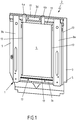
- Figure 1 shows in a plan view from the side of the frame-shaped metal support structure 1 a plan view of a support structure according to the invention, altogether denoted by 2.
- This support structure comprises the frame-shaped metal support structure 1 which is composed of four metal slats or metal profiles 3a, 3b, 3c, 3d as a substantially rectangular frame by welding the individual metal slats or metal profiles 3a to 3d together.
- the metal slats or metal profiles 3a to 3d span the frame-shaped metal support structure 1 and form a free space between each other on the inner frame side.
- Two sleeves 4a, 4b are welded to the - according to the illustration in Figure 1 - upper metal profile 3d, which serve as attachment of headrests or of a headrest support structure.
- the position of the support structure 2 shown in Figure 1 also corresponds to the later mounting position thereof in a motor vehicle inasmuch as the side comprising the sleeves 4a, 4b is associated with the upper region of a seat back and the frame-shaped metal support structure 1 faces the front side of a motor vehicle.
- a plane nonwoven fiber fleece formed component 5 is applied by material bonded engagement to respectively one outer side or outer surface of each of the metal slats or metal profiles 3a to 3d in a way to span the metal support structure 1, in particular connected to the respective outer side or outer surface of the metal slats or metal profiles 3a to 3d or applied thereto.
- the individual outer sides or outer surfaces of the metal slats or metal profiles 3a to 3d lie in one plane.
- This connection by material bonded engagement 6 between the frame-shaped metal support structure 1 and the at least one nonwoven fiber fleece formed component 5 is formed as an adhesive layer 6a which consists of a cross-linked polyurethane hot melt adhesive, thus forming a cross-linked polyurethane hot melt adhesive layer 6b.
- This at least one nonwoven fiber fleece formed component 5 is a thermoplastically bound, plane nonwoven fiber fleece formed component thermally compression-molded by a thermal molding process.
- This nonwoven fiber fleece formed component 5 was thermally compression-molded from a nonwoven glass fiber fleece composed of structure-forming glass fibers and having a specific weight of 350 g/m 2 to 500 g/m 2 and charged with a polyurethane amount of 350 g/m 2 to 500 g/m 2 as a binding agent.
- This nonwoven fiber fleece formed component 5 may have a rigidity of 6 N/mm to 8 N/mm expressed as a thickness-related elastic modulus.
- the nonwoven fiber fleece formed component may also be a plane nonwoven fiber fleece formed component 5 thermally compression-molded from a nonwoven fiber fleece composed of a mixture of structure-forming glass fibers and thermally deformable, matrix-forming polypropylene fibers (PP) as a binding agent and having a specific weight of 900 g/m 2 to 1200 g/m 2 , which may also have a rigidity of 6 N/mm to 8 N/mm expressed as a thickness-related elastic modulus.
- PP matrix-forming polypropylene fibers
- the at least one, thermoplastically bound, plane nonwoven fiber fleece formed component 5 already forms a plane nonwoven fiber fleece support structure 7 in its thermally compression-molded structure.
- the support structure 2 of a seat back of a vehicle seat or of a back seat of a motor vehicle then comprises the frame-shaped metal support structure 1 and the plane nonwoven fiber fleece support structure 7, wherein the frame-shaped metal support structure 1 is at least substantially composed of metal slats or metal profiles 3a to 3d, and thereon, on one side of the frame-shaped metal support structure 1, a thermoplastically bound, plane nonwoven fiber fleece formed component 5 is disposed, spanning the metal support structure 1 on this side, which is composed of structure-forming fibers, in particular glass fibers, and a matrix-forming binding agent, in particular polyurethane (PU) or thermoplastically deformable fibers, preferably polypropylene fibers, and forms the plane nonwoven fiber fleece support structure 7.
- PU polyurethane
- thermoplastically deformable fibers preferably polypropylene fibers
- the plane nonwoven fiber fleece support structure is, however, formed by a reinforced nonwoven fiber fleece support structure 7 forming a sandwich structure, which in addition to the at least one nonwoven fiber fleece formed component 5 comprises a honeycombed paper structure 8 and a second plane nonwoven fiber fleece formed component 9.
- the honeycombed paper structure 8 has a specific paper weight of 140 g/m 2 to 160 g/m 2 and a cell width of the honeycombs of between 6 mm and 8 mm.
- the at least one, plane nonwoven fiber fleece formed component 5 is connected by material bonded engagement on a first outer side 10 of the honeycombed paper structure 8 by its lower side 11 to the honeycombed paper structure 8.
- connection by material bonded engagement is established by means of a polyolefin film 12 which has a specific weight of 60 g/m 2 to 100 g/m 2 and which is laid and thermoplastically deformed between the first outer side 10 of the honeycombed paper structure 8 and the lower side 11 of the at least one plane nonwoven fiber fleece formed component 5 to be connected to the honeycombed paper structure 8 by material bonded engagement.
- the honeycombed paper structure 8 is, according to the exemplary embodiment, also connected by material bonded engagement to the second nonwoven fiber fleece formed component 9 on the opposite side by means of another polyolefin film 13.
- the thermoplastically bound, second plane nonwoven fiber fleece formed component 9 is fixed on a second outer side 14 of the honeycombed paper structure 8 opposite the first outer side 10 of the honeycombed paper structure 8.
- the polyolefin film 13 chosen for forming the connection by material bonded engagement also has a specific weight of 60 g/m 2 to 100 g/m 2 and is, in turn laid between the second outer side 14 of the honeycombed paper structure 8 and a lower side 15 of the second plane nonwoven fiber fleece formed component 9 to be connected by material bonded engagement to the honeycombed paper structure 8, and is thermoplastically deformed, thereby forming the connection by material bonded engagement.
- the second plane nonwoven fiber fleece formed component 9 is also made by means of a thermal molding process of a nonwoven glass fiber fleece composed of structure-forming glass fibers and having a specific weight of 350 g/m 2 to 500 g/m 2 and charged with a polyurethane amount of 350 g/m 2 to 500 g/m 2 as a binding agent or of a nonwoven fiber fleece composed of a mixture of structure-forming glass fibers and thermally deformable, matrix-forming polypropylene fibers (PP) as a binding agent and having a specific weight of 900 g/m 2 to 1200 g/m 2 .
- PP matrix-forming polypropylene fibers
- the nonwoven fiber fleece formed component 9 made of the glass fibers and polyurethane (PU) as a binding agent by thermal compression molding may have a rigidity of 6 N/mm to 8 N/mm expressed as a thickness-related elastic modulus.
- the nonwoven fiber fleece thermally compression-molded from the mixture of polypropylene fibers (PP) and glass fibers may have a rigidity of 6 N/mm to 8 N/mm expressed as a thickness-related elastic modulus.
- PP polypropylene fibers
- the sandwich construction 18 formed by the first and second nonwoven fiber fleece formed components 6, 9 and the honeycombed paper structure 8 has a rigidity of 6 N/mm to 8 N/mm expressed as a thickness-related elastic modulus.
- Both the nonwoven fiber fleece support structure made of a single nonwoven fiber fleece formed component 5 and the plane nonwoven fiber fleece support structure 7 configured in a sandwiched way according to the embodiment respectively have a thickness D of 5 mm to 10 mm, in particular 6 mm to 9 mm.
- the thickness of the nonwoven fiber fleece support structure 7 is measured in its final form, from the upper side of the nonwoven fiber fleece formed component 5 to be connected to the metal support structure 1 to the opposite outer side formed by an outer side of the second nonwoven fiber fleece formed component 9. If the nonwoven fiber fleece support structure 7 only comprises the at least one nonwoven fiber fleece formed component 5, this thickness D is measured between the two opposite outer sides of the nonwoven fiber fleece formed component 5.
- Any decoration or carpet pile layers 16, applied to the nonwoven fiber fleece formed component 5 or the second nonwoven fiber fleece formed component 9, as suggested in dots in Figure 2 are to be disregarded when determining the thickness.
- the respective nonwoven fiber fleece formed component 5, 9 may, in addition to the glass fiber layer provided with polyurethane or in addition to the layer constituted as a mixture of glass fibers and polypropylene fibers, may be provided with a pinned layer of a polyethylene terephthalate (PET) / polypropylene (PP) fiber mixture having a specific weight of 150 g/m 2 to 250 g/m 2 , preferably 180 g/m 2 to 220 g/m 2 .
- PET polyethylene terephthalate
- PP polypropylene
- the entirety of laid nonwoven glass fiber fleece with added polyurethane binding agent and pinned layer or the entirety of nonwoven glass fiber fleece with blended polypropylene fibers and pinned layer is thermally compression-molded to a or the nonwoven fiber fleece formed component(s) 5, 9.
- the surface of the at least one and/or of the second nonwoven fiber fleece formed component 5, 9 respectively opposed to the pinned layer is connected to the honeycombed paper structure 8 by material bonded engagement.
- the support structure 2 consisting of the frame-shaped metal structure 1 and the nonwoven fiber fleece support structure 7 has rigidity values of the frame-shaped metal structure 1 and nonwoven fiber fleece support structure 7 matched with each other in such a way, as well as such a strength value of the polyurethane hot melt adhesive bond 6, 6a, 6b connecting the frame-shaped metal support structure 1 and the nonwoven fiber fleece support structure 7 by material bonded engagement that the support structure 2 provided in such a way, installed in a seat back of a vehicle seat or a rear seat of a motor vehicle, resists the crash test loads of the motor vehicle occurring upon application of the DIN ISO standard 27955:2012.
- the metal profiles 3a to 3d are profiled sheets comprising ridges 17 projecting laterally from their base.
- the outer sides of the ridges 17 are respectively on one level and therefore form a plane of a common outer side or outer surface onto which then the at least one nonwoven fiber fleece 5 of the plane nonwoven fiber fleece support structure 7 is adhered.
- the frame-shaped metal support structure 1 and the nonwoven fiber fleece support structure 7 are first separately manufactured in separate manufacturing steps and are then joined together in another manufacturing step to form the support structure 2 according to the invention.
- the frame-shaped metal support structure 1 is manufactured by welding together the metal slats or metal profiles 3a to 3d.
- the nonwoven fiber fleece support structure 7 is produced by carding, cross-lapping and pinning of a respectively desired or necessary fiber amount and mixture into a fiber glass nonwoven fiber fleece or nonwoven fiber fleece, where appropriate by admixing adhesive, and subsequent thermal compression-molding of the nonwoven glass fiber fleece or nonwoven fiber fleece to a nonwoven fiber fleece formed component 5, if this nonwoven fiber fleece formed component 5 already forms the nonwoven fiber fleece support structure 7.
- the nonwoven fiber fleece support structure 7 is made of a sandwiched structure with the sandwich construction 18, the nonwoven fiber fleeces manufactured as described are respectively laid onto respectively one side of a honeycombed paper structure 8, by interpositioning a polyolefin film 12, 13, and are then thermally compression-molded to form the nonwoven fiber fleece support structure 7 in a thermal compression-molding process.
- the frame-shaped metal support structure 1 is placed and the surface sides of the ridges 17 to be glued together with the nonwoven fiber fleece support structure 7 are provided with a polyurethane hot melt adhesive, and then, in a pressing process, the nonwoven fiber fleece support structure 7 comprising the at least one nonwoven fiber fleece formed component 5 and formed thereby or the nonwoven fiber fleece support structure 7 comprising the other, second nonwoven fiber fleece formed component 9 as well as the honeycombed paper structure 8 is laid onto the ridges 17 provided with adhesive and is, by application of pressure and temperature for cross-linking the polyurethane adhesive 6b, pressed together, thereby forming a connection 6 by material bonded engagement.
- the at least one thermoplastically bound, plane nonwoven fiber fleece formed component 5 is configured in a way to have a rigidity of 6 N/mm to 8 N/mm expressed as a thickness-related surface elastic modulus when forming the nonwoven fiber fleece support structure 7.
- a rigidity of 6 N/mm to 8 N/mm expressed as a thickness-related surface elastic modulus when forming the nonwoven fiber fleece support structure 7.
- at least the nonwoven fiber fleece support structure 7 constructed in a sandwich-like way (sandwich construction 18) altogether has the rigidity of 6 N/mm to 8 N/mm expressed as a thickness-related elastic modulus.
Landscapes
- Engineering & Computer Science (AREA)
- Mechanical Engineering (AREA)
- Textile Engineering (AREA)
- Aviation & Aerospace Engineering (AREA)
- Transportation (AREA)
- Laminated Bodies (AREA)
Description
- The invention is directed to a support structure for a seat back of a vehicle seat or of a back seat of a motor vehicle, comprising a frame-shaped metal support structure and a plane nonwoven fiber fleece structure, wherein the frame-shaped metal support structure is composed at least substantially of metal slats or metal profiles and comprises at least one thermoplastically bound, plane, nonwoven fiber fleece formed component disposed on one side of the frame-shaped metal support structure and spanning the metal support structure on this side, which is composed of structure-forming fibers, in particular glass fibers, and a matrix-forming binding agent, in particular polyurethane (PU), or thermoplastically deformable fibers, preferably polypropylene fibers, and forms the plane nonwoven fiber fleece support structure or is part of the plane nonwoven fiber fleece support structure.
- Similarly, the invention is directed to a method of manufacturing a support structure for a seat back of a vehicle seat or of a back seat of a motor vehicle, comprising a frame-shaped metal support structure and a plane nonwoven fiber fleece support structure, wherein the frame-shaped metal support structure is composed at least substantially of metal slats or metal profiles and comprises at least one thermoplastically bound, plane nonwoven fiber fleece formed component disposed on one side of the frame-shaped metal support structure and spanning the metal support structure on this side, which is composed of structure-forming fibers, in particular glass fibers, and a matrix-forming binding agent, in particular polyurethane (PU), or thermoplastically deformable fibers, preferably polypropylene fibers, and forms the plane nonwoven fiber fleece support structure or is part of the plane nonwoven fiber fleece support structure.
- The substantial element imparting the necessary stability to the seat back of a vehicle seat of a motor vehicle forms the support structure thereof. In particular in seat backs of a vehicle seat positioned at the rear of a vehicle, especially in the second or in the last seat row of a motor vehicle or a back seat, this support structure in practice frequently consists of a metal structure made of various metal slats or metal profiles in a rectangular or frame shape and having a metal sheet connecting the metal slats or metal profiles and frequently formed between these. This metal sheet is surfaced with a nonwoven fiber fleece or a carpet pile toward the vehicle rear where the loading area or the trunk are typically located. This frame structure needs to have such a rigidity and strength that the seat back of a vehicle seat provided with a support structure of this type fulfils the requirements and the test procedure according to the DIN ISO standard 27955:2012 in a vehicle crash test.
- Given that this metal support structure is composed of metal, in particular steel elements, i.e. steel slats or steel profiles and at least one steel sheet, the support structure has a relatively high weight. In addition, the production of a support structure of this type is associated with a relatively high manufacturing effort, given that first the frame-shaped steel structure needs to be welded, a sheet needs to be molded and punched, and then the sheet needs to be welded onto the steel structure, before then either a plane carpet part supplied with adhesive is adhered to the entire surface of the sheet or a carpet element is formed and is connected to the sheet by an adhesive strip or by means of clipping.
- Therefore, alternative support structures have become known as well, which have been developed in the light of reducing the weight of the entire component, i.e. the support structure, and which may be manufactured easily.
- In this respect, a support structure of a seat back of a vehicle is known from
DE 10 2016 217 952 A1 , which is composed of a frame-shaped metal structure and a synthetic material structure arranged in the area surrounded by the frame-shaped metal structure, wherein the synthetic material support structure with its substantially spider web and honeycombed synthetic material body is formed and disposed in the frame inner region spanned by the metal frame, and support structure elements of the metal construction are extrusion-coated with synthetic material portions of the synthetic material support structure. In this support structure, the synthetic material construction and the synthetic material support structure, respectively, is manufactured as a single-piece injection-molded component which is made of a thermoplastic material which is in particular fiber-reinforced. Advantageously, the necessary rigidity and strength of the support structure are substantially achieved by the specific rigidity of the synthetic material structure in this embodiment. However, it is a drawback of this support structure that a relatively massive synthetic material formed component has to be manufactured and connected to the metal support structure which also still has a relatively high weight - also as compared to a sheet which has typically been used before. Given that this synthetic material construction is, in addition, to be configured in a reticular and honeycombed way, a quite complicated and complex injection mold is required in this case. - In another development according to the disclosure of
DE 10 2010 005 456 A1 , the fabrication of so-called organic sheets or hybrid yarn fabrics or hybrid fiber woven fabrics has been proposed, as well as their arrangement in sandwich components as surface layers on a honeycomb core formed by a plurality of paper ridges. A support structure of this type, no longer comprising a metal support structure, may, however, fulfil the rigidity and strength requirements to be fulfilled in crash tests only if it is configured to be very thick or if it is manufactured using particularly expensive and high-strength reinforcement and binding fibers. For reasons of cost, the search for a solution which provides a support structure having a reduced weight as compared to a pure metal or steel support structure but nevertheless being able to be produced within acceptable cost limits is still going on. - An automotive component formed by a honeycombed core layer of paper or cardboard having cover layers of a thermoplastic fiber material disposed on both sides thereof is, in addition, known from
AT 519010 B1 - In addition, a composite component also consisting of a paper honeycomb or flexible polyurethane foam core layer and glass fiber layers applied to both sides thereof, into which a metal wire reinforcing element formed in a profiled way is embedded, is known from
DE 10 2007 007 554 A1 . This composite component is intended to be used in particular as a sliding headliner, rear shelf or load surface. -
WO 2017/194687 A1 andDE 10 2009 059975 A1 disclose other examples of support structures from the prior art. - The object underlying the invention is to create a solution which provides a support structure of a seat back of a vehicle seat of a motor vehicle characterized by a favorable weight and a manufacturing effort favorable in respect of the materials to be used and their processing effort, which has a sufficient crash test strength and crash test rigidity.
- In a support structure of the initially mentioned type, this problem is, according to the invention, solved by the at least one thermoplastically bound, plane nonwoven fiber fleece formed component being a thermally compression-molded plane nonwoven fiber fleece formed component which forms the nonwoven fiber fleece support structure or a part of the nonwoven fiber fleece support structure and being joined by material bonded engagement, in particular glued together with, to respectively one outer side or outer surface of each of the metal slats or metal profiles which span the frame-shaped metal support structure, in a way spanning the metal support structure, wherein the nonwoven fiber fleece formed component and/or the nonwoven fiber fleece support structure comprising the nonwoven fiber fleece formed component have/has a rigidity of 6 N/mm to 8 N/mm, expressed as a thickness-related elastic modulus.
- Similarly, in a method according to the initially specified type, the aforementioned problem is solved by the frame-shaped metal support structure being provided and placed, and by a nonwoven fiber fleece, in particular a nonwoven glass fiber fleece, being provided and thermally compression-molded to the at least one, plane nonwoven fiber fleece formed component, wherein the nonwoven fiber fleece is compression-molded to the nonwoven fiber fleece formed component forming the plane nonwoven fiber fleece support structure or to a nonwoven fiber fleece formed component forming a part of the plane nonwoven fiber fleece support structure in such a way that the respective plane nonwoven fiber fleece support structure has a rigidity of 6 N/mm to 8 N/mm expressed as a thickness-related elastic modulus, and that the respective at least one plane nonwoven fiber fleece formed component obtained in such a way and forming the nonwoven fiber fleece support structure or forming a part of the nonwoven fiber fleece support structure is joined by material bonded engagement, in particular glued together with, to respectively one outer side or outer surface of each of the metal slats or metal profiles which span the provided fame-shaped metal support structure, in a way spanning the placed metal support structure.
- Accordingly, the support structure according to the invention stands out by its configuration as a hybrid support structure which, on the one hand, comprises a frame-shaped metal support structure which is substantially formed as a frame formed by metal slats or metal profiles, and in which on one side of the frame a nonwoven fiber fleece support structure formed by a nonwoven fiber fleece formed component or comprising a nonwoven fiber fleece formed component is adhered by material bonded engagement and in a way spanning the metal structure to an outer side or outer surface of the metal support structure formed by the metal slats or metal profiles, and thus to the frame. In this respect, the plane nonwoven fiber fleece formed component forming at least a part of the nonwoven fiber fleece support structure in particular has a rigidity of 6 N/m to 8 N/mm expressed as a thickness-related elastic modulus when forming the nonwoven fiber fleece support structure. In a sandwich structure only comprising the at least one nonwoven fiber fleece formed component, the nonwoven fiber fleece support structure has - just like in the case in which it is already formed by the nonwoven fiber fleece formed component - altogether a rigidity of 6 N/mm to 8 N/mm expressed as a thickness-related elastic modulus. A nonwoven fiber fleece support structure of this type has, together with the frame-shaped metal support structure to which it is joined by material bonded engagement, the necessary crash test strength and crash test rigidity that a support structure of a seat back of a motor vehicle seat or a rear seat of a motor vehicle should have.
- A support structure according to the invention of this type is, on the one hand, characterized by a relatively low weight, given that the metal support structure needs to be formed only by a frame composed of metal slats or metal profiles and in that, instead of a metal sheet stabilizing this frame, now a plane nonwoven fiber fleece formed component or a plane nonwoven fiber fleece support structure is fixed, in particular adhered, in a way spanning the spanned frame surface, to the frame or to a plane-spanning common surface side of the metal slats or metal profiles forming and spanning this frame. In addition, the manufacturing effort for manufacturing a support structure of this type is reduced as well, given that only the metal slats or metal profiles have to be welded to the metal frame, i.e. to the frame-shaped metal support structure, and a nonwoven fiber fleece formed component or the nonwoven fiber fleece support structure has to be manufactured in the context of a typical thermal molding process from a nonwoven fiber fleece or a nonwoven glass fiber fleece - as the case may be in combination with a honeycombed paper structure. Another manufacturing step then consists of joining together the metal support structure and the nonwoven fiber fleece support structure by material bonded engagement. The processing effort and the materials to be used require a favorable production effort comprising only a few production steps or are characterized by a favorable production effort only requiring a few production steps, wherein the obtained support structure nevertheless meets the necessary crash test conditions with respect to its necessary strength and rigidity. To put it simply, the invention provides a nonwoven fiber fleece support structure which replaces the metal sheet, in particular the steel sheet, hitherto common in practice in metal support structures, arranged within the frame-shaped metal support structure or spanning the same, and wherein the necessary crash test requirements are nevertheless fulfilled by the support structure.
- The nonwoven fiber fleece formed component and thus the nonwoven fiber fleece support structure is formed by means of a common compression molding process preferably as a plane nonwoven fiber fleece formed component thermally compression-molded from a nonwoven glass fiber fleece composed of structure-forming glass fibers and having a specific weight of 350 g/m2 to 500 g/m2 and charged with a polyurethane amount of 350 g/m2 to 500 g/m2 as a binding agent. Alternatively, the nonwoven fiber fleece formed component and thus the nonwoven fiber fleece support structure may in particular also be configured as a plane nonwoven fiber fleece formed component thermally compression-molded from a nonwoven fiber fleece composed of a mixture of structure-forming glass fibers and thermally deformable, matrix-forming polypropylene fibers as a binding agent and having a specific weight of 900 g/m2 to 1200 g/m2. Therefore, according to an embodiment of the invention, the at least one thermoplastically bound, plane nonwoven fiber fleece formed component either is a plane nonwoven fiber fleece formed component thermally compression-molded from a nonwoven glass fiber fleece composed of structure-forming glass fibers and having a specific weight of 350 g/m2 to 500 g/m2 and charged with a polyurethane amount of 350 g/m2 to 500 g/m2 as a binding agent, or a plane nonwoven fiber fleece formed component thermally compression-molded from a nonwoven fiber fleece composed of a mixture of structure-forming glass fibers and thermally deformable, matrix-forming polypropylene fibers (PP) as a binding agent and having a specific weight of 900 g/m2 to 1200 g/m2.
- According to an advantageous embodiment of the invention, a reinforced nonwoven fiber fleece support structure may be configured by the at least one plane nonwoven fiber fleece formed component being fixed by material bonded engagement to a first outer side of a honeycombed paper structure for forming a reinforced nonwoven fiber fleece support structure, wherein the honeycombed paper structure has a specific paper weight of 140 g/m2 to 160 g/m2 and the honeycombs of which have a cell width of between 6 mm and 8 mm.
- In order to be able to join a plane nonwoven fiber fleece formed component to the honeycombed paper structure, a connection by means of a polyolefin film is advantageous. The invention is therefore further characterized in that the at least one plane nonwoven fiber fleece formed component is joined by material bonded engagement to the honeycombed paper structure by means of a polyolefin film having a specific weight of 60 g/m2 to 100 g/m2 and laid and thermoplastically deformed between the first outer side of the honeycombed paper structure and a lower side of the at least one plane nonwoven fiber fleece formed component to be joined by material bonded engagement to the honeycombed paper structure.
- The nonwoven fiber fleece support structure may also comprise another, second plane nonwoven fiber fleece formed component which is also attached to the honeycombed paper structure by material bonded engagement. According to another embodiment, the invention is therefore characterized in that, for forming a further reinforced nonwoven fiber fleece support structure, a thermoplastically bound, second plane nonwoven fiber fleece formed component is fixed by material bonded engagement to a second outer side of the honeycombed paper structure opposed to the first outer side of the honeycombed paper structure, in particular connected to the honeycombed paper structure by material bonded engagement by means of another polyolefin film which has a specific weight of 60 g/m2 to 100 g/m2 and which is laid and thermoplastically deformed between the second outer side of the honeycombed paper structure and a lower side of the second plane nonwoven fiber fleece formed component to be connected to the honeycombed paper structure by material bonded engagement.
- The second plane nonwoven fiber fleece formed component may be configured like the at least one, first plane nonwoven fiber fleece formed component, so that according to an embodiment of the invention, the second plane nonwoven fiber fleece formed component is either a plane nonwoven fiber fleece formed component thermally compression-molded from a nonwoven glass fiber fleece composed of structure-forming glass fibers and having a specific weight of 350 g/m2 to 500 g/m2 and being charged with a polyurethane amount of 350 g/m2 to 500 g/m2 as a binding agent, or is a plane nonwoven fiber fleece formed component thermally compression-molded from a nonwoven fiber fleece composed of a mixture of structure-forming glass fibers and thermally deformable, matrix-forming polypropylene fibers (PP) as a binding agent and having a specific weight of 900 g/m2 to 1200 g/m2.
- The rigidity of the support structure is also substantially determined and influenced by the rigidity of the nonwoven fiber fleece formed component and the rigidity of the respective nonwoven fiber fleece support structure, respectively. According to an embodiment, the invention is therefore characterized in that the nonwoven fiber fleece formed component has a rigidity of 6 N/mm to 8 N/mm expressed as a thickness-related elastic modulus when forming the plane nonwoven fiber fleece support structure, or in that the at least one nonwoven fiber fleece formed component and/or the second nonwoven fiber fleece formed component have/has a rigidity of 6 N/mm to 8 N/mm expressed as a thickness-related elastic modulus when they are part of the plane nonwoven fiber fleece support structure, or that a sandwich construction comprising the at least one nonwoven fiber fleece formed component and the second nonwoven fiber fleece formed component and the honeycombed paper structure has a rigidity of 6 N/mm to 8 N/mm expressed as a thickness-related elastic modulus when being part of the nonwoven fiber fleece support structure or forming the same.
- An appropriate fiber mixture for producing the at least one or second nonwoven fiber fleece formed component may also comprise polyethylene terephthalate fibers and polypropylene fibers. It is therefore, in addition, advantageous if the at least one and/or the second nonwoven fiber fleece formed component is a nonwoven fiber fleece formed component thermally compression-molded from the, in particular laid, nonwoven glass fiber fleece with an additionally pinned layer of a polyethylene terephthalate (PET) / polypropylene (PP) fiber mixture having a specific weight of 150 g/m2 to 250 g/m2, preferably 180 g/m2 to 220 g/m2, or a nonwoven fiber fleece formed component thermally compression-molded from the fiber mixture comprising in particular laid glass fibers and polypropylene fibers with an additionally pinned layer of a polyethylene terephthalate (PET) / polypropylene (PP) fiber mixture having a specific weight of 150 g/m2 to 250 g/m2, preferably 180 g/m2 to 220 g/m2, which is also provided for by the invention. Here, it then is in particular advantageous if the surface of the at least one and/or the second nonwoven fiber fleece formed component opposed to the pinned layer is respectively connected to the honeycombed paper structure by material bonded engagement.
- It has further turned out that it is sufficient for obtaining the necessary rigidity of the support structure according to the invention that the at least one plane nonwoven fiber fleece formed component should form a nonwoven fiber fleece support structure compression-molded to a thickness of 5 mm to 10 mm, in particular 6 mm to 9 mm or that the sandwich construction formed by the honeycombed paper structure and the at least one plane nonwoven fiber fleece formed component and/or the second plane nonwoven fiber fleece formed component should form a nonwoven fiber fleece support structure compression-molded to a thickness of 5 mm to 10 mm, in particular 6 mm to 9 mm, by which the invention is characterized as well.
- In the usual manner, one side of the nonwoven fiber fleece support structure, typically the surface of the plane nonwoven fiber fleece support structure oriented toward the rear side of the motor vehicle, may be provided with a decoration or a carpet pile, which in particular results in another improvement extending beyond the acoustic behavior of the vehicle trunk with respect to the vehicle interior, already improved by the nonwoven fiber fleece support structure configured according to the invention. Therefore, according to the invention, the at least one or the second nonwoven fiber fleece formed component is laminated with a decoration or a carpet pile on its side facing away from the metal support structure.
- In order to achieve in particular the required crash test strength and crash test rigidity, the configuration of the connection by material bonded engagement between the metal support structure and the nonwoven fiber fleece support structure is configured in a particularly advantageous manner if the connection by material bonded engagement between the metal support structure and the at least one nonwoven fiber fleece formed component is configured as a polyurethane hot melt adhesive layer cross-linked between the metal support structure and the nonwoven fiber fleece support structure, which is also further provided by the invention.
- According to another embodiment of the invention, it is in particular appropriate and advantageous that the support structure consisting of the frame-shaped metal support structure and the nonwoven fiber fleece support structure has rigidity values of the frame-shaped metal support structure and the plane nonwoven fiber fleece support structure matched with each other in such a way, as well as such a strength value of the polyurethane hot melt adhesive bond connecting the frame-shaped metal support structure and the at least one nonwoven fiber fleece formed component of the nonwoven fiber fleece support structure by material bonded engagement, that the support structure provided in such a way, installed in a seat back of a vehicle seat or a back seat of a motor vehicle, resists the crash test loads of the motor vehicle occurring upon application of the DIN ISO standard 27955:2012.
- In a particularly advantageous way, the support structure according to the invention may be manufactured by using a method according to any one or more of
claims 15 to 31. This method is characterized by only a small number of manufacturing steps, so that manufacturing the support structure requires only a slight, favorable manufacturing effort. - In particular, the nonwoven fiber fleece formed component is made from a nonwoven glass fiber fleece or a nonwoven fiber fleece containing glass fibers, which is why, according to an embodiment of the invention, either a nonwoven glass fiber fleece composed of structure-forming glass fibers having a specific weight of 350 g/m2 to 500 g/m2 is provided as a nonwoven fiber fleece and charged with a polyurethane amount of 350 g/m2 to 500 g/m2 as a binding agent and is thermally compression-molded to the at least one plane nonwoven fiber fleece formed component (5) or a nonwoven fiber fleece composed of a mixture of structure-forming glass fibers and thermally deformable, matrix-forming polypropylene fibers (PP) as a binding agent having a specific weight of 900 g/m2 to 1200 g/m2 is provided as a nonwoven fiber fleece and thermally compression-molded to the at least one plane nonwoven fiber fleece formed component (5).
- Like the support structure according to the invention, the method according to the invention is in one embodiment also characterized in that the nonwoven glass fiber fleece or the nonwoven fiber fleece or the at least one plane nonwoven fiber fleece formed component is fixed by material bonded engagement to a first outer side of a honeycombed paper structure prior to the connection by material bonded engagement, in particular adhesion, of the at least one plane nonwoven fiber fleece formed component to the frame-shaped metal support structure for forming a reinforced nonwoven fiber fleece support structure, wherein the honeycombed paper structure has a specific paper weight of 140 g/m2 to 160 g/m2 and the honeycombs of which have a cell width of between 6 mm and 8 mm.
- Here, the nonwoven glass fiber fleece or the nonwoven fiber fleece or the at least one plane nonwoven fiber fleece formed component may be connected to the honeycombed paper structure by material bonded engagement, which is also provided for by the invention, by means of a polyolefin film which has a specific weight of 60 g/m2 to 100 g/m2 and which is laid and heated between the first outer side of the honeycombed paper structure and a lower side of the nonwoven glass fiber fleece or of the nonwoven fiber fleece or of the at least one plane nonwoven fiber fleece formed component to be connected to the honeycombed paper structure by material bonded engagement and which is then thermoplastically deformed by pressing together the honeycombed paper structure and the nonwoven glass fiber fleece or the nonwoven fiber fleece or the plane nonwoven fiber fleece formed component.
- Advantageously, for forming a further reinforced nonwoven fiber fleece support structure, another, second plane nonwoven fiber fleece formed component is connected to the honeycombed paper structure prior to the adhesion of the at least one plane nonwoven fiber fleece formed component. For this purpose, according to a further embodiment of the invention, a second nonwoven glass fiber fleece or a second nonwoven fiber fleece or a thermoplastically bound, second plane nonwoven fiber fleece formed component is fixed by material bonded engagement to a second outer side of the honeycombed paper structure opposed to the first outer side of the honeycombed paper structure prior to the connection by material bonded engagement, in particular adhesion of the at least one plane nonwoven fiber fleece formed component to the metal support structure for forming a further reinforced nonwoven fiber fleece support structure.
- The second plane nonwoven fiber fleece formed component may also be connected by material bonded engagement to the honeycombed paper structure by means of a polyolefin film, for which purpose, according to the invention, the second nonwoven glass fiber fleece or the second nonwoven fiber fleece or the second plane nonwoven fiber fleece formed component is connected by material bonded engagement to the honeycombed paper structure by means of another polyolefin film which has a specific weight of 60 g/m2 to 100 g/m2 and which is laid and heated between the second outer side of the honeycombed paper structure and a lower side of the second nonwoven glass fiber fleece or the second nonwoven fiber fleece or the second plane nonwoven fiber fleece formed component to be connected by material bonded engagement to the honeycombed paper structure, and which is then thermoplastically deformed by pressing together the honeycombed paper structure and the second plane nonwoven fiber fleece formed component.
- For manufacturing the nonwoven glass fiber fleece fiber fleece formed component or the sandwich construction, nonwoven glass fiber fleeces or nonwoven fiber fleeces may be used which are configured to be identical to those used in the manufacturing of the at least one, first nonwoven fiber fleece formed component. Therefore, according to a further embodiment of the invention, a nonwoven glass fiber fleece is provided for attachment to or connection to the honeycombed paper structure as a second nonwoven glass fiber fleece as well, which is also composed of structure-forming glass fibers and has a specific weight of 350 g/m2 to 500 g/m2 and is charged with a polyurethane amount of 350 g/m2 to 500 g/m2 as a binding agent, or a nonwoven fiber fleece is provided for attachment to or connection to the honeycombed paper structure as a second nonwoven fiber fleece, which is composed of a mixture of structure-forming glass fibers and thermally deformable, matrix-forming polypropylene (PP) fibers as a binding agent and has a specific weight of 900 g/m2 to 1200 g/m2.
- The second plane nonwoven fiber fleece formed component may be configured just like the at least one, first plane nonwoven fiber fleece formed component, so that the invention is, in addition, characterized in that either a nonwoven glass fiber fleece composed of structure-forming glass fibers and having a specific weight of 350 g/m2 to 500 g/m2 and being charged with a polyurethane amount of 350 g/m2 to 500 g/m2 as a binding agent is thermally compression-molded to the second plane nonwoven fiber fleece formed component, or a nonwoven fiber fleece composed of a mixture of structure-forming glass fibers and thermally deformable, matrix-forming polypropylene (PP) fibers as a binding agent and having a specific weight of 900 g/m2 to 1200 g/m2 is thermally compression-molded to the second plane nonwoven fiber fleece formed component, and that the respective second nonwoven fiber fleece formed component is provided for attachment or connection to the honeycombed paper structure.
- Advantageously, the second plane nonwoven fiber fleece formed component is compression-molded in a way to have a rigidity of 6 N/mm to 8 N/mm expressed as a thickness-related elastic modulus.
- Preferably, the connections by material bonded engagement of the nonwoven glass fiber fleece or the nonwoven fiber fleece or the at least one and the second plane nonwoven fiber fleece formed component to the honeycombed paper structure are carried out in a compression mold which is preferably heatable, preferably in one process step, which is also provided according to an embodiment of the invention.
- According to an embodiment of the invention, the nonwoven fiber fleece formed structure has a rigidity of 6 N/mm to 8 N/mm expressed as a thickness-related elastic modulus. Here, the nonwoven fiber fleece support structure may be configured and compression-molded in such a way that the at least one nonwoven fiber fleece formed component has a rigidity of 6 N/mm to 8 N/mm expressed as a thickness-related elastic modulus when forming the nonwoven fiber fleece support structure, or alternatively, the at least one nonwoven fiber fleece formed component and/or the second nonwoven fiber fleece formed component may have a rigidity of 6 N/mm to 8 N/mm expressed as a thickness-related elastic modulus when forming part of the plane nonwoven fiber fleece support structure, or, as an alternative, a sandwich construction comprising the at least one nonwoven fiber fleece formed component and the second nonwoven fiber fleece formed component and the honeycombed paper structure may have a rigidity of 6 N/mm to 8 N/mm expressed as a thickness-related elastic modulus when forming part of the nonwoven fiber fleece support structure or forming the same.
- The respective nonwoven glass fiber fleece or the respective nonwoven fiber fleece formed component may, in addition, also comprise other fiber components. In this respect, according to an embodiment of the invention, the at least one and/or the second nonwoven fiber fleece formed component may be thermally compression-molded from the, in particular laid, nonwoven glass fiber fleece with an additionally pinned layer of a polyethylene terephthalate (PET) / polypropylene (PP) fiber mixture having a specific weight of 150 g/m2 to 250 g/m2, preferably 180 g/m2 to 220 g/m2, or the, in particular laid, fiber mixture comprising glass fibers and polypropylene fibers with an additionally pinned layer of a polyethylene terephthalate (PET) / polypropylene (PP) fiber mixture having a specific weight of 150 g/m2 to 250 g/m2, preferably 180 g/m2 to 220 g/m2. Here, the respective nonwoven fiber fleece formed component or the respective nonwoven glass fiber fleece or the respective nonwoven fiber fleece is advantageously positioned in a way that the surface of the respective at least one and/or of the respective second nonwoven fiber fleece formed component or of the respective nonwoven glass fiber fleece or of the respective nonwoven fiber fleece opposed to the pinned layer is respectively connected to the honeycombed paper structure by material bonded engagement, which is also provided for by the invention.
- As already illustrated with respect to the support structure, the nonwoven fiber fleece support structure advantageously has a thickness of 5 to 10 mm, in particular 6 to 9 mm. According to a further embodiment of the invention, the at least one plane nonwoven fiber fleece formed component is compression-molded to a nonwoven fiber fleece support structure having a thickness of 5 mm to 10 mm, in particular 6 mm to 9 mm, or the sandwich construction formed by the honeycombed paper structure and the at least one plane nonwoven fiber fleece formed component and/or the second plane nonwoven fiber fleece formed component is compression-molded to a nonwoven fiber fleece support structure having a thickness of 5 mm to 10 mm, in particular 6 mm to 9 mm. The nonwoven fiber fleece support structure or the nonwoven fiber fleece formed component may also be provided with a decoration or carpet pile. Therefore, the compression-molded at least one nonwoven fiber fleece formed component or the compression-molded second nonwoven fiber fleece formed component may, also according to the invention, be laminated with a decoration or carpet pile on its side facing away from the metal support structure.
- Given that the connection by material bonded engagement between the metal support structure and the nonwoven fiber fleece support structure has a particularly good strength and thereby causes a particularly good rigidity of the support structure if a polyurethane hot melt adhesive is used, the invention is, in addition, characterized in that the connection by material bonded engagement between the metal support structure and the at least one nonwoven fiber fleece formed component or the nonwoven fiber fleece support structure is established by means of an adhesive bond by application of a polyurethane hot melt adhesive onto the metal support structure and/or the nonwoven fiber fleece support structure, and the cross-linkage thereof.
- Eventually, according to an embodiment of the method according to the invention, the support structure consisting of the frame-shaped metal support structure and the nonwoven fiber fleece support structure is produced with rigidity values of the frame-shaped metal support structure and of the nonwoven fiber fleece support structure matched with each other in such a way, and with such a strength value of the polyurethane hot melt adhesive bond connecting by material bonded engagement the frame-shaped metal support structure and the at least one nonwoven fiber fleece formed component of the nonwoven fiber fleece support structure that the support structure provided in such a way and installed in a seat back of a vehicle seat or a rear seat of a motor vehicle resists the crash test loads occurring upon application of the DIN ISO standard 27955:2012.
- The preceding paragraphs and the claims illustrate that the at least one plane nonwoven fiber fleece formed component forming the plane nonwoven fiber fleece support structure or forming a part of the plane nonwoven fiber fleece support structure and/or the second nonwoven fiber fleece formed component forming a part of the plane nonwoven fiber fleece support structure and/or the nonwoven fiber fleece support structure is characterized by a rigidity of 6 N/mm to 8 N/mm expressed by a thickness-related elastic modulus. This kind of rigidity results from the fact that calculations in plane components are made using flows instead of stresses. In this respect, a thickness-related elastic modulus is applied, which corresponds to a rigidity and has the unit "N/mm".
- Hereinafter, the invention is illustrated in more detail by means of a drawing, in which:
- Figure 1
- shows a schematic perspective illustration of a plan view of a support structure according to the invention,
- Figure 2
- shows a schematic view of a section through the support structure according to
Figure 1 , and - Figure 3
- shows an enlarged section of
Figure 2 . -
Figure 1 shows in a plan view from the side of the frame-shaped metal support structure 1 a plan view of a support structure according to the invention, altogether denoted by 2. This support structure comprises the frame-shapedmetal support structure 1 which is composed of four metal slats ormetal profiles metal support structure 1 and form a free space between each other on the inner frame side. Other than in the exemplary embodiment shown herein, it is, however, also possible to arrange metal elements on the inner frame side in this free space, for example for fixing belt elements. Twosleeves Figure 1 -upper metal profile 3d, which serve as attachment of headrests or of a headrest support structure. The position of thesupport structure 2 shown inFigure 1 also corresponds to the later mounting position thereof in a motor vehicle inasmuch as the side comprising thesleeves metal support structure 1 faces the front side of a motor vehicle. On the rear side of the frame-shapedmetal structure 1 inFigure 1 and therefore in the position of use of thesupport structure 2 on the side of thesupport structure 2 facing the rear side of a motor vehicle, a plane nonwoven fiber fleece formedcomponent 5 is applied by material bonded engagement to respectively one outer side or outer surface of each of the metal slats or metal profiles 3a to 3d in a way to span themetal support structure 1, in particular connected to the respective outer side or outer surface of the metal slats or metal profiles 3a to 3d or applied thereto. The individual outer sides or outer surfaces of the metal slats or metal profiles 3a to 3d lie in one plane. This connection by material bonded engagement 6 between the frame-shapedmetal support structure 1 and the at least one nonwoven fiber fleece formedcomponent 5 is formed as anadhesive layer 6a which consists of a cross-linked polyurethane hot melt adhesive, thus forming a cross-linked polyurethane hot meltadhesive layer 6b. - This at least one nonwoven fiber fleece formed
component 5 is a thermoplastically bound, plane nonwoven fiber fleece formed component thermally compression-molded by a thermal molding process. This nonwoven fiber fleece formedcomponent 5 was thermally compression-molded from a nonwoven glass fiber fleece composed of structure-forming glass fibers and having a specific weight of 350 g/m2 to 500 g/m2 and charged with a polyurethane amount of 350 g/m2 to 500 g/m2 as a binding agent. This nonwoven fiber fleece formedcomponent 5 may have a rigidity of 6 N/mm to 8 N/mm expressed as a thickness-related elastic modulus. Alternatively, the nonwoven fiber fleece formed component may also be a plane nonwoven fiber fleece formedcomponent 5 thermally compression-molded from a nonwoven fiber fleece composed of a mixture of structure-forming glass fibers and thermally deformable, matrix-forming polypropylene fibers (PP) as a binding agent and having a specific weight of 900 g/m2 to 1200 g/m2, which may also have a rigidity of 6 N/mm to 8 N/mm expressed as a thickness-related elastic modulus. - In a first simple embodiment of the invention, the at least one, thermoplastically bound, plane nonwoven fiber fleece formed
component 5 already forms a plane nonwoven fiberfleece support structure 7 in its thermally compression-molded structure. In this constellation, thesupport structure 2 of a seat back of a vehicle seat or of a back seat of a motor vehicle then comprises the frame-shapedmetal support structure 1 and the plane nonwoven fiberfleece support structure 7, wherein the frame-shapedmetal support structure 1 is at least substantially composed of metal slats or metal profiles 3a to 3d, and thereon, on one side of the frame-shapedmetal support structure 1, a thermoplastically bound, plane nonwoven fiber fleece formedcomponent 5 is disposed, spanning themetal support structure 1 on this side, which is composed of structure-forming fibers, in particular glass fibers, and a matrix-forming binding agent, in particular polyurethane (PU) or thermoplastically deformable fibers, preferably polypropylene fibers, and forms the plane nonwoven fiberfleece support structure 7. - In the embodiment illustrated in
Figures 1 and2 , the plane nonwoven fiber fleece support structure is, however, formed by a reinforced nonwoven fiberfleece support structure 7 forming a sandwich structure, which in addition to the at least one nonwoven fiber fleece formedcomponent 5 comprises ahoneycombed paper structure 8 and a second plane nonwoven fiber fleece formedcomponent 9. - The
honeycombed paper structure 8 has a specific paper weight of 140 g/m2 to 160 g/m2 and a cell width of the honeycombs of between 6 mm and 8 mm. The at least one, plane nonwoven fiber fleece formedcomponent 5 is connected by material bonded engagement on a firstouter side 10 of thehoneycombed paper structure 8 by itslower side 11 to thehoneycombed paper structure 8. This connection by material bonded engagement is established by means of apolyolefin film 12 which has a specific weight of 60 g/m2 to 100 g/m2 and which is laid and thermoplastically deformed between the firstouter side 10 of thehoneycombed paper structure 8 and thelower side 11 of the at least one plane nonwoven fiber fleece formedcomponent 5 to be connected to thehoneycombed paper structure 8 by material bonded engagement. - For further reinforcement of the nonwoven fiber
fleece support structure 7, thehoneycombed paper structure 8 is, according to the exemplary embodiment, also connected by material bonded engagement to the second nonwoven fiber fleece formedcomponent 9 on the opposite side by means of anotherpolyolefin film 13. In this respect, the thermoplastically bound, second plane nonwoven fiber fleece formedcomponent 9 is fixed on a secondouter side 14 of thehoneycombed paper structure 8 opposite the firstouter side 10 of thehoneycombed paper structure 8. Thepolyolefin film 13 chosen for forming the connection by material bonded engagement also has a specific weight of 60 g/m2 to 100 g/m2 and is, in turn laid between the secondouter side 14 of thehoneycombed paper structure 8 and alower side 15 of the second plane nonwoven fiber fleece formedcomponent 9 to be connected by material bonded engagement to thehoneycombed paper structure 8, and is thermoplastically deformed, thereby forming the connection by material bonded engagement. - Analogously to the first plane nonwoven fiber fleece formed
component 5, the second plane nonwoven fiber fleece formedcomponent 9 is also made by means of a thermal molding process of a nonwoven glass fiber fleece composed of structure-forming glass fibers and having a specific weight of 350 g/m2 to 500 g/m2 and charged with a polyurethane amount of 350 g/m2 to 500 g/m2 as a binding agent or of a nonwoven fiber fleece composed of a mixture of structure-forming glass fibers and thermally deformable, matrix-forming polypropylene fibers (PP) as a binding agent and having a specific weight of 900 g/m2 to 1200 g/m2. The nonwoven fiber fleece formedcomponent 9 made of the glass fibers and polyurethane (PU) as a binding agent by thermal compression molding may have a rigidity of 6 N/mm to 8 N/mm expressed as a thickness-related elastic modulus. Similarly, the nonwoven fiber fleece thermally compression-molded from the mixture of polypropylene fibers (PP) and glass fibers may have a rigidity of 6 N/mm to 8 N/mm expressed as a thickness-related elastic modulus. Advantageously, only thesandwich construction 18 formed by the first and second nonwoven fiber fleece formedcomponents 6, 9 and thehoneycombed paper structure 8 has a rigidity of 6 N/mm to 8 N/mm expressed as a thickness-related elastic modulus. - Both the nonwoven fiber fleece support structure made of a single nonwoven fiber fleece formed
component 5 and the plane nonwoven fiberfleece support structure 7 configured in a sandwiched way according to the embodiment respectively have a thickness D of 5 mm to 10 mm, in particular 6 mm to 9 mm. In this respect, the thickness of the nonwoven fiberfleece support structure 7 is measured in its final form, from the upper side of the nonwoven fiber fleece formedcomponent 5 to be connected to themetal support structure 1 to the opposite outer side formed by an outer side of the second nonwoven fiber fleece formedcomponent 9. If the nonwoven fiberfleece support structure 7 only comprises the at least one nonwoven fiber fleece formedcomponent 5, this thickness D is measured between the two opposite outer sides of the nonwoven fiber fleece formedcomponent 5. Any decoration or carpet pile layers 16, applied to the nonwoven fiber fleece formedcomponent 5 or the second nonwoven fiber fleece formedcomponent 9, as suggested in dots inFigure 2 , are to be disregarded when determining the thickness. - According to another embodiment which is not shown, the respective nonwoven fiber fleece formed
component component honeycombed paper structure 8 by material bonded engagement. - Altogether, the
support structure 2 consisting of the frame-shapedmetal structure 1 and the nonwoven fiberfleece support structure 7 has rigidity values of the frame-shapedmetal structure 1 and nonwoven fiberfleece support structure 7 matched with each other in such a way, as well as such a strength value of the polyurethane hot meltadhesive bond metal support structure 1 and the nonwoven fiberfleece support structure 7 by material bonded engagement that thesupport structure 2 provided in such a way, installed in a seat back of a vehicle seat or a rear seat of a motor vehicle, resists the crash test loads of the motor vehicle occurring upon application of the DIN ISO standard 27955:2012. - As shown by
Figure 1 , the metal profiles 3a to 3d are profiledsheets comprising ridges 17 projecting laterally from their base. In the frame-shapedmetal support structure 1 fully welded together from the metal profiles 3a to 3d, the outer sides of theridges 17 are respectively on one level and therefore form a plane of a common outer side or outer surface onto which then the at least onenonwoven fiber fleece 5 of the plane nonwoven fiberfleece support structure 7 is adhered. - For manufacturing the
support structure 2 according to the invention, the frame-shapedmetal support structure 1 and the nonwoven fiberfleece support structure 7 are first separately manufactured in separate manufacturing steps and are then joined together in another manufacturing step to form thesupport structure 2 according to the invention. The frame-shapedmetal support structure 1 is manufactured by welding together the metal slats or metal profiles 3a to 3d. The nonwoven fiberfleece support structure 7 is produced by carding, cross-lapping and pinning of a respectively desired or necessary fiber amount and mixture into a fiber glass nonwoven fiber fleece or nonwoven fiber fleece, where appropriate by admixing adhesive, and subsequent thermal compression-molding of the nonwoven glass fiber fleece or nonwoven fiber fleece to a nonwoven fiber fleece formedcomponent 5, if this nonwoven fiber fleece formedcomponent 5 already forms the nonwoven fiberfleece support structure 7. In the event that the nonwoven fiberfleece support structure 7 is made of a sandwiched structure with thesandwich construction 18, the nonwoven fiber fleeces manufactured as described are respectively laid onto respectively one side of ahoneycombed paper structure 8, by interpositioning apolyolefin film fleece support structure 7 in a thermal compression-molding process. In a final manufacturing step, the frame-shapedmetal support structure 1 is placed and the surface sides of theridges 17 to be glued together with the nonwoven fiberfleece support structure 7 are provided with a polyurethane hot melt adhesive, and then, in a pressing process, the nonwoven fiberfleece support structure 7 comprising the at least one nonwoven fiber fleece formedcomponent 5 and formed thereby or the nonwoven fiberfleece support structure 7 comprising the other, second nonwoven fiber fleece formedcomponent 9 as well as thehoneycombed paper structure 8 is laid onto theridges 17 provided with adhesive and is, by application of pressure and temperature for cross-linking thepolyurethane adhesive 6b, pressed together, thereby forming a connection 6 by material bonded engagement. - In this respect, the at least one thermoplastically bound, plane nonwoven fiber fleece formed
component 5 is configured in a way to have a rigidity of 6 N/mm to 8 N/mm expressed as a thickness-related surface elastic modulus when forming the nonwoven fiberfleece support structure 7. In the event that the at least one plane nonwoven fiber fleece formedcomponent 5 is only part of the plane nonwovenfiber fleece structure 7, at least the nonwoven fiberfleece support structure 7 constructed in a sandwich-like way (sandwich construction 18) altogether has the rigidity of 6 N/mm to 8 N/mm expressed as a thickness-related elastic modulus.
Claims (15)
- Support structure (2) for a seat back of a vehicle seat or a rear seat of a motor vehicle, comprising a frame-shaped metal support structure (1) and a plane nonwoven fiber fleece support structure (7), wherein the frame-shaped metal support structure (1) is at least substantially composed of metal slats or metal profiles (3a, 3b, 3c, 3d) and comprises at least one thermoplastically bound, plane nonwoven fiber fleece formed component (5) disposed on a side of the frame-shaped metal support structure (1) and spanning the metal support structure (1) on this side, which is composed of structure-forming fibers, in particular glass fibers, and a matrix-forming binding agent, in particular polyurethane (PU) or thermoplastically deformable fibers, preferably polypropylene fibers, and forms the plane nonwoven fiber fleece support structure (7) or is part of the plane nonwoven fiber fleece support structure (7),
wherein the at least one thermoplastically bound, plane nonwoven fiber fleece formed component (5) is a plane nonwoven fiber fleece formed component (5) thermally compression-molded from a nonwoven fiber fleece, in particular a nonwoven glass fiber fleece, produced by carding, cross-lapping and pinning a fiber amount and mixture, which plane nonwoven fiber fleece formed component (5) forms the nonwoven fiber fleece support structure (7) or a part of the nonwoven fiber fleece support structure (7) and which is, in a way spanning the metal support structure (1), joined by material bonded engagement, in particular adhered, to respectively one outer side or outer surface of each of the metal slats or metal profiles (3a, 3b, 3c, 3d) spanning the frame-shaped metal support structure (1), wherein the nonwoven fiber fleece formed component (5) and/or the nonwoven fiber fleece support structure (7) comprising the nonwoven fiber fleece formed component (5), a second plane nonwoven fiber fleece formed component (9) and a honeycombed paper structure (8) has/have a rigidity of 6 N/mm to 8 N/mm expressed as a thickness-related elastic modulus. - Support structure (2) according to claim 1, characterized in that the at least one thermoplastically bound, plane nonwoven fiber fleece formed component (5) is either a plane nonwoven fiber fleece formed component (5) thermally compression-molded from a nonwoven glass fiber fleece composed of structure-forming glass fibers and having a specific weight of 350 g/m2 to 500 g/m2 and charged with a polyurethane amount of 350 g/m2 to 500 g/m2 as a binding agent, or a plane nonwoven fiber fleece formed component (5) thermally compression-molded from a nonwoven fiber fleece composed of a mixture of structure-forming glass fibers and thermally deformable, matrix-forming polypropylene fibers (PP) as a binding agent and having a specific weight of 900 g/m2 to 1200 g/m2.
- Support structure according to claim 1 or 2, characterized in that the nonwoven fiber fleece formed component (5) has a rigidity of 6 N/mm to 8 N/mm expressed as a thickness-related elastic modulus, when forming the plane nonwoven fiber fleece support structure (7), or that the at least one nonwoven fiber fleece formed component (5) and/or the second nonwoven fiber fleece formed component (9) has/have a rigidity of 6 N/mm to 8 N/mm expressed as a thickness-related elastic modulus, when forming part of the plane nonwoven fiber fleece support structure (7), or that a sandwich construction (18) comprising the at least one nonwoven fiber fleece formed component (5) and the second nonwoven fiber fleece formed component (9) and the honeycombed paper structure (8) has a plane rigidity of 6 N/mm to 8 N/mm expressed as a thickness-related elastic modulus, when it forms part of the nonwoven fiber fleece support structure (7) or forms the same.
- Support structure according to any one of the preceding claims, characterized in that the support structure (2) consisting of the frame-shaped metal support structure (1) and the nonwoven fiber fleece support structure (7) comprises rigidity values of the frame-shaped metal support structure (1) and the plane nonwoven fiber fleece support structure (7) matched with each other in such a way, as well as such a strength value of the polyurethane hot melt adhesive bond (6b) connecting the frame-shaped metal support structure (1) and the at least one nonwoven fiber fleece formed component (5) of the nonwoven fiber fleece support structure (7) by material bonded engagement, that the support structure (2) provided in such a way withstands the crash test loads of the vehicle upon application of the DIN ISO standard 27955:2012 when installed in a seat back of a vehicle seat or a back seat of a motor vehicle.
- Support structure according to any one of claims 1 or 4, characterized in that it is manufactured using a method according to any one or more of claims 6 to 15.
- Method for producing a support structure (2) of a seat back of a vehicle seat or a back seat of a motor vehicle, comprising a frame-shaped metal support structure (1) and a plane nonwoven fiber fleece support structure (7), wherein the frame-shaped metal support structure (1) is at least substantially composed of metal slats or metal profiles (3a, 3b, 3c, 3d) and comprises at least one thermoplastically bound, plane nonwoven fiber fleece formed component (5) disposed on one side of the frame-shaped metal support structure (1) and spanning the metal support structure (1) on this side, which is composed of structure-forming fibers, in particular glass fibers, and a matrix-forming binding agent, in particular polyurethane (PU) or thermoplastically deformable fibers, preferably polypropylene fibers, and which forms the plane nonwoven fiber fleece support structure (7) or is part of the plane nonwoven fiber fleece support structure (7),
wherein the frame-shaped metal support structure (1) is provided and laid,
and wherein a nonwoven fiber fleece, in particular a nonwoven glass fiber fleece, produced by carding, cross-lapping and pinning a fiber amount and mixture, is provided and thermally compression-molded to the at least one plane nonwoven fiber fleece formed component (5), wherein the nonwoven fiber fleece is compression-molded to the nonwoven fiber fleece formed component (5) forming the plane nonwoven fiber fleece support structure (7) or a part of the plane nonwoven fiber fleece support structure (7) comprising a second plane nonwoven fiber fleece formed component (9) and a honeycombed paper structure (8) in such a way that the obtained plane nonwoven fiber fleece formed component (5)and/or the obtained plane nonwoven fiber fleece support structure (7) comprising the nonwoven fiber fleece formed component (5), the second plane nonwoven fiber fleece formed component (9) and the honeycombed paper structure (8) has a rigidity of 6 N/mm to 8 N/mm expressed as a thickness-related elastic modulus,
and wherein the plane nonwoven fiber fleece formed component (5), thereby obtained and forming the nonwoven fiber fleece support structure (7) or forming a part of the nonwoven fiber fleece support structure (7), is connected by material bonded engagement, in particular adhered, in a way spanning the laid metal support structure (1) to respectively one outer side or outer surface of each of the metal slats or metal profiles (3a, 3b, 3c, 3d) which span the provided frame-shaped metal support structure (1). - Method according to claim 6, characterized in that, as a nonwoven fiber fleece, either a nonwoven glass fiber fleece composed of structure-forming glass-fibers having a specific weight of 350 g/m2 to 500 g/m2 is provided and charged with a polyurethane amount of 350 g/m2 to 500 g/m2 as a binding agent and is thermally compression-molded to the at least one plane nonwoven fiber fleece formed component (5), or that, as a nonwoven fiber fleece, a nonwoven fiber fleece composed of a mixture of structure-forming glass fibers and thermally deformable, matrix-forming polypropylene (PP) fibers as a binding agent having a specific weight of 900 g/m2 to 1200 g/m2 is provided and thermally compression-molded to the at least one plane nonwoven fiber fleece formed component (5).
- Method according to claim 6 or 7, characterized in that the nonwoven glass fiber fleece or the nonwoven fiber fleece or the at least one plane nonwoven fiber fleece formed component (5) is fixed by material bonded engagement to a first outer side (10) of a honeycombed paper structure (8) before the connection by material bonded engagement, in particular adhesion, of the at least one plane nonwoven fiber fleece formed component (5) with the frame-shaped metal support structure (1) for forming a reinforced nonwoven fiber fleece support structure (7), wherein the honeycombed paper structure (8) has a specific paper weight of 140 g/m2 to 160 g/m2, and the honeycombs of which have a cell width of between 6 mm and 8 mm.
- Method according to claim 8, characterized in that the nonwoven glass fiber fleece or the nonwoven fiber fleece or the at least one plane nonwoven fiber fleece formed component (5) is connected by material bonded engagement to the honeycombed paper structure (8) by means of a polyolefin film (12) which has a specific weight of 60 g/m2 to 100 g/m2 and which is laid and heated between the first outer side (10) of the honeycombed paper structure (8) and a lower side (11) of the nonwoven glass fiber fleece or the nonwoven fiber fleece or the at least one plane nonwoven fiber fleece formed component (5) to be connected by material bonded engagement to the honeycombed paper structure (8), and is then thermoplastically deformed by pressing together the honeycombed paper structure (8) and the nonwoven glass fiber fleece or nonwoven fiber fleece or plane nonwoven fiber fleece formed component (5).
- Method according to claim 8 or 9, characterized in that, prior to the connection by material bonded engagement, in particular adhesion, of the at least one plane nonwoven fiber fleece formed component (5) with the metal support structure (1) for forming a further reinforced nonwoven fiber fleece support structure (7), a second nonwoven glass fiber fleece or a second nonwoven fiber fleece or a thermoplastically bound, second plane nonwoven fiber fleece formed component (9) is fixed by material bonded engagement to a second outer side (14) of the honeycombed paper structure (8) opposed to the first outer side (10) of the honeycombed paper structure (8).
- Method according to claim 10, characterized in that the second nonwoven glass fiber fleece or the second nonwoven fiber fleece or the second plane nonwoven fiber fleece formed component (9) is connected by material bonded engagement to the honeycombed paper structure (8) by means of another polyolefin film (13) which has a specific weight of 60 g/m2 to 100 g/m2 and which is laid and heated between the second outer side (14) of the honeycombed paper structure (8) and a lower side (15) of the second nonwoven glass fiber fleece or the second nonwoven fiber fleece or the second plane nonwoven fiber fleece formed component (9) to be connected by material bonded engagement to the honeycombed paper structure (8) and is then thermoplastically deformed by pressing together the honeycombed paper structure (8) and the second nonwoven glass fiber fleece or the second nonwoven fiber fleece or the second plane nonwoven fiber fleece formed component (9).
- Method according to claim 10 or 11, characterized in that, as a second nonwoven glass fiber fleece, a nonwoven glass fiber fleece composed of structure-forming glass fibers and having a specific weight of 350 g/m2 to 500 g/m2 and charged with a polyurethane amount of 350 g/m2 to 500 g/m2 as a binding agent is provided for fixing to or as a connection to the honeycombed paper structure (8), or that, as a second nonwoven fiber fleece, a nonwoven fiber fleece composed of a mixture of structure-forming glass fibers and thermally deformable, matrix-forming polypropylene fibers (PP) as a binding agent and having a specific weight of 900 g/m2 to 1200 g/m2 is provided for fixing to or as a connection to the honeycombed paper structure (8).
- Method according to claim 10 or 11, characterized in that either a nonwoven glass fiber fleece composed of structure-forming glass fibers and having a specific weight of 350 g/m2 to 500 g/m2 and charged with a polyurethane amount of 350 g/m2 to 500 g/m2 as a binding agent is thermally compression-molded to the second plane nonwoven fiber fleece formed component (9) or that a nonwoven fiber fleece composed of a mixture of structure-forming glass fibers and thermally deformable, matrix-forming polypropylene fibers (PP) as a binding agent and having a specific weight of 900 g/m2 to 1200 g/m2 is thermally compression-molded to the second plane nonwoven fiber fleece formed component (9), and that the respective second plane nonwoven fiber fleece formed component (9) is provided for fixing to or connecting to the honeycombed paper structure (8), wherein the second plane nonwoven fiber fleece formed component (9) is preferably compression-molded in such a way that it has a rigidity of 6 N/mm to 8 N/mm expressed as a thickness-related elastic modulus.
- Method according to any one of claims 6 to 13, characterized in that the nonwoven fiber fleece support structure (7) is configured and compression-molded in such a way that the at least one nonwoven fiber fleece formed component (5) has a rigidity of 6 N/mm to 8 N/mm expressed as a thickness-related elastic modulus, when it forms the nonwoven fiber fleece support structure (7), or that the at least one nonwoven fiber fleece formed component (5) and/or the second nonwoven fiber fleece formed component (9) has/have a rigidity of 6 N/mm to 8 N/mm expressed as a thickness-related elastic modulus, when they are part of the plane nonwoven fiber fleece support structure (7), or that a sandwich construction (18) comprising the at least one nonwoven fiber fleece formed component (5) and the second nonwoven fiber fleece formed component (9) and the honeycombed paper structure (8) has a rigidity of 6 N/mm to 8 N/mm expressed as a thickness-related elastic modulus, when it is part of the nonwoven fiber fleece support structure (7) or forms the same.
- Method according to any one of claims 6 to 14, characterized in that the at least one and/or the second nonwoven fiber fleece formed component (5, 9) is thermally compression-molded from the, in particular laid, nonwoven glass fiber fleece with additionally pinned layer from a polyethylene terephthalate (PET) / polypropylene (PP) fiber mixture with a specific weight of 150 g/m2 to 250 g/m2, preferably 180 g/m2 to 220 g/m2, or the, in particular laid, fiber mixture comprising glass fibers and polypropylene fibers with additionally pinned layer from a polyethylene terephthalate (PET) / polypropylene (PP) fiber mixture with a specific weight of 150 g/m2 to 250 g/m2, preferably 180 g/m2 to 220 g/m2.
Applications Claiming Priority (2)
| Application Number | Priority Date | Filing Date | Title |
|---|---|---|---|
| DE102018128353.9A DE102018128353A1 (en) | 2018-11-13 | 2018-11-13 | Support structure of a backrest of a vehicle seat of a motor vehicle and method for its production |
| PCT/EP2019/053220 WO2020098975A1 (en) | 2018-11-13 | 2019-02-11 | Support structure for a seat back of a vehicle seat of a motor vehicle and method of manufacturing the same |
Publications (2)
| Publication Number | Publication Date |
|---|---|
| EP3678897A1 EP3678897A1 (en) | 2020-07-15 |
| EP3678897B1 true EP3678897B1 (en) | 2021-06-16 |
Family
ID=65496745
Family Applications (1)
| Application Number | Title | Priority Date | Filing Date |
|---|---|---|---|
| EP19706253.2A Active EP3678897B1 (en) | 2018-11-13 | 2019-02-11 | Support structure for a seat back of a vehicle seat of a motor vehicle and method of manufacturing the same |
Country Status (5)
| Country | Link |
|---|---|
| EP (1) | EP3678897B1 (en) |
| CN (1) | CN113015652A (en) |
| DE (1) | DE102018128353A1 (en) |
| ES (1) | ES2882813T3 (en) |
| WO (1) | WO2020098975A1 (en) |
Families Citing this family (2)
| Publication number | Priority date | Publication date | Assignee | Title |
|---|---|---|---|---|
| WO2020050818A1 (en) * | 2018-09-04 | 2020-03-12 | Safran Seats Usa Llc | Light weight metal back with extra living space |
| CN117715792A (en) * | 2021-06-09 | 2024-03-15 | 特斯拉公司 | Enhanced vehicle seat ventilation and construction techniques |
Family Cites Families (15)
| Publication number | Priority date | Publication date | Assignee | Title |
|---|---|---|---|---|
| US7601654B2 (en) * | 2006-03-30 | 2009-10-13 | Honeywell International Inc. | Molded ballistic panel with enhanced structural performance |
| DE102007007554B4 (en) | 2007-02-15 | 2013-02-21 | Webasto Ag | Method for producing a flat composite component of a vehicle |
| DE102008062530A1 (en) * | 2008-12-16 | 2010-07-08 | Impetro Gmbh | Installation part for motor vehicles, in particular backrest frame, insert part, holding device and receiving device for a backrest frame |
| DE102009059975A1 (en) * | 2009-12-22 | 2011-06-30 | Sitech Sitztechnik GmbH, 38442 | Seat structure, particularly seat part or seat back of individual single or rear seat system for vehicle, has carrier part that is made of light-weight material and is formed as base body |
| DE102010005456A1 (en) | 2010-01-22 | 2011-07-28 | Daimler AG, 70327 | Sandwich component and method for its production |
| KR101247311B1 (en) * | 2010-12-20 | 2013-03-25 | 한화엘앤씨 주식회사 | Backboard assembly of three column type seat back frame |
| JP5726309B2 (en) * | 2011-08-10 | 2015-05-27 | ジョンソン コントロールズ テクノロジー カンパニーJohnson Controls Technology Company | Automotive seat back frame and manufacturing method thereof |
| GB2515576A (en) * | 2013-06-28 | 2014-12-31 | Gordon Murray Design Ltd | Vehicle Seat |
| DE102013013419A1 (en) * | 2013-08-10 | 2014-03-06 | Daimler Ag | Continuous manufacturing method for manufacturing sandwich components i.e. roof modules, for motor car, involves molding sandwich arrangement to sandwich component, and demolding sandwich component with surface structure of view side |
| DE102013021195A1 (en) * | 2013-12-17 | 2015-06-18 | Daimler Ag | Method for producing a semifinished product for a fiber composite component |
| DE102016200193A1 (en) * | 2016-01-11 | 2017-07-13 | Adient Luxembourg Holding S.à.r.l. | vehicle seat |
| GB2550191A (en) * | 2016-05-12 | 2017-11-15 | Gordon Murray Design Ltd | Vehicle seat |
| DE102016217952A1 (en) | 2016-09-20 | 2018-03-22 | Sitech Sitztechnik Gmbh | Load path optimized hybrid support structure |
| AT519010B1 (en) | 2016-10-24 | 2018-03-15 | Greiner Perfoam Gmbh | Motor vehicle component |
| KR101886294B1 (en) * | 2017-11-21 | 2018-08-08 | 코오롱글로텍주식회사 | Rear seat, rear seat back frame and manufcturing method thereof |
-
2018
- 2018-11-13 DE DE102018128353.9A patent/DE102018128353A1/en not_active Ceased
-
2019
- 2019-02-11 CN CN201980074831.4A patent/CN113015652A/en active Pending
- 2019-02-11 EP EP19706253.2A patent/EP3678897B1/en active Active
- 2019-02-11 WO PCT/EP2019/053220 patent/WO2020098975A1/en not_active Ceased
- 2019-02-11 ES ES19706253T patent/ES2882813T3/en active Active
Also Published As
| Publication number | Publication date |
|---|---|
| EP3678897A1 (en) | 2020-07-15 |
| WO2020098975A1 (en) | 2020-05-22 |
| ES2882813T3 (en) | 2021-12-02 |
| CN113015652A (en) | 2021-06-22 |
| DE102018128353A1 (en) | 2020-05-14 |
Similar Documents
| Publication | Publication Date | Title |
|---|---|---|
| US6890023B2 (en) | Reinforced composite inner roof panel of the cellular core sandwich-type and method of making same | |
| US6537413B1 (en) | Method of making a reinforced composite panel of the cellular-core sandwich type, and a panel obtained by performing such a method | |
| US20170066229A1 (en) | Method of making a sandwich-type composite panel having a cellulose-based core and a living hinge and panel obtained by performing the method | |
| US20170066201A1 (en) | Method for Producing a Sandwich Component and Sandwich Component | |
| US9981443B2 (en) | Core material for sandwich panel, method of molding core material for sandwich panel, sandwich panel, and method of molding sandwich panel | |
| CN103596748B (en) | Reinforcement structure element that be made of plastics, especially Vehicle interior design field | |
| CN104416911A (en) | Formed Articles Comprising Carbon And Natural Fibers, Methods Of Manufacture And Use Thereof | |
| US20110053448A1 (en) | Trim cover assembly and a method of manufacture | |
| EP2875930A1 (en) | Press molding with reinforcing rib and manufacturing method therefor | |
| US9950679B2 (en) | Fabrication method for making an equipment device for an automotive vehicle and associated equipment device for an automotive vehicle comprising a composite body | |
| JP6607664B2 (en) | Panel material for car luggage compartment | |
| US20080100082A1 (en) | Floor panel having a reinforcing structure in a vehicle | |
| JP2018517601A (en) | External vehicle trim parts | |
| KR20180077711A (en) | Sandwich panel for luggage board of vehicle and method thereof | |
| EP3678897A1 (en) | Support structure for a seat back of a vehicle seat of a motor vehicle and method of manufacturing the same | |
| KR20170026866A (en) | Method for manufacturing lightweight and high stiffness headlining of vehicle | |
| US6832810B2 (en) | Flexible headliner for automotive vehicle | |
| JP2022534922A (en) | Load floor with electronic components | |
| US10751984B2 (en) | Method of bonding a thermoplastic component to a carpeted component and the carpeted component to a cellulose-based core in a single pressing step | |
| KR101819050B1 (en) | Under cover and a manufacturing method for automobiles | |
| EP1459880A1 (en) | Impregnated layered product usable as a soundproofing element in vehicles | |
| JP2020131624A (en) | Resin molding and its manufacturing method | |
| JP4813667B2 (en) | Interior carpet and method for producing interior carpet | |
| JPH05179546A (en) | Molded roof substrate | |
| JP2743327B2 (en) | Cardboard and vehicle interior materials |
Legal Events
| Date | Code | Title | Description |
|---|---|---|---|
| STAA | Information on the status of an ep patent application or granted ep patent |
Free format text: STATUS: UNKNOWN |
|
| STAA | Information on the status of an ep patent application or granted ep patent |
Free format text: STATUS: THE INTERNATIONAL PUBLICATION HAS BEEN MADE |
|
| PUAI | Public reference made under article 153(3) epc to a published international application that has entered the european phase |
Free format text: ORIGINAL CODE: 0009012 |
|
| STAA | Information on the status of an ep patent application or granted ep patent |
Free format text: STATUS: THE APPLICATION HAS BEEN PUBLISHED |
|
| STAA | Information on the status of an ep patent application or granted ep patent |
Free format text: STATUS: REQUEST FOR EXAMINATION WAS MADE |
|
| AK | Designated contracting states |
Kind code of ref document: A1 Designated state(s): AL AT BE BG CH CY CZ DE DK EE ES FI FR GB GR HR HU IE IS IT LI LT LU LV MC MK MT NL NO PL PT RO RS SE SI SK SM TR |
|
| AX | Request for extension of the european patent |
Extension state: BA ME |
|
| 17P | Request for examination filed |
Effective date: 20200610 |
|
| RBV | Designated contracting states (corrected) |
Designated state(s): AL AT BE BG CH CY CZ DE DK EE ES FI FR GB GR HR HU IE IS IT LI LT LU LV MC MK MT NL NO PL PT RO RS SE SI SK SM TR |
|
| RIC1 | Information provided on ipc code assigned before grant |
Ipc: B29C 65/48 20060101ALI20201216BHEP Ipc: B29L 31/00 20060101ALI20201216BHEP Ipc: B60N 2/68 20060101AFI20201216BHEP Ipc: B32B 5/02 20060101ALI20201216BHEP Ipc: B29C 65/00 20060101ALI20201216BHEP Ipc: B29L 31/30 20060101ALI20201216BHEP |
|
| GRAP | Despatch of communication of intention to grant a patent |
Free format text: ORIGINAL CODE: EPIDOSNIGR1 |
|
| STAA | Information on the status of an ep patent application or granted ep patent |
Free format text: STATUS: GRANT OF PATENT IS INTENDED |
|
| INTG | Intention to grant announced |
Effective date: 20210122 |
|
| GRAS | Grant fee paid |
Free format text: ORIGINAL CODE: EPIDOSNIGR3 |
|
| GRAA | (expected) grant |
Free format text: ORIGINAL CODE: 0009210 |
|
| STAA | Information on the status of an ep patent application or granted ep patent |
Free format text: STATUS: THE PATENT HAS BEEN GRANTED |
|
| AK | Designated contracting states |
Kind code of ref document: B1 Designated state(s): AL AT BE BG CH CY CZ DE DK EE ES FI FR GB GR HR HU IE IS IT LI LT LU LV MC MK MT NL NO PL PT RO RS SE SI SK SM TR |
|
| DAV | Request for validation of the european patent (deleted) | ||
| DAX | Request for extension of the european patent (deleted) | ||
| REG | Reference to a national code |
Ref country code: GB Ref legal event code: FG4D |
|
| RIN1 | Information on inventor provided before grant (corrected) |
Inventor name: MENKE, KLAUS Inventor name: SIEBEN, HOLGER |
|
| REG | Reference to a national code |
Ref country code: CH Ref legal event code: EP |
|
| REG | Reference to a national code |
Ref country code: DE Ref legal event code: R096 Ref document number: 602019005428 Country of ref document: DE |
|
| REG | Reference to a national code |
Ref country code: AT Ref legal event code: REF Ref document number: 1402064 Country of ref document: AT Kind code of ref document: T Effective date: 20210715 |
|
| REG | Reference to a national code |
Ref country code: IE Ref legal event code: FG4D |
|
| REG | Reference to a national code |
Ref country code: SE Ref legal event code: TRGR |
|
| REG | Reference to a national code |
Ref country code: LT Ref legal event code: MG9D |
|
| PG25 | Lapsed in a contracting state [announced via postgrant information from national office to epo] |
Ref country code: FI Free format text: LAPSE BECAUSE OF FAILURE TO SUBMIT A TRANSLATION OF THE DESCRIPTION OR TO PAY THE FEE WITHIN THE PRESCRIBED TIME-LIMIT Effective date: 20210616 Ref country code: HR Free format text: LAPSE BECAUSE OF FAILURE TO SUBMIT A TRANSLATION OF THE DESCRIPTION OR TO PAY THE FEE WITHIN THE PRESCRIBED TIME-LIMIT Effective date: 20210616 Ref country code: LT Free format text: LAPSE BECAUSE OF FAILURE TO SUBMIT A TRANSLATION OF THE DESCRIPTION OR TO PAY THE FEE WITHIN THE PRESCRIBED TIME-LIMIT Effective date: 20210616 Ref country code: BG Free format text: LAPSE BECAUSE OF FAILURE TO SUBMIT A TRANSLATION OF THE DESCRIPTION OR TO PAY THE FEE WITHIN THE PRESCRIBED TIME-LIMIT Effective date: 20210916 |
|
| REG | Reference to a national code |
Ref country code: AT Ref legal event code: MK05 Ref document number: 1402064 Country of ref document: AT Kind code of ref document: T Effective date: 20210616 |
|
| REG | Reference to a national code |
Ref country code: NL Ref legal event code: MP Effective date: 20210616 |
|
| PG25 | Lapsed in a contracting state [announced via postgrant information from national office to epo] |
Ref country code: GR Free format text: LAPSE BECAUSE OF FAILURE TO SUBMIT A TRANSLATION OF THE DESCRIPTION OR TO PAY THE FEE WITHIN THE PRESCRIBED TIME-LIMIT Effective date: 20210917 Ref country code: NO Free format text: LAPSE BECAUSE OF FAILURE TO SUBMIT A TRANSLATION OF THE DESCRIPTION OR TO PAY THE FEE WITHIN THE PRESCRIBED TIME-LIMIT Effective date: 20210916 Ref country code: LV Free format text: LAPSE BECAUSE OF FAILURE TO SUBMIT A TRANSLATION OF THE DESCRIPTION OR TO PAY THE FEE WITHIN THE PRESCRIBED TIME-LIMIT Effective date: 20210616 Ref country code: RS Free format text: LAPSE BECAUSE OF FAILURE TO SUBMIT A TRANSLATION OF THE DESCRIPTION OR TO PAY THE FEE WITHIN THE PRESCRIBED TIME-LIMIT Effective date: 20210616 |
|
| REG | Reference to a national code |
Ref country code: ES Ref legal event code: FG2A Ref document number: 2882813 Country of ref document: ES Kind code of ref document: T3 Effective date: 20211202 |
|
| PG25 | Lapsed in a contracting state [announced via postgrant information from national office to epo] |
Ref country code: AT Free format text: LAPSE BECAUSE OF FAILURE TO SUBMIT A TRANSLATION OF THE DESCRIPTION OR TO PAY THE FEE WITHIN THE PRESCRIBED TIME-LIMIT Effective date: 20210616 Ref country code: SM Free format text: LAPSE BECAUSE OF FAILURE TO SUBMIT A TRANSLATION OF THE DESCRIPTION OR TO PAY THE FEE WITHIN THE PRESCRIBED TIME-LIMIT Effective date: 20210616 Ref country code: NL Free format text: LAPSE BECAUSE OF FAILURE TO SUBMIT A TRANSLATION OF THE DESCRIPTION OR TO PAY THE FEE WITHIN THE PRESCRIBED TIME-LIMIT Effective date: 20210616 Ref country code: RO Free format text: LAPSE BECAUSE OF FAILURE TO SUBMIT A TRANSLATION OF THE DESCRIPTION OR TO PAY THE FEE WITHIN THE PRESCRIBED TIME-LIMIT Effective date: 20210616 Ref country code: PT Free format text: LAPSE BECAUSE OF FAILURE TO SUBMIT A TRANSLATION OF THE DESCRIPTION OR TO PAY THE FEE WITHIN THE PRESCRIBED TIME-LIMIT Effective date: 20211018 Ref country code: EE Free format text: LAPSE BECAUSE OF FAILURE TO SUBMIT A TRANSLATION OF THE DESCRIPTION OR TO PAY THE FEE WITHIN THE PRESCRIBED TIME-LIMIT Effective date: 20210616 Ref country code: SK Free format text: LAPSE BECAUSE OF FAILURE TO SUBMIT A TRANSLATION OF THE DESCRIPTION OR TO PAY THE FEE WITHIN THE PRESCRIBED TIME-LIMIT Effective date: 20210616 |
|
| PG25 | Lapsed in a contracting state [announced via postgrant information from national office to epo] |
Ref country code: PL Free format text: LAPSE BECAUSE OF FAILURE TO SUBMIT A TRANSLATION OF THE DESCRIPTION OR TO PAY THE FEE WITHIN THE PRESCRIBED TIME-LIMIT Effective date: 20210616 |
|
| REG | Reference to a national code |
Ref country code: DE Ref legal event code: R097 Ref document number: 602019005428 Country of ref document: DE |
|
| PLBE | No opposition filed within time limit |
Free format text: ORIGINAL CODE: 0009261 |
|
| STAA | Information on the status of an ep patent application or granted ep patent |
Free format text: STATUS: NO OPPOSITION FILED WITHIN TIME LIMIT |
|
| PG25 | Lapsed in a contracting state [announced via postgrant information from national office to epo] |
Ref country code: DK Free format text: LAPSE BECAUSE OF FAILURE TO SUBMIT A TRANSLATION OF THE DESCRIPTION OR TO PAY THE FEE WITHIN THE PRESCRIBED TIME-LIMIT Effective date: 20210616 |
|
| 26N | No opposition filed |
Effective date: 20220317 |
|
| PG25 | Lapsed in a contracting state [announced via postgrant information from national office to epo] |
Ref country code: AL Free format text: LAPSE BECAUSE OF FAILURE TO SUBMIT A TRANSLATION OF THE DESCRIPTION OR TO PAY THE FEE WITHIN THE PRESCRIBED TIME-LIMIT Effective date: 20210616 |
|
| REG | Reference to a national code |
Ref country code: DE Ref legal event code: R082 Ref document number: 602019005428 Country of ref document: DE Representative=s name: DENNEMEYER & ASSOCIATES S.A., DE Ref country code: DE Ref legal event code: R082 Ref document number: 602019005428 Country of ref document: DE Representative=s name: DENNEMEYER & ASSOCIATES RECHTSANWALTSGESELLSCH, DE |
|
| PG25 | Lapsed in a contracting state [announced via postgrant information from national office to epo] |
Ref country code: IT Free format text: LAPSE BECAUSE OF FAILURE TO SUBMIT A TRANSLATION OF THE DESCRIPTION OR TO PAY THE FEE WITHIN THE PRESCRIBED TIME-LIMIT Effective date: 20210616 |
|
| PG25 | Lapsed in a contracting state [announced via postgrant information from national office to epo] |
Ref country code: MC Free format text: LAPSE BECAUSE OF FAILURE TO SUBMIT A TRANSLATION OF THE DESCRIPTION OR TO PAY THE FEE WITHIN THE PRESCRIBED TIME-LIMIT Effective date: 20210616 |
|
| REG | Reference to a national code |
Ref country code: CH Ref legal event code: PL |
|
| REG | Reference to a national code |
Ref country code: BE Ref legal event code: MM Effective date: 20220228 |
|
| PG25 | Lapsed in a contracting state [announced via postgrant information from national office to epo] |
Ref country code: LU Free format text: LAPSE BECAUSE OF NON-PAYMENT OF DUE FEES Effective date: 20220211 |
|
| PG25 | Lapsed in a contracting state [announced via postgrant information from national office to epo] |
Ref country code: FR Free format text: LAPSE BECAUSE OF NON-PAYMENT OF DUE FEES Effective date: 20220228 |
|
| PG25 | Lapsed in a contracting state [announced via postgrant information from national office to epo] |
Ref country code: LI Free format text: LAPSE BECAUSE OF NON-PAYMENT OF DUE FEES Effective date: 20220228 Ref country code: IE Free format text: LAPSE BECAUSE OF NON-PAYMENT OF DUE FEES Effective date: 20220211 Ref country code: CH Free format text: LAPSE BECAUSE OF NON-PAYMENT OF DUE FEES Effective date: 20220228 |
|
| PGFP | Annual fee paid to national office [announced via postgrant information from national office to epo] |
Ref country code: CZ Payment date: 20221129 Year of fee payment: 5 |
|
| PG25 | Lapsed in a contracting state [announced via postgrant information from national office to epo] |
Ref country code: BE Free format text: LAPSE BECAUSE OF NON-PAYMENT OF DUE FEES Effective date: 20220228 |
|
| PGFP | Annual fee paid to national office [announced via postgrant information from national office to epo] |
Ref country code: ES Payment date: 20230317 Year of fee payment: 5 |
|
| PGFP | Annual fee paid to national office [announced via postgrant information from national office to epo] |
Ref country code: SE Payment date: 20230220 Year of fee payment: 5 |
|
| P01 | Opt-out of the competence of the unified patent court (upc) registered |
Effective date: 20230623 |
|
| GBPC | Gb: european patent ceased through non-payment of renewal fee |
Effective date: 20230211 |
|
| PG25 | Lapsed in a contracting state [announced via postgrant information from national office to epo] |
Ref country code: GB Free format text: LAPSE BECAUSE OF NON-PAYMENT OF DUE FEES Effective date: 20230211 |
|
| PG25 | Lapsed in a contracting state [announced via postgrant information from national office to epo] |
Ref country code: GB Free format text: LAPSE BECAUSE OF NON-PAYMENT OF DUE FEES Effective date: 20230211 |
|
| PG25 | Lapsed in a contracting state [announced via postgrant information from national office to epo] |
Ref country code: MK Free format text: LAPSE BECAUSE OF FAILURE TO SUBMIT A TRANSLATION OF THE DESCRIPTION OR TO PAY THE FEE WITHIN THE PRESCRIBED TIME-LIMIT Effective date: 20210616 Ref country code: CY Free format text: LAPSE BECAUSE OF FAILURE TO SUBMIT A TRANSLATION OF THE DESCRIPTION OR TO PAY THE FEE WITHIN THE PRESCRIBED TIME-LIMIT Effective date: 20210616 |
|
| PGFP | Annual fee paid to national office [announced via postgrant information from national office to epo] |
Ref country code: DE Payment date: 20240219 Year of fee payment: 6 |
|
| PG25 | Lapsed in a contracting state [announced via postgrant information from national office to epo] |
Ref country code: HU Free format text: LAPSE BECAUSE OF FAILURE TO SUBMIT A TRANSLATION OF THE DESCRIPTION OR TO PAY THE FEE WITHIN THE PRESCRIBED TIME-LIMIT; INVALID AB INITIO Effective date: 20190211 |
|
| REG | Reference to a national code |
Ref country code: DE Ref legal event code: R082 Ref document number: 602019005428 Country of ref document: DE Representative=s name: DENNEMEYER & ASSOCIATES S.A., DE Ref country code: DE Ref legal event code: R081 Ref document number: 602019005428 Country of ref document: DE Owner name: AUTONEUM MANAGEMENT AG, CH Free format text: FORMER OWNER: JOHANN BORGERS GMBH, 46397 BOCHOLT, DE Ref country code: DE Ref legal event code: R082 Ref document number: 602019005428 Country of ref document: DE Representative=s name: DENNEMEYER & ASSOCIATES RECHTSANWALTSGESELLSCH, DE |
|
| PG25 | Lapsed in a contracting state [announced via postgrant information from national office to epo] |
Ref country code: MT Free format text: LAPSE BECAUSE OF FAILURE TO SUBMIT A TRANSLATION OF THE DESCRIPTION OR TO PAY THE FEE WITHIN THE PRESCRIBED TIME-LIMIT Effective date: 20210616 |
|
| REG | Reference to a national code |
Ref country code: SE Ref legal event code: EUG |
|
| PG25 | Lapsed in a contracting state [announced via postgrant information from national office to epo] |
Ref country code: CZ Free format text: LAPSE BECAUSE OF NON-PAYMENT OF DUE FEES Effective date: 20240211 |
|
| PG25 | Lapsed in a contracting state [announced via postgrant information from national office to epo] |
Ref country code: CZ Free format text: LAPSE BECAUSE OF NON-PAYMENT OF DUE FEES Effective date: 20240211 |
|
| REG | Reference to a national code |
Ref country code: ES Ref legal event code: FD2A Effective date: 20250327 |
|
| PG25 | Lapsed in a contracting state [announced via postgrant information from national office to epo] |
Ref country code: ES Free format text: LAPSE BECAUSE OF NON-PAYMENT OF DUE FEES Effective date: 20240212 |
|
| REG | Reference to a national code |
Ref country code: DE Ref legal event code: R082 Ref document number: 602019005428 Country of ref document: DE Representative=s name: DENNEMEYER & ASSOCIATES RECHTSANWALTSGESELLSCH, DE |
|
| REG | Reference to a national code |
Ref country code: DE Ref legal event code: R119 Ref document number: 602019005428 Country of ref document: DE |
|
| PG25 | Lapsed in a contracting state [announced via postgrant information from national office to epo] |
Ref country code: SE Free format text: LAPSE BECAUSE OF NON-PAYMENT OF DUE FEES Effective date: 20240212 |
|
| PG25 | Lapsed in a contracting state [announced via postgrant information from national office to epo] |
Ref country code: TR Free format text: LAPSE BECAUSE OF FAILURE TO SUBMIT A TRANSLATION OF THE DESCRIPTION OR TO PAY THE FEE WITHIN THE PRESCRIBED TIME-LIMIT Effective date: 20210616 |
|
| PG25 | Lapsed in a contracting state [announced via postgrant information from national office to epo] |
Ref country code: DE Free format text: LAPSE BECAUSE OF NON-PAYMENT OF DUE FEES Effective date: 20250902 |