EP3678816B1 - Optische vorrichtung und optisches verfahren zur kontaktlosen messung von werkzeuglängen - Google Patents
Optische vorrichtung und optisches verfahren zur kontaktlosen messung von werkzeuglängen Download PDFInfo
- Publication number
- EP3678816B1 EP3678816B1 EP18762126.3A EP18762126A EP3678816B1 EP 3678816 B1 EP3678816 B1 EP 3678816B1 EP 18762126 A EP18762126 A EP 18762126A EP 3678816 B1 EP3678816 B1 EP 3678816B1
- Authority
- EP
- European Patent Office
- Prior art keywords
- tool
- trigger
- light beam
- length correction
- diameter
- Prior art date
- Legal status (The legal status is an assumption and is not a legal conclusion. Google has not performed a legal analysis and makes no representation as to the accuracy of the status listed.)
- Active
Links
Images


Classifications
-
- B—PERFORMING OPERATIONS; TRANSPORTING
- B23—MACHINE TOOLS; METAL-WORKING NOT OTHERWISE PROVIDED FOR
- B23Q—DETAILS, COMPONENTS, OR ACCESSORIES FOR MACHINE TOOLS, e.g. ARRANGEMENTS FOR COPYING OR CONTROLLING; MACHINE TOOLS IN GENERAL CHARACTERISED BY THE CONSTRUCTION OF PARTICULAR DETAILS OR COMPONENTS; COMBINATIONS OR ASSOCIATIONS OF METAL-WORKING MACHINES, NOT DIRECTED TO A PARTICULAR RESULT
- B23Q17/00—Arrangements for observing, indicating or measuring on machine tools
- B23Q17/24—Arrangements for observing, indicating or measuring on machine tools using optics or electromagnetic waves
- B23Q17/248—Arrangements for observing, indicating or measuring on machine tools using optics or electromagnetic waves using special electromagnetic means or methods
- B23Q17/2485—Arrangements for observing, indicating or measuring on machine tools using optics or electromagnetic waves using special electromagnetic means or methods using interruptions of light beams
-
- G—PHYSICS
- G01—MEASURING; TESTING
- G01B—MEASURING LENGTH, THICKNESS OR SIMILAR LINEAR DIMENSIONS; MEASURING ANGLES; MEASURING AREAS; MEASURING IRREGULARITIES OF SURFACES OR CONTOURS
- G01B11/00—Measuring arrangements characterised by the use of optical techniques
- G01B11/24—Measuring arrangements characterised by the use of optical techniques for measuring contours or curvatures
- G01B11/2433—Measuring arrangements characterised by the use of optical techniques for measuring contours or curvatures for measuring outlines by shadow casting
-
- B—PERFORMING OPERATIONS; TRANSPORTING
- B23—MACHINE TOOLS; METAL-WORKING NOT OTHERWISE PROVIDED FOR
- B23Q—DETAILS, COMPONENTS, OR ACCESSORIES FOR MACHINE TOOLS, e.g. ARRANGEMENTS FOR COPYING OR CONTROLLING; MACHINE TOOLS IN GENERAL CHARACTERISED BY THE CONSTRUCTION OF PARTICULAR DETAILS OR COMPONENTS; COMBINATIONS OR ASSOCIATIONS OF METAL-WORKING MACHINES, NOT DIRECTED TO A PARTICULAR RESULT
- B23Q17/00—Arrangements for observing, indicating or measuring on machine tools
- B23Q17/24—Arrangements for observing, indicating or measuring on machine tools using optics or electromagnetic waves
- B23Q17/2452—Arrangements for observing, indicating or measuring on machine tools using optics or electromagnetic waves for measuring features or for detecting a condition of machine parts, tools or workpieces
-
- G—PHYSICS
- G01—MEASURING; TESTING
- G01B—MEASURING LENGTH, THICKNESS OR SIMILAR LINEAR DIMENSIONS; MEASURING ANGLES; MEASURING AREAS; MEASURING IRREGULARITIES OF SURFACES OR CONTOURS
- G01B11/00—Measuring arrangements characterised by the use of optical techniques
- G01B11/08—Measuring arrangements characterised by the use of optical techniques for measuring diameters
-
- G—PHYSICS
- G01—MEASURING; TESTING
- G01B—MEASURING LENGTH, THICKNESS OR SIMILAR LINEAR DIMENSIONS; MEASURING ANGLES; MEASURING AREAS; MEASURING IRREGULARITIES OF SURFACES OR CONTOURS
- G01B11/00—Measuring arrangements characterised by the use of optical techniques
- G01B11/24—Measuring arrangements characterised by the use of optical techniques for measuring contours or curvatures
Definitions
- the present invention relates to non-contact tool setting apparatus and particularly to an improved method and apparatus for measuring the length of tools having a diameter less than the beam width of the non-contact tool setting apparatus.
- Break-beam tool setting devices for use on machine tools are known, for example see US6496273 and GB1596457A .
- Tool setting apparatus of this type includes a light source which generates a beam of light which is passed to a light detector. During a tool setting operation, the machine tool is operated to move a tool into and out of the light beam. Interruption of the light beam by the tool is detected by analysis of the detector output signal and the apparatus generates a so-called "trigger signal" to indicate to the associated machine tool that the light beam has been broken.
- This arrangement allows tool size, such as the tool length and/or tool diameter, to be measured.
- the machining process implemented by a modern machine typically uses a variety of different tools.
- a large cutting tool can be used to remove the excess stock material from the part and then multiple smaller, finishing, tools used to produce the intricate, fine details.
- the end forms of cutting tools can also vary depending upon the intended function. For example, end mills can have flat bottoms and/or a radius, drills typically have a 118° or 120° end form whilst spot or chamfering tools typically have a 90° end form.
- the above described tool setting apparatus can be used to measure the length of the various tools and the measurement accuracy will affect the overall accuracy of the part being cut. In particular, any errors in the measured lengths of different tools can lead to variations in the final size of the part which in turn may mean the part does not meet the required specification and has to be scrapped.
- a non-contact tool setting apparatus issues a trigger signal to the machine tool controller when the light beam is obscured.
- this trigger signal is issued when the light level reaches a fixed percentage (e.g. 50%) of the "beam clear" state (i.e. when a fixed percentage of the optical beam is blocked from reaching the detector).
- a fixed percentage e.g. 50%
- the "beam clear" state i.e. when a fixed percentage of the optical beam is blocked from reaching the detector.
- a method for tool length measurement using a non-contact tool setting apparatus mounted to a machine tool comprising a transmitter for emitting a light beam having a beam width and a receiver for receiving the light beam, the receiver generating a beam intensity signal describing the intensity of received light, the method being for measuring a length of a tool having a nominal tool diameter less than the beam width such that fully inserting the tool into the light beam only partially occludes the light beam, the method comprising the steps of;
- the first aspect of the present invention thus relates to a method for tool length measurement using a non-contact tool setting apparatus mounted to a machine tool.
- the non-contact tool setting apparatus comprises a break-beam type tool detection system in which a light beam (e.g. a laser beam) emitted from the transmitter (e.g. by a laser diode of the transmitter) is passed through a region of free space to the receiver.
- the light beam generated by the transmitter has a certain beam width, for example a certain beam diameter in the case of a circular or elliptical cross-section beam.
- the receiver detects (e.g. using a photodiode) the received light and generates a beam intensity signal describing the intensity of the received light.
- the method of the present invention is for measuring the length of a tool (e.g. a micro-tool) that has a nominal tool diameter less than the beam width. Such a tool would thus only partially occlude the light beam even when it is fully inserted in the beam (i.e. when extending from one side of the beam to the other).
- a step (i) comprises moving the tool through the light beam.
- the machine tool which holds the tool is programmed to drive the tool relative to the light beam so that the tool moves into, or out of, the light beam.
- This movement through the light beam causes a change in the beam intensity signal that is generated by the receiver because the amount of the light beam being obscured by the tool is altered by the tool movement.
- the measurement process may comprise the tool being moved into the beam (a so-called "light-to-dark” measurement) or out of the beam (a so-called “dark-to-light” measurement).
- the step (ii) of generating a trigger signal involves monitoring the beam intensity signal (e.g. using a trigger unit) to assess when it crosses a trigger threshold.
- a trigger signal is generated that indicates the beam intensity has crossed a trigger threshold.
- This trigger signal is used to indicate that a tool is located at a certain position within the light beam.
- the trigger signal is generated when the beam intensity signal drops below a certain trigger threshold.
- the generated trigger signal is then passed (issued) to the machine tool which records the position of the tool at the time the trigger signal is issued; i.e. the machine tool records it axes positions, which is often termed "freezing the scales", on receipt of the trigger signal issued by the non-contact tool setting apparatus.
- the trigger signal is thus used to indicate to an associated machine tool that the tool tip is located at a certain position within the light beam.
- the trigger signal may comprise a voltage level change or a voltage pulse that is fed to the SKIP input of a machine tool controller.
- the trigger signal may be output to the machine tool as a digital data packet (e.g. using the technique described in our British patent application 1700879.8 ).
- the step (iii) thus allows, with suitable calibration, the step (iii) to be performed of determining the length of the tool.
- the invention is characterised by the step of applying a tool length correction that accounts for the nominal tool diameter being less than the beam width.
- the tool length is corrected to take account of the fact that any tools having a tool diameter less than the beam width will not fully obscure the beam even when they are fully inserted into it (i.e. because they are not as wide as the light beam).
- the applied tool length correction thus compensates for the tool length error that would otherwise arise when the nominal tool diameter is less than the beam width.
- the tool length correction may be calculated and performed in a variety of ways (e.g. by adjusting the trigger threshold or trigger delay or by applying a length adjustment or offset to an uncorrected tool length measurement).
- the present invention thus overcomes a problem with prior art non-contact tool setting apparatus that exhibit measurement inaccuracies when the nominal diameter of a tool is less than the beam width.
- measurement errors arise in prior art systems because it is necessary to insert a smaller diameter tool further into the light beam before the beam intensity signal drops to a certain level.
- the present invention overcomes the need for such expensive and high-maintenance focussing optics and allows accurate tool length measurements to be performed with wider light beams that are less tightly focussed.
- small aperture gently collimated beams i.e. small aperture low numerical aperture beams
- the use of more compact (e.g. less tightly focussed) optical arrangements also makes it easier to protect such optics from contamination in the machine tool environment.
- the tool length correction that is applied in the method of the present invention may be established in a variety of different ways.
- the step of applying a tool length correction comprises referring to a previously derived calibration equation or look-up table.
- the calibration equation or look-up table may be generated from a series of prior measurements taken when different width tools or calibration pins are inserted into the light beam.
- a calibration equation may be established from the output of a numerical (e.g. least-squares) fit that relates tool length corrections to a set of tool width indicative measurements for a range of tools of different widths. Substituting a tool width indication into the calibration equation would then provide the tool length correction.
- a look-up table may also be provided that comprises a discrete set of calibration equation values. Instead of using physical measurements, the calibration equation or look-up table may alternatively be generated from an optical model of the apparatus.
- the method may additionally include an initial or calibration step (e.g. performed before any measurements of the tool are taken or as part of the initial measurement) of deriving the above described calibration equation or look-up table.
- This calibration process may be performed by measuring the lengths of a plurality of tools or objects of different widths.
- the length of various tools of known width may be measured using the non-contact tool setting apparatus and a separate (reference) length measurement sensor (e.g. a video sensor).
- the length error as a function of tool width may then be described using a mathematical function (e.g. a polynomial) or a look-up table (e.g. a set of values derived from a mathematical function).
- a mathematical function e.g. a polynomial
- a look-up table e.g. a set of values derived from a mathematical function.
- the tool length correction that is applied may be calculated by analysing the beam intensity signal that is measured as the tool moves through (e.g. enters and/or leaves) the light beam.
- a property of the beam intensity signal e.g. a feature of the s-curve
- a gradient of a variation (e.g. drop) in the beam intensity signal e.g. the gradient of a selected part of the s-curve described below
- the remnant light level is used as the property of the beam intensity signal that indicates the effective tool diameter.
- the remnant light level may be the absolute beam intensity signal with the tool fully inserted into the light beam or the change in beam intensity between the beam clear level and the remnant light level.
- the remnant light level has been found to provide a reliable measure of (effective) tool diameter (noting that, as described below, it typically describes tool diameter relative to beam width).
- the remnant light level may thus be used as a calibration equation variable to calculate the tool length correction to be applied.
- the step of applying a tool length correction may thus comprise measuring the remnant beam intensity signal when the tool is fully inserted into the light beam thereby partially occluding the light beam. As explained in more detail below, a tool length correction can be applied based on the measured remnant light level, even if the actual tool diameter and beam width are not separately known.
- the tool measurement process may alternatively be performed in two steps or passes.
- the tool may be fully inserted into the light beam thereby partially occluding the light beam.
- the remnant light level resulting from the full insertion of the tool into the light beam may then be used to indicate the tool diameter.
- the tool length correction to be applied during a subsequent re-insertion of the tool into the light beam can be established.
- the selected tool length correction may then be implemented (e.g. by adjusting a trigger threshold or trigger delay as described below) either during withdrawal of the tool from the light beam or during a subsequent second pass of the tool into the light beam.
- the step of applying a tool length correction may comprise determining the nominal tool diameter relative to the beam width.
- the step of applying a tool length correction comprises a step of assessing the beam width of the light beam. The beam width assessment may be done with separate equipment (e.g. a beam profiler) before or after installation on the machine tool.
- the method may include an initial step of using the non-contact tool setting apparatus to measure the beam width.
- the method of beam width measurement may comprise loading an object having an edge into the spindle of the machine tool and using the machine tool to move the spindle relative to the non-contact tool setting apparatus so that the edge of the object passes through the light beam.
- the beam width of the light beam may then be determined using the beam intensity signal generated at a plurality of positions as the edge is moved through the light beam.
- the tool length correction can be implemented by adjusting the trigger threshold by an appropriate amount.
- the trigger threshold may be defined in a variety of ways; for example, as a percentage of received light relative to the light received when no object is present in the light beam (i.e. the so-called "beam clear" condition) or as a voltage level.
- the step of applying a tool length correction may thus comprise appropriately adjusting the trigger threshold (whether it be defined as a voltage level, percentage etc) that is applied in step (ii).
- the amount of trigger threshold adjustment that is required for a particular tool being measured can be determined by establishing a factor related to tool diameter from a characteristic property of the beam intensity signal generated during step (i).
- the modified trigger threshold that is used in step (ii) to implement the tool length correction may then be derived from a mathematical expression that relates the factor related to tool diameter to the applied trigger threshold.
- the mathematical expression can be used to calculate the trigger threshold required for the particular diameter of tool being measured.
- the above described adjustment of the trigger threshold allows the issued trigger signal to indicate the tool tip is located at a certain position within the light beam (e.g. the large tool plane) irrespective of tool diameter. In this manner, a trigger signal can thus be issued when the tips of tools of different diameter are located at substantially the same position within the beam.
- the trigger threshold may be adjusted (e.g. increased or reduced) so that the amount of obscuration of the light beam required for a trigger signal to be generated is reduced for smaller tool diameter.
- the trigger threshold may alternatively be set by referring to a look-up table derived from data sets generated from such an expression or from previous measurements of differently sized tools or reference artefacts of known size or length.
- the trigger threshold may be set, for a particular tool, in the region of halfway between the beam-clear level and the remnant light level that occurs when the tool is fully inserted through the beam. It has been found that such a technique is tolerant to tool offset errors, in addition to avoiding the need for prior calibration measurements or beam width compensation (i.e. normalisation), as described in more detail below.
- the tool length correction can alternatively be implemented by adjusting the trigger delay, assuming the tool feed-rate during measurement is known or can be assumed to be constant.
- the trigger delay is normally a constant value (i.e. it introduces a velocity dependent error), which allows its effect on tool length measurements to be removed by calibration. It is, however, also possible to adjust (i.e. vary) the applied trigger delay to implement any required tool length correction.
- Step (ii) may thus comprise providing a trigger delay between the beam intensity threshold being crossed (thereby generating a trigger signal) and the issuance of the trigger signal to the machine tool.
- the step of applying a tool length correction may thus conveniently comprise adjusting (i.e. varying) the trigger delay.
- the applied trigger delay is preferably reduced for smaller diameter tools.
- the trigger delay is to be reduced for smaller tools, then it may be necessary to provide a slightly longer trigger delay for large tools (i.e. tools of a diameter greater than the beam width); this is simply to ensure the trigger delay can be reduced by a sufficient amount to provide the required tool length correction.
- Reducing the trigger delay effectively means the machine tool receives the trigger signal sooner (i.e. when less of the lightbeam is obscured) for smaller diameter tools than it would if the trigger delay was unaltered and thereby prevents such tools being erroneously measured as being shorter than they actually are.
- the reduction in trigger delay thus accounts for the reduced light beam obscuration resulting from the tool diameter being less than the beam width.
- the above described methods of implementing the tool length correction may be performed by applying a tool length correction (e.g. varying the trigger delay or trigger threshold) so that the machine tool determines a corrected tool length using the received trigger signal.
- a tool length correction e.g. varying the trigger delay or trigger threshold
- the step of applying a tool length correction causes the trigger signal to be issued when tools having different tool diameters are located at substantially the same position within the light beam.
- the reduced obscuration of light resulting from measuring a smaller diameter tool is thus corrected by adjusting the generation of the trigger signal (e.g. by altering the trigger threshold or trigger delay).
- a tool length correction value may be established for correcting the tool length measurement made by the machine tool.
- step (iii) comprises calculating an uncorrected tool length.
- Step (iii) may then further comprise a step of determining the tool length by applying a tool length correction value (i.e. based on a value related to tool diameter) to the uncorrected tool length.
- the step of applying a tool length correction comprises calculating a tool length correction value (e.g. a length correction value in micrometres or millimetres).
- a tool length may thus be determined in accordance with the prior art and an extra step may then be performed of calculating a tool length correction value.
- the calculation of the tool length correction may be performed by the controller of the machine tool, or a computer interfaced to the controller, to allow the tool length that will be used by the machine tool in subsequent cutting actions to be automatically updated.
- the above described methods could, of course, all be applied when measuring tools having a diameter greater than the beam width, although the tool length correction would then be calculated as zero.
- the above methods may only be implemented when tools having a diameter less than the beam width are to be measured.
- the non-contact tool setter may thus be switchable between a small tool mode that uses the above described methods and a large tool mode in which conventional tool length measurements are acquired.
- the step of applying a tool length correction may comprise calculating the tool length correction by referring to a calibration equation or look-up table that describes a relationship between the required tool length correction and tool diameter.
- the calculation of the tool length correction may be determined using a calibration equation or look-up table.
- the calibration equation or look-up table may have been generated by a purely mathematical process. Conveniently, the calibration equation (calibration function) or look-up table is derived from prior measurements.
- the method may further comprise the step of retrieving (e.g. from a remote database or data storage medium) a calibration equation or look-up table that describes a relationship between the tool length correction and tool diameter.
- the method comprises the initial step of deriving the calibration equation or look-up table.
- the calibration equation or look-up table may be generated by a purely mathematical (theoretical) process (e.g. using an optical model).
- the step of deriving the calibration equation or look-up table comprises measuring the change in the beam intensity signal that occurs as a plurality of tools of different width are moved through the light beam.
- the step of deriving the calibration equation or look-up table may comprise identifying a feature related to tool diameter from the change in the beam intensity signal that occurs when each of the plurality of tools are moved through the light beam.
- the step of deriving the calibration equation or look-up table may further involve using an additional sensor (e.g. a camera) to provide an independent measurement of tool tip position (i.e. to establish the tool length correction required for different width tools).
- an additional sensor e.g. a camera
- the step of deriving the calibration equation or look-up table need not be performed on the same non-contact tool setting apparatus on which the steps (i) to (iii) of the method are performed.
- a calibration equation or look-up table may be derived that can be used with a plurality of nominally similar non-contact tool setting apparatus.
- the step of applying the tool length correction may be performed by at least one of the non-contact tool setting apparatus, the machine tool, an ancillary computer or a bespoke calculation unit.
- the step of applying a tool length correction is performed, at least partially, by the non-contact tool setting apparatus (e.g. by a processor of such apparatus).
- the step of applying the tool length correction is performed entirely by the non-contact tool setting apparatus.
- the machine tool comprises a controller and the step of applying a tool length correction is performed, at least partially, by the controller.
- the tool length correction process may thus be performed by any suitable component of the system.
- the non-contact tool setting apparatus may have an adjustable trigger threshold or adjustable trigger delay and be arranged to receive correction information from the machine tool controller that allows the adjustable trigger threshold or adjustable trigger delay to be set appropriately.
- the nominal tool diameter may then be passed to the non-contact tool setting apparatus by the machine tool controller thereby allowing the non-contact tool setting apparatus to calculate the trigger threshold or trigger delay appropriate for a tool of such diameter.
- the machine tool controller may calculate a required trigger threshold or trigger delay based on tool diameter and beam width and pass this information to the non-contact tool setting apparatus.
- the non-contact tool setting apparatus may be programmable directly by a user and/or for it to be controlled by a separate interface or computer that may also be interfaced to the machine tool controller. The skilled person would be aware of the many various ways in which the present method could be implemented.
- the present invention can be used with any non-contact tool setting apparatus.
- An advantage of the present invention is that it permits small tools to be measured using substantially collimated or gently collimated (instead of tightly focussed) light beams.
- the light beam may have a numerical aperture (NA) of less than 1/65.
- NA numerical aperture
- the light beam may be produced by passage through a small aperture (e.g. a 0.6mm pinhole may be used with red light to form a beam waist at a distance of 20mm to 200mm from the aperture).
- the method is thus preferably performed using apparatus in which the light beam is a substantially collimated light beam.
- a substantially collimated beam has a substantially constant beam width along its length, thereby reducing the need to place tools within a certain tight focal length of the focussing optics.
- the invention also permits wider beams to be used; for example, beams having a width of greater than 0.5mm, greater than 1mm, greater than 2mm or greater than 3mm or greater than 5mm or greater than 10mm could be used.
- the method may also be used with, and will improve the performance of, focussed beam systems.
- the method may be used to determine the length of any suitable tool.
- the tool may be a micro-tool.
- the tool may have a tool diameter less than 1.0mm, less than 0.5mm, less than 250 ⁇ m or less than 100 ⁇ m.
- the tool diameter may be less than 90% of the beam width, less than 80% of the beam width, less than 75% of the beam width, less than 60% of the beam width, less than 50% of the beam width, less than 30% of the beam width, less than 20% of the beam width or less than 10% of the beam width.
- tool width as used herein relates to the width of the main cutting portion of the tool (e.g.
- the tool length may be measured relative to a datum point on the machine tool spindle (i.e. it may be an effective tool length or tool offset rather than an accurate measurement of the physical tool length).
- the tool may be stationary during measurement (e.g. if preferably rotationally orientated for maximum obscuration of the light beam). Alternatively, the tool may be rotating during measurement. If the tool is rotating, minima in the beam intensity signal may be analysed (e.g. in the manner described in EP1587648 ).
- a tool width (e.g. the diameter of one or more cutting teeth) may also be determined.
- the measurements may be repeated at multiple points on a tool (e.g. a diameter may be measured at a plurality of points along the length of the tool).
- the method may also account for changes in the "beam-clear" condition.
- the method may include a step of applying an adjustment to account for any variation in the intensity of light received at the receiver when no tool is located in the light beam relative to a reference light level. Making such an adjustment means that any variations in the intensity of light received at the receiver in the beam-clear condition (i.e. when there is no tool located in the beam) can be compensated for.
- the adjustment allows account to be taken of any variations in the intensity of light received at the receiver in the beam-clear condition (i.e. when no tool is obscuring the light beam) relative to a reference light level (e.g. a beam clear light level previously established during installation or calibration of the apparatus).
- a reference light level e.g. a beam clear light level previously established during installation or calibration of the apparatus.
- Such variations in light intensity may arise from, for example, coolant mist that is present within the machine tool during use, temperature changes that alter the laser output intensity or small amounts of dirt or contamination on components of the
- the adjustment to account for changes in the "beam-clear" condition may be implemented in a variety of ways. For example, changes may be made to any one or more of the trigger threshold, transmitted light intensity, or receiver sensitivity etc. If the adjustment comprises adjusting the trigger threshold, then such an adjustment may be in addition to any alteration of the trigger threshold required to implement the tool length correction.
- An output may also be provided that indicates the magnitude of the adjustment (e.g. the change in laser power, receiver gain, trigger threshold etc) being applied. This ensures that the machine tool user is aware of the magnitude of the adjustment being applied by the compensation unit.
- a compensation unit may be provided to implement the adjustment.
- the non-contact tool setting apparatus used in the method may comprise discrete transmitter and receiver units that can each be attached to a bracket. Alternatively, a single unit may be provided that comprises the transmitter and receiver.
- the apparatus may include a controller separate to the transmitter/receiver unit(s) or the controller may be formed integrally with such units.
- the transmitter comprises a laser for generating light.
- the transmitter may also comprise optics for providing a collimated light beam. Alternatively, the transmitter may provide a focussed (rather than collimated) laser beam.
- a machine tool and a non-contact tool setting apparatus for performing non-contact tool length measurement
- the non-contact tool setting apparatus being mounted to the machine tool
- the non-contact tool setting apparatus comprising; a transmitter for emitting a light beam having a beam width, a receiver for receiving the light beam and generating a beam intensity signal describing the intensity of light received at the receiver, and a trigger unit for analysing the variation in the beam intensity signal, the trigger unit generating a trigger signal when the beam intensity signal crosses a trigger threshold due to a tool having a nominal tool diameter being moved by the machine tool into or out of the light beam in a direction along the length of the tool and in a direction perpendicular to the direction of the light beam, the trigger signal being usable by the machine tool to determine a length of the tool
- the non-contact tool setting apparatus comprises a tool length correction unit that applies a tool length correction when the nominal tool diameter is less than the beam width.
- the tool length correction unit applies the tool length correction by adjusting the trigger signal that is issued by the trigger unit.
- the tool length correction unit may apply the tool length correction by adjusting the trigger threshold of the trigger unit and/or by delaying issuance of the trigger signal to the machine tool.
- a housing may be provided for mounting within the working environment of a machine tool, the housing containing the trigger unit and at least one of the transmitter and receiver.
- the tool length correction unit may also be provided in the housing.
- the tool length correction unit may be provided as a separate unit or as part of the machine tool (e.g. as a module implemented by the machine tool controller).
- a compensation unit as described above, may also be included.
- the term "unit” as used herein should not be read as being limited to a discrete element or set of components present in one physical location; such a “unit” may be implemented by distributed components or even by software running on one or more processors.
- a non-contact tool setting apparatus comprising a transmitter for emitting a light beam and a receiver for receiving the light beam.
- the receiver may also generate a beam intensity signal describing the intensity of light received at the receiver.
- a trigger unit may be provided for analysing the beam intensity signal whilst an object is moved through the light beam.
- the trigger unit may also be for generating a trigger signal when the beam intensity signal crosses a trigger threshold.
- the trigger unit may have an adjustable trigger threshold.
- the trigger threshold may be defined as a proportion of the beam intensity signal that is received in the "beam-clear" state.
- the trigger unit may be arranged to adjust the trigger threshold based on a size of the object being moved through the light beam.
- the trigger unit may apply a first trigger threshold when measuring objects having a diameter greater than the width of the light beam.
- the trigger unit may apply a second trigger threshold when measuring objects having a diameter less than the width of the light beam, the second trigger threshold being different to (e.g. higher than) the first trigger threshold.
- non-contact tool setting apparatus for a machine tool, comprising; a transmitter for emitting a light beam having a beam width, a receiver for receiving the light beam and generating a beam intensity signal describing the intensity of light received at the receiver, and a trigger unit for analysing the variation in the beam intensity signal that occurs when a tool having a nominal tool diameter is moved through the light beam, the trigger unit generating a trigger signal when the beam intensity signal crosses a trigger threshold, the trigger signal being usable by the machine tool to determine a tool size, wherein a tool size correction is applied to the determined tool size when the nominal diameter of the tool is less than the beam width, the correction being calculated from the beam width relative to the nominal tool diameter.
- a method for tool length measurement using a non-contact tool setting apparatus mounted to a machine tool comprising a transmitter for emitting a light beam having a beam width and a receiver for receiving the light beam, the receiver generating a beam intensity signal describing the intensity of received light, the method comprising the steps of; (i) moving a tool having a tool diameter through the light beam thereby causing a change in the beam intensity signal, the tool diameter being less than the beam width, (ii) generating a trigger signal when the beam intensity signal crosses a trigger threshold, and (iii) determining a length of the tool using the trigger signal generated in step (ii), wherein the method comprises a step of applying a tool length correction that accounts for the nominal tool diameter being less than the beam width.
- the tool length correction may be dependent on the relative size of the tool diameter and the beam.
- the tool length correction may be applied using any of the methods described above (e.g. altering trigger delay, trigger threshold etc).
- a method for tool measurement using a non-contact tool setting apparatus mounted to a machine tool comprising a transmitter for emitting a light beam having a beam width and a receiver for receiving the light beam, the receiver generating a beam intensity signal describing the intensity of received light, the method being for measuring a tool comprising a tool feature having a nominal tool diameter less than the beam width such that fully inserting the tool feature into the light beam would only partially occlude the light beam, the method comprising the steps of; (i) moving the tool feature through the light beam thereby causing a change in the beam intensity signal, (ii) generating a trigger signal when the beam intensity signal crosses a trigger threshold, and (iii) determining a size of the tool feature using the trigger signal generated in step (ii), wherein the method comprises a step of applying a tool size correction that accounts for the nominal tool diameter of the tool feature being less than the beam width.
- the method may be used for tool length correction and may include any of the features described here
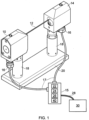
- the apparatus comprises a transmitter 10 for generating a substantially collimated beam of light 12.
- the transmitter 10 includes a laser diode and suitable optics (not shown) for generating the collimated beam of light 12.
- a receiver 14 is also illustrated for receiving the beam of light 12.
- the receiver comprises a photodiode (not shown) for detecting the beam of light 12.
- the transmitter 10 and receiver 14 are both affixed to a common base 20 by pillars 18. This arrangement ensures the transmitter 10 and receiver 14 maintain a fixed spacing and orientation relative to one another.
- the base 20 may then be mounted directly to the bed, or indeed any appropriate part, of a machine tool.
- various alternative structures for mounting the transmitter and receiver could be used. For example, a common housing for the transmitter and receiver could be provided or discrete transmitter and receiver units could be separately mounted to the machine tool.
- the apparatus also comprises an interface 15 connected to the transmitter 10 and receiver 14 via electrical cables 17.
- the interface 15 provides electrical power to the transmitter 10 and receiver 14 and also receives a beam intensity signal from the photodiode detector of the receiver 14.
- the interface 15 also comprises a trigger unit 22 that monitors the beam intensity signal it receives from receiver 14 and issues a trigger signal to an associated machine tool 30 when the beam intensity signal crosses a trigger threshold.
- the trigger signal of this example comprises a change in status of an output line, but it could also be implemented as an electrical pulse or other known way of communicating to the controller of the machine tool 30.
- the interface 15 also comprises a tool length correction unit 40, that is described in more detail below.
- the transmitter 10 and receiver 14 Prior to use in a tool measurement operation, for example during a set-up or installation process, the transmitter 10 and receiver 14 are aligned relative to one another to maximise the intensity of light falling on the photodiode of the receiver 14.
- a variable gain amplifier associated with the receiver is then adjusted so that the beam intensity signal takes a value of 5v in the absence of any blockage of the beam (i.e. with the apparatus in the so-called "beam clear" condition).
- This 5v beam intensity signal is set as a reference beam intensity level.
- the trigger unit 22 is then set to have a fixed trigger threshold of 2.5v (i.e. fifty percent of the reference maximum beam intensity level). Passing an object into the light beam 12 will result in a trigger signal being issued when the beam intensity signal drops below 2.5v.
- This trigger signal can thus be used to indicate that an object (e.g. a tool) has attained a certain position relative to the laser beam 12.
- a 50% level is commonly used, thresholds anywhere in the region of 50% or 2.5V could be used.
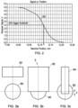
- Figure 2 demonstrates how the issuance of a trigger signal occurs when passing a large, solid (calibration) pin having an 8mm diameter into the light beam which has a beam width of less than 8mm.
- the graph of figure 2 shows the variation in beam intensity signal (plotted on the y-axis) as a function of the position of the pin as measured by the machine tool (plotted on the x-axis) when the calibration pin is traversed into the light beam along a direction perpendicular to the axis of the light beam.
- the absence of any blockage of the light beam i.e.
- the beam intensity signal takes a value of approximately 5v and this reduces to 0v when the beam is fully blocked following an s-shaped curve 50.
- the use of the 2.5v (50%) trigger threshold can be seen to give a trigger position for the pin of 12.117mm.
- the use of a 50% trigger threshold has been found to provide reliable measurements of tool position when the tool is larger than the beam width of the light beam.
- a fixed trigger threshold has been found to introduce errors when the tool diameter is smaller than the beam width.
- Figure 3a shows a light beam 80 generated by the tool setter apparatus described above.
- the light beam 80 is, to a good approximation, circular and has a Gaussian intensity distribution. As mentioned above, the light beam is collimated and thus has a similar cross-section along its length.
- Figure 3a shows the so-called "beam clear" condition in which the tool 82 to be measured is clear of the beam. In this example, 100% of the light passes from the transmitter 10 to the receiver 14.
- the tool 82 is moved into the light beam 80 (along the direction z) by the machine tool.
- the trigger unit 22 issues a trigger signal.
- the machine tool records the measured position of the tool at the instant the trigger signal is received, thereby allowing (with suitable calibration) the position of the tool tip to be determined.
- the measured tool length of tool 82 can thus be stored and subsequently used when that particular tool is being used in a cutting operation.
- FIG 3c the positional error that will arise when using a fixed trigger threshold to measure a tool 84 having a diameter less than the diameter of the light beam 80 is illustrated.
- the tool 84 would be moved (along the direction z) into the light beam 80.
- the tool does not occlude the entire width of the light beam, so the fifty percent trigger condition is not reached when the tool tip reaches the centre of the light beam 80.
- the tool 84 needs to pass further into the beam to the position illustrated in figure 3c before the trigger signal is issued.
- the tip position of the tool 84 is thus offset by the distance E from the beam centre; this extra distance E is interpreted by the machine tool as a reduced length of tool 84 (i.e.
- the machine tool measures the tool 84 to be shorter than it actually is because it needs to be moved further into the beam before the trigger signal is generated). This difference or error between the measured positions of the tips of the tools 82 and 84 results in errors in any parts that are cut using these tools (i.e. because the tool length includes this error).
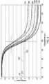
- Figure 4 shows the effect of tool diameter on the beam intensity signal produced as the tool is moved into the light beam.
- the x-axis shows the displacement of the tool relative to the light beam and the y-axis (vertical axis) shows the beam intensity signal in volts.
- Curves 102, 104, 106, 108, 109 and 110 show the drop in the beam intensity signal when tools having nominal diameters of 100 ⁇ m, 70 ⁇ m, 60 ⁇ m, 40 ⁇ m, 30 ⁇ m and 20 ⁇ m respectively are moved into the light beam.
- the beam width is less than 100 ⁇ m, but more than 70 ⁇ m, so only the largest 100 ⁇ m tool will fully obscure the beam when fully inserted into it.
- the 100 ⁇ m tool could be replaced with a calibration pin. If the trigger threshold was set at 2.0v, it can be seen from figure 4 that the measured length of the different diameter tools would include an error L of more than 10 ⁇ m.
- the trigger unit 22 of the tool length correction unit 40 is instructed to adjust the trigger threshold to remove (or at least reduce) the positional error that is described above.
- the tool length correction unit 40 stores a beam width value and receives nominal tool diameter information from the machine tool 30 relating to the tool to be measured. Prior to measurement of the tool, the tool length correction unit 40 checks if the nominal tool diameter is less than the beam width. For any such tools, a mapping operation is performed by the tool length correction unit 40 to determine the trigger threshold voltage that is required for a trigger signal to be issued when the tip of the tool is located at the same point relative to the beam as the calibration pin. This mapping process is based on using a look-up table of corrections (e.g. taken from data of the type shown in figure 4 ) in the present example. However, the look-up table could also be generated by optically modelling the effect of partially obscuring the beam to obtain suitable mathematical expressions etc. that relate the necessary trigger threshold voltage to tool diameter.
- a look-up table of corrections e.g. taken from data
- the tool length correction unit 40 would instruct the trigger unit 22 to issue a trigger signal when the 2.2V threshold is crossed.
- the 70 ⁇ m tool and the 100 ⁇ m tool are both located in the same z-position in the beam when the beam intensity signal is at 2.2V and 2.1V respectively.
- the different trigger thresholds 120 and 122 are crossed with the tool tip located at the same position in the light beam by the 70 ⁇ m tool and the 100 ⁇ m respectively. In this manner, the tool length correction unit 40 compensates for the reduced beam occlusion that occurs when measuring tools having a diameter smaller than the beam width.
- An s-curve is a graphical representation of the detector response as a tool in inserted progressively into the optical beam. The simplest case is for a perfectly aligned tool passing through the centre of the beam.
- the vertical axis of the plot is the detector response (this scale can be in Volts or a percent of the un-obstructed beam response as per figure 5 ) and the horizontal axis is tool displacement, or more conveniently, tip location relative to a desired plane within the optical beam, in units of distance (e.g. microns or millimetres).
- Figure 6 thus illustrates a raw s-curve measurement for a spinning 50 ⁇ m diameter tool in which the alternating current (AC) component is due to the tool flutes.
- AC alternating current
- the raw s-curve can be smoothed by considering just the minima value per revolution of the tool, before extracting calibration data.
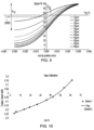
- Figure 7 illustrates a series of smoothed s-curves generated using the minima values extracted as the tool is rotated.
- Curves 300, 302, 304, 306 and 310 relate to tools of diameter 20 ⁇ m, 40 ⁇ m, 60 ⁇ m, 70 ⁇ m and 110 ⁇ m.
- the smoothing process used to generate these s-curves was performed by passing a moving average (5 minima wide) over the minima data to produce the illustrated family of curves.
- FIG 8 it will be explained how offsetting a tool relative to the centre of the light beam has a very similar effect on the s-curves to using tools of different diameters.
- the inset to figure 8 illustrates a tool 404 of diameter d that is moved downwards (i.e. along the z-axis) into a light beam 402 having a beam centre 400.
- the tool 404 has a long axis 406 laterally offset from the beam centre 400 by the distance a.
- the graph of figure 8 shows four overlapping s-curves that are almost indistinguishable from each other.
- this effect is important because it means any calibration data extracted from an s-curve is valid for any tool diameter / tool offset combination which produces that s-curve.
- This means the calibration equation described below which represents extracted data from a series of s-curves thus remains essentially valid for a range of on and off-axis tools.
- a tool length correction relates to the gradient of the s-curve in the region of 75% threshold.
- the tool length correction is expressed as a trigger delay on the vertical axis and s-curve gradient in the region of a 75% threshold (which is dependent on tool diameter) is plotted on the horizontal axis.
- the trigger-delay is plotted as a function of s-curve gradient (in the region of 75% threshold) for tool widths from 10 ⁇ m to 60 ⁇ m (in 5 ⁇ m steps) and for tool lateral-offsets (i.e. distance "a" in figure 8 ) from 0 to 8 ⁇ m (in 1 ⁇ m steps).
- each of the s-curves described above represents the detector response as a tool in inserted progressively into the optical beam.
- the simplest case is a perfectly aligned tool passing through the centre of the beam, but as illustrated in 8, very similar s-curves are produced by different width tools with moderate lateral offsets. This can be highly advantageous from a practical perspective because it greatly relaxes optical alignment constraints for the tool setter apparatus.
- the form of the s-curves and indeed the tolerance of the s-curves to lateral offset will vary somewhat with the geometry of the optical tool-setter due to optical diffraction effects.
- a tool setting apparatus of the type described with reference to figure 1 may have a 55mm long optical beam of 670nm light (light beam 12), passing through a 0.6mm diameter source aperture (i.e. in transmitter 10) and slightly converged to maximise the signal strength entering a receiver aperture of diameter 0.6mm (i.e. in receiver 14).
- the use of such near collimated beams are advantageous for various reasons (e.g. optical cost, resistance to airborne contamination etc) but the same effect would occur in other optical arrangements, such as those that comprise tightly convergent (focussed) or divergent light beams.
- all tool length correction operations occur during a single pass of the tool into the beam.
- the tool length correction would thus be transparent to the user and would externally appear similar to any large-tool measurement operations.
- the s-curve gradient could be determined at, say, a 75% threshold of the unobstructed signal (beam clear) level.
- the offset dz for a 15 ⁇ m tool is labelled Z 15 in figure 5 .
- the value dz or an indication of the gradient at the 75% threshold could be sent directly to the machine controller as a correction, or the trigger signal produced by the non-contact tool setter could be adapted to provide the dz correction (e.g. by altering the trigger threshold or trigger delay).
- the tool may be inserted in the light beam twice.
- the tool In a first measurement step the tool is inserted fully into the light beam (i.e. so it passes from one side of the beam to the other) and the beam intensity signal is measured.
- the beam intensity for such a fully inserted tool is termed the "remnant light level" and this has been found to provide a reliable indication of the tool diameter.
- the reduction in beam intensity from the beam clear value to the remnant light level for the 15 ⁇ m tool is labelled R 15 .
- Figure 10 shows the z-delay or dz value (i.e. the error in tool tip position) for a given beam width as a function of the remnant light level (expressed as a percentage of the beam clear value) for a plurality of tools of different diameter. It can be seen that the relationship follows a curve that can conveniently be described by a low order polynomial.
- the tool may then be withdrawn from the light beam and re-inserted for the second measurement step.
- the second measurement step may simply occur as the tool is withdrawn.
- the tool length correction calculated from the remnant light level may be used to adjust the trigger threshold that is applied during the re-insertion of the tool into the beam. In this manner, the trigger signal issued during the re-insertion may be corrected for the tool diameter being less than the beam width.
- the trigger threshold may simply be set approximately halfway between the beam-clear and remnant light levels for the subsequent measurement (as shown by level 200 in figure 5 ).
- the action of calibration typically involves at least some of the following steps:
- a second optical sensor in this example a camera with a high magnification lens
- a camera was convenient, it should be noted that any suitably accurate displacement sensor could be used.
- a large diameter flat-bottom tool such as an end-mill
- the end-mill was held at "trigger-level” and viewed by the camera. This tells the camera the vertical location of the "large-tool trigger plane”
- the camera axis was set in the desired "depth” (e.g. the large tool trigger) plane perpendicular to the tool motion. It is not essential to set-up the calibration (i.e. Zo) to operate in the large tool trigger plane, but this is a convenient choice for most applications.
- the test was then started by putting a first micro-tool in the spindle of the machine tool.
- the micro-tool was passed into the light beam of the tool setter and using the camera it was observed when the tip is at the "large-tool trigger plane".
- the machine scale value (e.g. termed Z0) was measured at this point.
- the micro-tool was then backed off (i.e. retracted from the light beam) and moved back into the light beam whilst recording both the beam intensity signal and the machine scale (z) values.
- the z-value was also noted at which the beam intensity signal equalled the threshold value (e.g. the 75% threshold); this z-value is the z-offset for this tool.
- the z-offset thus describes the tool length correction that needs to be applied for this particular s-curve (i.e.to account for the tool width being less than the beam width etc).
- the purpose of the tool length correction value i.e. the z-offset
- the particular depth that is used for the correction is selectable and it should be noted that it doesn't have to be the same for all tools. However, for simplicity, a constant depth may be used for all the tools (this is the case for the various embodiments described herein).
- Figure 5 shows a z-offset labelled as Z15, which is the tool-offset at the time the intensity curve for a 15 ⁇ m tool crosses the 75% threshold.
- This Z15 value is thus an example of a "correction value”.
- the Z15 value is a quantity (e.g. a value in micrometers) that could be communicated to the controller to correct its scale readings as recorded at the time of trigger issue.
- each s-curve shown in figure 5 would have a unique tool-offset value.
- Passing information about the tool-offset value (O s ) to the controller of a machine tool is not always possible or practical. Instead, the interface to the machine-tool could be simplified by applying a trigger-delay (i.e. by retarding the issuance of the trigger signal to the machine tool controller) to provide the required tool length correction. It should be noted that such a technique does require the tool feed-rate (V f ) to be known. The required trigger delay (t d ) is then simply the tool-offset (O s ) divided by the feed-rate (V f ); the feed-rate being a known constant (or average) feed-rate value.
- This trigger delay parameter (t d ) allows the tool-setter to issue a trigger to the machine tool at the correct time after the trigger was initially generated (i.e. to implement the tool length correction).
- Another way to implement a tool length correction is to alter the trigger-level (i.e. the threshold level at which trigger signal is issued). This can be done by using the camera to position the tool-tip in the large-tool plane (i.e. at the desired depth). The received signal level then represents the threshold at which, in operation, a trigger is issued to the machine-tool.
- the s-curve feature value may be the modulation depth; i.e. the beam intensity signal when the tool is fully inserted into the beam relative to the beam clear signal.
- the modulation depth can also be termed the maximum obscuration (and may be based on the signal remaining or the signal removed).
- the s-curve feature value may be the gradient in the region of a defined signal level (e.g. the gradient in the region of the trigger threshold) or any other measurement dependent on effective tool width to beam width.
- the feature-value and z-offset value(s) were recorded for this first tool.
- tool-width dependent feature values other than those described above may be used. These may include use of an average gradient, an area under the curve, or the delay between two or more signal levels (for a known (or constant) tool feed-rate).
- the primary purpose of the tool-width dependent feature value is to label or identity which s-curve is being executed. Because the feature value is simply an s-curve identifier, it could also (if required) be replaced by prior knowledge or externally communicated information.
- the test process described above for the first micro-tool was then repeated for a plurality of micro-tools of different diameter.
- the s-curve feature value and z-offsets were thus recorded for all tools in the tool-set. It should be noted that it is not necessary to record (save) the s-curve data; instead, it could be processed in real (or semi-real) time. It is also unnecessary to measure the whole s-curve, it's enough to measure just the s-curve feature value and the correction value (z-offset).
- a correction value e.g. z-offset value
- a simple look-up table could be used.
- a number of methods may be applied. For example, one (albeit crude) approach might be to select the pre-measured value-pair with a feature value closest to the measured feature value. Alternatively, a linear interpolation technique may be used to deduce a modified correction value based on the placement of a measured feature value between its nearest neighbour measured values. The application of cubic splines is also a possibility.
- a correction value is expressed as a function of the feature value using a least-squares fit; this produces what is termed herein a calibration equation.
- the calibration equation for example may describe the correction value as a polynomial series in powers of the feature value.
- a further step was also performed of recording a beam-width parameter (wc) in order to normalise the S-curves and calibration results relative to beam width.
- the normalise correction value was then plotted vertically and the normalised feature-value horizontally.
- a polynomial was then fitted to this data plot using a least-squares routine.
- the fitted polynomial expression is thus the normalised calibration equation.
- the beam-width (wc) that was used during the calibration is also retained as necessary to allow for scaling of the correction value as a function of beam-width when subsequently using the calibration equation.
- a beam width parameter (w) may be measured and an s-curve feature-value is then measured. If necessary, this s-curve is normalised with the beam-width parameter (as described below). Subject to desired accuracy, the resulting calibration equation is valid for a wide variation (e.g. +/- 50%) of beam widths and can then be used to produce a corrected z-offset using the measured beam width parameter (w). It should be noted that if, for example, the tool-setter has limited processor capability, it may be convenient to pre-calculate (i.e.
- a sufficiently large set of value-pairs that are stored in a look-up table may be used to generate the look-up table address.
- This corrected z-offset may then be applied as appropriate (e.g. by altering the trigger threshold, trigger delay etc as described in more detail above).
- the s-curve feature value indicative of effective tool width to beam width yields a calibration equation valid for a range of beam widths.
- normalisation using a first order scaling to account for beam width appears appropriate for beam variations of up to +/- 50%.
- Figure 11 illustrates how diffraction effects lead to only slight deviation from what's expected geometrically for a ⁇ 10% variation in beam and tool width. But the gradients of the curves are different because (on the horizontal axis) the tool has further to travel through a wider beam etc. The s-curves however remain very similar if the units of the horizontal axis are changed from tool-tip position to tool-tip position divided by an indication of the beam width (w).
- Normalised s-curves for calibration are thus plotted with the signal "S" against Z/wc, where Z represents the tip position and wc is an indication of beam width (e.g. 10% to 90% value) at time of calibration. It is then possible to produce a normalised calibration equation (or other) for use in operation. In operation, the normalised feature value would be substituted as a variable into the normalised calibration equation; the feature value being derived in normalised units (Z/s, S) where w is the current value of the beam-width indicator.
- the output of the calibration equation has been defined to relate to the horizontal axis of a normalised s-curve (offset or delay) it would naturally (but not essentially) be expressed in terms of Z/Wc which can be corrected to actual offset (or delay) by multiplying by W.
- a single calibration equation can reliably be applied to a very large number of tool-setter units. If however the feature value is signal level based (e.g. obscuration level) and so too is the correction value (e.g. adjusted trigger level), then normalisation will not be required. Since any compression or expansion of the horizontal axis will have no effect on either value.
- Figure 12 shows a first set of s-curves 600 from ball and 120° tip tools and a second set of s-curves 602 from flat tipped tools.
- the mid fall gradients are very similar, the different geometry tips have different rates of change of gradient in the curved regions.
- An s-curve feature-value in the form of the signal gradient in the curved region of the s-curve could thus be used to differentiate tool-tip. This would allow an s-curve to be identified and the tool length correction then follows in a similar manner to that described above.
- the trigger delay i.e. the time between the trigger threshold being crossed and the issuance of the trigger signal to the machine tool
- the trigger delay could be varied to implement the tool length correction.
- a certain trigger delay could be provided when the tool diameter exceeds the beam width, and this trigger delay could be reduced when the tool diameter is less than the beam width. This effectively advances the trigger signal in time to compensate for the smaller diameter tool.
- the tool length correction could be performed as a separate step after an initial tool length measurement has been made. For example, an uncorrected tool length measurement could be made that ignored the effect of tool diameter.
- a correction value could then be calculated (e.g. using data of the type shown in figure 4 ) that is combined with the uncorrected tool length measurement to generate a corrected tool length.
Landscapes
- Physics & Mathematics (AREA)
- General Physics & Mathematics (AREA)
- Optics & Photonics (AREA)
- Engineering & Computer Science (AREA)
- Mechanical Engineering (AREA)
- Electromagnetism (AREA)
- Machine Tool Sensing Apparatuses (AREA)
- Length Measuring Devices By Optical Means (AREA)
Claims (15)
- Verfahren zur Werkzeuglängenmessung unter Verwendung einer kontaktlosen Werkzeugeinstellvorrichtung, die an einer Werkzeugmaschine angebracht ist, wobei die kontaktlose Werkzeugeinstellvorrichtung einen Sender (10) zum Aussenden eines Lichtstrahls (12; 80), der eine Strahlbreite aufweist, und einen Empfänger (14) zum Empfangen des Lichtstrahls umfasst, wobei der Empfänger ein Strahlintensitätssignal erzeugt, das die Intensität des empfangenen Lichts beschreibt, wobei das Verfahren zum Messen der Länge eines Werkzeugs (84) dient, das einen Nenn-Werkzeugdurchmesser aufweist, der kleiner als die Strahlbreite ist, so dass das vollständige Einführen des Werkzeugs in den Lichtstrahl den Lichtstrahl nur teilweise verdeckt, wobei das Verfahren die Schritte umfasst;(i) Verwenden der Werkzeugmaschine, um das Werkzeug (84) durch den Lichtstrahl (12; 80) zu bewegen, wodurch eine Änderung des Strahlintensitätssignals bewirkt wird, wobei das Werkzeug durch die Werkzeugmaschine in einer Richtung entlang der Länge des Werkzeugs und in einer Richtung senkrecht zur Richtung des Lichtstrahls in den Lichtstrahl hinein oder aus diesem heraus bewegt wird,(ii) Erzeugen eines Auslösesignals, das anzeigt, dass das Strahlintensitätssignal einen Auslöseschwellenwert überschritten hat, und(iii) Bestimmen der Länge des Werkzeugs unter Verwendung des in Schritt (ii) erzeugten Auslösesignals, wobei das Verfahren ferner einen Schritt zum Anwenden einer Werkzeuglängenkorrektur umfasst, die berücksichtigt, dass der Nenn-Werkzeugdurchmesser kleiner als die Strahlbreite ist.
- Verfahren nach Anspruch 1, wobei der Schritt zum Anwenden einer Werkzeuglängenkorrektur ein Einstellen des Auslöseschwellenwerts, der in Schritt (ii) angewendet wird, umfasst, wobei der Auslöseschwellenwert so eingestellt wird, dass der Betrag der Verdeckung des Lichtstrahls, der für eine Erzeugung eines Auslösesignals erforderlich ist, für Werkzeuge mit kleinerem Durchmesser verringert wird.
- Verfahren nach Anspruch 1, wobei Schritt (ii) ein Bereitstellen einer Auslöseverzögerung zwischen dem Überschreiten des Auslöseschwellenwerts und der Ausgabe des Auslösesignals an die Werkzeugmaschine umfasst, wobei der Schritt zum Anwenden einer Werkzeuglängenkorrektur eine Verringerung der Auslöseverzögerung für Werkzeuge mit kleinerem Durchmesser umfasst.
- Verfahren nach einem der Ansprüche 2 oder 3, wobei der Schritt zum Anwenden einer Werkzeuglängenkorrektur bewirkt, dass das Auslösesignal von Schritt (ii) erzeugt wird, wenn sich die Spitzen von Werkzeugen mit unterschiedlichen Werkzeugdurchmessern an im Wesentlichen derselben Position innerhalb des Lichtstrahls befinden.
- Verfahren nach Anspruch 1, wobei Schritt (iii) eine Berechnung einer unkorrigierten Werkzeuglänge umfasst und der Schritt zum Anwenden einer Werkzeuglängenkorrektur eine Anwendung eines Werkzeuglängenkorrekturwertes auf die berechnete unkorrigierte Werkzeuglänge umfasst.
- Verfahren nach einem der vorhergehenden Ansprüche, wobei der Schritt zum Anwenden einer Werkzeuglängenkorrektur eine Berechnung der Werkzeuglängenkorrektur unter Bezugnahme auf eine Kalibrierungsgleichung oder Nachschlagetabelle umfasst, die eine Beziehung zwischen der erforderlichen Werkzeuglängenkorrektur und dem effektiven Werkzeugdurchmesser beschreibt.
- Verfahren nach Anspruch 6, wobei der Schritt zum Anwenden einer Werkzeuglängenkorrektur einen Schritt zum Bewerten des effektiven Werkzeugdurchmessers aus Änderungen im Strahlintensitätssignal umfasst, die auftreten, wenn das Werkzeug durch den Lichtstrahl bewegt wird.
- Verfahren nach Anspruch 7, wobei der Schritt der Bewertung des effektiven Werkzeugdurchmessers eine Messung des Strahlintensitätssignals umfasst, wenn das Werkzeug vollständig in den Lichtstrahl eingeführt ist, wodurch der Lichtstrahl teilweise verdeckt wird.
- Verfahren nach einem der Ansprüche 6 bis 8, umfassend den Schritt zum Ableiten der Kalibrierungsgleichung oder Nachschlagetabelle, die die Beziehung zwischen der erforderlichen Werkzeuglängenkorrektur und dem effektiven Werkzeugdurchmesser beschreibt.
- Verfahren nach Anspruch 9, wobei der Schritt zum Ableiten der Kalibrierungsgleichung oder der Nachschlagetabelle ein Messen der Änderung des Strahlintensitätssignals umfasst, die auftritt, wenn eine Vielzahl von Werkzeugen unterschiedlicher Breite durch den Lichtstrahl bewegt wird.
- Verfahren nach Anspruch 10, wobei der Schritt zum Ableiten der Kalibrierungsgleichung oder der Nachschlagetabelle ein Identifizieren eines auf den effektiven Werkzeugdurchmesser bezogenen Merkmals aus der Änderung des Strahlintensitätssignals umfasst, das auftritt, wenn jedes der Vielzahl von Werkzeugen durch den Lichtstrahl bewegt wird.
- Verfahren nach einem der vorhergehenden Ansprüche, wobei der Schritt zum Anwenden der Werkzeuglängenkorrektur vollständig von der kontaktlosen Werkzeugeinstellvorrichtung durchgeführt wird.
- Verfahren nach einem der vorhergehenden Ansprüche, umfassend den Schritt zum Anwenden einer Einstellung, um jegliche Variation in der Intensität des am Empfänger (14) empfangenen Lichts, wenn sich kein Werkzeug im Lichtstrahl befindet, relativ zu einem Referenzlichtniveau zu berücksichtigen.
- Werkzeugmaschine und kontaktlose Werkzeugeinstellvorrichtung zum Durchführen einer kontaktlosen Werkzeuglängenmessung, wobei die kontaktlose Werkzeugeinstellvorrichtung an der Werkzeugmaschine angebracht ist, wobei die kontaktlose Werkzeugeinstellvorrichtung umfasst:einen Sender (10) zum Aussenden eines Lichtstrahls (12; 80), der eine Strahlbreite aufweist,einen Empfänger (14) zum Empfangen des Lichtstrahls und zum Erzeugen eines Strahlintensitätssignals, das die Intensität des am Empfänger empfangenen Lichts beschreibt, und eineAuslöseeinheit (22) zum Analysieren der Veränderung des Strahlintensitätssignals,wobei die Auslöseeinheit (22) so konfiguriert ist, dass sie ein Auslösesignal erzeugt, wenn das Strahlintensitätssignal einen Auslöseschwellenwert aufgrund dessen überschreitet, dass ein Werkzeug (84), das einen Nenn-Werkzeugdurchmesser aufweist, von der Werkzeugmaschine in einer Richtung entlang der Länge des Werkzeugs und in einer Richtung senkrecht zur Richtung des Lichtstrahls in den Lichtstrahl hinein oder aus diesem heraus bewegt wird, wobei die Werkzeugmaschine so konfiguriert ist, dass sie das Auslösesignal verwendet, um eine Länge des Werkzeugs (84) zu bestimmen, wobei die kontaktlose Werkzeugeinstellvorrichtung eine Werkzeuglängenkorrektureinheit (40) umfasst, die so konfiguriert ist, dass sie eine Werkzeuglängenkorrektur anwendet, wenn der Nenn-Werkzeugdurchmesser kleiner als die Strahlbreite ist.
- Werkzeugmaschine und kontaktlose Werkzeugeinstellvorrichtung nach Anspruch 14, wobei die Werkzeuglängenkorrektureinheit (40) so konfiguriert ist, dass sie die Werkzeuglängenkorrektur anwendet, indem sie den Auslöseschwellenwert der Auslöseeinheit anpasst oder die Ausgabe des Auslösesignals an die Werkzeugmaschine verzögert.
Applications Claiming Priority (2)
| Application Number | Priority Date | Filing Date | Title |
|---|---|---|---|
| EP17189506.3A EP3450097A1 (de) | 2017-09-05 | 2017-09-05 | Otische vorrichtung und optisches verfahren zur kontaktlosen werkzeugeinrichtung |
| PCT/GB2018/052473 WO2019048833A1 (en) | 2017-09-05 | 2018-08-31 | APPARATUS AND METHOD FOR NON-CONTACT OPTICAL MEASUREMENT OF TOOL LENGTH |
Publications (2)
| Publication Number | Publication Date |
|---|---|
| EP3678816A1 EP3678816A1 (de) | 2020-07-15 |
| EP3678816B1 true EP3678816B1 (de) | 2024-03-06 |
Family
ID=59858530
Family Applications (2)
| Application Number | Title | Priority Date | Filing Date |
|---|---|---|---|
| EP17189506.3A Ceased EP3450097A1 (de) | 2017-09-05 | 2017-09-05 | Otische vorrichtung und optisches verfahren zur kontaktlosen werkzeugeinrichtung |
| EP18762126.3A Active EP3678816B1 (de) | 2017-09-05 | 2018-08-31 | Optische vorrichtung und optisches verfahren zur kontaktlosen messung von werkzeuglängen |
Family Applications Before (1)
| Application Number | Title | Priority Date | Filing Date |
|---|---|---|---|
| EP17189506.3A Ceased EP3450097A1 (de) | 2017-09-05 | 2017-09-05 | Otische vorrichtung und optisches verfahren zur kontaktlosen werkzeugeinrichtung |
Country Status (4)
| Country | Link |
|---|---|
| US (1) | US11110563B2 (de) |
| EP (2) | EP3450097A1 (de) |
| JP (1) | JP7422656B2 (de) |
| WO (1) | WO2019048833A1 (de) |
Families Citing this family (2)
| Publication number | Priority date | Publication date | Assignee | Title |
|---|---|---|---|---|
| EP3450936A1 (de) * | 2017-09-05 | 2019-03-06 | Renishaw PLC | Optische vorrichtung und optisches verfahren zur beurteilung des strahlprofils einer kontaktlosen werkzeugeinstellungsvorrichtung |
| CN113695987B (zh) * | 2021-10-11 | 2022-07-12 | 深圳市青鼎装备有限公司 | 直刃型刀具的自动对刀方法 |
Citations (4)
| Publication number | Priority date | Publication date | Assignee | Title |
|---|---|---|---|---|
| US4502823A (en) | 1981-12-21 | 1985-03-05 | Sperry Corporation | Broken drill bit detector |
| US6496273B1 (en) | 1999-05-05 | 2002-12-17 | Renishaw Plc | Position determining apparatus for coordinate positioning machine |
| TW201002469A (en) | 2008-07-09 | 2010-01-16 | Prec Machinery Res & Dev Ct | Optical measuring method and system for tool position |
| DE102013011307A1 (de) | 2013-07-05 | 2015-01-08 | Blum-Novotest Gmbh | Verfahren und Vorrichtung zur Werkzeugmessung oder Werkstückmessung |
Family Cites Families (22)
| Publication number | Priority date | Publication date | Assignee | Title |
|---|---|---|---|---|
| SE376966B (de) | 1973-10-12 | 1975-06-16 | Aga Ab | |
| US4007992A (en) * | 1975-06-02 | 1977-02-15 | Techmet Company | Light beam shape control in optical measuring apparatus |
| US4152767A (en) | 1976-09-27 | 1979-05-01 | Atmospheric Sciences, Inc. | Method and apparatus for measuring dimensions |
| FR2389099A1 (fr) | 1977-04-25 | 1978-11-24 | Sopelem | Procede optique de controle dimensionnel |
| GB8524897D0 (en) * | 1985-10-09 | 1985-11-13 | Veltze J A | Measuring edge of optical image |
| JPH0312106U (de) * | 1989-06-21 | 1991-02-07 | ||
| US5164995A (en) * | 1989-11-27 | 1992-11-17 | General Motors Corporation | Signature analysis apparatus |
| FR2678727A1 (fr) * | 1991-07-04 | 1993-01-08 | Tabacs & Allumettes Ind | Procede et dispositif de calibrage, en particulier de cigarettes, mettant en óoeuvre la determination du temps d'interception d'un faisceau laser. |
| DE4201385A1 (de) * | 1992-01-21 | 1993-07-22 | Peter Dipl Ing Renner | Optisches messsystem |
| US5404022A (en) * | 1993-09-20 | 1995-04-04 | Calcomp Inc. | Automatic roll or cut sheet sensing in plotters |
| US6635894B1 (en) * | 1999-11-22 | 2003-10-21 | Renishaw Plc | Optical measuring apparatus for measuring objects on machines |
| GB0001961D0 (en) * | 2000-01-29 | 2000-03-22 | Renishaw Plc | Position determining apparatus for coordinate positioning machine |
| JP2001277073A (ja) * | 2000-03-30 | 2001-10-09 | Mitsubishi Heavy Ind Ltd | 加工装置の工具位置補正方法 |
| GB0229459D0 (en) | 2002-12-19 | 2003-01-22 | Renishaw Plc | Tool analysis device and method |
| JP2006038487A (ja) * | 2004-07-22 | 2006-02-09 | Mitsutoyo Corp | 光学式測定装置 |
| GB0603653D0 (en) * | 2006-02-24 | 2006-04-05 | Renishaw Plc | Tool detection |
| JP2007301649A (ja) * | 2006-05-09 | 2007-11-22 | Jtekt Corp | 工作機械の工具測定装置 |
| JP4663673B2 (ja) * | 2007-04-16 | 2011-04-06 | 株式会社牧野フライス製作所 | 工具測定方法、及び工具測定機能を備えた工作機械 |
| JP2010249604A (ja) * | 2009-04-14 | 2010-11-04 | Mitsutoyo Corp | 光学式測定装置、光学式測定方法、及び光学式測定処理プログラム |
| DE102017005488A1 (de) * | 2017-06-09 | 2018-12-13 | Blum-Novotest Gmbh | Vorrichtung und Verfahren zum Messen und Kontrollieren eines drehantreibbaren Werkzeugs in einer Werkzeugmaschine |
| EP3450936A1 (de) * | 2017-09-05 | 2019-03-06 | Renishaw PLC | Optische vorrichtung und optisches verfahren zur beurteilung des strahlprofils einer kontaktlosen werkzeugeinstellungsvorrichtung |
| EP3456469A1 (de) * | 2017-09-13 | 2019-03-20 | Renishaw PLC | Vorrichtung und verfahren zur kontaktlosen werkzeugeinrichtung |
-
2017
- 2017-09-05 EP EP17189506.3A patent/EP3450097A1/de not_active Ceased
-
2018
- 2018-08-31 US US16/635,121 patent/US11110563B2/en active Active
- 2018-08-31 WO PCT/GB2018/052473 patent/WO2019048833A1/en not_active Ceased
- 2018-08-31 JP JP2020513499A patent/JP7422656B2/ja active Active
- 2018-08-31 EP EP18762126.3A patent/EP3678816B1/de active Active
Patent Citations (4)
| Publication number | Priority date | Publication date | Assignee | Title |
|---|---|---|---|---|
| US4502823A (en) | 1981-12-21 | 1985-03-05 | Sperry Corporation | Broken drill bit detector |
| US6496273B1 (en) | 1999-05-05 | 2002-12-17 | Renishaw Plc | Position determining apparatus for coordinate positioning machine |
| TW201002469A (en) | 2008-07-09 | 2010-01-16 | Prec Machinery Res & Dev Ct | Optical measuring method and system for tool position |
| DE102013011307A1 (de) | 2013-07-05 | 2015-01-08 | Blum-Novotest Gmbh | Verfahren und Vorrichtung zur Werkzeugmessung oder Werkstückmessung |
Non-Patent Citations (7)
| Title |
|---|
| ANONYMOUS: "BLUM LASERSYSTEME MINI - MICRO - NANO TYPE P87.0634 - Betriebsanleitung Deutsch / Operating Instructions English", BLUM-NOVOTEST GMBH, 15 June 2015 (2015-06-15), XP093246429 |
| ANONYMOUS: "Programmieranleitung - Typ: P87.0634-030.410L I P87.0634-030.4S0L I German Version VSGB", BLUM-NOVOTEST GMBH; LASERCONTROL NT BLUM MESSZYKLEN, vol. 468, no. 8, 1 January 2011 (2011-01-01), pages 134 - 140, XP093246458, DOI: 10.1016/j.cej.2023.143750 |
| ANONYMOUS: "PROGRAMMIERANLEITUNG BLUM MESSZYKLEN (ANWENDER-DOKUMENTATION) P87.0634-030.305 L / VERSION V5D / GERMAN - STEUERUNG: SIEMENS SINUMERIK 840D I 810D LaserControl NT MINI - MICRO - NANO", BLUM-NOVOTEST GMBH, 1 April 2006 (2006-04-01), XP093246434 |
| BLUM ALEXANDER: "Werkzeugvermessung unter rauen Bedingungen", BLUM-NOVOTEST GMBH, XP093246426, Retrieved from the Internet <URL:https://res.cloudinary.com/sternwald-systems/raw/upload/v1/hugoprd/ARTIKEL_ATTACH/0021F83C_C1B5A2AD4A69/53f9228ef397bf155b492d455c817134d056c253/WB_2003_03_Werkzeugvermessung-unter-rauen-Bedingungen.pdf> |
| D10 - Erwiderung Renishaw auf R.161/162 EPÜ Mitteilung vom 16. April 2020 |
| D11 - Synopse Prioritätsdokument P1 vs. A1-Veröffentlichung |
| REISER WOLFGANG: "Praxisorientierte Lasermesstechnik fur die Drehmaschine - Sonderdruck", BLUM NOVOTEST GMBH, 1 February 2004 (2004-02-01), XP093246424 |
Also Published As
| Publication number | Publication date |
|---|---|
| WO2019048833A1 (en) | 2019-03-14 |
| US20200238468A1 (en) | 2020-07-30 |
| EP3450097A1 (de) | 2019-03-06 |
| US11110563B2 (en) | 2021-09-07 |
| EP3678816A1 (de) | 2020-07-15 |
| JP2020532443A (ja) | 2020-11-12 |
| JP7422656B2 (ja) | 2024-01-26 |
Similar Documents
| Publication | Publication Date | Title |
|---|---|---|
| US10775765B2 (en) | Device and method for measuring and controlling a rotary-driven tool in a machine tool | |
| US11400556B2 (en) | Abnormality detection apparatus for working tools | |
| JP4663673B2 (ja) | 工具測定方法、及び工具測定機能を備えた工作機械 | |
| JP7335951B2 (ja) | ワーク処理機械における工具の検査 | |
| JPH03210414A (ja) | 回転する要素の横の変化を測定するための装置 | |
| JP6189191B2 (ja) | 表面形状測定装置および工作機械 | |
| EP3678816B1 (de) | Optische vorrichtung und optisches verfahren zur kontaktlosen messung von werkzeuglängen | |
| JP2019130635A (ja) | 旋削工具および旋削方法 | |
| JP6385338B2 (ja) | 視覚システムの視野内において工作機械の工具を位置決めするための方法、及び、関連する工作機械 | |
| CN104190963A (zh) | 一种基于机器视觉的数控车床对刀装置及对刀方法 | |
| JP3421562B2 (ja) | 刃具の振れ検出方法 | |
| JP5789010B2 (ja) | 表面形状測定装置およびそれを備えた工作機械 | |
| EP3679335B2 (de) | Verfahren zur beurteilung des strahlprofils einer kontaktlosen werkzeugeinstellungsvorrichtung | |
| CN111002103B (zh) | 刀具温度检测系统和刀具温度检测方法 | |
| JP3979891B2 (ja) | 工具測定方法、及び工具測定機能を備えた工作機械 | |
| CN111451838A (zh) | 机床、管理系统及工具劣化检测方法 | |
| JP2001269843A (ja) | 回転工具の中心位置測定方法 | |
| EP4283247B1 (de) | Werkstückdurchmessermessverfahren und werkzeugmaschine | |
| JP2001293642A (ja) | 工具刃先部突出量測定方法及び工具摩耗量測定方法並びにその測定方法を用いた数値制御工作機械 | |
| US20120238184A1 (en) | Method for providing an edge preparation on a cutting edge of a tool and a control and a processing machine for carrying out the method | |
| JPH065853U (ja) | 工具破損検出装置 | |
| JP2000210841A (ja) | 自動切削装置 | |
| WO2024014335A1 (ja) | 異常判定装置、レーザ加工機、及び異常判定方法 | |
| JPS6031617B2 (ja) | 工作機械の寸法制御方法 | |
| JPH0698555B2 (ja) | 試料の表面または境界面を検出する装置 |
Legal Events
| Date | Code | Title | Description |
|---|---|---|---|
| STAA | Information on the status of an ep patent application or granted ep patent |
Free format text: STATUS: UNKNOWN |
|
| STAA | Information on the status of an ep patent application or granted ep patent |
Free format text: STATUS: THE INTERNATIONAL PUBLICATION HAS BEEN MADE |
|
| PUAI | Public reference made under article 153(3) epc to a published international application that has entered the european phase |
Free format text: ORIGINAL CODE: 0009012 |
|
| STAA | Information on the status of an ep patent application or granted ep patent |
Free format text: STATUS: REQUEST FOR EXAMINATION WAS MADE |
|
| 17P | Request for examination filed |
Effective date: 20200317 |
|
| AK | Designated contracting states |
Kind code of ref document: A1 Designated state(s): AL AT BE BG CH CY CZ DE DK EE ES FI FR GB GR HR HU IE IS IT LI LT LU LV MC MK MT NL NO PL PT RO RS SE SI SK SM TR |
|
| AX | Request for extension of the european patent |
Extension state: BA ME |
|
| DAV | Request for validation of the european patent (deleted) | ||
| DAX | Request for extension of the european patent (deleted) | ||
| STAA | Information on the status of an ep patent application or granted ep patent |
Free format text: STATUS: EXAMINATION IS IN PROGRESS |
|
| 17Q | First examination report despatched |
Effective date: 20220413 |
|
| GRAP | Despatch of communication of intention to grant a patent |
Free format text: ORIGINAL CODE: EPIDOSNIGR1 |
|
| STAA | Information on the status of an ep patent application or granted ep patent |
Free format text: STATUS: GRANT OF PATENT IS INTENDED |
|
| INTG | Intention to grant announced |
Effective date: 20230927 |
|
| GRAS | Grant fee paid |
Free format text: ORIGINAL CODE: EPIDOSNIGR3 |
|
| GRAA | (expected) grant |
Free format text: ORIGINAL CODE: 0009210 |
|
| STAA | Information on the status of an ep patent application or granted ep patent |
Free format text: STATUS: THE PATENT HAS BEEN GRANTED |
|
| AK | Designated contracting states |
Kind code of ref document: B1 Designated state(s): AL AT BE BG CH CY CZ DE DK EE ES FI FR GB GR HR HU IE IS IT LI LT LU LV MC MK MT NL NO PL PT RO RS SE SI SK SM TR |
|
| REG | Reference to a national code |
Ref country code: GB Ref legal event code: FG4D |
|
| REG | Reference to a national code |
Ref country code: CH Ref legal event code: EP |
|
| REG | Reference to a national code |
Ref country code: IE Ref legal event code: FG4D |
|
| REG | Reference to a national code |
Ref country code: DE Ref legal event code: R096 Ref document number: 602018066242 Country of ref document: DE |
|
| REG | Reference to a national code |
Ref country code: LT Ref legal event code: MG9D |
|
| PG25 | Lapsed in a contracting state [announced via postgrant information from national office to epo] |
Ref country code: LT Free format text: LAPSE BECAUSE OF FAILURE TO SUBMIT A TRANSLATION OF THE DESCRIPTION OR TO PAY THE FEE WITHIN THE PRESCRIBED TIME-LIMIT Effective date: 20240306 |
|
| REG | Reference to a national code |
Ref country code: NL Ref legal event code: MP Effective date: 20240306 |
|
| PG25 | Lapsed in a contracting state [announced via postgrant information from national office to epo] |
Ref country code: GR Free format text: LAPSE BECAUSE OF FAILURE TO SUBMIT A TRANSLATION OF THE DESCRIPTION OR TO PAY THE FEE WITHIN THE PRESCRIBED TIME-LIMIT Effective date: 20240607 |
|
| PG25 | Lapsed in a contracting state [announced via postgrant information from national office to epo] |
Ref country code: HR Free format text: LAPSE BECAUSE OF FAILURE TO SUBMIT A TRANSLATION OF THE DESCRIPTION OR TO PAY THE FEE WITHIN THE PRESCRIBED TIME-LIMIT Effective date: 20240306 Ref country code: RS Free format text: LAPSE BECAUSE OF FAILURE TO SUBMIT A TRANSLATION OF THE DESCRIPTION OR TO PAY THE FEE WITHIN THE PRESCRIBED TIME-LIMIT Effective date: 20240606 |
|
| PG25 | Lapsed in a contracting state [announced via postgrant information from national office to epo] |
Ref country code: ES Free format text: LAPSE BECAUSE OF FAILURE TO SUBMIT A TRANSLATION OF THE DESCRIPTION OR TO PAY THE FEE WITHIN THE PRESCRIBED TIME-LIMIT Effective date: 20240306 |
|
| PG25 | Lapsed in a contracting state [announced via postgrant information from national office to epo] |
Ref country code: RS Free format text: LAPSE BECAUSE OF FAILURE TO SUBMIT A TRANSLATION OF THE DESCRIPTION OR TO PAY THE FEE WITHIN THE PRESCRIBED TIME-LIMIT Effective date: 20240606 Ref country code: NO Free format text: LAPSE BECAUSE OF FAILURE TO SUBMIT A TRANSLATION OF THE DESCRIPTION OR TO PAY THE FEE WITHIN THE PRESCRIBED TIME-LIMIT Effective date: 20240606 Ref country code: LT Free format text: LAPSE BECAUSE OF FAILURE TO SUBMIT A TRANSLATION OF THE DESCRIPTION OR TO PAY THE FEE WITHIN THE PRESCRIBED TIME-LIMIT Effective date: 20240306 Ref country code: HR Free format text: LAPSE BECAUSE OF FAILURE TO SUBMIT A TRANSLATION OF THE DESCRIPTION OR TO PAY THE FEE WITHIN THE PRESCRIBED TIME-LIMIT Effective date: 20240306 Ref country code: GR Free format text: LAPSE BECAUSE OF FAILURE TO SUBMIT A TRANSLATION OF THE DESCRIPTION OR TO PAY THE FEE WITHIN THE PRESCRIBED TIME-LIMIT Effective date: 20240607 Ref country code: FI Free format text: LAPSE BECAUSE OF FAILURE TO SUBMIT A TRANSLATION OF THE DESCRIPTION OR TO PAY THE FEE WITHIN THE PRESCRIBED TIME-LIMIT Effective date: 20240306 Ref country code: ES Free format text: LAPSE BECAUSE OF FAILURE TO SUBMIT A TRANSLATION OF THE DESCRIPTION OR TO PAY THE FEE WITHIN THE PRESCRIBED TIME-LIMIT Effective date: 20240306 Ref country code: BG Free format text: LAPSE BECAUSE OF FAILURE TO SUBMIT A TRANSLATION OF THE DESCRIPTION OR TO PAY THE FEE WITHIN THE PRESCRIBED TIME-LIMIT Effective date: 20240306 |
|
| REG | Reference to a national code |
Ref country code: AT Ref legal event code: MK05 Ref document number: 1663020 Country of ref document: AT Kind code of ref document: T Effective date: 20240306 |
|
| PG25 | Lapsed in a contracting state [announced via postgrant information from national office to epo] |
Ref country code: SE Free format text: LAPSE BECAUSE OF FAILURE TO SUBMIT A TRANSLATION OF THE DESCRIPTION OR TO PAY THE FEE WITHIN THE PRESCRIBED TIME-LIMIT Effective date: 20240306 Ref country code: LV Free format text: LAPSE BECAUSE OF FAILURE TO SUBMIT A TRANSLATION OF THE DESCRIPTION OR TO PAY THE FEE WITHIN THE PRESCRIBED TIME-LIMIT Effective date: 20240306 |
|
| PG25 | Lapsed in a contracting state [announced via postgrant information from national office to epo] |
Ref country code: NL Free format text: LAPSE BECAUSE OF FAILURE TO SUBMIT A TRANSLATION OF THE DESCRIPTION OR TO PAY THE FEE WITHIN THE PRESCRIBED TIME-LIMIT Effective date: 20240306 |
|
| PG25 | Lapsed in a contracting state [announced via postgrant information from national office to epo] |
Ref country code: NL Free format text: LAPSE BECAUSE OF FAILURE TO SUBMIT A TRANSLATION OF THE DESCRIPTION OR TO PAY THE FEE WITHIN THE PRESCRIBED TIME-LIMIT Effective date: 20240306 |
|
| PG25 | Lapsed in a contracting state [announced via postgrant information from national office to epo] |
Ref country code: IS Free format text: LAPSE BECAUSE OF FAILURE TO SUBMIT A TRANSLATION OF THE DESCRIPTION OR TO PAY THE FEE WITHIN THE PRESCRIBED TIME-LIMIT Effective date: 20240706 |
|
| PG25 | Lapsed in a contracting state [announced via postgrant information from national office to epo] |
Ref country code: PT Free format text: LAPSE BECAUSE OF FAILURE TO SUBMIT A TRANSLATION OF THE DESCRIPTION OR TO PAY THE FEE WITHIN THE PRESCRIBED TIME-LIMIT Effective date: 20240708 Ref country code: SM Free format text: LAPSE BECAUSE OF FAILURE TO SUBMIT A TRANSLATION OF THE DESCRIPTION OR TO PAY THE FEE WITHIN THE PRESCRIBED TIME-LIMIT Effective date: 20240306 |
|
| PG25 | Lapsed in a contracting state [announced via postgrant information from national office to epo] |
Ref country code: EE Free format text: LAPSE BECAUSE OF FAILURE TO SUBMIT A TRANSLATION OF THE DESCRIPTION OR TO PAY THE FEE WITHIN THE PRESCRIBED TIME-LIMIT Effective date: 20240306 Ref country code: CZ Free format text: LAPSE BECAUSE OF FAILURE TO SUBMIT A TRANSLATION OF THE DESCRIPTION OR TO PAY THE FEE WITHIN THE PRESCRIBED TIME-LIMIT Effective date: 20240306 |
|
| PG25 | Lapsed in a contracting state [announced via postgrant information from national office to epo] |
Ref country code: AT Free format text: LAPSE BECAUSE OF FAILURE TO SUBMIT A TRANSLATION OF THE DESCRIPTION OR TO PAY THE FEE WITHIN THE PRESCRIBED TIME-LIMIT Effective date: 20240306 |
|
| PG25 | Lapsed in a contracting state [announced via postgrant information from national office to epo] |
Ref country code: PL Free format text: LAPSE BECAUSE OF FAILURE TO SUBMIT A TRANSLATION OF THE DESCRIPTION OR TO PAY THE FEE WITHIN THE PRESCRIBED TIME-LIMIT Effective date: 20240306 |
|
| PG25 | Lapsed in a contracting state [announced via postgrant information from national office to epo] |
Ref country code: SK Free format text: LAPSE BECAUSE OF FAILURE TO SUBMIT A TRANSLATION OF THE DESCRIPTION OR TO PAY THE FEE WITHIN THE PRESCRIBED TIME-LIMIT Effective date: 20240306 |
|
| PG25 | Lapsed in a contracting state [announced via postgrant information from national office to epo] |
Ref country code: SM Free format text: LAPSE BECAUSE OF FAILURE TO SUBMIT A TRANSLATION OF THE DESCRIPTION OR TO PAY THE FEE WITHIN THE PRESCRIBED TIME-LIMIT Effective date: 20240306 Ref country code: SK Free format text: LAPSE BECAUSE OF FAILURE TO SUBMIT A TRANSLATION OF THE DESCRIPTION OR TO PAY THE FEE WITHIN THE PRESCRIBED TIME-LIMIT Effective date: 20240306 Ref country code: RO Free format text: LAPSE BECAUSE OF FAILURE TO SUBMIT A TRANSLATION OF THE DESCRIPTION OR TO PAY THE FEE WITHIN THE PRESCRIBED TIME-LIMIT Effective date: 20240306 Ref country code: PT Free format text: LAPSE BECAUSE OF FAILURE TO SUBMIT A TRANSLATION OF THE DESCRIPTION OR TO PAY THE FEE WITHIN THE PRESCRIBED TIME-LIMIT Effective date: 20240708 Ref country code: PL Free format text: LAPSE BECAUSE OF FAILURE TO SUBMIT A TRANSLATION OF THE DESCRIPTION OR TO PAY THE FEE WITHIN THE PRESCRIBED TIME-LIMIT Effective date: 20240306 Ref country code: IS Free format text: LAPSE BECAUSE OF FAILURE TO SUBMIT A TRANSLATION OF THE DESCRIPTION OR TO PAY THE FEE WITHIN THE PRESCRIBED TIME-LIMIT Effective date: 20240706 Ref country code: EE Free format text: LAPSE BECAUSE OF FAILURE TO SUBMIT A TRANSLATION OF THE DESCRIPTION OR TO PAY THE FEE WITHIN THE PRESCRIBED TIME-LIMIT Effective date: 20240306 Ref country code: CZ Free format text: LAPSE BECAUSE OF FAILURE TO SUBMIT A TRANSLATION OF THE DESCRIPTION OR TO PAY THE FEE WITHIN THE PRESCRIBED TIME-LIMIT Effective date: 20240306 Ref country code: AT Free format text: LAPSE BECAUSE OF FAILURE TO SUBMIT A TRANSLATION OF THE DESCRIPTION OR TO PAY THE FEE WITHIN THE PRESCRIBED TIME-LIMIT Effective date: 20240306 |
|
| REG | Reference to a national code |
Ref country code: DE Ref legal event code: R026 Ref document number: 602018066242 Country of ref document: DE |
|
| PLBI | Opposition filed |
Free format text: ORIGINAL CODE: 0009260 |
|
| PLAX | Notice of opposition and request to file observation + time limit sent |
Free format text: ORIGINAL CODE: EPIDOSNOBS2 |
|
| 26 | Opposition filed |
Opponent name: BLUM-NOVOTEST GMBH Effective date: 20241206 |
|
| PG25 | Lapsed in a contracting state [announced via postgrant information from national office to epo] |
Ref country code: DK Free format text: LAPSE BECAUSE OF FAILURE TO SUBMIT A TRANSLATION OF THE DESCRIPTION OR TO PAY THE FEE WITHIN THE PRESCRIBED TIME-LIMIT Effective date: 20240306 |
|
| PG25 | Lapsed in a contracting state [announced via postgrant information from national office to epo] |
Ref country code: DK Free format text: LAPSE BECAUSE OF FAILURE TO SUBMIT A TRANSLATION OF THE DESCRIPTION OR TO PAY THE FEE WITHIN THE PRESCRIBED TIME-LIMIT Effective date: 20240306 |
|
| REG | Reference to a national code |
Ref country code: CH Ref legal event code: PL |
|
| PLBB | Reply of patent proprietor to notice(s) of opposition received |
Free format text: ORIGINAL CODE: EPIDOSNOBS3 |
|
| PG25 | Lapsed in a contracting state [announced via postgrant information from national office to epo] |
Ref country code: LU Free format text: LAPSE BECAUSE OF NON-PAYMENT OF DUE FEES Effective date: 20240831 |
|
| PG25 | Lapsed in a contracting state [announced via postgrant information from national office to epo] |
Ref country code: MC Free format text: LAPSE BECAUSE OF FAILURE TO SUBMIT A TRANSLATION OF THE DESCRIPTION OR TO PAY THE FEE WITHIN THE PRESCRIBED TIME-LIMIT Effective date: 20240306 Ref country code: SI Free format text: LAPSE BECAUSE OF FAILURE TO SUBMIT A TRANSLATION OF THE DESCRIPTION OR TO PAY THE FEE WITHIN THE PRESCRIBED TIME-LIMIT Effective date: 20240306 Ref country code: CH Free format text: LAPSE BECAUSE OF NON-PAYMENT OF DUE FEES Effective date: 20240831 |
|
| REG | Reference to a national code |
Ref country code: BE Ref legal event code: MM Effective date: 20240831 |
|
| PG25 | Lapsed in a contracting state [announced via postgrant information from national office to epo] |
Ref country code: BE Free format text: LAPSE BECAUSE OF NON-PAYMENT OF DUE FEES Effective date: 20240831 |
|
| PG25 | Lapsed in a contracting state [announced via postgrant information from national office to epo] |
Ref country code: FR Free format text: LAPSE BECAUSE OF NON-PAYMENT OF DUE FEES Effective date: 20240831 |
|
| PG25 | Lapsed in a contracting state [announced via postgrant information from national office to epo] |
Ref country code: IE Free format text: LAPSE BECAUSE OF NON-PAYMENT OF DUE FEES Effective date: 20240831 |
|
| PGFP | Annual fee paid to national office [announced via postgrant information from national office to epo] |
Ref country code: DE Payment date: 20250827 Year of fee payment: 8 |
|
| PGFP | Annual fee paid to national office [announced via postgrant information from national office to epo] |
Ref country code: IT Payment date: 20250825 Year of fee payment: 8 |
|
| PGFP | Annual fee paid to national office [announced via postgrant information from national office to epo] |
Ref country code: GB Payment date: 20250826 Year of fee payment: 8 |