EP3678284A1 - Motor insulator and brushless motor - Google Patents
Motor insulator and brushless motor Download PDFInfo
- Publication number
- EP3678284A1 EP3678284A1 EP18849955.2A EP18849955A EP3678284A1 EP 3678284 A1 EP3678284 A1 EP 3678284A1 EP 18849955 A EP18849955 A EP 18849955A EP 3678284 A1 EP3678284 A1 EP 3678284A1
- Authority
- EP
- European Patent Office
- Prior art keywords
- winding
- coil
- insulator
- terminal
- guide
- Prior art date
- Legal status (The legal status is an assumption and is not a legal conclusion. Google has not performed a legal analysis and makes no representation as to the accuracy of the status listed.)
- Granted
Links
Images



Classifications
-
- H—ELECTRICITY
- H02—GENERATION; CONVERSION OR DISTRIBUTION OF ELECTRIC POWER
- H02K—DYNAMO-ELECTRIC MACHINES
- H02K3/00—Details of windings
- H02K3/46—Fastening of windings on the stator or rotor structure
- H02K3/52—Fastening salient pole windings or connections thereto
- H02K3/521—Fastening salient pole windings or connections thereto applicable to stators only
- H02K3/522—Fastening salient pole windings or connections thereto applicable to stators only for generally annular cores with salient poles
-
- H—ELECTRICITY
- H02—GENERATION; CONVERSION OR DISTRIBUTION OF ELECTRIC POWER
- H02K—DYNAMO-ELECTRIC MACHINES
- H02K21/00—Synchronous motors having permanent magnets; Synchronous generators having permanent magnets
- H02K21/12—Synchronous motors having permanent magnets; Synchronous generators having permanent magnets with stationary armatures and rotating magnets
- H02K21/14—Synchronous motors having permanent magnets; Synchronous generators having permanent magnets with stationary armatures and rotating magnets with magnets rotating within the armatures
-
- H—ELECTRICITY
- H02—GENERATION; CONVERSION OR DISTRIBUTION OF ELECTRIC POWER
- H02K—DYNAMO-ELECTRIC MACHINES
- H02K2203/00—Specific aspects not provided for in the other groups of this subclass relating to the windings
- H02K2203/12—Machines characterised by the bobbins for supporting the windings
-
- H—ELECTRICITY
- H02—GENERATION; CONVERSION OR DISTRIBUTION OF ELECTRIC POWER
- H02K—DYNAMO-ELECTRIC MACHINES
- H02K3/00—Details of windings
- H02K3/04—Windings characterised by the conductor shape, form or construction, e.g. with bar conductors
- H02K3/28—Layout of windings or of connections between windings
Definitions
- the present invention relates to an insulator for coil insulation mounted to an electric motor and, more particularly, to an insulator used in a brushless motor.
- a stator having a coil wound therearound is disposed in a steel yoke, and a rotor having a magnet is freely rotatably disposed inside the stator.
- an insulator is mounted as a component for insulating between a stator core and a coil, as in Patent Document 1.
- the coil is wound around the tooth part of the stator core through the insulator.
- the coil is wound around each of the tooth part such that the winding-start and winding-end portions thereof are made to pass through between adjacent teeth.
- a crossover wire routed at the back side of the teeth is used to connect coils of the same phase or coils of different phases, whereby one motor winding is formed as a whole.
- crossover wires are arranged at the back side of the teeth.
- the crossover wires densely exist in a narrow space, resulting in wiring congestion.
- coil resistance correspondingly increases.
- a motor insulator is an insulator mounted, for insulation of a coil, to a stator of a motor including the stator provided with the coil wound with a winding and a rotor having a magnet and freely rotatably disposed inside the stator.
- the insulator includes: coil winding parts each wound with the winding; terminal mounting parts each provided radially outward of the coil winding part and each having a coil connection terminal to which the winding is connected; and first guide parts provided radially outward of the coil winding parts not having the terminal mounting part and configured to guide the winding.
- the first guide part has an opening that allows the inside and outside of the first guide part to radially communicate with each other, and the opening is configured with a winding start portion of the coil inserted therethrough.
- an insulator mounted to the stator for insulation of a coil includes coil winding parts each wound with a winding, terminal mounting parts each having a coil connection terminal to which the winding is connected, and first guide parts configured to guide the winding.
- the first guide parts each have an opening for passing therethrough a winding-start portion of the coil.
- the first guide part may be divided into two parts by the opening, and one of the two parts may have a height greater than that of the other one thereof.
- the winding can be arranged at a high position at the higher part, thus allowing the winding to be routed at a higher position than the winding at an adjacent coil winding part.
- the insulator may be mounted to the stator core of the stator, and the terminal mounting part may have an abutting part that abuts against the side surface of the stator core when the insulator is mounted to the stator core.
- the terminal mounting part may have an abutting part that abuts against the side surface of the stator core when the insulator is mounted to the stator core.
- the coil connection terminal may have a hook part to which the winding is locked
- the terminal mounting part may have a wall-like second guide part to which the winding locked to the hook part is hooked.
- tension can be applied to the winding.
- a portion around which the winding is hooked is the wall-like second guide part, so that it is possible to ensure high strength, thus preventing the terminal mounting part from falling down even when tension is applied to the winding. This allows higher tension to be applied to the winding.
- a brushless motor includes: a stator provided with a coil wound with a winding; and a rotor having a magnet and freely rotatably disposed inside the stator.
- the stator has an insulator for insulation of the coil.
- the insulator includes: coil winding parts each wound with the winding; terminal mounting parts each provided radially outward of the coil winding part and each having a coil connection terminal to which the winding is connected; and first guide parts provided radially outward of the coil winding parts not having the terminal mounting part and configured to guide the winding.
- the first guide part has an opening that allows the inside and outside of the first guide part to radially communicate with each other, and the opening is configured with a winding start portion of the coil inserted therethrough.
- an insulator for insulation of a coil is mounted to the stator of a brushless motor. Further, a first guide part configured to guide a winding is provided radially outward of a coil winding part of the insulator, and an opening configured with a winding start portion of the coil inserted therethrough is formed in the first guide part.
- the winding wire that has conventionally been routed to between adjacent teeth along the guide part so as to be wound around a coil winding part therefrom can be introduced to the coil winding part side through the opening.
- the number of windings disposed between the teeth can therefore be reduced to alleviate wiring congestion between the teeth. Further, the length of the winding is reduced, and coil resistance is reduced correspondingly.
- the insulator may be mounted to the stator core of the stator, and the terminal mounting part may have an abutting part that abuts against a side surface of the stator core when the insulator is mounted to the stator core.
- the terminal mounting part may have an abutting part that abuts against a side surface of the stator core when the insulator is mounted to the stator core.
- the insulator mounted to the stator for insulation of a coil includes coil winding parts each wound with a winding, terminal mounting parts each having a coil connection terminal to which the winding is connected, and first guide parts configured to guide the winding, and the first guide parts each have an opening for passing therethrough a winding-start portion of the coil.
- the winding wire that has conventionally been routed to between adj acent teeth along the guide part so as to be wound around a coil winding part therefrom can be introduced to the coil winding part side through the opening.
- the number of windings disposed between the teeth can therefore be reduced to alleviate wiring congestion between the teeth. Further, the length of the winding is reduced, and coil resistance is reduced correspondingly.
- an insulator mounted to the stator of the brushless motor for insulation of a coil includes: coil winding parts each wound with the winding; terminal mounting parts each having a coil connection terminal to which the winding is connected; and first guide parts configured to guide the winding, and an opening configured with a winding start portion of the coil inserted therethrough is formed in the first guide part.
- An object of the embodiment to be described below is to alleviate the congestion of the crossover wires in a brushless motor and shorten the wiring length to thereby reduce coil resistance.
- Another object of the embodiment is to prevent the terminal mounting part from falling down by tension at the time of winding to thereby prevent the terminal from inclining.
- FIG. 1 is an explanatory view illustrating the configuration of a motor unit 1 with speed reduction mechanism using a brushless motor 11 which is an embodiment of the present invention
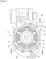
- FIG. 2 is a side view of the brushless motor 11 as viewed in the axial direction thereof.
- the motor unit 1 of FIG. 1 is a motor with speed reduction mechanism having a so-called electromechanically integrated structure in which a motor and a controller are integrated with each other.
- the motor unit 1 includes a motor part 2 having the brushless motor 11, a speed reduction mechanism part 3 using a worm gear, and a control part 4.
- the control part 4 has mounted thereon a control circuit for controlling drive of the brushless motor 11.
- the motor unit 1 is used as, e.g., a drive source of a vehicle electric sunroof.
- the motor part 2 is provided with the brushless motor 11.
- the brushless motor 11 is of an inner-rotor type brushless motor having a stator 12 provided on the outer side and a rotor 13 provided on the inner side.
- the stator 12 has a motor case 14 serving also as a yoke, a stator core (core member) 15 fixed to the inner peripheral side of the motor case 14, and a coil 16 wound around the stator core 15.
- the motor case 14 is made of iron or the like and has a bottomed cylindrical shape, the cross section of which is hexagonal.
- the opening portion of the motor case 14 is attached with a frame 17 made of synthetic resin. The upper portion of the frame 17 is opened, and a cover 18 is attached to the opening portion.
- a flange part 17a of the frame 17 has formed therein a screw hole 17b for attaching the motor.
- a screw 19 is screwed into the screw hole 17b.
- the motor case 14 is fixed to the flange part 17a by the screw 19.
- the stator core 15 has an integrated core structure formed by laminating a large number of steel plates.
- the stator core 15 has a hexagonal yoke part 21 and teeth 22 protruding inward from the yoke part 21.
- a plurality (six here) of the teeth 22 is arranged in the circumferential direction in this example.
- Slots 23 (six here) are formed so as to be each individually located between adjacent teeth 22.
- An insulator 24 made of synthetic resin is fitted inside the stator core 15 from both end sides in the axial direction.
- Each tooth 22 is wound with a winding 25 through the insulator 24 to thereby form a coil 16.
- the insulator 24 is provided with a coil terminal (coil connection terminal) 26 (26U, 26V, 26W) corresponding to each phase (three phases of U, V, W here).
- the coil 16 (winding 25) is electrically connected to each of the coil terminals 26U, 26V and 26W.
- the rotor 13 is disposed inside the stator 12.
- the rotor 13 has a configuration in which a rotary shaft 31, a rotor core 32 and a magnet 33 are coaxially arranged.
- the rotor core 32 has a cylindrical shape formed by laminating a large number of steel plates and is fitted to the outer periphery of the rotary shaft 31.
- the magnet 33 is fixed to the outer periphery of the rotor core 32.
- the magnet 33 is magnetized so as to have a plurality of magnetic poles in the circumferential direction.
- One end portion of the rotary shaft 31 is freely rotatably supported by a bearing 34 press-fitted to the bottom portion of the motor case 14.
- the other end of the rotary shaft 31 is freely rotatably supported by bearing metals 35 and 36 fitted, respectively, to bearing holding parts 17c and 17d of the frame 17.
- a worm 37 is formed on the rotary shaft 31 at the end portion (right end side in FIG. 1 ) thereof.
- the worm 37 mashes with a worm wheel 38 disposed inside the frame 17.
- the worm 37 and worm wheel 38 constitute the speed reduction mechanism part 3.
- the worm wheel 38 is mounted to an output shaft 39.
- rotation of the rotary shaft 31 of the brushless motor 11 is speed-reduced by the speed reduction mechanism part 3 and is transmitted to the output shaft 39, whereby the output shaft 39 is driven into rotation.
- the rotary shaft 31 is fitted with a sensor magnet 41 for detecting rotation of the rotor 13.
- the sensor magnet 41 is magnetized so as to have a plurality of magnetic poles in the circumferential direction.
- a not-shown hall IC magnet detection element
- the hall IC is disposed on a control board 42 of the control part 4.
- the control board 42 has mounted thereon a control IC and elements such as a resistor and a capacitor.
- the control board 42 and brushless motor 11 are electrically connected to each other by an intermediate terminal (board connection terminal) 43 press-fitted into and fixed to a terminal holding part 17e of the frame 17.
- the terminal holding part 17e is disposed at a position axially shifted from the bearing holding part 17c. That is, the terminal holding part 17e and bearing holding part 17c are disposed so as not to axially overlap each other. This allows both the terminal holding part 17e and bearing holding part 17c to be formed into a thick solid shape. As a result, rigidity and durability of the frame 17 are improved, whereby reliability and output power can be increased.
- the insulator 24 is mounted to the stator core 15, and a stator assembly in which the coil 16 is wound/wired is press-fitted into the frame 17.
- the coil terminal 26 (26U, 26V, 26W) of the brushless motor 11 and one end side of the intermediate terminal 43 of each phase are fitted to be electrically connected to each other.
- a load to be applied to the intermediate terminal 43 by the connection of the terminals is received by the terminal holding part 17e.
- the control board 42 is assembled to the frame 17 and then fixed by soldering to the other end side of the intermediate terminal 43.
- the control board 42 and brushless motor 11 are electrically connected, thereby allowing the control part 4 to control drive of the brushless motor 11.
- the insulator 24 according to the present invention has features different from conventional brushless motors in the following points:
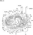
- FIG. 3 is an explanatory view illustrating the configuration of the insulator 24 mounted to the stator core 15.
- the insulator 24 is provided with coil winding parts 51 each wound with the coil 16 and terminal mounting parts 52 each attached with the coil terminal 26.
- the insulator 24 has a function of holding the coil terminals 26 in addition to an insulating function. That is, the brushless motor 11 adopts an "insulator/terminal holder integrated type" configuration.
- each terminal mounting part 52 is formed at the back of the coil winding part 51, i.e., formed radially outward. Further, there are formed guide walls (first guide parts) 53 to 55 at the back of the coil winding parts 51 for which no terminal mounting part 52 is provided.
- a slit-like opening 56 is formed in the center of each of the guide walls 53 to 55.
- the opening 56 allows the inside and outside of each of the guide walls 53 to 55 to radially communicate with each other. Accordingly, each of the guide walls 53 to 55 is divided into two left and right parts (53a and 53b, 54a and 54b, 55a and 55b) by the opening 56.
- a winding 25s which is the winding-start portion of the coil 16 passes.
- the winding 25 is introduced inward through the opening 56 and wound around the coil winding part 51.
- the winding 25 at this portion is routed along the guide wall 53 up to a space between adjacent teeth (X part and Y part in FIG. 3 ) and then wound around the coil winding part 51.
- four windings 25 are arranged in the X part and five windings in the Y part.
- the opening 56 is formed in the center of the guide wall 53, thereby allowing the winding 25s which is the winding-start portion of the coil 16 to be introduced to the coil winding part 51 side through the opening 56.
- the number of windings 25 arranged in the X part is reduced by one to be three
- the number of windings 25 arranged in the Y part is reduced by two to be three, whereby wiring congestion in the X part and Y part can be alleviated, thus facilitating installation of a crossover wire.
- the entire length of the winding 25 is reduced by about half of the lengths of the guide walls 53, that is, by about the lengths of the guide wall 53b, 54b and 55a and, correspondingly, coil resistance can be reduced.
- the guide walls 53 and 55 of the insulator 24 each have different heights on the left and right of the opening 56 (the side closer to the coil terminal 26U is higher) . Specifically, in the guide wall 53, the guide wall 53a is higher than the guide wall 53b. On the other hand, in the guide wall 55, the guide wall 55b is higher than the guide wall 55a.
- a crossover wire 57 of the winding 25 passes on the inner side of the terminal mounting part 52, where the coil 16 also exists.
- the crossover wire 57 is preferably arranged as close to the upper side as possible.
- the guide walls 53 positioned on both sides of the terminal mounting part 52 the guide walls 53a and 55b adjacent to the terminal mounting part 52 are increased in height, and the crossover wire 57 is arranged as close to the upper side as possible.
- Other guide walls 53b and 55a are formed in such a way as to be lower than the guide walls 53a and 55b so that the guide walls 53b and 55a are less apt to fall down by tension of the crossover wire 57 (winding 25).
- a guide protrusion 58 protrudes from the upper portions at both ends of the guide wall 53.
- the crossover wire 57 arranged inside the terminal mounting part 52 is wired at a high position along the guide walls 53a and 55b while being prevented from coming off upward by the guide protrusion 58. That is, the crossover wire 57 is wired so as to be routed obliquely upward from the guide wall 53b side toward the guide wall 53a side and pass immediately below the guide protrusion 58 to be wired on the inner side of the terminal mounting part 52.
- the terminal mounting part 52 is formed high in accordance with the heights of the guide walls 53a and 55b.
- the crossover wire 57 can be wired on the upper side of the coil 16. This makes it possible to avoid interference between the crossover wire 57 and the coil 16 and further to ensure a winding arrangement space at this portion to thereby eliminate wiring congestion.
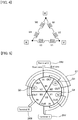
- FIG. 4 is a connection diagram of the coil 16
- FIG. 5 is an explanatory view illustrating the winding state of the coil 16
- FIG. 6 is a winding developed view of the coil 16.
- delta-connection is applied for coil connection, and the coils 16 are connected in a single stroke in which the winding of all slots is completed between start and end wires.
- winding work is performed in the following order with the coil terminal 26U as a start point:
- the winding 25 is locked to a hook part 26a of the coil terminal 26 in a state of being hooked up to a guide wall (second guide part) 59 provided in each terminal mounting part 52, as illustrated in FIG. 7 .
- a guide wall (second guide part) 59 provided in each terminal mounting part 52, as illustrated in FIG. 7 .
- tension can be applied to the winding 25 when the winding 25 is to be hooked up to the hook part 26a.
- a portion around which the winding 25 is hooked is the guide wall 59 integrally formed with the terminal mounting part 52.
- the crossover wire 57 passes over the U1 that has already been wound. Since the coil terminal 26U exists radially outward of the coil U1, the crossover cannot be passed behind the coil terminal 26U. On the other hand, when the crossover pre-exists, it is very difficult to wind the coil U1. In contrast to this, when the winding process as described above is executed, the crossover wire is arranged after the coil is formed, so that the winding work can be performed without any particular trouble. In addition, as described above, the guide walls 53a and 55b are formed high, allowing the crossover wire 57 to pass at a high position, thus making interference with the coil 16 less apt to occur, and this in turn facilitates wiring work.
- the number of overlapping wires can be suppressed to a maximum of four even at the location where the crossover wires 57 overlap.
- the number of overlapping crossover wires 57 is four at the maximum, so that the crossover wires can be easily accommodated and held, and the insulator can be reduced in size and weight.
- FIG. 8 is an explanatory view illustrating the configuration of the terminal mounting part 52 in the insulator 24.
- a terminal insertion hole 61 through which the coil terminal 26 is inserted.
- the coil terminal 26 is inserted into the terminal insertion hole 61 in the direction denoted by arrow P.
- the coil terminal 26 has an engaging claw 62.
- the tip end of the engaging claw 62 is engaged with an upper surface 52a of the terminal mounting part 52, whereby the coil terminal 26 is fixed to the terminal mounting part 52 so as to be prevented from coming off.
- Two rib legs (abutting parts) 63 are provided on the lower side (opposite side of the upper surface 52a) in the drawing of the terminal mounting part 52 so as to extend downward from a terminal mounting part main body 52b.
- Each rib leg 63 is formed in a step-like shape and has a cut part 64.
- the cut part 64 abuts against and fitted to an end edge part 15a of the stator core 15 in a state where the insulator 24 is mounted to the stator core 15.
- an upper surface 64a of the cut part 64 abuts against an edge surface 15b of the stator core 15.
- an inner surface (abutting surface) 64b of the cut part 64 abuts against a side surface 15c of the stator core 15.
- the terminal mounting part 52 when winding is wound on the teeth 22 having the coil terminal 26 at its back side, the terminal mounting part 52 is also applied with a radially outward force by tension at the time of winding and, thus, the terminal mounting part may fall down radially outward.
- the terminal mounting part 52 has the rib leg 63, and the cut part inner surface 64b of the rib leg 63 abuts against the side surface 15c of the stator core 15, so that even when a radially outward force is applied to the terminal mounting part 52, the force can be received by the cut part inner surface 64b.
- the coil terminal 26 is fitted to the intermediate terminal 43 when the brushless motor 11 is assembled to the frame 17 and receives, at this time, a load from the intermediate terminal 43 side.
- the terminal mounting part 52 receives an insertion load of the terminal 43 while being supported on the stator core 15 by the lib leg 63. That is, the terminal mounting part 52 is enhanced in rigidity by the rib leg 63 and thus becomes less likely to be deformed even when receiving the insertion load through the engaging claw 62. As a result, connection work between the coil terminal 26 and the intermediate terminal 43 is facilitated, and damage of the terminal mounting part 52 due to the insertion load is prevented to increase reliability.
- the number of teeth/slots of the brushless motor 11 is merely an example, and the number is not limited to the aforementioned six. Further, there is no problem even if IN/OUT in the winding order is reversed.
- the order of the three-phase UVWs is also arbitrary.
- the counterclockwise order may be U, W and V.
- the number of rib legs 63 of the terminal mounting part 52 is not limited to two, but may be one or three or more.
- the present invention may be widely applicable to, for example, on-vehicle motors used as drive sources for power windows, sliding doors, rear gates and oil pumps; various electric products such as home appliances; and industrial equipment such as robots and electric machines, in addition to the motor for the sunroof.
Landscapes
- Engineering & Computer Science (AREA)
- Power Engineering (AREA)
- Insulation, Fastening Of Motor, Generator Windings (AREA)
- Permanent Magnet Type Synchronous Machine (AREA)
- Windings For Motors And Generators (AREA)
Abstract
Description
- The present invention relates to an insulator for coil insulation mounted to an electric motor and, more particularly, to an insulator used in a brushless motor.
- Generally, in an inner-rotor type brushless motor, a stator having a coil wound therearound is disposed in a steel yoke, and a rotor having a magnet is freely rotatably disposed inside the stator. Further, on the stator side, an insulator is mounted as a component for insulating between a stator core and a coil, as in
Patent Document 1. The coil is wound around the tooth part of the stator core through the insulator. The coil is wound around each of the tooth part such that the winding-start and winding-end portions thereof are made to pass through between adjacent teeth. Then, a crossover wire routed at the back side of the teeth is used to connect coils of the same phase or coils of different phases, whereby one motor winding is formed as a whole. -
- Patent Document 1:
JP 2013-038949 A - Patent Document 2:
JP 2015-133808 A - Patent Document 3:
JP Patent Application No. 2016-005730 - However, in the above-described winding form, a plurality of crossover wires are arranged at the back side of the teeth. As a result, the crossover wires densely exist in a narrow space, resulting in wiring congestion. Further, due to a large number of crossover wires and to a long wiring, coil resistance correspondingly increases.
- On the other hand, in the above insulator, electrical connection is made through a terminal provided at the back side of the teeth. However, in such a structure, when winding is performed on the teeth having the terminal at its back side, a terminal mounting part holding the terminal is applied with a radially outward force by tension generated at the time of winding, causing the terminal mounting part to fall down radially outward, which may disadvantageously incline the terminal.
- A motor insulator according to the present invention is an insulator mounted, for insulation of a coil, to a stator of a motor including the stator provided with the coil wound with a winding and a rotor having a magnet and freely rotatably disposed inside the stator. The insulator includes: coil winding parts each wound with the winding; terminal mounting parts each provided radially outward of the coil winding part and each having a coil connection terminal to which the winding is connected; and first guide parts provided radially outward of the coil winding parts not having the terminal mounting part and configured to guide the winding. The first guide part has an opening that allows the inside and outside of the first guide part to radially communicate with each other, and the opening is configured with a winding start portion of the coil inserted therethrough.
- In the present invention, an insulator mounted to the stator for insulation of a coil includes coil winding parts each wound with a winding, terminal mounting parts each having a coil connection terminal to which the winding is connected, and first guide parts configured to guide the winding. The first guide parts each have an opening for passing therethrough a winding-start portion of the coil. Thus, the winding wire that has conventionally been routed to between adjacent teeth along the guide part so as to be wound around a coil winding part therefrom can be introduced to the coil winding part side through the opening. In this way, the number of windings disposed between the teeth is reduced to alleviate wiring congestion between the teeth. Further, the length of the winding is reduced, and coil resistance is reduced correspondingly.
- In the motor insulator, the first guide part may be divided into two parts by the opening, and one of the two parts may have a height greater than that of the other one thereof. Thus, the winding can be arranged at a high position at the higher part, thus allowing the winding to be routed at a higher position than the winding at an adjacent coil winding part.
- Further, the insulator may be mounted to the stator core of the stator, and the terminal mounting part may have an abutting part that abuts against the side surface of the stator core when the insulator is mounted to the stator core. Thus, even when a radially outward force is applied to the terminal mounting part due to a tension load at the time of winding, the force can be received by the abutting part. Thus, it is possible to prevent the terminal mounting part from falling down radially outward.
- Further, the coil connection terminal may have a hook part to which the winding is locked, and the terminal mounting part may have a wall-like second guide part to which the winding locked to the hook part is hooked. Thus, when the winding is hooked to the hook part, tension can be applied to the winding. In this case, a portion around which the winding is hooked is the wall-like second guide part, so that it is possible to ensure high strength, thus preventing the terminal mounting part from falling down even when tension is applied to the winding. This allows higher tension to be applied to the winding.
- A brushless motor according to the present invention includes: a stator provided with a coil wound with a winding; and a rotor having a magnet and freely rotatably disposed inside the stator. The stator has an insulator for insulation of the coil. The insulator includes: coil winding parts each wound with the winding; terminal mounting parts each provided radially outward of the coil winding part and each having a coil connection terminal to which the winding is connected; and first guide parts provided radially outward of the coil winding parts not having the terminal mounting part and configured to guide the winding. The first guide part has an opening that allows the inside and outside of the first guide part to radially communicate with each other, and the opening is configured with a winding start portion of the coil inserted therethrough.
- In the present invention, an insulator for insulation of a coil is mounted to the stator of a brushless motor. Further, a first guide part configured to guide a winding is provided radially outward of a coil winding part of the insulator, and an opening configured with a winding start portion of the coil inserted therethrough is formed in the first guide part. Thus, the winding wire that has conventionally been routed to between adjacent teeth along the guide part so as to be wound around a coil winding part therefrom can be introduced to the coil winding part side through the opening. The number of windings disposed between the teeth can therefore be reduced to alleviate wiring congestion between the teeth. Further, the length of the winding is reduced, and coil resistance is reduced correspondingly.
- In the brushless motor, the insulator may be mounted to the stator core of the stator, and the terminal mounting part may have an abutting part that abuts against a side surface of the stator core when the insulator is mounted to the stator core. Thus, even when a radially outward force is applied to the terminal mounting part due to a tension load at the time of winding, the force can be received by the abutting part. Thus, it is possible to prevent the terminal mounting part from falling down radially outward.
- According to the motor insulator of the present invention, the insulator mounted to the stator for insulation of a coil includes coil winding parts each wound with a winding, terminal mounting parts each having a coil connection terminal to which the winding is connected, and first guide parts configured to guide the winding, and the first guide parts each have an opening for passing therethrough a winding-start portion of the coil. Thus, the winding wire that has conventionally been routed to between adj acent teeth along the guide part so as to be wound around a coil winding part therefrom can be introduced to the coil winding part side through the opening. The number of windings disposed between the teeth can therefore be reduced to alleviate wiring congestion between the teeth. Further, the length of the winding is reduced, and coil resistance is reduced correspondingly.
- According to the brushless motor of the present invention, an insulator mounted to the stator of the brushless motor for insulation of a coil includes: coil winding parts each wound with the winding; terminal mounting parts each having a coil connection terminal to which the winding is connected; and first guide parts configured to guide the winding, and an opening configured with a winding start portion of the coil inserted therethrough is formed in the first guide part. Thus, the winding wire that has conventionally been routed to between adjacent teeth along the guide part so as to be wound around a coil winding part therefrom can be introduced to the coil winding part side through the opening. The number of windings disposed between the teeth can therefore be reduced to alleviate wiring congestion between the teeth. Further, the length of the winding is reduced, and coil resistance is reduced correspondingly.
-
-
FIG. 1 is an explanatory view illustrating the configuration of a motor unit with speed reduction mechanism using a brushless motor which is an embodiment of the present invention; -
FIG. 2 is a side view of the brushless motor as viewed in the axial direction thereof; -
FIG. 3 is an explanatory view illustrating the configuration of an insulator mounted to a stator core; -
FIG. 4 is a connection diagram of the coil; -
FIG. 5 is an explanatory view illustrating the winding state of the coil; -
FIG. 6 is a winding developed view of the coil; -
FIG. 7 is an explanatory view illustrating a state where the winding is hooked around the guide wall provided in a terminal mounting part of the insulator; and -
FIG. 8 is an explanatory view illustrating the configuration of the terminal mounting part in the insulator. - Hereinafter, an embodiment of the present invention will be described in detail based on the drawings. An object of the embodiment to be described below is to alleviate the congestion of the crossover wires in a brushless motor and shorten the wiring length to thereby reduce coil resistance. Another object of the embodiment is to prevent the terminal mounting part from falling down by tension at the time of winding to thereby prevent the terminal from inclining.
-
FIG. 1 is an explanatory view illustrating the configuration of amotor unit 1 with speed reduction mechanism using abrushless motor 11 which is an embodiment of the present invention, andFIG. 2 is a side view of thebrushless motor 11 as viewed in the axial direction thereof. Themotor unit 1 ofFIG. 1 is a motor with speed reduction mechanism having a so-called electromechanically integrated structure in which a motor and a controller are integrated with each other. Themotor unit 1 includes amotor part 2 having thebrushless motor 11, a speedreduction mechanism part 3 using a worm gear, and acontrol part 4. Thecontrol part 4 has mounted thereon a control circuit for controlling drive of thebrushless motor 11. Themotor unit 1 is used as, e.g., a drive source of a vehicle electric sunroof. - The
motor part 2 is provided with thebrushless motor 11. Thebrushless motor 11 is of an inner-rotor type brushless motor having astator 12 provided on the outer side and arotor 13 provided on the inner side. Thestator 12 has amotor case 14 serving also as a yoke, a stator core (core member) 15 fixed to the inner peripheral side of themotor case 14, and acoil 16 wound around thestator core 15. Themotor case 14 is made of iron or the like and has a bottomed cylindrical shape, the cross section of which is hexagonal. The opening portion of themotor case 14 is attached with aframe 17 made of synthetic resin. The upper portion of theframe 17 is opened, and acover 18 is attached to the opening portion. Aflange part 17a of theframe 17 has formed therein ascrew hole 17b for attaching the motor. Ascrew 19 is screwed into thescrew hole 17b. Themotor case 14 is fixed to theflange part 17a by thescrew 19. - The
stator core 15 has an integrated core structure formed by laminating a large number of steel plates. Thestator core 15 has ahexagonal yoke part 21 andteeth 22 protruding inward from theyoke part 21. A plurality (six here) of theteeth 22 is arranged in the circumferential direction in this example. Slots 23 (six here) are formed so as to be each individually located betweenadjacent teeth 22. Aninsulator 24 made of synthetic resin is fitted inside thestator core 15 from both end sides in the axial direction. Eachtooth 22 is wound with a winding 25 through theinsulator 24 to thereby form acoil 16. Theinsulator 24 is provided with a coil terminal (coil connection terminal) 26 (26U, 26V, 26W) corresponding to each phase (three phases of U, V, W here). The coil 16 (winding 25) is electrically connected to each of thecoil terminals - The
rotor 13 is disposed inside thestator 12. Therotor 13 has a configuration in which arotary shaft 31, arotor core 32 and amagnet 33 are coaxially arranged. Therotor core 32 has a cylindrical shape formed by laminating a large number of steel plates and is fitted to the outer periphery of therotary shaft 31. Themagnet 33 is fixed to the outer periphery of therotor core 32. Themagnet 33 is magnetized so as to have a plurality of magnetic poles in the circumferential direction. One end portion of therotary shaft 31 is freely rotatably supported by a bearing 34 press-fitted to the bottom portion of themotor case 14. The other end of therotary shaft 31 is freely rotatably supported by bearingmetals parts 17c and 17d of theframe 17. - A
worm 37 is formed on therotary shaft 31 at the end portion (right end side inFIG. 1 ) thereof. Theworm 37 mashes with aworm wheel 38 disposed inside theframe 17. Theworm 37 andworm wheel 38 constitute the speedreduction mechanism part 3. Theworm wheel 38 is mounted to anoutput shaft 39. In themotor unit 1, rotation of therotary shaft 31 of thebrushless motor 11 is speed-reduced by the speedreduction mechanism part 3 and is transmitted to theoutput shaft 39, whereby theoutput shaft 39 is driven into rotation. - The
rotary shaft 31 is fitted with asensor magnet 41 for detecting rotation of therotor 13. Thesensor magnet 41 is magnetized so as to have a plurality of magnetic poles in the circumferential direction. A not-shown hall IC (magnetic detection element) is provided in theframe 17 so as to be opposed to the magnetic poles of thesensor magnet 41. The hall IC is disposed on acontrol board 42 of thecontrol part 4. Thecontrol board 42 has mounted thereon a control IC and elements such as a resistor and a capacitor. Thecontrol board 42 andbrushless motor 11 are electrically connected to each other by an intermediate terminal (board connection terminal) 43 press-fitted into and fixed to aterminal holding part 17e of theframe 17. Theterminal holding part 17e is disposed at a position axially shifted from the bearing holding part 17c. That is, theterminal holding part 17e and bearing holding part 17c are disposed so as not to axially overlap each other. This allows both theterminal holding part 17e and bearing holding part 17c to be formed into a thick solid shape. As a result, rigidity and durability of theframe 17 are improved, whereby reliability and output power can be increased. - In the
motor unit 1, theinsulator 24 is mounted to thestator core 15, and a stator assembly in which thecoil 16 is wound/wired is press-fitted into theframe 17. Thus, the coil terminal 26 (26U, 26V, 26W) of thebrushless motor 11 and one end side of theintermediate terminal 43 of each phase are fitted to be electrically connected to each other. At this time, a load to be applied to theintermediate terminal 43 by the connection of the terminals is received by theterminal holding part 17e. After connection of theterminals control board 42 is assembled to theframe 17 and then fixed by soldering to the other end side of theintermediate terminal 43. As a result, thecontrol board 42 andbrushless motor 11 are electrically connected, thereby allowing thecontrol part 4 to control drive of thebrushless motor 11. - The
insulator 24 according to the present invention has features different from conventional brushless motors in the following points: - (1) Winding-start position of coil;
- (2) Winding tension support structure; and
- (3) Falling-down prevention structure for coil terminal mounting part.
- Hereinafter, the above features will be described in order.
-
FIG. 3 is an explanatory view illustrating the configuration of theinsulator 24 mounted to thestator core 15. As illustrated inFIG. 3 , theinsulator 24 is provided withcoil winding parts 51 each wound with thecoil 16 andterminal mounting parts 52 each attached with thecoil terminal 26. Theinsulator 24 has a function of holding thecoil terminals 26 in addition to an insulating function. That is, thebrushless motor 11 adopts an "insulator/terminal holder integrated type" configuration. By thus integrating the insulator and terminal holder, it is unnecessary to assemble electrical connecting components, making it possible to reduce assembling man-hours and the number of components. Further, assembling dimension error of the coil terminal can be reduced. - There are provided three
terminal mounting parts 52, and eachterminal mounting part 52 is formed at the back of thecoil winding part 51, i.e., formed radially outward. Further, there are formed guide walls (first guide parts) 53 to 55 at the back of thecoil winding parts 51 for which noterminal mounting part 52 is provided. By disposing thecoil terminal 26 radially outward of thecoil 16, it is unnecessary for a nozzle for coil winding to perform "operation for avoiding the terminal" at the time of winding thecoil 16. As a result, winding work can be carried out efficiently, and manufacturing man-hours of the stator can be reduced. - In the
insulator 24, a slit-like opening 56 is formed in the center of each of theguide walls 53 to 55. Theopening 56 allows the inside and outside of each of theguide walls 53 to 55 to radially communicate with each other. Accordingly, each of theguide walls 53 to 55 is divided into two left and right parts (53a and 53b, 54a and 54b, 55a and 55b) by theopening 56. Through theopening 56, a winding 25s which is the winding-start portion of thecoil 16 passes. The winding 25 is introduced inward through theopening 56 and wound around thecoil winding part 51. Conventionally, the winding 25 at this portion is routed along theguide wall 53 up to a space between adjacent teeth (X part and Y part inFIG. 3 ) and then wound around thecoil winding part 51. Thus, conventionally, fourwindings 25 are arranged in the X part and five windings in the Y part. - On the other hand, in the
insulator 24 according to the present invention, theopening 56 is formed in the center of theguide wall 53, thereby allowing the winding 25s which is the winding-start portion of thecoil 16 to be introduced to thecoil winding part 51 side through theopening 56. Thus, the number ofwindings 25 arranged in the X part is reduced by one to be three, and the number ofwindings 25 arranged in the Y part is reduced by two to be three, whereby wiring congestion in the X part and Y part can be alleviated, thus facilitating installation of a crossover wire. Further, the entire length of the winding 25 is reduced by about half of the lengths of theguide walls 53, that is, by about the lengths of theguide wall - The
guide walls insulator 24 each have different heights on the left and right of the opening 56 (the side closer to thecoil terminal 26U is higher) . Specifically, in theguide wall 53, theguide wall 53a is higher than theguide wall 53b. On the other hand, in theguide wall 55, theguide wall 55b is higher than theguide wall 55a. - At a portion around the
coil terminal 26U, acrossover wire 57 of the winding 25 passes on the inner side of theterminal mounting part 52, where thecoil 16 also exists. Thus, in order to ensure a space for passing thecrossover wire 57 and to avoid interference between thecrossover wire 57 and thecoil 16, thecrossover wire 57 is preferably arranged as close to the upper side as possible. Thus, in theguide walls 53 positioned on both sides of theterminal mounting part 52, theguide walls terminal mounting part 52 are increased in height, and thecrossover wire 57 is arranged as close to the upper side as possible.Other guide walls guide walls guide walls - A
guide protrusion 58 protrudes from the upper portions at both ends of theguide wall 53. Thecrossover wire 57 arranged inside theterminal mounting part 52 is wired at a high position along theguide walls guide protrusion 58. That is, thecrossover wire 57 is wired so as to be routed obliquely upward from theguide wall 53b side toward theguide wall 53a side and pass immediately below theguide protrusion 58 to be wired on the inner side of theterminal mounting part 52. In this case, theterminal mounting part 52 is formed high in accordance with the heights of theguide walls terminal mounting part 52, thecrossover wire 57 can be wired on the upper side of thecoil 16. This makes it possible to avoid interference between thecrossover wire 57 and thecoil 16 and further to ensure a winding arrangement space at this portion to thereby eliminate wiring congestion. -
FIG. 4 is a connection diagram of thecoil 16,FIG. 5 is an explanatory view illustrating the winding state of thecoil 16, andFIG. 6 is a winding developed view of thecoil 16. As illustrated inFIG. 4 , delta-connection is applied for coil connection, and thecoils 16 are connected in a single stroke in which the winding of all slots is completed between start and end wires. As illustrated inFIGS. 5 and6 , winding work is performed in the following order with thecoil terminal 26U as a start point: - (a) A U-phase first coil U1 is wound from the
coil terminal 26U; - (b) After winding of the U1, a U-phase second coil U2 opposed to the U1 with two
teeth 22 interposed therebetween is wound; - (c) After winding of the U2, the winding is connected from the U2 to the
coil terminal 26V, and a V-phase first coil V1 adjacent to the U2 is wound, and at this time, the winding 25 is drawn through theaforementioned opening 56 of theguide wall 53 for winding of the V1 (Q1 part inFIGS. 3 and5 ); - (d) After winding of the V1, a V-phase second coil V2 opposed to the V1 with two
teeth 22 interposed therebetween is wound and, in this case as well, the winding 25 is drawn through theopening 56 of theguide wall 53 for winding of the V2 (Q2 part inFIGS. 3 and5 ); - (e) After winding of the V2, the winding is connected from the V2 to the
coil terminal 26W, and a W-phase first coil W1 adjacent to the V2 is wound; - (f) After winding of the W1, a W-phase second coil W2 opposed to the W1 with two
teeth 22 interposed therebetween is wound and, in this case as well, the winding 25 is drawn through theopening 56 of theguide wall 53 for winding of the W2 (Q3 part inFIGS. 3 and5 ); and - (g) After winding of the W2, the winding is connected to the
coil terminal 26U adjacent to the W2, and in this case, in the coil W2 which is the end portion of the winding work, the winding-start and winding-end portions are located at the same position so as to maintain the tension of the winding 25. - That is, in the
brushless motor 11, winding is started from a coil terminal existing alone, the opposing coils 16 having the same phase are wound ((b), (d) and (f)), and then adjacent anotherphase coil 16 is wound ((c) and (e)). Thus, the insulator having the terminal holders integrated therewith is assembled to the integrally formedstator core 15, and the winding is delta-connected with a single stroke as described above, so that, in thebrushless motor 11, an assembly process and winding connection process of electrical connecting components become unnecessary. Therefore, the number of manufacturing processes can be reduced to allow cost reduction. - In performing such winding connection, in the
insulator 24, the winding 25 is locked to ahook part 26a of thecoil terminal 26 in a state of being hooked up to a guide wall (second guide part) 59 provided in eachterminal mounting part 52, as illustrated inFIG. 7 . As described above, during the single stroke winding, by hooking the winding 25 along anend part 59a of theguide wall 59, tension can be applied to the winding 25 when the winding 25 is to be hooked up to thehook part 26a. In this case, a portion around which the winding 25 is hooked is theguide wall 59 integrally formed with theterminal mounting part 52. Thus, it is possible to ensure higher strength than a pole or a protrusion, thus preventing theguide wall 59 from falling down even when tension is applied to the winding 25. This allows higher tension to be applied to the winding 25, so that it is possible to increase adhesion between thecoil terminal 26 and winding 25 and thereby to improve electrical connectivity, such as fusing. - Furthermore, in the winding step (d), when the winding 25 is routed from the V1 to V2, the
crossover wire 57 passes over the U1 that has already been wound. Since thecoil terminal 26U exists radially outward of the coil U1, the crossover cannot be passed behind thecoil terminal 26U. On the other hand, when the crossover pre-exists, it is very difficult to wind the coil U1. In contrast to this, when the winding process as described above is executed, the crossover wire is arranged after the coil is formed, so that the winding work can be performed without any particular trouble. In addition, as described above, theguide walls crossover wire 57 to pass at a high position, thus making interference with thecoil 16 less apt to occur, and this in turn facilitates wiring work. - In addition, unlike general single-stroke winding, there is a portion where the crossover wire passes in a string shape above the coil that has been wound, so that the length of the crossover wire can be shortened. In the
other coil terminals crossover wire 57 does not pass behind them but is hooked up to thehook part 26a and then goes to theadjacent coil 16 on thehook part 26a side, there occurs no problem with routing of the crossover wire. - In addition, in the
brushless motor 11, the number of overlapping wires can be suppressed to a maximum of four even at the location where thecrossover wires 57 overlap. In this case, for example, in the motor disclosed inPatent Document 3, there are six overlapping portions of the crossover wires, and the accommodation and handling of the winding 25 becomes complicated. In this respect, in thebrushless motor 11, the number of overlappingcrossover wires 57 is four at the maximum, so that the crossover wires can be easily accommodated and held, and the insulator can be reduced in size and weight. -
FIG. 8 is an explanatory view illustrating the configuration of theterminal mounting part 52 in theinsulator 24. As illustrated inFIG. 8 , there is formed, in theterminal mounting part 52, aterminal insertion hole 61 through which thecoil terminal 26 is inserted. Thecoil terminal 26 is inserted into theterminal insertion hole 61 in the direction denoted by arrow P. Thecoil terminal 26 has an engagingclaw 62. When thecoil terminal 26 is inserted into theterminal insertion hole 61, the tip end of the engagingclaw 62 is engaged with anupper surface 52a of theterminal mounting part 52, whereby thecoil terminal 26 is fixed to theterminal mounting part 52 so as to be prevented from coming off. - Two rib legs (abutting parts) 63 are provided on the lower side (opposite side of the
upper surface 52a) in the drawing of theterminal mounting part 52 so as to extend downward from a terminal mounting partmain body 52b. Eachrib leg 63 is formed in a step-like shape and has acut part 64. Thecut part 64 abuts against and fitted to anend edge part 15a of thestator core 15 in a state where theinsulator 24 is mounted to thestator core 15. As illustrated inFIG. 8 , when theinsulator 24 is mounted to thestator core 15, anupper surface 64a of thecut part 64 abuts against anedge surface 15b of thestator core 15. Further, an inner surface (abutting surface) 64b of thecut part 64 abuts against aside surface 15c of thestator core 15. - As described above, when winding is wound on the
teeth 22 having thecoil terminal 26 at its back side, theterminal mounting part 52 is also applied with a radially outward force by tension at the time of winding and, thus, the terminal mounting part may fall down radially outward. In order to prevent this, in theinsulator 24 according to the present invention, theterminal mounting part 52 has therib leg 63, and the cut part inner surface 64b of therib leg 63 abuts against theside surface 15c of thestator core 15, so that even when a radially outward force is applied to theterminal mounting part 52, the force can be received by the cut part inner surface 64b. Thus, it is possible to suppress the falling down radially outward of theterminal mounting part 52 due to a tension load at the time of winding and to thereby prevent inclination of thecoil terminal 26. - Further, the
coil terminal 26 is fitted to theintermediate terminal 43 when thebrushless motor 11 is assembled to theframe 17 and receives, at this time, a load from theintermediate terminal 43 side. At this time, theterminal mounting part 52 receives an insertion load of the terminal 43 while being supported on thestator core 15 by thelib leg 63. That is, theterminal mounting part 52 is enhanced in rigidity by therib leg 63 and thus becomes less likely to be deformed even when receiving the insertion load through the engagingclaw 62. As a result, connection work between thecoil terminal 26 and theintermediate terminal 43 is facilitated, and damage of theterminal mounting part 52 due to the insertion load is prevented to increase reliability. - The present invention is not limited to the above embodiment, and various modifications may be made without departing from the scope of the invention.
- For example, the number of teeth/slots of the
brushless motor 11 is merely an example, and the number is not limited to the aforementioned six. Further, there is no problem even if IN/OUT in the winding order is reversed. Similarly, the order of the three-phase UVWs is also arbitrary. For example, the counterclockwise order may be U, W and V. Furthermore, the number ofrib legs 63 of theterminal mounting part 52 is not limited to two, but may be one or three or more. When thecoil terminal 26 is provided in theterminal mounting part 52 by insert molding, the entireterminal mounting part 52 may be extended downward to configure the abutting part against theside surface 15c of thestator core 15. - The present invention may be widely applicable to, for example, on-vehicle motors used as drive sources for power windows, sliding doors, rear gates and oil pumps; various electric products such as home appliances; and industrial equipment such as robots and electric machines, in addition to the motor for the sunroof.
-
- 1:
- Motor unit
- 2:
- Motor part
- 3:
- Speed reduction mechanism
- 4:
- Control part
- 11:
- Brushless motor
- 12:
- Stator
- 13:
- Rotor
- 14:
- Motor case
- 15:
- Stator core
- 15a:
- End edge part
- 15b:
- Edge surface
- 15c:
- Side surface
- 16:
- Coil
- 17:
- Frame
- 17a:
- Flange part
- 17b:
- Screw hole
- 17c:
- Bearing holding part
- 17d:
- Bearing holding part
- 17e:
- Terminal holding part
- 18:
- Cover
- 19:
- Screw
- 21:
- Yoke part
- 22:
- Teeth
- 23:
- Slot
- 24:
- Insulator
- 25:
- Winding
- 25s:
- Winding
- 26:
- Coil terminal (coil connection terminal)
- 26U, 26V, 26W:
- Coil terminal
- 26a:
- Hook part
- 31:
- Rotary shaft
- 32:
- Rotor core
- 33:
- Magnet
- 34:
- Bearing
- 35:
- Bearing metal
- 36:
- Bearing metal
- 37:
- Worm
- 38:
- Worm wheel
- 39:
- Output shaft
- 41:
- Sensor magnet
- 42:
- Control board
- 43:
- Intermediate terminal
- 51:
- Coil winding part
- 52:
- Terminal mounting part
- 52a:
- Upper surface
- 52b:
- Main body
- 53:
- Guide wall (first guide part)
- 53a, 53b:
- Guide wall
- 54:
- Guide wall
- 54a, 54b:
- Guide wall
- 55:
- Guide wall
- 55a, 55b:
- Guide wall
- 56:
- Opening
- 57:
- Crossover wire
- 58:
- Guide protrusion
- 59:
- Guide wall (second guide part)
- 59a:
- End part
- 61:
- Terminal insertion hole
- 62:
- Engaging claw
- 63:
- Rib leg
- 64:
- Cut part
- 64a:
- Upper surface
- 64b:
- Inner surface
- U1:
- U-phase first coil
- U2:
- U-phase second coil
- V1:
- V-phase first coil
- V2:
- V-phase second coil
- W1:
- W-phase first coil
- W2:
- W-phase second coil
Claims (6)
- A motor insulator mounted, for insulation of a coil, to a stator of a motor including the stator provided with the coil wound with a winding and a rotor having a magnet and freely rotatably disposed inside the stator,
the insulator being characterized by comprising:coil winding parts each wound with the winding;terminal mounting parts each provided radially outward of the coil winding part and each having a coil connection terminal to which the winding is connected; andfirst guide parts provided radially outward of the coil winding parts not having the terminal mounting part and configured to guide the winding, whereinthe first guide part has an opening that allows the inside and outside of the first guide part to radially communicate with each other, andthe opening is configured with a winding start portion of the coil inserted therethrough. - The motor insulator according to claim 1, characterized in that
the first guide part is divided into two parts by the opening, and
one of the two parts has a height higher than the other one thereof. - The motor insulator according to claim 1 or 2, characterized in that
the insulator is mounted to a stator core of the stator, and
the terminal mounting part has an abutting part that abuts against a side surface of the stator core when the insulator is mounted to the stator core. - The motor insulator according to any one of claims 1 to 3, characterized in that
the coil connection terminal has a hook part to which the winding is locked, and
the terminal mounting part has a wall-like second guide part to which the winding locked to the hook part is hooked. - A brushless motor characterized by comprising:a stator provided with a coil wound with a winding; anda rotor having a magnet and freely rotatably disposed inside the stator, whereinthe stator has an insulator for insulation of the coil, andthe insulator includes:coil winding parts each wound with the winding;terminal mounting parts each provided radially outward of the coil winding part and each having a coil connection terminal to which the winding is connected; andfirst guide parts provided radially outward of the coil winding parts not having the terminal mounting part and configured to guide the winding,the first guide part has an opening that allows the inside and outside of the first guide part to radially communicate with each other, andthe opening is configured with a winding start portion of the coil inserted therethrough.
- The brushless motor according to claim 5, characterized in that
the insulator is mounted to a stator core of the stator, and
the terminal mounting part has an abutting part that abuts against a side surface of the stator core when the insulator is mounted to the stator core.
Applications Claiming Priority (2)
| Application Number | Priority Date | Filing Date | Title |
|---|---|---|---|
| JP2017164007A JP6994873B2 (en) | 2017-08-29 | 2017-08-29 | Brushless motor |
| PCT/JP2018/029378 WO2019044393A1 (en) | 2017-08-29 | 2018-08-06 | Motor insulator and brushless motor |
Publications (3)
| Publication Number | Publication Date |
|---|---|
| EP3678284A1 true EP3678284A1 (en) | 2020-07-08 |
| EP3678284A4 EP3678284A4 (en) | 2021-05-05 |
| EP3678284B1 EP3678284B1 (en) | 2024-04-03 |
Family
ID=65525592
Family Applications (1)
| Application Number | Title | Priority Date | Filing Date |
|---|---|---|---|
| EP18849955.2A Active EP3678284B1 (en) | 2017-08-29 | 2018-08-06 | Motor insulator and brushless motor |
Country Status (4)
| Country | Link |
|---|---|
| EP (1) | EP3678284B1 (en) |
| JP (1) | JP6994873B2 (en) |
| CN (1) | CN111052554B (en) |
| WO (1) | WO2019044393A1 (en) |
Cited By (1)
| Publication number | Priority date | Publication date | Assignee | Title |
|---|---|---|---|---|
| US12407212B2 (en) | 2019-12-16 | 2025-09-02 | Minebea Mitsumi Inc. | Motor with a motor terminal |
Families Citing this family (6)
| Publication number | Priority date | Publication date | Assignee | Title |
|---|---|---|---|---|
| JP2021044940A (en) * | 2019-09-11 | 2021-03-18 | 株式会社マキタ | Electric work machine |
| CN212627378U (en) * | 2020-05-26 | 2021-02-26 | 广东德昌电机有限公司 | Electric device, brushless direct current motor and stator thereof |
| EP4274065A3 (en) | 2022-01-24 | 2023-11-15 | Techtronic Cordless GP | Electrical interconnector and motor including the same |
| JP7892433B2 (en) | 2022-05-12 | 2026-07-21 | 株式会社ミクニ | Stator coil winding section structure |
| JP7905314B2 (en) * | 2023-03-29 | 2026-08-14 | 株式会社ミツバ | Motor device |
| CN116050306B (en) * | 2023-04-03 | 2023-06-02 | 广东电网有限责任公司珠海供电局 | Power frequency power grid reliability assessment method and system considering offshore wind power frequency division access |
Family Cites Families (13)
| Publication number | Priority date | Publication date | Assignee | Title |
|---|---|---|---|---|
| JP5041200B2 (en) * | 2006-03-30 | 2012-10-03 | アイシン精機株式会社 | Stator core and its split core |
| JP2008167604A (en) * | 2006-12-28 | 2008-07-17 | Ichinomiya Denki:Kk | Stator of inner rotor type molded brushless motor |
| JP5636710B2 (en) * | 2010-03-23 | 2014-12-10 | 日産自動車株式会社 | Insulator for rotating electrical machine and method for manufacturing stator winding structure |
| JP5953672B2 (en) | 2011-08-09 | 2016-07-20 | 日本電産株式会社 | motor |
| JP5920619B2 (en) * | 2012-03-23 | 2016-05-18 | 株式会社デンソー | Method for manufacturing brushless motor |
| JP2015133808A (en) | 2014-01-10 | 2015-07-23 | アスモ株式会社 | Insulator and stator |
| JP2015171239A (en) * | 2014-03-07 | 2015-09-28 | アイシン精機株式会社 | Rotating electric machine stator and rotating electric machine |
| JP2016059208A (en) * | 2014-09-11 | 2016-04-21 | 日立オートモティブシステムズ株式会社 | Electric fluid pump |
| DE102015212821A1 (en) * | 2015-07-09 | 2017-01-12 | Brose Fahrzeugteile GmbH & Co. Kommanditgesellschaft, Würzburg | Stator assembly, rotary electric machine and method of manufacturing a stator assembly |
| CN105071563B (en) * | 2015-07-16 | 2017-07-28 | 博格思众(常州)电机电器有限公司 | The stator of tape insulation support |
| JP2016005730A (en) | 2015-09-15 | 2016-01-14 | 株式会社三共 | Slot machine |
| JP6629078B2 (en) * | 2016-01-15 | 2020-01-15 | 株式会社ミツバ | Motor with reduction mechanism |
| CN105553156B (en) * | 2016-01-22 | 2018-11-13 | 珠海格力电器股份有限公司 | Insulation framework for motor stator and motor stator |
-
2017
- 2017-08-29 JP JP2017164007A patent/JP6994873B2/en active Active
-
2018
- 2018-08-06 CN CN201880055342.XA patent/CN111052554B/en active Active
- 2018-08-06 WO PCT/JP2018/029378 patent/WO2019044393A1/en not_active Ceased
- 2018-08-06 EP EP18849955.2A patent/EP3678284B1/en active Active
Cited By (1)
| Publication number | Priority date | Publication date | Assignee | Title |
|---|---|---|---|---|
| US12407212B2 (en) | 2019-12-16 | 2025-09-02 | Minebea Mitsumi Inc. | Motor with a motor terminal |
Also Published As
| Publication number | Publication date |
|---|---|
| EP3678284B1 (en) | 2024-04-03 |
| CN111052554B (en) | 2022-11-08 |
| CN111052554A (en) | 2020-04-21 |
| WO2019044393A1 (en) | 2019-03-07 |
| EP3678284A4 (en) | 2021-05-05 |
| JP6994873B2 (en) | 2022-01-14 |
| JP2019041549A (en) | 2019-03-14 |
Similar Documents
| Publication | Publication Date | Title |
|---|---|---|
| EP3678284B1 (en) | Motor insulator and brushless motor | |
| EP3404805B1 (en) | Brushless motor and motor with speed reduction mechanism | |
| US10892658B2 (en) | Motor with bus-bar assembly | |
| JP4743167B2 (en) | Terminal module for rotating electric machine and rotating electric machine | |
| JP6058164B2 (en) | Rotating electric machine | |
| CN103107625B (en) | Rotary electric machine and method for manufacturing a stator coil connecting unit | |
| CN101828323B (en) | rotating electrical machine | |
| US7545063B2 (en) | Wire-connection structure of motor | |
| EP2940834B1 (en) | Motor | |
| US20120161569A1 (en) | Electric rotating machine | |
| EP2833520A1 (en) | Stator | |
| CN105359383B (en) | Magnet scattering prevention and holding structure of rotating electric machine | |
| CN107615623A (en) | Bus bar unit and rotating electric machine including the bus bar unit | |
| US12489330B2 (en) | Coil winding portion structure for stator | |
| JP6006937B2 (en) | Brushless motor and method for manufacturing brushless motor | |
| US20190097475A1 (en) | Motor | |
| JP6661238B2 (en) | Brushless motor | |
| JP5387604B2 (en) | Terminal module for rotating electric machine and rotating electric machine | |
| CN203722367U (en) | Rotating electromotor | |
| JP6004708B2 (en) | Three-phase AC motor and electric compressor provided with the same | |
| JP6474283B2 (en) | Brushless motor | |
| KR102325880B1 (en) | Terminal device for driving motor of vehicle | |
| JP2008011663A (en) | Lead wire drawing-out structure for motor | |
| JP2024504191A (en) | Method and apparatus for manufacturing a stator for a brushless DC motor | |
| KR101344286B1 (en) | BLDC Motor and Insulator for BLDC Motor |
Legal Events
| Date | Code | Title | Description |
|---|---|---|---|
| STAA | Information on the status of an ep patent application or granted ep patent |
Free format text: STATUS: THE INTERNATIONAL PUBLICATION HAS BEEN MADE |
|
| PUAI | Public reference made under article 153(3) epc to a published international application that has entered the european phase |
Free format text: ORIGINAL CODE: 0009012 |
|
| STAA | Information on the status of an ep patent application or granted ep patent |
Free format text: STATUS: REQUEST FOR EXAMINATION WAS MADE |
|
| 17P | Request for examination filed |
Effective date: 20200224 |
|
| AK | Designated contracting states |
Kind code of ref document: A1 Designated state(s): AL AT BE BG CH CY CZ DE DK EE ES FI FR GB GR HR HU IE IS IT LI LT LU LV MC MK MT NL NO PL PT RO RS SE SI SK SM TR |
|
| AX | Request for extension of the european patent |
Extension state: BA ME |
|
| DAV | Request for validation of the european patent (deleted) | ||
| DAX | Request for extension of the european patent (deleted) | ||
| A4 | Supplementary search report drawn up and despatched |
Effective date: 20210408 |
|
| RIC1 | Information provided on ipc code assigned before grant |
Ipc: H02K 3/46 20060101AFI20210331BHEP Ipc: H02K 3/04 20060101ALI20210331BHEP Ipc: H02K 3/28 20060101ALI20210331BHEP Ipc: H02K 3/50 20060101ALI20210331BHEP Ipc: H02K 3/52 20060101ALI20210331BHEP Ipc: H02K 21/14 20060101ALI20210331BHEP |
|
| GRAP | Despatch of communication of intention to grant a patent |
Free format text: ORIGINAL CODE: EPIDOSNIGR1 |
|
| STAA | Information on the status of an ep patent application or granted ep patent |
Free format text: STATUS: GRANT OF PATENT IS INTENDED |
|
| INTG | Intention to grant announced |
Effective date: 20231114 |
|
| GRAS | Grant fee paid |
Free format text: ORIGINAL CODE: EPIDOSNIGR3 |
|
| GRAA | (expected) grant |
Free format text: ORIGINAL CODE: 0009210 |
|
| STAA | Information on the status of an ep patent application or granted ep patent |
Free format text: STATUS: THE PATENT HAS BEEN GRANTED |
|
| AK | Designated contracting states |
Kind code of ref document: B1 Designated state(s): AL AT BE BG CH CY CZ DE DK EE ES FI FR GB GR HR HU IE IS IT LI LT LU LV MC MK MT NL NO PL PT RO RS SE SI SK SM TR |
|
| REG | Reference to a national code |
Ref country code: GB Ref legal event code: FG4D |
|
| REG | Reference to a national code |
Ref country code: CH Ref legal event code: EP |
|
| REG | Reference to a national code |
Ref country code: DE Ref legal event code: R096 Ref document number: 602018067637 Country of ref document: DE |
|
| REG | Reference to a national code |
Ref country code: IE Ref legal event code: FG4D |
|
| REG | Reference to a national code |
Ref country code: LT Ref legal event code: MG9D |
|
| REG | Reference to a national code |
Ref country code: NL Ref legal event code: MP Effective date: 20240403 |
|
| REG | Reference to a national code |
Ref country code: AT Ref legal event code: MK05 Ref document number: 1673482 Country of ref document: AT Kind code of ref document: T Effective date: 20240403 |
|
| PG25 | Lapsed in a contracting state [announced via postgrant information from national office to epo] |
Ref country code: NL Free format text: LAPSE BECAUSE OF FAILURE TO SUBMIT A TRANSLATION OF THE DESCRIPTION OR TO PAY THE FEE WITHIN THE PRESCRIBED TIME-LIMIT Effective date: 20240403 |
|
| PG25 | Lapsed in a contracting state [announced via postgrant information from national office to epo] |
Ref country code: NL Free format text: LAPSE BECAUSE OF FAILURE TO SUBMIT A TRANSLATION OF THE DESCRIPTION OR TO PAY THE FEE WITHIN THE PRESCRIBED TIME-LIMIT Effective date: 20240403 |
|
| PG25 | Lapsed in a contracting state [announced via postgrant information from national office to epo] |
Ref country code: IS Free format text: LAPSE BECAUSE OF FAILURE TO SUBMIT A TRANSLATION OF THE DESCRIPTION OR TO PAY THE FEE WITHIN THE PRESCRIBED TIME-LIMIT Effective date: 20240803 |
|
| PG25 | Lapsed in a contracting state [announced via postgrant information from national office to epo] |
Ref country code: BG Free format text: LAPSE BECAUSE OF FAILURE TO SUBMIT A TRANSLATION OF THE DESCRIPTION OR TO PAY THE FEE WITHIN THE PRESCRIBED TIME-LIMIT Effective date: 20240403 |
|
| PG25 | Lapsed in a contracting state [announced via postgrant information from national office to epo] |
Ref country code: FI Free format text: LAPSE BECAUSE OF FAILURE TO SUBMIT A TRANSLATION OF THE DESCRIPTION OR TO PAY THE FEE WITHIN THE PRESCRIBED TIME-LIMIT Effective date: 20240403 Ref country code: HR Free format text: LAPSE BECAUSE OF FAILURE TO SUBMIT A TRANSLATION OF THE DESCRIPTION OR TO PAY THE FEE WITHIN THE PRESCRIBED TIME-LIMIT Effective date: 20240403 |
|
| PG25 | Lapsed in a contracting state [announced via postgrant information from national office to epo] |
Ref country code: GR Free format text: LAPSE BECAUSE OF FAILURE TO SUBMIT A TRANSLATION OF THE DESCRIPTION OR TO PAY THE FEE WITHIN THE PRESCRIBED TIME-LIMIT Effective date: 20240704 |
|
| PG25 | Lapsed in a contracting state [announced via postgrant information from national office to epo] |
Ref country code: PT Free format text: LAPSE BECAUSE OF FAILURE TO SUBMIT A TRANSLATION OF THE DESCRIPTION OR TO PAY THE FEE WITHIN THE PRESCRIBED TIME-LIMIT Effective date: 20240805 |
|
| PG25 | Lapsed in a contracting state [announced via postgrant information from national office to epo] |
Ref country code: ES Free format text: LAPSE BECAUSE OF FAILURE TO SUBMIT A TRANSLATION OF THE DESCRIPTION OR TO PAY THE FEE WITHIN THE PRESCRIBED TIME-LIMIT Effective date: 20240403 |
|
| PG25 | Lapsed in a contracting state [announced via postgrant information from national office to epo] |
Ref country code: CZ Free format text: LAPSE BECAUSE OF FAILURE TO SUBMIT A TRANSLATION OF THE DESCRIPTION OR TO PAY THE FEE WITHIN THE PRESCRIBED TIME-LIMIT Effective date: 20240403 |
|
| PG25 | Lapsed in a contracting state [announced via postgrant information from national office to epo] |
Ref country code: AT Free format text: LAPSE BECAUSE OF FAILURE TO SUBMIT A TRANSLATION OF THE DESCRIPTION OR TO PAY THE FEE WITHIN THE PRESCRIBED TIME-LIMIT Effective date: 20240403 |
|
| PG25 | Lapsed in a contracting state [announced via postgrant information from national office to epo] |
Ref country code: PL Free format text: LAPSE BECAUSE OF FAILURE TO SUBMIT A TRANSLATION OF THE DESCRIPTION OR TO PAY THE FEE WITHIN THE PRESCRIBED TIME-LIMIT Effective date: 20240403 |
|
| PG25 | Lapsed in a contracting state [announced via postgrant information from national office to epo] |
Ref country code: LV Free format text: LAPSE BECAUSE OF FAILURE TO SUBMIT A TRANSLATION OF THE DESCRIPTION OR TO PAY THE FEE WITHIN THE PRESCRIBED TIME-LIMIT Effective date: 20240403 |
|
| PG25 | Lapsed in a contracting state [announced via postgrant information from national office to epo] |
Ref country code: PT Free format text: LAPSE BECAUSE OF FAILURE TO SUBMIT A TRANSLATION OF THE DESCRIPTION OR TO PAY THE FEE WITHIN THE PRESCRIBED TIME-LIMIT Effective date: 20240805 Ref country code: PL Free format text: LAPSE BECAUSE OF FAILURE TO SUBMIT A TRANSLATION OF THE DESCRIPTION OR TO PAY THE FEE WITHIN THE PRESCRIBED TIME-LIMIT Effective date: 20240403 Ref country code: NO Free format text: LAPSE BECAUSE OF FAILURE TO SUBMIT A TRANSLATION OF THE DESCRIPTION OR TO PAY THE FEE WITHIN THE PRESCRIBED TIME-LIMIT Effective date: 20240703 Ref country code: LV Free format text: LAPSE BECAUSE OF FAILURE TO SUBMIT A TRANSLATION OF THE DESCRIPTION OR TO PAY THE FEE WITHIN THE PRESCRIBED TIME-LIMIT Effective date: 20240403 Ref country code: IS Free format text: LAPSE BECAUSE OF FAILURE TO SUBMIT A TRANSLATION OF THE DESCRIPTION OR TO PAY THE FEE WITHIN THE PRESCRIBED TIME-LIMIT Effective date: 20240803 Ref country code: HR Free format text: LAPSE BECAUSE OF FAILURE TO SUBMIT A TRANSLATION OF THE DESCRIPTION OR TO PAY THE FEE WITHIN THE PRESCRIBED TIME-LIMIT Effective date: 20240403 Ref country code: GR Free format text: LAPSE BECAUSE OF FAILURE TO SUBMIT A TRANSLATION OF THE DESCRIPTION OR TO PAY THE FEE WITHIN THE PRESCRIBED TIME-LIMIT Effective date: 20240704 Ref country code: FI Free format text: LAPSE BECAUSE OF FAILURE TO SUBMIT A TRANSLATION OF THE DESCRIPTION OR TO PAY THE FEE WITHIN THE PRESCRIBED TIME-LIMIT Effective date: 20240403 Ref country code: ES Free format text: LAPSE BECAUSE OF FAILURE TO SUBMIT A TRANSLATION OF THE DESCRIPTION OR TO PAY THE FEE WITHIN THE PRESCRIBED TIME-LIMIT Effective date: 20240403 Ref country code: CZ Free format text: LAPSE BECAUSE OF FAILURE TO SUBMIT A TRANSLATION OF THE DESCRIPTION OR TO PAY THE FEE WITHIN THE PRESCRIBED TIME-LIMIT Effective date: 20240403 Ref country code: BG Free format text: LAPSE BECAUSE OF FAILURE TO SUBMIT A TRANSLATION OF THE DESCRIPTION OR TO PAY THE FEE WITHIN THE PRESCRIBED TIME-LIMIT Effective date: 20240403 Ref country code: AT Free format text: LAPSE BECAUSE OF FAILURE TO SUBMIT A TRANSLATION OF THE DESCRIPTION OR TO PAY THE FEE WITHIN THE PRESCRIBED TIME-LIMIT Effective date: 20240403 Ref country code: RS Free format text: LAPSE BECAUSE OF FAILURE TO SUBMIT A TRANSLATION OF THE DESCRIPTION OR TO PAY THE FEE WITHIN THE PRESCRIBED TIME-LIMIT Effective date: 20240703 |
|
| REG | Reference to a national code |
Ref country code: DE Ref legal event code: R097 Ref document number: 602018067637 Country of ref document: DE |
|
| PG25 | Lapsed in a contracting state [announced via postgrant information from national office to epo] |
Ref country code: DK Free format text: LAPSE BECAUSE OF FAILURE TO SUBMIT A TRANSLATION OF THE DESCRIPTION OR TO PAY THE FEE WITHIN THE PRESCRIBED TIME-LIMIT Effective date: 20240403 |
|
| PG25 | Lapsed in a contracting state [announced via postgrant information from national office to epo] |
Ref country code: EE Free format text: LAPSE BECAUSE OF FAILURE TO SUBMIT A TRANSLATION OF THE DESCRIPTION OR TO PAY THE FEE WITHIN THE PRESCRIBED TIME-LIMIT Effective date: 20240403 |
|
| PG25 | Lapsed in a contracting state [announced via postgrant information from national office to epo] |
Ref country code: RO Free format text: LAPSE BECAUSE OF FAILURE TO SUBMIT A TRANSLATION OF THE DESCRIPTION OR TO PAY THE FEE WITHIN THE PRESCRIBED TIME-LIMIT Effective date: 20240403 Ref country code: SK Free format text: LAPSE BECAUSE OF FAILURE TO SUBMIT A TRANSLATION OF THE DESCRIPTION OR TO PAY THE FEE WITHIN THE PRESCRIBED TIME-LIMIT Effective date: 20240403 |
|
| PG25 | Lapsed in a contracting state [announced via postgrant information from national office to epo] |
Ref country code: SM Free format text: LAPSE BECAUSE OF FAILURE TO SUBMIT A TRANSLATION OF THE DESCRIPTION OR TO PAY THE FEE WITHIN THE PRESCRIBED TIME-LIMIT Effective date: 20240403 |
|
| PG25 | Lapsed in a contracting state [announced via postgrant information from national office to epo] |
Ref country code: SM Free format text: LAPSE BECAUSE OF FAILURE TO SUBMIT A TRANSLATION OF THE DESCRIPTION OR TO PAY THE FEE WITHIN THE PRESCRIBED TIME-LIMIT Effective date: 20240403 Ref country code: SK Free format text: LAPSE BECAUSE OF FAILURE TO SUBMIT A TRANSLATION OF THE DESCRIPTION OR TO PAY THE FEE WITHIN THE PRESCRIBED TIME-LIMIT Effective date: 20240403 Ref country code: RO Free format text: LAPSE BECAUSE OF FAILURE TO SUBMIT A TRANSLATION OF THE DESCRIPTION OR TO PAY THE FEE WITHIN THE PRESCRIBED TIME-LIMIT Effective date: 20240403 Ref country code: EE Free format text: LAPSE BECAUSE OF FAILURE TO SUBMIT A TRANSLATION OF THE DESCRIPTION OR TO PAY THE FEE WITHIN THE PRESCRIBED TIME-LIMIT Effective date: 20240403 Ref country code: DK Free format text: LAPSE BECAUSE OF FAILURE TO SUBMIT A TRANSLATION OF THE DESCRIPTION OR TO PAY THE FEE WITHIN THE PRESCRIBED TIME-LIMIT Effective date: 20240403 |
|
| PLBE | No opposition filed within time limit |
Free format text: ORIGINAL CODE: 0009261 |
|
| STAA | Information on the status of an ep patent application or granted ep patent |
Free format text: STATUS: NO OPPOSITION FILED WITHIN TIME LIMIT |
|
| 26N | No opposition filed |
Effective date: 20250106 |
|
| REG | Reference to a national code |
Ref country code: CH Ref legal event code: PL |
|
| PG25 | Lapsed in a contracting state [announced via postgrant information from national office to epo] |
Ref country code: LU Free format text: LAPSE BECAUSE OF NON-PAYMENT OF DUE FEES Effective date: 20240806 |
|
| GBPC | Gb: european patent ceased through non-payment of renewal fee |
Effective date: 20240806 |
|
| PG25 | Lapsed in a contracting state [announced via postgrant information from national office to epo] |
Ref country code: SI Free format text: LAPSE BECAUSE OF FAILURE TO SUBMIT A TRANSLATION OF THE DESCRIPTION OR TO PAY THE FEE WITHIN THE PRESCRIBED TIME-LIMIT Effective date: 20240403 Ref country code: MC Free format text: LAPSE BECAUSE OF FAILURE TO SUBMIT A TRANSLATION OF THE DESCRIPTION OR TO PAY THE FEE WITHIN THE PRESCRIBED TIME-LIMIT Effective date: 20240403 Ref country code: CH Free format text: LAPSE BECAUSE OF NON-PAYMENT OF DUE FEES Effective date: 20240831 |
|
| REG | Reference to a national code |
Ref country code: BE Ref legal event code: MM Effective date: 20240831 |
|
| PG25 | Lapsed in a contracting state [announced via postgrant information from national office to epo] |
Ref country code: GB Free format text: LAPSE BECAUSE OF NON-PAYMENT OF DUE FEES Effective date: 20240806 |
|
| PG25 | Lapsed in a contracting state [announced via postgrant information from national office to epo] |
Ref country code: BE Free format text: LAPSE BECAUSE OF NON-PAYMENT OF DUE FEES Effective date: 20240831 |
|
| PG25 | Lapsed in a contracting state [announced via postgrant information from national office to epo] |
Ref country code: FR Free format text: LAPSE BECAUSE OF NON-PAYMENT OF DUE FEES Effective date: 20240831 |
|
| PG25 | Lapsed in a contracting state [announced via postgrant information from national office to epo] |
Ref country code: IE Free format text: LAPSE BECAUSE OF NON-PAYMENT OF DUE FEES Effective date: 20240806 |
|
| PG25 | Lapsed in a contracting state [announced via postgrant information from national office to epo] |
Ref country code: SE Free format text: LAPSE BECAUSE OF FAILURE TO SUBMIT A TRANSLATION OF THE DESCRIPTION OR TO PAY THE FEE WITHIN THE PRESCRIBED TIME-LIMIT Effective date: 20240403 |
|
| PGFP | Annual fee paid to national office [announced via postgrant information from national office to epo] |
Ref country code: DE Payment date: 20250702 Year of fee payment: 8 |
|
| PG25 | Lapsed in a contracting state [announced via postgrant information from national office to epo] |
Ref country code: CY Free format text: LAPSE BECAUSE OF FAILURE TO SUBMIT A TRANSLATION OF THE DESCRIPTION OR TO PAY THE FEE WITHIN THE PRESCRIBED TIME-LIMIT; INVALID AB INITIO Effective date: 20180806 Ref country code: IT Free format text: LAPSE BECAUSE OF FAILURE TO SUBMIT A TRANSLATION OF THE DESCRIPTION OR TO PAY THE FEE WITHIN THE PRESCRIBED TIME-LIMIT Effective date: 20240403 |
|
| PG25 | Lapsed in a contracting state [announced via postgrant information from national office to epo] |
Ref country code: HU Free format text: LAPSE BECAUSE OF FAILURE TO SUBMIT A TRANSLATION OF THE DESCRIPTION OR TO PAY THE FEE WITHIN THE PRESCRIBED TIME-LIMIT; INVALID AB INITIO Effective date: 20180806 |
|
| PG25 | Lapsed in a contracting state [announced via postgrant information from national office to epo] |
Ref country code: TR Free format text: LAPSE BECAUSE OF FAILURE TO SUBMIT A TRANSLATION OF THE DESCRIPTION OR TO PAY THE FEE WITHIN THE PRESCRIBED TIME-LIMIT Effective date: 20240403 |
|
| PG25 | Lapsed in a contracting state [announced via postgrant information from national office to epo] |
Ref country code: LT Free format text: LAPSE BECAUSE OF FAILURE TO SUBMIT A TRANSLATION OF THE DESCRIPTION OR TO PAY THE FEE WITHIN THE PRESCRIBED TIME-LIMIT Effective date: 20240403 |