EP3677757A1 - Muffler device - Google Patents
Muffler device Download PDFInfo
- Publication number
- EP3677757A1 EP3677757A1 EP18891784.3A EP18891784A EP3677757A1 EP 3677757 A1 EP3677757 A1 EP 3677757A1 EP 18891784 A EP18891784 A EP 18891784A EP 3677757 A1 EP3677757 A1 EP 3677757A1
- Authority
- EP
- European Patent Office
- Prior art keywords
- casing
- pipe
- catalyst device
- top cover
- muffler device
- Prior art date
- Legal status (The legal status is an assumption and is not a legal conclusion. Google has not performed a legal analysis and makes no representation as to the accuracy of the status listed.)
- Granted
Links
Images



Classifications
-
- F—MECHANICAL ENGINEERING; LIGHTING; HEATING; WEAPONS; BLASTING
- F01—MACHINES OR ENGINES IN GENERAL; ENGINE PLANTS IN GENERAL; STEAM ENGINES
- F01N—GAS-FLOW SILENCERS OR EXHAUST APPARATUS FOR MACHINES OR ENGINES IN GENERAL; GAS-FLOW SILENCERS OR EXHAUST APPARATUS FOR INTERNAL-COMBUSTION ENGINES
- F01N1/00—Silencing apparatus characterised by method of silencing
- F01N1/08—Silencing apparatus characterised by method of silencing by reducing exhaust energy by throttling or whirling
- F01N1/084—Silencing apparatus characterised by method of silencing by reducing exhaust energy by throttling or whirling the exhaust gases flowing through the silencer two or more times longitudinally in opposite directions, e.g. using parallel or concentric tubes
-
- F—MECHANICAL ENGINEERING; LIGHTING; HEATING; WEAPONS; BLASTING
- F01—MACHINES OR ENGINES IN GENERAL; ENGINE PLANTS IN GENERAL; STEAM ENGINES
- F01N—GAS-FLOW SILENCERS OR EXHAUST APPARATUS FOR MACHINES OR ENGINES IN GENERAL; GAS-FLOW SILENCERS OR EXHAUST APPARATUS FOR INTERNAL-COMBUSTION ENGINES
- F01N1/00—Silencing apparatus characterised by method of silencing
-
- F—MECHANICAL ENGINEERING; LIGHTING; HEATING; WEAPONS; BLASTING
- F01—MACHINES OR ENGINES IN GENERAL; ENGINE PLANTS IN GENERAL; STEAM ENGINES
- F01N—GAS-FLOW SILENCERS OR EXHAUST APPARATUS FOR MACHINES OR ENGINES IN GENERAL; GAS-FLOW SILENCERS OR EXHAUST APPARATUS FOR INTERNAL-COMBUSTION ENGINES
- F01N1/00—Silencing apparatus characterised by method of silencing
- F01N1/02—Silencing apparatus characterised by method of silencing by using resonance
- F01N1/023—Helmholtz resonators
-
- F—MECHANICAL ENGINEERING; LIGHTING; HEATING; WEAPONS; BLASTING
- F01—MACHINES OR ENGINES IN GENERAL; ENGINE PLANTS IN GENERAL; STEAM ENGINES
- F01N—GAS-FLOW SILENCERS OR EXHAUST APPARATUS FOR MACHINES OR ENGINES IN GENERAL; GAS-FLOW SILENCERS OR EXHAUST APPARATUS FOR INTERNAL-COMBUSTION ENGINES
- F01N1/00—Silencing apparatus characterised by method of silencing
- F01N1/08—Silencing apparatus characterised by method of silencing by reducing exhaust energy by throttling or whirling
-
- F—MECHANICAL ENGINEERING; LIGHTING; HEATING; WEAPONS; BLASTING
- F01—MACHINES OR ENGINES IN GENERAL; ENGINE PLANTS IN GENERAL; STEAM ENGINES
- F01N—GAS-FLOW SILENCERS OR EXHAUST APPARATUS FOR MACHINES OR ENGINES IN GENERAL; GAS-FLOW SILENCERS OR EXHAUST APPARATUS FOR INTERNAL-COMBUSTION ENGINES
- F01N1/00—Silencing apparatus characterised by method of silencing
- F01N1/08—Silencing apparatus characterised by method of silencing by reducing exhaust energy by throttling or whirling
- F01N1/089—Silencing apparatus characterised by method of silencing by reducing exhaust energy by throttling or whirling using two or more expansion chambers in series
-
- F—MECHANICAL ENGINEERING; LIGHTING; HEATING; WEAPONS; BLASTING
- F01—MACHINES OR ENGINES IN GENERAL; ENGINE PLANTS IN GENERAL; STEAM ENGINES
- F01N—GAS-FLOW SILENCERS OR EXHAUST APPARATUS FOR MACHINES OR ENGINES IN GENERAL; GAS-FLOW SILENCERS OR EXHAUST APPARATUS FOR INTERNAL-COMBUSTION ENGINES
- F01N3/00—Exhaust or silencing apparatus having means for purifying, rendering innocuous, or otherwise treating exhaust
- F01N3/08—Exhaust or silencing apparatus having means for purifying, rendering innocuous, or otherwise treating exhaust for rendering innocuous
- F01N3/10—Exhaust or silencing apparatus having means for purifying, rendering innocuous, or otherwise treating exhaust for rendering innocuous by thermal or catalytic conversion of noxious components of exhaust
-
- F—MECHANICAL ENGINEERING; LIGHTING; HEATING; WEAPONS; BLASTING
- F01—MACHINES OR ENGINES IN GENERAL; ENGINE PLANTS IN GENERAL; STEAM ENGINES
- F01N—GAS-FLOW SILENCERS OR EXHAUST APPARATUS FOR MACHINES OR ENGINES IN GENERAL; GAS-FLOW SILENCERS OR EXHAUST APPARATUS FOR INTERNAL-COMBUSTION ENGINES
- F01N1/00—Silencing apparatus characterised by method of silencing
- F01N1/02—Silencing apparatus characterised by method of silencing by using resonance
- F01N1/026—Annular resonance chambers arranged concentrically to an exhaust passage and communicating with it, e.g. via at least one opening in the exhaust passage
-
- F—MECHANICAL ENGINEERING; LIGHTING; HEATING; WEAPONS; BLASTING
- F01—MACHINES OR ENGINES IN GENERAL; ENGINE PLANTS IN GENERAL; STEAM ENGINES
- F01N—GAS-FLOW SILENCERS OR EXHAUST APPARATUS FOR MACHINES OR ENGINES IN GENERAL; GAS-FLOW SILENCERS OR EXHAUST APPARATUS FOR INTERNAL-COMBUSTION ENGINES
- F01N2230/00—Combination of silencers and other devices
- F01N2230/04—Catalytic converters
-
- F—MECHANICAL ENGINEERING; LIGHTING; HEATING; WEAPONS; BLASTING
- F01—MACHINES OR ENGINES IN GENERAL; ENGINE PLANTS IN GENERAL; STEAM ENGINES
- F01N—GAS-FLOW SILENCERS OR EXHAUST APPARATUS FOR MACHINES OR ENGINES IN GENERAL; GAS-FLOW SILENCERS OR EXHAUST APPARATUS FOR INTERNAL-COMBUSTION ENGINES
- F01N2230/00—Combination of silencers and other devices
- F01N2230/06—Spark arresters
-
- F—MECHANICAL ENGINEERING; LIGHTING; HEATING; WEAPONS; BLASTING
- F01—MACHINES OR ENGINES IN GENERAL; ENGINE PLANTS IN GENERAL; STEAM ENGINES
- F01N—GAS-FLOW SILENCERS OR EXHAUST APPARATUS FOR MACHINES OR ENGINES IN GENERAL; GAS-FLOW SILENCERS OR EXHAUST APPARATUS FOR INTERNAL-COMBUSTION ENGINES
- F01N2470/00—Structure or shape of exhaust gas passages, pipes or tubes
- F01N2470/02—Tubes being perforated
-
- F—MECHANICAL ENGINEERING; LIGHTING; HEATING; WEAPONS; BLASTING
- F01—MACHINES OR ENGINES IN GENERAL; ENGINE PLANTS IN GENERAL; STEAM ENGINES
- F01N—GAS-FLOW SILENCERS OR EXHAUST APPARATUS FOR MACHINES OR ENGINES IN GENERAL; GAS-FLOW SILENCERS OR EXHAUST APPARATUS FOR INTERNAL-COMBUSTION ENGINES
- F01N2470/00—Structure or shape of exhaust gas passages, pipes or tubes
- F01N2470/22—Inlet and outlet tubes being positioned on the same side of the apparatus
-
- F—MECHANICAL ENGINEERING; LIGHTING; HEATING; WEAPONS; BLASTING
- F01—MACHINES OR ENGINES IN GENERAL; ENGINE PLANTS IN GENERAL; STEAM ENGINES
- F01N—GAS-FLOW SILENCERS OR EXHAUST APPARATUS FOR MACHINES OR ENGINES IN GENERAL; GAS-FLOW SILENCERS OR EXHAUST APPARATUS FOR INTERNAL-COMBUSTION ENGINES
- F01N2590/00—Exhaust or silencing apparatus adapted to particular use, e.g. for military applications, airplanes, submarines
- F01N2590/06—Exhaust or silencing apparatus adapted to particular use, e.g. for military applications, airplanes, submarines for hand-held tools or portables devices
Definitions
- the present invention relates to a muffler device, and particularly relates to a muffler device that is applied to an engine of a portable generator.
- the muffler device like this, for example, there is conventionally disclosed a technology that includes outer plates, and a cylindrical outer shell that supports the respective outer plates, and reduces exhaust noise by reducing exhaust energy in a muffler (refer to Patent Literature 1, for example).
- Patent Literature 1 Japanese Patent Laid-Open No. 2005-155551
- the above described conventional technology is a technology concerning a muffler device of an engine for a vehicle.
- a generator that drives an engine and generates power by the driving force, and the aforementioned conventional technology cannot be directly applied as the muffler device of the generator like this.
- a portable generator needs to be equipped with a catalyst device to purify NOx, and in addition, the portable generator is required to be lightweight and compact.
- An aspect of the present invention is made in the light of the aforementioned point, and has an object to provide a lightweight and compact muffler device that can be installed in a limited space in an inside of a generator, and can ensure a sufficient capacity.
- an aspect of the present invention is a muffler device of a portable generator, including a casing disposed vertically, wherein end covers provided on a top and a bottom of the casing are each formed in a substantially trapezoidal shape.
- an inner capacity of the casing can be secured to be larger as compared with a case where the end covers are each formed into a planar shape, and rigidity can also be enhanced.
- the size of the muffler device can be made compact, and no extra component is required, so that reduction in manufacturing cost and reduction in weight can be achieved.
- the casing since the casing is disposed vertically, it becomes possible to install the casing even when the installation space is small in the inside of the housing of the generator, and it becomes possible to make the generator compact.
- the end covers are formed of a top cover provided at an upper portion of the casing, and an undercover provided at a lower portion of the casing, and an inclined surface is formed on a top surface of the top cover, and an exhaust pipe and a tail pipe are connected to the inclined surface of the top cover.
- connection portions to the exhaust pipe and the tail pipe on the upper portion of the casing it becomes possible to concentrate the connection portions to the exhaust pipe and the tail pipe on the upper portion of the casing, and maintainability can be improved.
- the above described configuration includes a catalyst device in an inside of the casing, wherein the catalyst device is disposed in a vertical direction.
- a diffuser pipe is disposed between a connection portion of the top cover to the exhaust pipe, and a placement position of the catalyst device, in the inside of the casing.
- the diffuser pipe is disposed between the connection portion to the exhaust pipe, and the placement position of the catalyst device, and therefore, a space in which the exhaust gas flowing into the casing exists before entering the catalyst device can be secured to be wide.
- the high-temperature exhaust gas flowing into the casing from the exhaust pipe is cooled before flowing into the catalyst device, and it becomes possible to prevent the catalyst device from being deteriorated by the high-temperature exhaust gas.
- the diffuser pipe extends over a substantially entire region in an up-down direction of the casing, and an arrester is disposed in a connection portion of the diffuser pipe to the tail pipe.
- the arrester is disposed in the inside of the connection pipe of the diffuser pipe, and therefore, reduction in size can be achieved while the silencing function is kept.
- the inner capacity of the casing can be secured to be larger, and rigidity can also be enhanced.
- the size of the muffler device can be made compact, and no extra component is required, so that reduction in manufacturing cost and reduction in weight can be achieved.
- the casing is disposed vertically, it becomes possible to install the casing even when the installation space is small in the inside of the housing of the generator, and the generator can be made compact.
- Figure 1 is a perspective view illustrating an external appearance of a portable generator to which a muffler device according to the present invention is applied.
- a generator 1 includes a housing 10 in a substantially rectangular parallelepiped shape, and an engine (not illustrated) and a muffler device 20 (refer to Figure 2 ) are housed in a lower part inside of the housing 10. Power generation is enabled via an alternator by driving the engine.
- control panel 13 in which power outlets 11, operation buttons 12 and the like are disposed is fitted to one side surface of the housing 10.
- a handle 15 is provided on a top surface of the housing 10, and a plurality of legs 16 that support the housing 10 are attached to an undersurface of the housing 10.
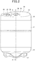
- Figure 2 is a front view of the muffler device.
- Figure 3 is a sectional view in line A-A in Figure 2 .
- Figure 4 is a sectional view in line B-B in Figure 3 .
- Figure 5 is a sectional view in line C-C in Figure 4 .
- the muffler device 20 includes a casing 21, and the casing 21 is formed into an elliptical shape in plan view and has a flat shape in a front-rear direction.
- the casing 21 is formed, for example, by doubly winding and molding a plate-shaped member. In the present embodiment, the casing 21 is installed vertically.
- a top cover 22 that forms an end cover is attached to an upper portion of the casing 21, and an undercover 23 forming an end cover is attached to a lower portion of the casing 21.
- a top surface includes an inclined surface 24 that inclines downward to a front.
- the top cover 22 has a rear part formed in a curved surface shape, and is formed into a substantially trapezoidal shape in side view.
- An exhaust hole 25 for connecting an exhaust pipe (not illustrated) is formed on one side of the inclined surface 24 of the casing 21, and a tail pipe hole 26 for connecting a tail pipe 60 is formed in a substantially center of the inclined surface 24, respectively.
- the undercover 23 has a shape in which corner portions in the front-rear direction are formed into curved surface shapes, and a central portion swells downward, and is formed into a substantially trapezoidal shape in side view as a whole.
- An attaching flange 27 is formed on an undersurface of the undercover 23 to protrude downward.
- screw holes 28 are formed respectively in a periphery of the exhaust hole 25 and in a periphery of the tail pipe hole 26.
- a first partition wall 30 and a second partition wall 31 that are disposed with a predetermined space in an up-down direction are respectively provided in an inside of the casing 21.
- the inside of the casing 21 is partitioned into an upper first chamber 32, an intermediate second chamber 33, and a lower third chamber 34 by the first partition wall 30 and the second partition wall 31.
- the first chamber 32 communicates with the exhaust hole 25.
- the second partition wall 31 is provided with a communication hole 35 that allows the second chamber 33 and the third chamber 34 to communicate with each other.
- a catalyst device 40 that extends in a vertical direction to penetrate through the first partition wall 30 and the second partition wall 31 is provided. Pores 41 by punching that open to the first chamber 32 are formed in an upper portion of the catalyst device 40. Pores 42 by punching that open to the second chamber 33 are formed in a lower portion of the catalyst device 40.
- a diffuser pipe 50 that extends over a substantially entire region in the up-down direction by penetrating through the first partition wall 30 and the second partition wall 31 is provided.
- the diffuser pipe 50 is formed of an outer tube 51 and an inner tube 52, and a large number of pores 53 formed by punching are formed in the inner tube 52.
- the outer tube 51 and the inner tube 52 are integrally formed by welding or the like on upper sides and lower sides thereof.
- connection pipe 54 that is connected to the tail pipe hole 26 is connected to an upper end portion of the outer tube 51, and an arrester 55 is disposed inside of the connection pipe 54.
- the diffuser pipe 50 is disposed between the exhaust hole 25 that is a connection portion of the exhaust pipe, and a placement position of the catalyst device 40. Accordingly, high-temperature exhaust gas that flows into the first chamber 32 from the exhaust pipe is cooled before flowing into the catalyst device 40, and it becomes possible to prevent the catalyst device 40 from being deteriorated by the high-temperature exhaust gas.
- the arrester 55 is disposed in an inside of the connection pipe 54 of the diffuser pipe 50, it becomes possible to achieve compactification while keeping a silencing function.
- the muffler device 20 of the present embodiment is attached to the generator 1, for example, by fixing the attaching flange 27 to a crankcase of the engine by screws, and fastening the exhaust pipe to the exhaust hole 25 by screws via the screw holes 28.
- Exhaust gas generated from the engine firstly flows into the first chamber 32 of the casing 21 via the exhaust hole 25 via the exhaust pipe. At this time, the exhaust gas can be caused to flow into the casing 21 in a state where a temperature of the exhaust gas is reduced by effectively using cooling air of the engine, by connecting the exhaust pipe to the inclined surface 24 of the top cover 22.
- the exhaust gas flowing into the first chamber 32 enters the catalyst device 40 via the pores 41, and after the exhaust gas passes through the catalyst device 40, the exhaust gas flows into the second chamber 33 via the pores 42.
- the diffuser pipe 50 is disposed between the connection portion of the exhaust pipe, and the placement position of the catalyst device 40, a space in which the exhaust gas flowing into the first chamber 32 exists before entering the catalyst device 40 can be secured to be wide at this time, whereby the high-temperature exhaust gas flowing into the first chamber 32 from the exhaust pipe is cooled before flowing into the catalyst device 40. As a result, it becomes possible to prevent the catalyst device 40 from being deteriorated by the high-temperature exhaust gas.
- the exhaust gas is caused to flow into the catalyst device 40 via the pores 41 of the catalyst device 40, it is possible to reduce a flow velocity of the exhaust gas, and it is possible to reduce occurrence of airflow noise.
- the exhaust gas flowing in the second chamber 33 from the catalyst device 40 flows into the third chamber 34 via communication holes 35, and flows into a lower end of the diffuser pipe 50 from the third chamber 34.
- the exhaust gas flowing into the diffuser pipe 50 flows out to inside of the outer tube 51 via the pores 53 from the inner tube 52, and flows to inside of the inner tube 52 via the pores 53 again. By repeating this, airflow noise and vibration sound can be reduced.
- the exhaust gas flowing in the diffuser pipe 50 is released to an outside from the tail pipe 60 via the arrester 55.
- the casing 21 that is disposed vertically is included, and the top cover 22 and the undercover 23 (end cover) that are provided on a top and a bottom of the casing 21 are each formed into a substantially trapezoidal shape.
- an inner capacity of the casing 21 can be secured to be large, and rigidity can be also enhanced.
- the size of the muffler device 20 can be reduced, and no extra parts are required, so that reduction in manufacturing cost and reduction in weight can be achieved.
- the casing 21 is disposed vertically, it is possible to install the casing 21 even when an installation space is small inside of the housing of the generator 1, and it is possible to reduce the size of the generator 1.
- the end cover is formed of the top cover 22 provided on the upper portion of the casing 21, and the undercover 23 provided on the lower portion of the casing 21, the inclined surface 24 is formed on the top surface of the top cover 22, and the exhaust pipe and the tail pipe 60 are connected to the inclined surface 24 of the top cover 22.
- connection portions of the exhaust pipe and the tail pipe 60 are concentrated on the upper portion of the casing 21, and it is possible to improve maintainability.
- the catalyst device 40 is included in the inside of the casing 21, and the catalyst device 40 is disposed in the vertical direction.
- the diffuser pipe 50 is disposed between the connection portion of the exhaust pipe on the top cover 22, and the placement position of the catalyst device 40, in the inside of the casing 21.
- the diffuser pipe 50 is disposed between the connection portion of the exhaust pipe, and the placement position of the catalyst device 40, the space where the exhaust gas flowing in the casing 21 exits before entering the catalyst device 40 can be secured to be wide.
- the high-temperature exhaust gas flowing into the casing 21 from the exhaust pipe is cooled before flowing into the catalyst device 40, and it becomes possible to prevent the catalyst device 40 from being deteriorated by the high-temperature exhaust gas.
- the diffuser pipe 50 extends over the substantially entire region in the up-down direction of the casing 21, and the arrester 55 is disposed in the connection portion of the diffuser pipe 50 to the tail pipe 60.
- the arrester 55 is disposed in the inside of the connection pipe 54 of the diffuser pipe 50, it is possible to reduce the size while keeping the silencing function.
Landscapes
- Engineering & Computer Science (AREA)
- Chemical & Material Sciences (AREA)
- Combustion & Propulsion (AREA)
- Mechanical Engineering (AREA)
- General Engineering & Computer Science (AREA)
- Health & Medical Sciences (AREA)
- Chemical Kinetics & Catalysis (AREA)
- Toxicology (AREA)
- Exhaust Silencers (AREA)
- Exhaust Gas After Treatment (AREA)
Abstract
Description
- The present invention relates to a muffler device, and particularly relates to a muffler device that is applied to an engine of a portable generator.
- There has been conventionally known a muffler device for silencing an engine.
- As the muffler device like this, for example, there is conventionally disclosed a technology that includes outer plates, and a cylindrical outer shell that supports the respective outer plates, and reduces exhaust noise by reducing exhaust energy in a muffler (refer to
Patent Literature 1, for example). - [Patent Literature 1]
Japanese Patent Laid-Open No.2005-155551 - The above described conventional technology is a technology concerning a muffler device of an engine for a vehicle. However, there is known a generator that drives an engine and generates power by the driving force, and the aforementioned conventional technology cannot be directly applied as the muffler device of the generator like this.
- In particular, a portable generator needs to be equipped with a catalyst device to purify NOx, and in addition, the portable generator is required to be lightweight and compact.
- An aspect of the present invention is made in the light of the aforementioned point, and has an object to provide a lightweight and compact muffler device that can be installed in a limited space in an inside of a generator, and can ensure a sufficient capacity.
- In order to attain the above described object, an aspect of the present invention is a muffler device of a portable generator, including a casing disposed vertically, wherein end covers provided on a top and a bottom of the casing are each formed in a substantially trapezoidal shape.
- According to an aspect of the present invention, an inner capacity of the casing can be secured to be larger as compared with a case where the end covers are each formed into a planar shape, and rigidity can also be enhanced. As a result, the size of the muffler device can be made compact, and no extra component is required, so that reduction in manufacturing cost and reduction in weight can be achieved. Further, since the casing is disposed vertically, it becomes possible to install the casing even when the installation space is small in the inside of the housing of the generator, and it becomes possible to make the generator compact.
- In the above described configuration, the end covers are formed of a top cover provided at an upper portion of the casing, and an undercover provided at a lower portion of the casing, and an inclined surface is formed on a top surface of the top cover, and an exhaust pipe and a tail pipe are connected to the inclined surface of the top cover.
- According to the present invention, it becomes possible to concentrate the connection portions to the exhaust pipe and the tail pipe on the upper portion of the casing, and maintainability can be improved.
- The above described configuration includes a catalyst device in an inside of the casing, wherein the catalyst device is disposed in a vertical direction.
- According to an aspect of the present invention, by disposing the catalyst device in the vertical direction, carbon in the inside of the catalyst device can be made difficult to accumulate.
- In the above described configuration, a diffuser pipe is disposed between a connection portion of the top cover to the exhaust pipe, and a placement position of the catalyst device, in the inside of the casing.
- According to an aspect of the present invention, the diffuser pipe is disposed between the connection portion to the exhaust pipe, and the placement position of the catalyst device, and therefore, a space in which the exhaust gas flowing into the casing exists before entering the catalyst device can be secured to be wide. As a result, the high-temperature exhaust gas flowing into the casing from the exhaust pipe is cooled before flowing into the catalyst device, and it becomes possible to prevent the catalyst device from being deteriorated by the high-temperature exhaust gas.
- In the above described configuration, the diffuser pipe extends over a substantially entire region in an up-down direction of the casing, and an arrester is disposed in a connection portion of the diffuser pipe to the tail pipe.
- According to an aspect of the present invention, the arrester is disposed in the inside of the connection pipe of the diffuser pipe, and therefore, reduction in size can be achieved while the silencing function is kept.
- The specification claims the benefit of priority of Japanese Patent Application No.
2017-243064 filed on December 19, 2017 - According to an aspect of the present invention, as compared with the case where the end covers are each formed in a planar shape, the inner capacity of the casing can be secured to be larger, and rigidity can also be enhanced. As a result, the size of the muffler device can be made compact, and no extra component is required, so that reduction in manufacturing cost and reduction in weight can be achieved. Further, since the casing is disposed vertically, it becomes possible to install the casing even when the installation space is small in the inside of the housing of the generator, and the generator can be made compact.
-
- [
Figure 1] Figure 1 is an external view illustrating an embodiment of a generator to which a muffler device of the present invention is applied. - [
Figure 2] Figure 2 is a front view of the muffler device of the present embodiment. - [
Figure 3] Figure 3 is a sectional view in line A-A inFigure 2 . - [
Figure 4] Figure 4 is a sectional view in line B-B inFigure 3 . - [
Figure 5] Figure 5 is a sectional view in line C-C inFigure 4 . - Hereinafter, an embodiment of the present invention will be described with reference to the drawings.
-
Figure 1 is a perspective view illustrating an external appearance of a portable generator to which a muffler device according to the present invention is applied. - As illustrated in
Figure 1 , agenerator 1 includes ahousing 10 in a substantially rectangular parallelepiped shape, and an engine (not illustrated) and a muffler device 20 (refer toFigure 2 ) are housed in a lower part inside of thehousing 10. Power generation is enabled via an alternator by driving the engine. - Further, a
control panel 13 in whichpower outlets 11,operation buttons 12 and the like are disposed is fitted to one side surface of thehousing 10. - Further, a
handle 15 is provided on a top surface of thehousing 10, and a plurality oflegs 16 that support thehousing 10 are attached to an undersurface of thehousing 10. - Next, the muffler device will be described.
-
Figure 2 is a front view of the muffler device.Figure 3 is a sectional view in line A-A inFigure 2 .Figure 4 is a sectional view in line B-B inFigure 3 .Figure 5 is a sectional view in line C-C inFigure 4 . - As illustrated in
Figure 2 to Figure 5 , themuffler device 20 includes acasing 21, and thecasing 21 is formed into an elliptical shape in plan view and has a flat shape in a front-rear direction. Thecasing 21 is formed, for example, by doubly winding and molding a plate-shaped member. In the present embodiment, thecasing 21 is installed vertically. - Further, a
top cover 22 that forms an end cover is attached to an upper portion of thecasing 21, and an undercover 23 forming an end cover is attached to a lower portion of thecasing 21. In thetop cover 22, a top surface includes aninclined surface 24 that inclines downward to a front. Further, thetop cover 22 has a rear part formed in a curved surface shape, and is formed into a substantially trapezoidal shape in side view. - An
exhaust hole 25 for connecting an exhaust pipe (not illustrated) is formed on one side of theinclined surface 24 of thecasing 21, and atail pipe hole 26 for connecting atail pipe 60 is formed in a substantially center of theinclined surface 24, respectively. - In the present embodiment, by connecting the exhaust pipe to the
inclined surface 24 of thecasing 21, it is possible to apply cooling air for the engine to the exhaust pipe, and it is possible to reduce a temperature of exhaust gas of the engine, which flows in the exhaust pipe. - The undercover 23 has a shape in which corner portions in the front-rear direction are formed into curved surface shapes, and a central portion swells downward, and is formed into a substantially trapezoidal shape in side view as a whole. An attaching
flange 27 is formed on an undersurface of the undercover 23 to protrude downward. - Further,
screw holes 28 are formed respectively in a periphery of theexhaust hole 25 and in a periphery of thetail pipe hole 26. - A
first partition wall 30 and asecond partition wall 31 that are disposed with a predetermined space in an up-down direction are respectively provided in an inside of thecasing 21. The inside of thecasing 21 is partitioned into an upperfirst chamber 32, an intermediatesecond chamber 33, and a lowerthird chamber 34 by thefirst partition wall 30 and thesecond partition wall 31. Thefirst chamber 32 communicates with theexhaust hole 25. Thesecond partition wall 31 is provided with acommunication hole 35 that allows thesecond chamber 33 and thethird chamber 34 to communicate with each other. - In the inside of the
casing 21, acatalyst device 40 that extends in a vertical direction to penetrate through thefirst partition wall 30 and thesecond partition wall 31 is provided.Pores 41 by punching that open to thefirst chamber 32 are formed in an upper portion of thecatalyst device 40.Pores 42 by punching that open to thesecond chamber 33 are formed in a lower portion of thecatalyst device 40. - By disposing the
catalyst device 40 in the vertical direction in this way, it is possible to make it difficult for carbon inside of thecatalyst device 40 to accumulate. - In the inside of the
casing 21, adiffuser pipe 50 that extends over a substantially entire region in the up-down direction by penetrating through thefirst partition wall 30 and thesecond partition wall 31 is provided. Thediffuser pipe 50 is formed of anouter tube 51 and aninner tube 52, and a large number ofpores 53 formed by punching are formed in theinner tube 52. Theouter tube 51 and theinner tube 52 are integrally formed by welding or the like on upper sides and lower sides thereof. - A
connection pipe 54 that is connected to thetail pipe hole 26 is connected to an upper end portion of theouter tube 51, and anarrester 55 is disposed inside of theconnection pipe 54. - In the present embodiment, the
diffuser pipe 50 is disposed between theexhaust hole 25 that is a connection portion of the exhaust pipe, and a placement position of thecatalyst device 40. Accordingly, high-temperature exhaust gas that flows into thefirst chamber 32 from the exhaust pipe is cooled before flowing into thecatalyst device 40, and it becomes possible to prevent thecatalyst device 40 from being deteriorated by the high-temperature exhaust gas. - Further, since the
arrester 55 is disposed in an inside of theconnection pipe 54 of thediffuser pipe 50, it becomes possible to achieve compactification while keeping a silencing function. - The
muffler device 20 of the present embodiment is attached to thegenerator 1, for example, by fixing the attachingflange 27 to a crankcase of the engine by screws, and fastening the exhaust pipe to theexhaust hole 25 by screws via the screw holes 28. - It is possible to detach the
muffler device 20 easily by only detaching the respective screws. As a result, maintenance of themuffler device 20 can be performed easily. - Next, an operation of the
muffler device 20 configured in this way will be described. - Exhaust gas generated from the engine firstly flows into the
first chamber 32 of thecasing 21 via theexhaust hole 25 via the exhaust pipe. At this time, the exhaust gas can be caused to flow into thecasing 21 in a state where a temperature of the exhaust gas is reduced by effectively using cooling air of the engine, by connecting the exhaust pipe to theinclined surface 24 of thetop cover 22. - The exhaust gas flowing into the
first chamber 32 enters thecatalyst device 40 via thepores 41, and after the exhaust gas passes through thecatalyst device 40, the exhaust gas flows into thesecond chamber 33 via thepores 42. - Since the
diffuser pipe 50 is disposed between the connection portion of the exhaust pipe, and the placement position of thecatalyst device 40, a space in which the exhaust gas flowing into thefirst chamber 32 exists before entering thecatalyst device 40 can be secured to be wide at this time, whereby the high-temperature exhaust gas flowing into thefirst chamber 32 from the exhaust pipe is cooled before flowing into thecatalyst device 40. As a result, it becomes possible to prevent thecatalyst device 40 from being deteriorated by the high-temperature exhaust gas. - Further, since the exhaust gas is caused to flow into the
catalyst device 40 via thepores 41 of thecatalyst device 40, it is possible to reduce a flow velocity of the exhaust gas, and it is possible to reduce occurrence of airflow noise. - The exhaust gas flowing in the
second chamber 33 from thecatalyst device 40 flows into thethird chamber 34 via communication holes 35, and flows into a lower end of thediffuser pipe 50 from thethird chamber 34. The exhaust gas flowing into thediffuser pipe 50 flows out to inside of theouter tube 51 via thepores 53 from theinner tube 52, and flows to inside of theinner tube 52 via thepores 53 again. By repeating this, airflow noise and vibration sound can be reduced. - The exhaust gas flowing in the
diffuser pipe 50 is released to an outside from thetail pipe 60 via thearrester 55. - As described above, in the present embodiment, the
casing 21 that is disposed vertically is included, and thetop cover 22 and the undercover 23 (end cover) that are provided on a top and a bottom of thecasing 21 are each formed into a substantially trapezoidal shape. - Thereby, as compared with a case where the
top cover 22 and the undercover 23 are each formed into a planar shape, an inner capacity of thecasing 21 can be secured to be large, and rigidity can be also enhanced. As a result, the size of themuffler device 20 can be reduced, and no extra parts are required, so that reduction in manufacturing cost and reduction in weight can be achieved. Further, since thecasing 21 is disposed vertically, it is possible to install thecasing 21 even when an installation space is small inside of the housing of thegenerator 1, and it is possible to reduce the size of thegenerator 1. - Further, in the present embodiment, the end cover is formed of the
top cover 22 provided on the upper portion of thecasing 21, and the undercover 23 provided on the lower portion of thecasing 21, theinclined surface 24 is formed on the top surface of thetop cover 22, and the exhaust pipe and thetail pipe 60 are connected to theinclined surface 24 of thetop cover 22. - Thereby, it is possible to concentrate the connection portions of the exhaust pipe and the
tail pipe 60 on the upper portion of thecasing 21, and it is possible to improve maintainability. - Further, in the present embodiment, the
catalyst device 40 is included in the inside of thecasing 21, and thecatalyst device 40 is disposed in the vertical direction. - Accordingly, it is possible to make it difficult for carbon inside of the
catalyst device 40 to accumulate, by disposing thecatalyst device 40 in the vertical direction. - Further, in the present embodiment, the
diffuser pipe 50 is disposed between the connection portion of the exhaust pipe on thetop cover 22, and the placement position of thecatalyst device 40, in the inside of thecasing 21. - Accordingly, since the
diffuser pipe 50 is disposed between the connection portion of the exhaust pipe, and the placement position of thecatalyst device 40, the space where the exhaust gas flowing in thecasing 21 exits before entering thecatalyst device 40 can be secured to be wide. As a result, the high-temperature exhaust gas flowing into thecasing 21 from the exhaust pipe is cooled before flowing into thecatalyst device 40, and it becomes possible to prevent thecatalyst device 40 from being deteriorated by the high-temperature exhaust gas. - Further, in the present embodiment, the
diffuser pipe 50 extends over the substantially entire region in the up-down direction of thecasing 21, and thearrester 55 is disposed in the connection portion of thediffuser pipe 50 to thetail pipe 60. - Accordingly, since the
arrester 55 is disposed in the inside of theconnection pipe 54 of thediffuser pipe 50, it is possible to reduce the size while keeping the silencing function. - Note that the present invention is not limited to what is described in the above described embodiment, but various modifications and changes can be made within the range without departing from the gist of the present invention.
-
- 1
- Generator
- 10
- Housing
- 20
- Muffler device
- 21
- Casing
- 22
- Top cover
- 23
- Undercover
- 24
- Inclined surface
- 25
- Exhaust hole
- 26
- Tail pipe hole
- 30
- First partition wall
- 31
- Second partition wall
- 32
- First chamber
- 33
- Second chamber
- 34
- Third chamber
- 35
- Communication hole
- 40
- Catalyst device
- 50
- Diffuser pipe
- 51
- Outer tube
- 52
- Inner tube
- 54
- Communication pipe
- 55
- Arrester
- 60
- Tail pipe
Claims (5)
- A muffler device of a portable generator, comprising:
a casing disposed vertically, wherein end covers provided on a top and a bottom of the casing are each formed in a substantially trapezoidal shape. - The muffler device according to claim 1, wherein
the end covers are formed of a top cover provided at an upper portion of the casing, and an undercover provided at a lower portion of the casing, and
an inclined surface is formed on a top surface of the top cover, and an exhaust pipe and a tail pipe are connected to the inclined surface of the top cover. - The muffler device according to claim 2, comprising a catalyst device in an inside of the casing, and the catalyst device is disposed in a vertical direction.
- The muffler device according to claim 3, wherein
a diffuser pipe is disposed between a connection portion of the top cover to the exhaust pipe and a placement position of the catalyst device, in the inside of the casing. - The muffler device according to claim 4, wherein
the diffuser pipe extends over a substantially entire region in an up-down direction of the casing, and an arrester is disposed in a connection portion of the diffuser pipe to the tail pipe.
Applications Claiming Priority (2)
| Application Number | Priority Date | Filing Date | Title |
|---|---|---|---|
| JP2017243064 | 2017-12-19 | ||
| PCT/JP2018/029214 WO2019123708A1 (en) | 2017-12-19 | 2018-08-03 | Muffler device |
Publications (3)
| Publication Number | Publication Date |
|---|---|
| EP3677757A1 true EP3677757A1 (en) | 2020-07-08 |
| EP3677757A4 EP3677757A4 (en) | 2021-03-10 |
| EP3677757B1 EP3677757B1 (en) | 2021-09-22 |
Family
ID=66993220
Family Applications (1)
| Application Number | Title | Priority Date | Filing Date |
|---|---|---|---|
| EP18891784.3A Active EP3677757B1 (en) | 2017-12-19 | 2018-08-03 | Muffler device |
Country Status (5)
| Country | Link |
|---|---|
| US (1) | US11377991B2 (en) |
| EP (1) | EP3677757B1 (en) |
| JP (1) | JP6752984B2 (en) |
| CN (1) | CN111492125B (en) |
| WO (1) | WO2019123708A1 (en) |
Families Citing this family (8)
| Publication number | Priority date | Publication date | Assignee | Title |
|---|---|---|---|---|
| JP2020133477A (en) * | 2019-02-19 | 2020-08-31 | 本田技研工業株式会社 | Exhaust muffler structure |
| USD1085007S1 (en) | 2023-10-11 | 2025-07-22 | Northern Tool & Equipment Company, Inc. | Generator assembly |
| USD1085010S1 (en) | 2023-10-11 | 2025-07-22 | Northern Tool & Equipment Company, Inc. | Generator assembly |
| USD1085006S1 (en) | 2023-10-11 | 2025-07-22 | Northern Tool & Equipment Company, Inc. | Generator assembly |
| USD1085008S1 (en) | 2023-10-11 | 2025-07-22 | Northern Tool & Equipment Company, Inc. | Generator assembly |
| USD1085011S1 (en) | 2023-10-11 | 2025-07-22 | Northern Tool & Equipment Company, Inc. | Generator assembly |
| USD1085009S1 (en) | 2023-10-11 | 2025-07-22 | Northern Tool & Equipment Company, Inc. | Generator assembly |
| USD1085012S1 (en) | 2023-10-11 | 2025-07-22 | Northern Tool & Equipment Company, Inc. | Generator assembly |
Family Cites Families (19)
| Publication number | Priority date | Publication date | Assignee | Title |
|---|---|---|---|---|
| DE3729477C3 (en) * | 1987-09-03 | 1999-09-09 | Stihl Maschf Andreas | Exhaust silencer for two-stroke engines, especially for portable tools such as chainsaws |
| DE9314441U1 (en) * | 1992-02-19 | 1994-01-13 | Leistritz AG & Co Abgastechnik, 90765 Fürth | Exhaust silencer for diesel engines, especially of commercial vehicles |
| DE19626980A1 (en) * | 1996-07-04 | 1998-02-26 | Roth Technik Austria | Silencers for automobiles |
| JP2005155551A (en) | 2003-11-27 | 2005-06-16 | Toyota Motor Corp | Muffler |
| DE10357941B4 (en) * | 2003-12-09 | 2006-03-23 | J. Eberspächer GmbH & Co. KG | Silencer for an exhaust system |
| JP4444730B2 (en) * | 2004-05-17 | 2010-03-31 | 川崎重工業株式会社 | Small engine muffler |
| US7287622B2 (en) * | 2004-12-20 | 2007-10-30 | Arctic Cat Inc. | Exhaust muffler |
| JP2006207531A (en) | 2005-01-31 | 2006-08-10 | Ishikawajima Harima Heavy Ind Co Ltd | Silencer integrated denitration apparatus, internal combustion engine equipped with the denitration apparatus, and power generation system equipped with the internal combustion engine |
| JP4655743B2 (en) * | 2005-04-27 | 2011-03-23 | スズキ株式会社 | Motorcycle exhaust system |
| JP5965340B2 (en) | 2013-03-21 | 2016-08-03 | ヤンマー株式会社 | Engine exhaust gas system equipment and packaged engine generator |
| JP6137683B2 (en) | 2013-08-08 | 2017-05-31 | 株式会社ユタカ技研 | Engine exhaust muffler |
| US8997922B1 (en) * | 2013-10-24 | 2015-04-07 | Kawasaki Jukogyo Kabushiki Kaisha | Exhaust muffler for vehicle |
| CN204175376U (en) | 2014-09-22 | 2015-02-25 | 诸城市海得威机械有限公司 | A kind of low back pressure impedance complex exhaust silencer |
| CN204175367U (en) * | 2014-09-22 | 2015-02-25 | 诸城市海得威机械有限公司 | A kind of special exhaust silencer except high-frequency noise |
| CN104265404A (en) * | 2014-09-27 | 2015-01-07 | 诸城市海得威机械有限公司 | Round exhaust silencer for vehicles |
| CN204175364U (en) * | 2014-09-27 | 2015-02-25 | 诸城市海得威机械有限公司 | A kind of circular automobile exhaust gas Sound Attenuator |
| JP6426500B2 (en) * | 2015-03-05 | 2018-11-21 | 本田技研工業株式会社 | Exhaust system with oxygen sensor |
| JP5986252B1 (en) | 2015-03-26 | 2016-09-06 | 本田技研工業株式会社 | Engine driven generator |
| US20170087514A1 (en) | 2015-09-30 | 2017-03-30 | Caterpillar Inc. | Uniform flow distribution of a reductant |
-
2018
- 2018-08-03 EP EP18891784.3A patent/EP3677757B1/en active Active
- 2018-08-03 US US16/757,587 patent/US11377991B2/en active Active
- 2018-08-03 JP JP2019560029A patent/JP6752984B2/en not_active Expired - Fee Related
- 2018-08-03 CN CN201880080753.4A patent/CN111492125B/en not_active Expired - Fee Related
- 2018-08-03 WO PCT/JP2018/029214 patent/WO2019123708A1/en not_active Ceased
Also Published As
| Publication number | Publication date |
|---|---|
| JPWO2019123708A1 (en) | 2020-08-06 |
| CN111492125A (en) | 2020-08-04 |
| US20210199034A1 (en) | 2021-07-01 |
| EP3677757B1 (en) | 2021-09-22 |
| EP3677757A4 (en) | 2021-03-10 |
| JP6752984B2 (en) | 2020-09-09 |
| WO2019123708A1 (en) | 2019-06-27 |
| US11377991B2 (en) | 2022-07-05 |
| CN111492125B (en) | 2021-11-26 |
Similar Documents
| Publication | Publication Date | Title |
|---|---|---|
| US11377991B2 (en) | Muffler device | |
| EP2917059B1 (en) | Air guide structure for an engine compartment of a vehicle | |
| US7686131B1 (en) | Vehicle exhaust tip assembly | |
| EP2463503A1 (en) | A cylinder head mount | |
| JP2016141354A (en) | Battery unit and battery frame | |
| JP2017071943A (en) | Construction machinery | |
| CA3171500A1 (en) | Catalytic converter guard | |
| CN109941095A (en) | Exhaust system for internal combustion engine of motor vehicle and motor vehicle | |
| EP2961956B1 (en) | Exhaust manifold with turbo support | |
| CN104969451A (en) | Structure for mounting diesel oxidation catalyst device to generator motor | |
| WO2015060080A1 (en) | Structure for affixing inflator and airbag | |
| CN104246082B (en) | Mounting structure for mounting a diesel oxidation catalyst device on a generator motor | |
| JP6806663B2 (en) | Muffler device | |
| JP2010154603A (en) | Structure of air supply duct for cooling power unit | |
| CN110273732B (en) | Exhaust with spark arrester | |
| JP6806664B2 (en) | Muffler device | |
| CN209843795U (en) | Battery pack case and its power battery pack | |
| JP2006090243A (en) | Motor fan shroud | |
| JP2012223032A (en) | Electric power conversion device | |
| JP4829059B2 (en) | Engine power generator | |
| KR100641392B1 (en) | Heavy Equipment Exhaust System | |
| US20230178786A1 (en) | Fuel cell system structure | |
| KR101309020B1 (en) | Car muffler | |
| JP5364495B2 (en) | Exhaust silencer support structure | |
| CN217152081U (en) | Electronic component mounting device and exhaust gas post-treatment device provided with same |
Legal Events
| Date | Code | Title | Description |
|---|---|---|---|
| STAA | Information on the status of an ep patent application or granted ep patent |
Free format text: STATUS: THE INTERNATIONAL PUBLICATION HAS BEEN MADE |
|
| PUAI | Public reference made under article 153(3) epc to a published international application that has entered the european phase |
Free format text: ORIGINAL CODE: 0009012 |
|
| STAA | Information on the status of an ep patent application or granted ep patent |
Free format text: STATUS: REQUEST FOR EXAMINATION WAS MADE |
|
| 17P | Request for examination filed |
Effective date: 20200331 |
|
| AK | Designated contracting states |
Kind code of ref document: A1 Designated state(s): AL AT BE BG CH CY CZ DE DK EE ES FI FR GB GR HR HU IE IS IT LI LT LU LV MC MK MT NL NO PL PT RO RS SE SI SK SM TR |
|
| AX | Request for extension of the european patent |
Extension state: BA ME |
|
| A4 | Supplementary search report drawn up and despatched |
Effective date: 20210208 |
|
| RIC1 | Information provided on ipc code assigned before grant |
Ipc: F01N 3/10 20060101ALI20210202BHEP Ipc: F01N 1/02 20060101ALI20210202BHEP Ipc: F01N 1/00 20060101AFI20210202BHEP Ipc: F01N 1/08 20060101ALI20210202BHEP |
|
| DAV | Request for validation of the european patent (deleted) | ||
| DAX | Request for extension of the european patent (deleted) | ||
| GRAP | Despatch of communication of intention to grant a patent |
Free format text: ORIGINAL CODE: EPIDOSNIGR1 |
|
| STAA | Information on the status of an ep patent application or granted ep patent |
Free format text: STATUS: GRANT OF PATENT IS INTENDED |
|
| INTG | Intention to grant announced |
Effective date: 20210526 |
|
| GRAS | Grant fee paid |
Free format text: ORIGINAL CODE: EPIDOSNIGR3 |
|
| GRAA | (expected) grant |
Free format text: ORIGINAL CODE: 0009210 |
|
| STAA | Information on the status of an ep patent application or granted ep patent |
Free format text: STATUS: THE PATENT HAS BEEN GRANTED |
|
| AK | Designated contracting states |
Kind code of ref document: B1 Designated state(s): AL AT BE BG CH CY CZ DE DK EE ES FI FR GB GR HR HU IE IS IT LI LT LU LV MC MK MT NL NO PL PT RO RS SE SI SK SM TR |
|
| REG | Reference to a national code |
Ref country code: GB Ref legal event code: FG4D |
|
| REG | Reference to a national code |
Ref country code: DE Ref legal event code: R096 Ref document number: 602018024102 Country of ref document: DE |
|
| REG | Reference to a national code |
Ref country code: IE Ref legal event code: FG4D |
|
| REG | Reference to a national code |
Ref country code: CH Ref legal event code: EP Ref country code: AT Ref legal event code: REF Ref document number: 1432486 Country of ref document: AT Kind code of ref document: T Effective date: 20211015 |
|
| REG | Reference to a national code |
Ref country code: LT Ref legal event code: MG9D |
|
| REG | Reference to a national code |
Ref country code: NL Ref legal event code: MP Effective date: 20210922 |
|
| PG25 | Lapsed in a contracting state [announced via postgrant information from national office to epo] |
Ref country code: SE Free format text: LAPSE BECAUSE OF FAILURE TO SUBMIT A TRANSLATION OF THE DESCRIPTION OR TO PAY THE FEE WITHIN THE PRESCRIBED TIME-LIMIT Effective date: 20210922 Ref country code: RS Free format text: LAPSE BECAUSE OF FAILURE TO SUBMIT A TRANSLATION OF THE DESCRIPTION OR TO PAY THE FEE WITHIN THE PRESCRIBED TIME-LIMIT Effective date: 20210922 Ref country code: FI Free format text: LAPSE BECAUSE OF FAILURE TO SUBMIT A TRANSLATION OF THE DESCRIPTION OR TO PAY THE FEE WITHIN THE PRESCRIBED TIME-LIMIT Effective date: 20210922 Ref country code: BG Free format text: LAPSE BECAUSE OF FAILURE TO SUBMIT A TRANSLATION OF THE DESCRIPTION OR TO PAY THE FEE WITHIN THE PRESCRIBED TIME-LIMIT Effective date: 20211222 Ref country code: LT Free format text: LAPSE BECAUSE OF FAILURE TO SUBMIT A TRANSLATION OF THE DESCRIPTION OR TO PAY THE FEE WITHIN THE PRESCRIBED TIME-LIMIT Effective date: 20210922 Ref country code: NO Free format text: LAPSE BECAUSE OF FAILURE TO SUBMIT A TRANSLATION OF THE DESCRIPTION OR TO PAY THE FEE WITHIN THE PRESCRIBED TIME-LIMIT Effective date: 20211222 Ref country code: HR Free format text: LAPSE BECAUSE OF FAILURE TO SUBMIT A TRANSLATION OF THE DESCRIPTION OR TO PAY THE FEE WITHIN THE PRESCRIBED TIME-LIMIT Effective date: 20210922 |
|
| REG | Reference to a national code |
Ref country code: AT Ref legal event code: MK05 Ref document number: 1432486 Country of ref document: AT Kind code of ref document: T Effective date: 20210922 |
|
| PG25 | Lapsed in a contracting state [announced via postgrant information from national office to epo] |
Ref country code: LV Free format text: LAPSE BECAUSE OF FAILURE TO SUBMIT A TRANSLATION OF THE DESCRIPTION OR TO PAY THE FEE WITHIN THE PRESCRIBED TIME-LIMIT Effective date: 20210922 Ref country code: GR Free format text: LAPSE BECAUSE OF FAILURE TO SUBMIT A TRANSLATION OF THE DESCRIPTION OR TO PAY THE FEE WITHIN THE PRESCRIBED TIME-LIMIT Effective date: 20211223 |
|
| PG25 | Lapsed in a contracting state [announced via postgrant information from national office to epo] |
Ref country code: AT Free format text: LAPSE BECAUSE OF FAILURE TO SUBMIT A TRANSLATION OF THE DESCRIPTION OR TO PAY THE FEE WITHIN THE PRESCRIBED TIME-LIMIT Effective date: 20210922 |
|
| PG25 | Lapsed in a contracting state [announced via postgrant information from national office to epo] |
Ref country code: IS Free format text: LAPSE BECAUSE OF FAILURE TO SUBMIT A TRANSLATION OF THE DESCRIPTION OR TO PAY THE FEE WITHIN THE PRESCRIBED TIME-LIMIT Effective date: 20220122 Ref country code: SK Free format text: LAPSE BECAUSE OF FAILURE TO SUBMIT A TRANSLATION OF THE DESCRIPTION OR TO PAY THE FEE WITHIN THE PRESCRIBED TIME-LIMIT Effective date: 20210922 Ref country code: RO Free format text: LAPSE BECAUSE OF FAILURE TO SUBMIT A TRANSLATION OF THE DESCRIPTION OR TO PAY THE FEE WITHIN THE PRESCRIBED TIME-LIMIT Effective date: 20210922 Ref country code: PT Free format text: LAPSE BECAUSE OF FAILURE TO SUBMIT A TRANSLATION OF THE DESCRIPTION OR TO PAY THE FEE WITHIN THE PRESCRIBED TIME-LIMIT Effective date: 20220124 Ref country code: PL Free format text: LAPSE BECAUSE OF FAILURE TO SUBMIT A TRANSLATION OF THE DESCRIPTION OR TO PAY THE FEE WITHIN THE PRESCRIBED TIME-LIMIT Effective date: 20210922 Ref country code: NL Free format text: LAPSE BECAUSE OF FAILURE TO SUBMIT A TRANSLATION OF THE DESCRIPTION OR TO PAY THE FEE WITHIN THE PRESCRIBED TIME-LIMIT Effective date: 20210922 Ref country code: ES Free format text: LAPSE BECAUSE OF FAILURE TO SUBMIT A TRANSLATION OF THE DESCRIPTION OR TO PAY THE FEE WITHIN THE PRESCRIBED TIME-LIMIT Effective date: 20210922 Ref country code: EE Free format text: LAPSE BECAUSE OF FAILURE TO SUBMIT A TRANSLATION OF THE DESCRIPTION OR TO PAY THE FEE WITHIN THE PRESCRIBED TIME-LIMIT Effective date: 20210922 Ref country code: CZ Free format text: LAPSE BECAUSE OF FAILURE TO SUBMIT A TRANSLATION OF THE DESCRIPTION OR TO PAY THE FEE WITHIN THE PRESCRIBED TIME-LIMIT Effective date: 20210922 Ref country code: AL Free format text: LAPSE BECAUSE OF FAILURE TO SUBMIT A TRANSLATION OF THE DESCRIPTION OR TO PAY THE FEE WITHIN THE PRESCRIBED TIME-LIMIT Effective date: 20210922 |
|
| REG | Reference to a national code |
Ref country code: DE Ref legal event code: R097 Ref document number: 602018024102 Country of ref document: DE |
|
| PG25 | Lapsed in a contracting state [announced via postgrant information from national office to epo] |
Ref country code: DK Free format text: LAPSE BECAUSE OF FAILURE TO SUBMIT A TRANSLATION OF THE DESCRIPTION OR TO PAY THE FEE WITHIN THE PRESCRIBED TIME-LIMIT Effective date: 20210922 |
|
| PLBE | No opposition filed within time limit |
Free format text: ORIGINAL CODE: 0009261 |
|
| REG | Reference to a national code |
Ref country code: DE Ref legal event code: R084 Ref document number: 602018024102 Country of ref document: DE |
|
| STAA | Information on the status of an ep patent application or granted ep patent |
Free format text: STATUS: NO OPPOSITION FILED WITHIN TIME LIMIT |
|
| 26N | No opposition filed |
Effective date: 20220623 |
|
| PG25 | Lapsed in a contracting state [announced via postgrant information from national office to epo] |
Ref country code: SI Free format text: LAPSE BECAUSE OF FAILURE TO SUBMIT A TRANSLATION OF THE DESCRIPTION OR TO PAY THE FEE WITHIN THE PRESCRIBED TIME-LIMIT Effective date: 20210922 |
|
| PG25 | Lapsed in a contracting state [announced via postgrant information from national office to epo] |
Ref country code: IT Free format text: LAPSE BECAUSE OF FAILURE TO SUBMIT A TRANSLATION OF THE DESCRIPTION OR TO PAY THE FEE WITHIN THE PRESCRIBED TIME-LIMIT Effective date: 20210922 |
|
| PG25 | Lapsed in a contracting state [announced via postgrant information from national office to epo] |
Ref country code: MC Free format text: LAPSE BECAUSE OF FAILURE TO SUBMIT A TRANSLATION OF THE DESCRIPTION OR TO PAY THE FEE WITHIN THE PRESCRIBED TIME-LIMIT Effective date: 20210922 |
|
| REG | Reference to a national code |
Ref country code: CH Ref legal event code: PL |
|
| GBPC | Gb: european patent ceased through non-payment of renewal fee |
Effective date: 20220803 |
|
| PG25 | Lapsed in a contracting state [announced via postgrant information from national office to epo] |
Ref country code: LU Free format text: LAPSE BECAUSE OF NON-PAYMENT OF DUE FEES Effective date: 20220803 Ref country code: LI Free format text: LAPSE BECAUSE OF NON-PAYMENT OF DUE FEES Effective date: 20220831 Ref country code: CH Free format text: LAPSE BECAUSE OF NON-PAYMENT OF DUE FEES Effective date: 20220831 |
|
| REG | Reference to a national code |
Ref country code: BE Ref legal event code: MM Effective date: 20220831 |
|
| PG25 | Lapsed in a contracting state [announced via postgrant information from national office to epo] |
Ref country code: IE Free format text: LAPSE BECAUSE OF NON-PAYMENT OF DUE FEES Effective date: 20220803 |
|
| PGFP | Annual fee paid to national office [announced via postgrant information from national office to epo] |
Ref country code: FR Payment date: 20230608 Year of fee payment: 6 |
|
| PG25 | Lapsed in a contracting state [announced via postgrant information from national office to epo] |
Ref country code: BE Free format text: LAPSE BECAUSE OF NON-PAYMENT OF DUE FEES Effective date: 20220831 |
|
| PG25 | Lapsed in a contracting state [announced via postgrant information from national office to epo] |
Ref country code: GB Free format text: LAPSE BECAUSE OF NON-PAYMENT OF DUE FEES Effective date: 20220803 |
|
| PG25 | Lapsed in a contracting state [announced via postgrant information from national office to epo] |
Ref country code: SM Free format text: LAPSE BECAUSE OF FAILURE TO SUBMIT A TRANSLATION OF THE DESCRIPTION OR TO PAY THE FEE WITHIN THE PRESCRIBED TIME-LIMIT Effective date: 20210922 Ref country code: MK Free format text: LAPSE BECAUSE OF FAILURE TO SUBMIT A TRANSLATION OF THE DESCRIPTION OR TO PAY THE FEE WITHIN THE PRESCRIBED TIME-LIMIT Effective date: 20210922 Ref country code: CY Free format text: LAPSE BECAUSE OF FAILURE TO SUBMIT A TRANSLATION OF THE DESCRIPTION OR TO PAY THE FEE WITHIN THE PRESCRIBED TIME-LIMIT Effective date: 20210922 |
|
| PG25 | Lapsed in a contracting state [announced via postgrant information from national office to epo] |
Ref country code: HU Free format text: LAPSE BECAUSE OF FAILURE TO SUBMIT A TRANSLATION OF THE DESCRIPTION OR TO PAY THE FEE WITHIN THE PRESCRIBED TIME-LIMIT; INVALID AB INITIO Effective date: 20180803 |
|
| PG25 | Lapsed in a contracting state [announced via postgrant information from national office to epo] |
Ref country code: TR Free format text: LAPSE BECAUSE OF FAILURE TO SUBMIT A TRANSLATION OF THE DESCRIPTION OR TO PAY THE FEE WITHIN THE PRESCRIBED TIME-LIMIT Effective date: 20210922 |
|
| PG25 | Lapsed in a contracting state [announced via postgrant information from national office to epo] |
Ref country code: MT Free format text: LAPSE BECAUSE OF FAILURE TO SUBMIT A TRANSLATION OF THE DESCRIPTION OR TO PAY THE FEE WITHIN THE PRESCRIBED TIME-LIMIT Effective date: 20210922 |
|
| PG25 | Lapsed in a contracting state [announced via postgrant information from national office to epo] |
Ref country code: FR Free format text: LAPSE BECAUSE OF NON-PAYMENT OF DUE FEES Effective date: 20240831 |
|
| PGFP | Annual fee paid to national office [announced via postgrant information from national office to epo] |
Ref country code: DE Payment date: 20250724 Year of fee payment: 8 |