JP4444730B2 - Small engine muffler - Google Patents
Small engine muffler Download PDFInfo
- Publication number
- JP4444730B2 JP4444730B2 JP2004146491A JP2004146491A JP4444730B2 JP 4444730 B2 JP4444730 B2 JP 4444730B2 JP 2004146491 A JP2004146491 A JP 2004146491A JP 2004146491 A JP2004146491 A JP 2004146491A JP 4444730 B2 JP4444730 B2 JP 4444730B2
- Authority
- JP
- Japan
- Prior art keywords
- exhaust
- exhaust gas
- muffler
- chamber
- lead
- Prior art date
- Legal status (The legal status is an assumption and is not a legal conclusion. Google has not performed a legal analysis and makes no representation as to the accuracy of the status listed.)
- Active
Links
Images


Classifications
-
- F—MECHANICAL ENGINEERING; LIGHTING; HEATING; WEAPONS; BLASTING
- F01—MACHINES OR ENGINES IN GENERAL; ENGINE PLANTS IN GENERAL; STEAM ENGINES
- F01N—GAS-FLOW SILENCERS OR EXHAUST APPARATUS FOR MACHINES OR ENGINES IN GENERAL; GAS-FLOW SILENCERS OR EXHAUST APPARATUS FOR INTERNAL COMBUSTION ENGINES
- F01N13/00—Exhaust or silencing apparatus characterised by constructional features ; Exhaust or silencing apparatus, or parts thereof, having pertinent characteristics not provided for in, or of interest apart from, groups F01N1/00 - F01N5/00, F01N9/00, F01N11/00
- F01N13/002—Apparatus adapted for particular uses, e.g. for portable devices driven by machines or engines
-
- F—MECHANICAL ENGINEERING; LIGHTING; HEATING; WEAPONS; BLASTING
- F01—MACHINES OR ENGINES IN GENERAL; ENGINE PLANTS IN GENERAL; STEAM ENGINES
- F01N—GAS-FLOW SILENCERS OR EXHAUST APPARATUS FOR MACHINES OR ENGINES IN GENERAL; GAS-FLOW SILENCERS OR EXHAUST APPARATUS FOR INTERNAL COMBUSTION ENGINES
- F01N1/00—Silencing apparatus characterised by method of silencing
- F01N1/08—Silencing apparatus characterised by method of silencing by reducing exhaust energy by throttling or whirling
- F01N1/084—Silencing apparatus characterised by method of silencing by reducing exhaust energy by throttling or whirling the gases flowing through the silencer two or more times longitudinally in opposite directions, e.g. using parallel or concentric tubes
-
- F—MECHANICAL ENGINEERING; LIGHTING; HEATING; WEAPONS; BLASTING
- F01—MACHINES OR ENGINES IN GENERAL; ENGINE PLANTS IN GENERAL; STEAM ENGINES
- F01N—GAS-FLOW SILENCERS OR EXHAUST APPARATUS FOR MACHINES OR ENGINES IN GENERAL; GAS-FLOW SILENCERS OR EXHAUST APPARATUS FOR INTERNAL COMBUSTION ENGINES
- F01N2230/00—Combination of silencers and other devices
- F01N2230/04—Catalytic converters
-
- F—MECHANICAL ENGINEERING; LIGHTING; HEATING; WEAPONS; BLASTING
- F01—MACHINES OR ENGINES IN GENERAL; ENGINE PLANTS IN GENERAL; STEAM ENGINES
- F01N—GAS-FLOW SILENCERS OR EXHAUST APPARATUS FOR MACHINES OR ENGINES IN GENERAL; GAS-FLOW SILENCERS OR EXHAUST APPARATUS FOR INTERNAL COMBUSTION ENGINES
- F01N2230/00—Combination of silencers and other devices
- F01N2230/06—Spark arresters
-
- F—MECHANICAL ENGINEERING; LIGHTING; HEATING; WEAPONS; BLASTING
- F01—MACHINES OR ENGINES IN GENERAL; ENGINE PLANTS IN GENERAL; STEAM ENGINES
- F01N—GAS-FLOW SILENCERS OR EXHAUST APPARATUS FOR MACHINES OR ENGINES IN GENERAL; GAS-FLOW SILENCERS OR EXHAUST APPARATUS FOR INTERNAL COMBUSTION ENGINES
- F01N2590/00—Exhaust or silencing apparatus adapted to particular use, e.g. for military applications, airplanes, submarines
- F01N2590/06—Exhaust or silencing apparatus adapted to particular use, e.g. for military applications, airplanes, submarines for hand-held tools or portables devices
Description
本発明は、例えば刈払機や清掃用ブロワのような携帯型作業機の動力源として用いられる小型エンジンのマフラに関するものである。 The present invention relates to a muffler for a small engine used as a power source of a portable working machine such as a brush cutter or a cleaning blower.
この種のエンジンでは、排気ガスを低温にして外部に排出することが望まれている。また、近年では、小型エンジンにおいても、排気ガス中に含まれるHCやCOを低減させることを目的として、マフラ内に酸化触媒を組み込み、この触媒で排気ガス中の未燃焼ガスを再燃焼させることが行われている。このように、マフラ内の触媒により未燃焼ガスを再燃焼させる場合は、排気口から排出される排気ガスの温度がより高温となる。このため、従来では、マフラの排気ガスの排出側に、別体で形成された副室ケースを取り付けて、この副室ケースを通過するときに排気ガスを冷却して外部に排出することが提案されている (特許文献1)。
しかし、触媒を組み込んだマフラは、排気ガスの温度が高温となるので、特許文献1のように副室ケースを設けただけでは、十分な冷却効果が得られにくい。また、エンジンが低速回転になるにつれて排気脈動の波長が長くなり、排気ガスの流速も遅くなるのに対し、特許文献1では触媒出口から排気口までの距離が短いので、脈動により排気口から吸い込まれる空気が触媒通過後の高温室に進入し易くなり、触媒で再燃焼されずに残った高温の未燃焼ガスと接触することがある。さらに、特許文献1のように、別体で形成された副室ケースをマフラの排気ガスの排出側に締結具により取り付ける場合は、部品点数および取り付け工数が増大してコストアップとなる。
However, since a muffler incorporating a catalyst has a high exhaust gas temperature, it is difficult to obtain a sufficient cooling effect only by providing a sub chamber case as in
そこで、本発明は、簡単な構造で、外部の空気との接触を防ぎながら、排気ガスの温度を十分に冷却できる小型エンジンのマフラを提供することを目的とする。 Accordingly, an object of the present invention is to provide a muffler for a small engine that has a simple structure and can sufficiently cool the temperature of exhaust gas while preventing contact with outside air.
上記目的を達成するために、本発明の小型エンジンのマフラは、エンジンの排気ガスを消音するマフラであって、排気室を形成するボディの内部に、排気ガスの排気口に連通する導出通路が設けられ、前記導出通路の側壁は、前記ボディの一部と、ボディに接合されたダクト壁とにより形成され、前記ダクト壁が横断面で前記導出通路を形成する凹部と、前記凹部の両側に位置して前記ボディの一部に取り付けられている鍔部とを有し、前記ボディの内部に、排気ガスを浄化する触媒コンバータと、前記触媒コンバータを支持し、前記排気室を前記触媒コンバータの上部に位置する上流室と下部に位置する下流室とに区画する横方向に延びる区画壁とが設けられ、上下方向に延びる前記導出通路の下端である導入口が前記下流室に位置し、前記ダクト壁が前記上流室の上部にまで延設され、前記導出通路の長さL1が前記ボディの上下方向長さL2に対しL1>(1/2)L2となるように設定されている。 In order to achieve the above object, a muffler for a small engine according to the present invention is a muffler for silencing engine exhaust gas, and a discharge passage communicating with an exhaust gas exhaust port is provided inside a body forming an exhaust chamber. And a side wall of the lead-out passage is formed by a part of the body and a duct wall joined to the body, the duct wall having a cross-section forming the lead-out passage, and both sides of the concave portion. And a flange that is attached to a part of the body, supports a catalytic converter that purifies exhaust gas inside the body, supports the catalytic converter, and connects the exhaust chamber to the catalytic converter. A partition wall extending in the lateral direction is provided to divide into an upstream chamber located in the upper part and a downstream chamber located in the lower part, and an introduction port which is a lower end of the lead-out passage extending in the vertical direction is located in the downstream chamber. Duct wall is extended up to the upper part of the upstream chamber, the length L1 of the discharge passage is configured to vertical length L2 of the body becomes L1> (1/2) L2.
この構成によれば、導出通路は、ダクト壁とボディの一部とにより形成され、このボディの外面は外気に接触しているので、導出通路を通過する排気ガスの熱が、ボディを介して外気に放出され、排気ガスに十分な冷却効果が付与される。また、導出通路は、通路長を長くし、かつ、断面積を小さくすることにより、通過する排気ガスの流速を速くできるので、エンジンの脈動で吸い込まれる外部空気の逆流を防止しながら排気ガスがスムーズに排出される。しかも、導出通路は、ダクト壁とボディの一部とを利用して形成されているので、簡単な構造となり、生産コストも低下する。さらに、前記ダクト壁の少なくとも一部が臨む上流室には、触媒コンバータで燃焼される以前の比較的低温の排気ガスが存在するので、触媒コンバータを経て導出通路を通る比較的高温の排気ガスが、上流室に臨むダクト壁の部分を介して上流室へ放熱されて冷却される。これにより、触媒コンバータを通過した高温の排気ガスでも十分に冷却される。 According to this configuration, the lead-out passage is formed by the duct wall and a part of the body, and since the outer surface of the body is in contact with the outside air, the heat of the exhaust gas passing through the lead-out passage is passed through the body. It is discharged to the outside air and gives a sufficient cooling effect to the exhaust gas. In addition, since the outlet passage has a long passage length and a small cross-sectional area, the flow velocity of the exhaust gas passing therethrough can be increased, so that the exhaust gas can be prevented from flowing back while the external air sucked in by the pulsation of the engine is prevented. It is discharged smoothly. In addition, since the outlet passage is formed using the duct wall and a part of the body, the structure is simple and the production cost is reduced. Furthermore, in the upstream chamber facing at least a part of the duct wall, there is a relatively low temperature exhaust gas before being combusted by the catalytic converter, so that a relatively high temperature exhaust gas passing through the outlet passage via the catalytic converter is present. The heat is radiated to the upstream chamber through the portion of the duct wall facing the upstream chamber and cooled. Thereby, even the high-temperature exhaust gas that has passed through the catalytic converter is sufficiently cooled.
本発明の他の実施形態では、前記ボディの一側壁に、前記排気口を形成する排気キャップが一体形成されている。この構成によれば、排気キャップにより排気ガスの流出方向を所定の方向に規制して排気口から外部に排出できるので、高温の排気ガスがマフラカバーなどに直接吹き付けられるのが抑制される。しかも、排気キャップは、ボディの一部を利用して一体に形成されているので、部品点数が軽減されてより低コストとなる。 In another embodiment of the present invention, an exhaust cap that forms the exhaust port is integrally formed on one side wall of the body. According to this configuration, the exhaust gas can be discharged from the exhaust port by regulating the outflow direction of the exhaust gas to a predetermined direction, so that high-temperature exhaust gas is prevented from being directly blown onto the muffler cover or the like. Moreover, since the exhaust cap is integrally formed using a part of the body, the number of parts is reduced and the cost is further reduced.
本発明のさらに他の実施形態では、前記排気キャップと前記ダクト壁との間にスパークアレスタが保持されている。この構成によれば、スパークアレスタが、ねじなどの締結具を用いることなく、排気キャップとダクト壁を利用して保持されるので、部品点数が低減されて低コストとなる。 In still another embodiment of the present invention, a spark arrester is held between the exhaust cap and the duct wall. According to this configuration, since the spark arrester is held using the exhaust cap and the duct wall without using a fastener such as a screw, the number of parts is reduced and the cost is reduced.
また、本発明のさらに他の実施形態では、前記排気キャップからの排気ガスを拡散させる拡散片が設けられている。この構成によれば、前記拡散片による排気ガスの拡散効果により、外部に排出される排気ガスの温度が低下する。 In still another embodiment of the present invention, a diffusion piece for diffusing the exhaust gas from the exhaust cap is provided. According to this configuration, the temperature of the exhaust gas discharged to the outside decreases due to the diffusion effect of the exhaust gas by the diffusion piece.
本発明のマフラによれば、簡単な構造で、排気ガスの外部空気との接触を防止しながら、排気ガスを十分に冷却することができる。 According to the muffler of the present invention, the exhaust gas can be sufficiently cooled with a simple structure while preventing the exhaust gas from contacting the outside air.
以下、本発明にかかる小型エンジンのマフラの好ましい実施形態を図面に基づいて説明する。図1は、本発明の第1実施形態に係るマフラを備えた、主に刈払機の動力源として用いられる小型エンジンを後方側から見た背面図である。同図において、エンジン1は、クランクケース2の上方にシリンダ3が設けられており、クランクケース2には前後方向に延びるクランク軸20が回転自在に支持されている。前記シリンダ3の左側方にはキャブレタ4およびエアクリーナ5が、右側方には本発明に係るマフラ6が配置されている。また、前記シリンダ3の頂部には点火プラグ8が設けられ、前記クランクケース2の下部には燃料タンク9が装着されている。前記シリンダ3は樹脂製のシュラウド30により覆われ、また、前記マフラ6は樹脂製のマフラカバー60により覆われている。クランクケース2の背面には、リコイルスタータケース10が取り付けられている。
A preferred embodiment of a muffler for a small engine according to the present invention will be described below with reference to the drawings. FIG. 1 is a rear view of a small engine provided with a muffler according to the first embodiment of the present invention, which is mainly used as a power source for a brush cutter, as viewed from the rear side. In the figure, the
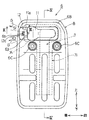
図2は、エンジンの一部を切欠いてマフラ6の部分を拡大して示す平面図である。マフラ6は、ステンレスなどの金属板からなる2つのカップ状の第1および第2ボディ半体6A,6Bを結合させて、全体が中空のほぼ直方体形状に形成されたボディBを有しており、ボディBの内部が排気室とされる。マフラカバー60のエンジン後部側には、排気ガスGを外部に排出する排出口60aが形成され、マフラカバー60のほぼ全面にわたって、放熱のための複数のスリット60b(図1)が形成されている。
FIG. 2 is an enlarged plan view showing a portion of the
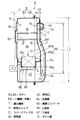
図3はマフラ6の右側面図、図4は図3のIV−IV線に沿った断面図である。マフラ6に
は、図4に示す第1ボディ半体6Aの左側の側壁6Vに、シリンダ3からの排気ガスGを第1,第2ボディ半体6A,6B内の排気室61に導入する導入口62が設けられ、第2ボディ半体6Bの外壁6Wの右側上部にはエンジン後方に向かって開口する排気ガスGの排気口63が形成されている( 図3) 。また、前記第1,第2ボディ半体6A,6Bには、その内部の排気室61を上下に区画する横方向に延びる区画壁64が設けられ、この区画壁64に、排気ガスを浄化する例えば白金のような酸化触媒65aとこれを担持するハニカムコアのような担持体65bとからなる触媒コンバータ65が縦向きに取り付けられ、これら区画壁64と触媒コンバータ65により、前記排気室61が、排気上流側の上流室66と排気下流側の下流室67とに上下に区画されている。
3 is a right side view of the
前記触媒コンバータ65は、上流室および下流室66,67に臨む入口65cおよび出口65dがそれぞれ開放されていて、図4の矢印で示すように、上流室66に導入された排気ガスGが、触媒コンバータ65の酸化触媒65aと接触して酸化したのち下流室67へと送られる。ボディBの上部には、マフラ6をシリンダ3に結合するためのボルトが挿通されるパイプ6Cが取り付けられている。パイプ6Cは、図3に示すように、左右一対設けられている。
In the
図4に示す前記下流室67の内部で触媒コンバータ65の出口65dに近接した位置には衝突板68が設けられており、この衝突板68に触媒コンバータ65からの排気ガスGを衝突させて、排気ガスGを下流室67の内部で拡散させたのち排気口63へと導くことにより、排気ガスGの消音効果を高めている。衝突板68は、支持脚69を介して触媒コンバータ65側に支持されている。
A
前記第2ボディ半体6Bの内部には、図4のように、前記下流室67の上下方向中間部から上流室66の上部側にまで延び、上端が前記排気口63に連通する導出通路7が形成されている。この導出通路7の側壁は、前記第2ボディ半体6Bの右側の一側壁6Wと、この一側壁6Wに接合される上下方向に延びるダクト壁71とにより形成されている。このとき、導出通路7を通過する排気ガスGに対し十分な冷却効果を与えるため、導出通路7の長さL1は、ボディBの上下方向長さをL2としたとき、L2の1 /2よりも長く( L1>1/2L2) 設定することが好ましい。
As shown in FIG. 4, the
図5は前記ダクト壁71を図4の左方向から見た拡大側面図、図6は図5のVI―VI線に
沿った拡大断面図である。図5に示すダクト壁71はステンレスのような金属の板材をプレス成形したもので、前記第2ボディ半体6Bの一側壁6Wに沿って延びて、この一側壁6Wとの間に導出通路7を形成するための凹部72が形成され、その周囲全体には前記一側壁6Wに溶接より接合させるための鍔片73が形成されている。前記ダクト壁71の上部には、後述する排気キャップ11(図3)と対向状にエンジン後方に向かって延びる延出片74が鍔片73と連続状に形成され、また、前記凹部72の上部の排気下流側には、幅広の拡張部75が凹部72と連続状に形成されている。凹部72の幅、つまり導出通路7の幅Wは流れ方向(上下方向)に沿ってほぼ一定であるか、導出通路7を通過する排気ガスGの流速を速めて、外部の空気の吸込みを防止しながら排気ガスGを外部にスムーズに排出させるために、図6に示すように、導出通路7の排気上流側の高さH1よりも、排気下流側の高さH2が低くなるように、つまり導出通路7の下流側の断面積が上流側の断面積に対して小さくなるように設定されている。
5 is an enlarged side view of the
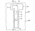
図7は、図4に示す導出通路7の上部部分の拡大断面図である。前記第2ボディ半体6Bの一側壁6Wには、前記ダクト壁71に形成した拡張部75との対向部位に、排気ガスGを前記一側壁6Wの外面に沿って流出させる排気キャップ11が、絞り加工により、外方に向かって凸状に一体形成されている。この排気キャップ11の先端側には、図3に示すように、排気ガスGを外部に排出させるための前記排気口63が形成されている。図7の一側壁6Wにおけるダクト壁71との対向部位で排気キャップ11の形成部位の上下部分には、外側(図7の右側)へ凹入した凹み部が形成されて、ダクト壁71との間に、スパークアレスタ12を保持するためのスリット6aが設けられている。
FIG. 7 is an enlarged cross-sectional view of an upper portion of the
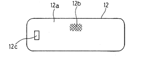
図8はスパークアレスタ12の正面図である。このスパークアレスタ12は、細長い板材からなるフレーム12aに多数の網目を持つ網材12bを接合して形成され、その長さ方向一端には、スパークアレスタ12の係止孔12cが形成されている。
FIG. 8 is a front view of the
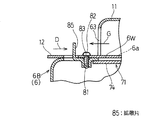
図9はスパークアレスタ12の係止構造を示す図3のIV―IV線に沿った拡大断面図であ
る。第2ボディ半体6Bの一側壁6Wには、前記係止孔12cに対応する突部6bが、切り起こしにより、外方に向かって一体に形成され、スパークアレスタ12を矢印D方向に押して前記スリット6a(図7)に挿通するときに、前記突部6bを係止孔12cに係止させることにより、スパークアレスタ12をダクト壁71の延出片74と排気キャップ11の間に介在させて保持させる。また、排気キャップ11の先端側には、一側壁6Wに向かって突出し、排気ガスGを排気口63の開口方向に対し、その周囲に拡散させるための拡散片11aが排気キャップ11と一体に形成されている。この拡散片11aは、図4に示すように、排気口63の上下方向の中央付近に位置している。
FIG. 9 is an enlarged cross-sectional view taken along the line IV-IV in FIG. 3 showing the locking structure of the
次に、以上の構成による作用について説明する。図4に示すシリンダ3からの排気ガスGは、マフラ6の導入孔62から上流室66に導入されて膨脹することにより消音されたのち、触媒コンバータ65を通過し、触媒65aとの接触により未燃焼ガスが燃焼して、HCおよびCOの濃度が低減される。触媒コンバータ65から出た排気ガスGは、衝突板68と衝突して下流室67に入り、ここでも膨脹して消音される。
Next, the effect | action by the above structure is demonstrated. Exhaust gas G from the
下流室67に入った排気ガスGは、導出通路7の下端の導入口7aから導出通路7に入り、排気キャップ11の排気口63へと導かれる。このとき、導出通路7は、ダクト壁71と第2ボディ半体6Bの一側壁6Wの一部とにより形成され、このボディ半体6Bの一側壁6Wは外気に接触しているので、一側壁6Wにより排気ガスGの熱が外気に放出されて、排気ガスGが冷却される。また、前記導出通路7の長さL1をボディBの上下方向長さL2に対しL1>(1/2)L2となるように設定することにより、導出通路7が長くなって、排気ガスGが十分に冷却される。さらに、導出通路7が長いために排気口63から外部の空気がボディB内方の排気室61の下流室67に吸い込まれるのを防止できる。
The exhaust gas G that has entered the
また、導出通路7を形成するダクト壁71の凹部72を、下流室67に臨む導出通路7での排気上流側の高さH1に対し、上流室66に臨む導出通路7での排気下流側の高さH2が低くなるように設定することにより、導出通路7の排気下流側が絞られることになる。このため、導出通路7を通過する排気ガスGの流速が上り、排気ガスGに脈動などが発生しても、排気口63からの吸込みによる外部空気の逆流が防止され、排気ガスGがスムーズに排出される。しかも、導出通路7は、ダクト壁71と第2ボディ半体6Bの一部とによって形成されるので、構造が簡単となり、生産コストも低下する。
Further, the
さらに、前記ダクト壁71は、上流室66の上部にまで延設されており、この上流室66には触媒コンバータ65で燃焼される以前の比較的低温の排気ガスGが存在するので、触媒コンバータ65を経て導出通路7を通る比較的高温の排気ガスGが、上流室66に臨むダクト壁71を介して放熱して冷却される。これにより、触媒コンバータ65を通過した高温の排気ガスGでも十分に冷却される。
Further, the
また、導出通路7に入った排気ガスGは、ダクト壁71の上部に凹部72と連続状に設けた拡張部75からスパークアレスタ12を通って排気キャップ11内に導入され、この排気キャップ11により排気ガスGの排気方向が排気口63に向かうように転向され、図2に示すように、第2ボディ半体6Bの一側壁6Wに沿う方向に排気口63から排出され、さらにマフラーカバー60の排出口60aからエンジン1の外部に排出される。このため、高温の排気ガスGが樹脂製のマフラカバー60に直接接触するのが防止される。このとき、排気キャップ11は、図7のように、第2ボディ半体6Bの一側壁6Wの一部に一体的に形成されているので、部品点数および生産コストが低減される。
Further, the exhaust gas G that has entered the lead-out
前記スパークアレスタ12は、第2ボディ半体6Bの一側壁6Wとダクト壁7 1との対接部位に形成されるスリット6aに挿通させ、スパークアレスタ12に形成した図9の係止孔12cを前記一側壁6Wに設けた突部6bに係止させることにより、前記スリット6aに挿通保持される。このため、スパークアレスタ12をねじなどの締結具を用いることなく保持させることができて、部品点数および生産コストが低減される。
The
さらに、図1のように、前記排気キャップ11の先端側には、拡散片11aが形成されているので、この拡散片11aにより、図3に示すように、排気ガスGが排気口63の開口方向に対して、主として上下両側へ拡散されながら、二点鎖線で示す領域S1,S2に分かれて排出される。このため、拡散片11aによる排気ガスの拡散効果により、図2のマフラカバー60の排出口60aからエンジン1の外部に排出される排気ガスGの温度が低下する。
Further, as shown in FIG. 1, a
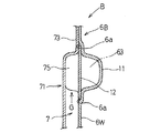
図10は本発明の第2実施形態に係るマフラを示す縦断面図である。この実施形態では、図4の場合とは異なり、第1,第2ボディ半体6A,6Bの内部の排気室61を左右に区画する縦方向に延びる区画壁64Aが設けられ、この区画壁64Aに横向きに触媒コンバータ65が取り付けられ、これら区画壁64Aと触媒コンバータ65により、前記排気室61が、上流室66Aと下流室67Aとに左右に区画されている。この実施形態の場合にも、第2ボディ半体6Bの内部に、図4の場合と同様に、第2ボディ半体6Bの右側の一側壁6Wと、これに接合されるダクト壁71Aとで構成される導出通路7Aが設けられる。このダクト壁71Aは、前記下流室67A、つまり触媒コンバータ65を通過した排気ガスGの高温領域に配置されるので、ダクト壁71Aの内部の導出通路7Aを通る排気ガスGに対し十分な冷却効果を付与するために、図4の場合よりも導出通路7Aが長くなるように設定される。
FIG. 10 is a longitudinal sectional view showing a muffler according to the second embodiment of the present invention. In this embodiment, unlike the case of FIG. 4, a
図11は前記ダクト壁71Aを左方向から見た拡大側面図である。このダクト壁71Aの凹部72Aは、導出通路7Aを、その下部から折り返して、排気ガスの拡張部75Aの近くまで上方に向かって延びる延長部72Bを有しており、全体として概略U字形状となっている。前記延長部72Bの上端に下流室67A(図10)の上部側に開口する排気ガスGの導入口7bが形成されている。
FIG. 11 is an enlarged side view of the
図12は排気口63の近傍を示す図3に対応した拡大断面図である。マフラ6の第2ボディ半体6Bの一側壁6Wには、スパークアレスタ係止用のバーリング部81が形成されている。スパークアレスタ12を矢印D方向に押して前記スリット6a(図7)に挿入したのち、タッピングスクリュー82を、スパークアレスタ12に設けた挿通孔83に挿通してバーリング部81にねじ込むことにより、スパークアレスタ12をマフラ6に固定する。この固定ののち、第2ボディ半体6Bの一側壁6Wの一部を、一側壁6Wにほぼ直交する姿勢に切り起こして、スパークアレスタ12の外方に突出させることにより、排気口63からの排気ガスGを拡散させる拡散片85を形成する。この拡散片85は、排気キャップ11の排気口63の前方に配置され、かつ、図10に示すように、排気口63の上下方向の中央付近に位置している。
FIG. 12 is an enlarged cross-sectional view corresponding to FIG. On one
前記シリンダ3からの排気ガスGは、図10の矢印で示すように、マフラ6内の左側の上流室66Aに導入されて触媒コンバータ65を通り、これを通過した排気ガスGは、衝突板68と衝突して右側の下流室67Aに入る。下流室67Aに入った排気ガスGは、図11のダクト壁71Aの延長部72Bの上端に形成した導入口7bからダクト壁71A内の導出通路7Aに導入される。導入された排気ガスGは、導出通路7AをU字状に迂回しながら拡張部75Aから排気キャップ11の内部および排気口63を経て外部に排出される。このとき、排気ガスGの導出通路7Aは、ダクト壁71Aに延長部70を追加して形成することにより、長いガス通路が確保され、ボディ半体6Bの一側壁6Wによる放熱面積が増大しているので、導出通路7Aを触媒コンバータ65を通過した下流室67A、つまり排気ガスGの高温領域に配置しているにもかかわらず、排気ガスGの良好な冷却が図れる。
The exhaust gas G from the
6 ボディ
6W 一側壁
11 排気キャップ
11a,85 拡散片
12 スパークアレスタ
61 排気室
63 排気口
64,64A 区画壁
65 触媒コンバータ
66 上流室
67 下流室
7,7A 導出通路
71,71A ダクト壁
6
Claims (4)
排気室を形成するボディの内部に、排気ガスの排気口に連通する導出通路が設けられ、
前記導出通路の側壁は、前記ボディの一部と、ボディに接合されたダクト壁とにより形成され、前記ダクト壁が横断面で前記導出通路を形成する凹部と、前記凹部の両側に位置して前記ボディの一部に取り付けられている鍔部とを有し、
前記ボディの内部に、排気ガスを浄化する触媒コンバータと、前記触媒コンバータを支持し、前記排気室を前記触媒コンバータの上部に位置する上流室と下部に位置する下流室とに区画する横方向に延びる区画壁とが設けられ、上下方向に延びる前記導出通路の下端である導入口が前記下流室に位置し、前記ダクト壁が前記上流室の上部にまで延設され、
前記導出通路の長さL1が前記ボディの上下方向長さL2に対しL1>(1/2)L2となるように設定されている小型エンジンのマフラ。 A muffler that silences engine exhaust,
Inside the body forming the exhaust chamber, a lead-out passage communicating with the exhaust gas exhaust port is provided,
A side wall of the lead-out passage is formed by a part of the body and a duct wall joined to the body, and the duct wall is located on both sides of the concave portion, the concave portion forming the lead-out passage in a cross section. Having a collar part attached to a part of the body,
A catalytic converter that purifies exhaust gas inside the body, and supports the catalytic converter, and in a lateral direction that divides the exhaust chamber into an upstream chamber located above the catalytic converter and a downstream chamber located below. An extending partition wall is provided, an inlet that is a lower end of the outlet passage extending in the vertical direction is located in the downstream chamber, and the duct wall extends to an upper portion of the upstream chamber,
A muffler for a small engine in which the length L1 of the lead-out passage is set so that L1> (1/2) L2 with respect to the length L2 in the vertical direction of the body .
Priority Applications (2)
| Application Number | Priority Date | Filing Date | Title |
|---|---|---|---|
| JP2004146491A JP4444730B2 (en) | 2004-05-17 | 2004-05-17 | Small engine muffler |
| US11/114,497 US7407036B2 (en) | 2004-05-17 | 2005-04-26 | Muffler for compact combustion engines |
Applications Claiming Priority (1)
| Application Number | Priority Date | Filing Date | Title |
|---|---|---|---|
| JP2004146491A JP4444730B2 (en) | 2004-05-17 | 2004-05-17 | Small engine muffler |
Publications (3)
| Publication Number | Publication Date |
|---|---|
| JP2005325808A JP2005325808A (en) | 2005-11-24 |
| JP2005325808A5 JP2005325808A5 (en) | 2006-12-28 |
| JP4444730B2 true JP4444730B2 (en) | 2010-03-31 |
Family
ID=35308342
Family Applications (1)
| Application Number | Title | Priority Date | Filing Date |
|---|---|---|---|
| JP2004146491A Active JP4444730B2 (en) | 2004-05-17 | 2004-05-17 | Small engine muffler |
Country Status (2)
| Country | Link |
|---|---|
| US (1) | US7407036B2 (en) |
| JP (1) | JP4444730B2 (en) |
Families Citing this family (12)
| Publication number | Priority date | Publication date | Assignee | Title |
|---|---|---|---|---|
| DE202006013280U1 (en) * | 2006-08-30 | 2008-02-07 | Dolmar Gmbh | Silencer with gill outlet |
| TWM333469U (en) * | 2007-09-12 | 2008-06-01 | Sentec E & Amp E Co Ltd | The improvement of the positioning fitting for the catalyst tubular core |
| WO2010021016A1 (en) * | 2008-08-16 | 2010-02-25 | 加藤 博子 | Exhaust gas purification apparatus |
| JP2012002082A (en) * | 2010-06-14 | 2012-01-05 | Daimler Ag | Exhaust gas purifying catalyst device and exhaust emission control device |
| JP5621975B2 (en) * | 2010-10-30 | 2014-11-12 | 日立工機株式会社 | Muffler and engine working machine equipped with the muffler |
| JP2013007317A (en) * | 2011-06-24 | 2013-01-10 | Hitachi Koki Co Ltd | Engine working machine |
| JP6084487B2 (en) * | 2013-03-11 | 2017-02-22 | 本田技研工業株式会社 | Muffler with catalytic converter |
| JP5960648B2 (en) * | 2013-06-10 | 2016-08-02 | 株式会社丸山製作所 | Muffler for portable engine |
| WO2018155071A1 (en) * | 2017-02-23 | 2018-08-30 | 工機ホールディングス株式会社 | Muffler and engine-powered working machine with same |
| WO2019082598A1 (en) * | 2017-10-26 | 2019-05-02 | 工機ホールディングス株式会社 | Muffler and engine work machine equipped with same |
| US11608762B2 (en) * | 2019-06-17 | 2023-03-21 | Tenneco Automotive Operating Company Inc. | Vehicle exhaust system |
| JP2022163291A (en) * | 2021-04-14 | 2022-10-26 | 株式会社やまびこ | Muffler for laminar scavenging engine |
Family Cites Families (16)
| Publication number | Priority date | Publication date | Assignee | Title |
|---|---|---|---|---|
| US3798769A (en) * | 1972-01-25 | 1974-03-26 | Mc Culloch Corp | Apparatus for reducing the operating noise of a chain saw |
| US4854417A (en) * | 1987-08-03 | 1989-08-08 | Honda Giken Kogyo Kabushiki Kaisha | Exhaust muffler for an internal combustion engine |
| JP2730738B2 (en) * | 1987-12-08 | 1998-03-25 | アンドレアス シュティール | Exhaust silencer for two-cycle engine |
| JPH06575Y2 (en) * | 1988-06-16 | 1994-01-05 | 川崎重工業株式会社 | Muffler for internal combustion engine |
| AU615389B2 (en) * | 1989-08-30 | 1991-09-26 | Mitsubishi Jukogyo Kabushiki Kaisha | Muffler for industrial engine |
| DE29609405U1 (en) * | 1996-05-25 | 1996-08-14 | Stihl Maschf Andreas | Exhaust silencer for internal combustion engines |
| JP3816581B2 (en) * | 1996-06-21 | 2006-08-30 | 株式会社共立 | Muffler for internal combustion engine |
| JP2989791B2 (en) * | 1997-11-19 | 1999-12-13 | 川崎重工業株式会社 | Small general-purpose engine muffler |
| JP3930961B2 (en) * | 1998-01-27 | 2007-06-13 | 株式会社共立 | Muffler for internal combustion engine |
| JP3814081B2 (en) * | 1998-06-30 | 2006-08-23 | 新ダイワ工業株式会社 | Engine muffler |
| DE19834822A1 (en) * | 1998-08-01 | 2000-02-03 | Stihl Maschf Andreas | Exhaust silencer with a catalytic converter |
| SE0001465L (en) * | 2000-04-20 | 2001-10-21 | Electrolux Ab | Silencer |
| DE60035529T2 (en) * | 2000-11-03 | 2008-03-13 | Husqvarna Ab | EXHAUST SILENCER FOR AN INTERNAL COMBUSTION ENGINE |
| JP2002242666A (en) | 2001-02-16 | 2002-08-28 | Ishikawajima Shibaura Mach Co Ltd | Muffler structure for small engine |
| US6789644B2 (en) * | 2001-11-06 | 2004-09-14 | Hiraoka Manufacturing Co., Ltd. | Engine muffler |
| DE10304326A1 (en) * | 2003-02-04 | 2004-08-12 | Andreas Stihl Ag & Co. Kg | muffler assembly |
-
2004
- 2004-05-17 JP JP2004146491A patent/JP4444730B2/en active Active
-
2005
- 2005-04-26 US US11/114,497 patent/US7407036B2/en active Active
Also Published As
| Publication number | Publication date |
|---|---|
| US7407036B2 (en) | 2008-08-05 |
| US20050252715A1 (en) | 2005-11-17 |
| JP2005325808A (en) | 2005-11-24 |
Similar Documents
| Publication | Publication Date | Title |
|---|---|---|
| US7407036B2 (en) | Muffler for compact combustion engines | |
| US7296657B2 (en) | Engine exhaust muffler with exhaust emission control function | |
| JP3930961B2 (en) | Muffler for internal combustion engine | |
| JP3816581B2 (en) | Muffler for internal combustion engine | |
| JP3863939B2 (en) | 2-cycle engine muffler | |
| US6109026A (en) | Muffler with catalytic converter | |
| US7156202B2 (en) | Method and apparatus for venting exhaust gas from an engine | |
| JP4024127B2 (en) | Exhaust device for internal combustion engine | |
| JP2009008088A (en) | High performance exhaust system | |
| US20040154289A1 (en) | Muffler assembly | |
| JP4551781B2 (en) | Exhaust muffler | |
| JP2705795B2 (en) | Silencer for internal combustion engine of portable engine driven tool | |
| JP3256685B2 (en) | Engine exhaust silencer | |
| JP3955291B2 (en) | Muffler with catalyst for internal combustion engine | |
| JP3499736B2 (en) | Muffler for internal combustion engine | |
| JP2002242666A (en) | Muffler structure for small engine | |
| JP2005240711A (en) | Exhaust emission control device of internal combustion engine | |
| JP3499741B2 (en) | Muffler for internal combustion engine | |
| JP3932852B2 (en) | Automobile exhaust system structure | |
| JPS645049Y2 (en) | ||
| US7617675B2 (en) | Catalyst chamber | |
| JP2007177693A (en) | Heat insulation structure of exhaust manifold | |
| JPH09273416A (en) | Muffler for two-cycle engine | |
| JPH0344997Y2 (en) | ||
| JPH0143450Y2 (en) |
Legal Events
| Date | Code | Title | Description |
|---|---|---|---|
| A521 | Request for written amendment filed |
Free format text: JAPANESE INTERMEDIATE CODE: A523 Effective date: 20061108 |
|
| A621 | Written request for application examination |
Free format text: JAPANESE INTERMEDIATE CODE: A621 Effective date: 20061108 |
|
| A977 | Report on retrieval |
Free format text: JAPANESE INTERMEDIATE CODE: A971007 Effective date: 20090528 |
|
| A131 | Notification of reasons for refusal |
Free format text: JAPANESE INTERMEDIATE CODE: A131 Effective date: 20090714 |
|
| A521 | Request for written amendment filed |
Free format text: JAPANESE INTERMEDIATE CODE: A523 Effective date: 20090908 |
|
| A131 | Notification of reasons for refusal |
Free format text: JAPANESE INTERMEDIATE CODE: A131 Effective date: 20091013 |
|
| A521 | Request for written amendment filed |
Free format text: JAPANESE INTERMEDIATE CODE: A523 Effective date: 20091209 |
|
| TRDD | Decision of grant or rejection written | ||
| A01 | Written decision to grant a patent or to grant a registration (utility model) |
Free format text: JAPANESE INTERMEDIATE CODE: A01 Effective date: 20100112 |
|
| A01 | Written decision to grant a patent or to grant a registration (utility model) |
Free format text: JAPANESE INTERMEDIATE CODE: A01 |
|
| A61 | First payment of annual fees (during grant procedure) |
Free format text: JAPANESE INTERMEDIATE CODE: A61 Effective date: 20100114 |
|
| R150 | Certificate of patent or registration of utility model |
Ref document number: 4444730 Country of ref document: JP Free format text: JAPANESE INTERMEDIATE CODE: R150 Free format text: JAPANESE INTERMEDIATE CODE: R150 |
|
| FPAY | Renewal fee payment (event date is renewal date of database) |
Free format text: PAYMENT UNTIL: 20130122 Year of fee payment: 3 |
|
| FPAY | Renewal fee payment (event date is renewal date of database) |
Free format text: PAYMENT UNTIL: 20130122 Year of fee payment: 3 |
|
| FPAY | Renewal fee payment (event date is renewal date of database) |
Free format text: PAYMENT UNTIL: 20140122 Year of fee payment: 4 |
|
| FPAY | Renewal fee payment (event date is renewal date of database) |
Free format text: PAYMENT UNTIL: 20150122 Year of fee payment: 5 |
|
| S111 | Request for change of ownership or part of ownership |
Free format text: JAPANESE INTERMEDIATE CODE: R313111 |
|
| R350 | Written notification of registration of transfer |
Free format text: JAPANESE INTERMEDIATE CODE: R350 |