JP4551781B2 - Exhaust muffler - Google Patents
Exhaust muffler Download PDFInfo
- Publication number
- JP4551781B2 JP4551781B2 JP2005024548A JP2005024548A JP4551781B2 JP 4551781 B2 JP4551781 B2 JP 4551781B2 JP 2005024548 A JP2005024548 A JP 2005024548A JP 2005024548 A JP2005024548 A JP 2005024548A JP 4551781 B2 JP4551781 B2 JP 4551781B2
- Authority
- JP
- Japan
- Prior art keywords
- exhaust
- sound absorbing
- punching plate
- pipe
- partition wall
- Prior art date
- Legal status (The legal status is an assumption and is not a legal conclusion. Google has not performed a legal analysis and makes no representation as to the accuracy of the status listed.)
- Active
Links
Images


Classifications
-
- A—HUMAN NECESSITIES
- A47—FURNITURE; DOMESTIC ARTICLES OR APPLIANCES; COFFEE MILLS; SPICE MILLS; SUCTION CLEANERS IN GENERAL
- A47C—CHAIRS; SOFAS; BEDS
- A47C7/00—Parts, details, or accessories of chairs or stools
- A47C7/36—Support for the head or the back
- A47C7/40—Support for the head or the back for the back
-
- A—HUMAN NECESSITIES
- A47—FURNITURE; DOMESTIC ARTICLES OR APPLIANCES; COFFEE MILLS; SPICE MILLS; SUCTION CLEANERS IN GENERAL
- A47C—CHAIRS; SOFAS; BEDS
- A47C31/00—Details or accessories for chairs, beds, or the like, not provided for in other groups of this subclass, e.g. upholstery fasteners, mattress protectors, stretching devices for mattress nets
- A47C31/10—Loose or removable furniture covers
- A47C31/11—Loose or removable furniture covers for chairs
Description
この発明は自動2輪車等に使用される内燃機関用の排気マフラーに関する。 The present invention relates to an exhaust muffler for an internal combustion engine used in a motorcycle or the like.
内部を隔壁により複数の膨張室に区画し、各膨張室間を小径の連通管で接続して排気経路を長くし、かつ膨張を反復することにより排気音エネルギーを減衰して消音する内燃機関用の排気マフラー構造が知られている。また、隔壁に多数の小孔を設け、これに排気ガスを通過させることにより大きな排気音エネルギーの減衰を生じさせるようにして、排気音の低減を図るようにしたものもある。
ところで隔壁に多数の小孔を設ける上記構造の場合、排気ガスがこの隔壁の小孔を通過することにより、排気音エネルギーを減衰させて排気音を低減させることができるが、排気抵抗が増大するので出力に影響を生じる場合がある。
そこで本願は排気抵抗を増大させることなく排気音エネルギーを低減させて排気音を効率的に低減させることを目的とする。
By the way, in the case of the above structure in which a large number of small holes are provided in the partition wall, the exhaust gas passes through the small holes in the partition wall, so that the exhaust sound energy can be attenuated to reduce the exhaust sound, but the exhaust resistance increases. This may affect the output.
In view of this, the present application aims to reduce exhaust noise energy without increasing exhaust resistance and to efficiently reduce exhaust noise.
上記課題を解決するため本願発明の排気マフラーに係る請求項1の発明は、内燃機関から延びる排気管の下流側に接続され、内部を隔壁により隔てて複数の膨張室を形成し、膨張室間をつなぐ連通管を備えた排気マフラーにおいて、
前記連通管が備えられた前記隔壁に前記排気管の開口端部に対向して多孔の吸音構造を設けたことを特徴とする。
In order to solve the above problems, the invention according to
The partition wall provided with the communication pipe is provided with a porous sound absorbing structure facing the open end of the exhaust pipe.
また、前記多孔の吸音構造が、パンチングプレートにより形成されるとともに、このパンチングプレートは前記隔壁の前方側へ配置され、かつこのパンチングプレートと前記隔壁の表面との間に空間を有することを特徴とする。
Further , the porous sound absorbing structure is formed by a punching plate, the punching plate is disposed on the front side of the partition wall, and has a space between the punching plate and the surface of the partition wall. To do.
さらに、前記パンチングプレートは中央が前方に凸となる円弧状断面で、前記排気管の開口端部に対向する部分が最も前方へ突出する最突出部をなすとともにこの最突出部から外周側へ離れるにしたがって前記隔壁へ近接する形状をとり、外周部で隔壁へ接続し、前記排気管の開口端部における開口径よりも、パンチングプレートに設けられる前記吸音構造を構成する吸音孔の径がより小さく形成されるすることを特徴とする。
Furthermore, the punching plate has an arc-shaped cross section with a center projecting forward, and a portion facing the opening end of the exhaust pipe forms the most projecting portion projecting most forward and away from the most projecting portion to the outer peripheral side. The shape of the sound absorbing hole constituting the sound absorbing structure provided in the punching plate is smaller than the diameter of the opening at the opening end of the exhaust pipe. It is characterized by being formed .
請求項2は上記請求項1において、前記パンチングプレートにおける、前記排気管の開口端部に対向する位置の中心部から離れた位置に貫通部を設け、ここに前記連通管を貫通させて開口させたことを特徴とする。
In the second aspect the first aspect, in the punching plate, the through portion is provided at a position away from the center of the position opposed to the open end of the exhaust pipe, here by through the communicating pipe is opened It is characterized by that.
請求項1の発明によれば、連通管を備えた隔壁に、排気管の開口端部に対向して多孔の吸音構造を設けたので、排気ガス流が多孔の吸音構造へ接触することにより、排気音エネルギーが減衰される。このとき吸音構造の多孔部は排気ガスを通過させるためのものではないから、吸音構造による流動抵抗がほとんど発生せず、排気抵抗を増やさないので、出力に影響を与えずにかつ効果的に排気音のエネルギーを減衰して、排気音を低減できる。 According to the first aspect of the present invention, the partition provided with the communication pipe is provided with the porous sound absorbing structure facing the opening end of the exhaust pipe, so that the exhaust gas flow comes into contact with the porous sound absorbing structure, Exhaust sound energy is attenuated. At this time, since the porous part of the sound absorbing structure is not intended to allow exhaust gas to pass through, the flow resistance due to the sound absorbing structure hardly occurs and the exhaust resistance is not increased. Sound energy can be attenuated to reduce exhaust noise.
しかも、多孔の吸音構造が排気管の開口端部に対向する位置にあるので、最も排気音のエネルギーの大きいところに吸音構造を置き、排気音のエネルギーを効率良く減衰できる。 Moreover, since the porous sound absorbing structure is located at the position facing the opening end of the exhaust pipe, the sound absorbing structure can be placed where the energy of the exhaust sound is greatest, and the energy of the exhaust sound can be attenuated efficiently.
また、多孔の吸音構造をパンチングプレートにより容易かつ安価に形成できる。また、排気音のエネルギーの大きい場所の背後に空間を形成することにより、この空間がレゾネータ同様に機能するため、吸音効率が向上する。
In addition , a porous sound absorbing structure can be easily and inexpensively formed with a punching plate. Further, by forming a space behind a place where the energy of exhaust sound is large, this space functions in the same way as a resonator, so that sound absorption efficiency is improved.
さらに、パンチングプレートを、排気管の開口端部に対向する部分が最も前方へ突出する最突出部をなし、この最突出部から外周側へ離れるにしたがって隔壁へ近接する立体形状としたので、空間の大きさを排気音のエネルギーに応じて変化させることができるとともに、この立体形状と外周部で隔壁へ接続させることとによりパンチングプレートの剛性を確保できる。
Furthermore , the punching plate has a three-dimensional shape that has a portion that faces the opening end of the exhaust pipe that protrudes most forward, and is closer to the partition wall as it moves away from the outermost portion. Can be changed according to the energy of the exhaust sound, and the rigidity of the punching plate can be ensured by connecting the three-dimensional shape and the outer periphery to the partition wall.
請求項2の発明によれば、パンチングプレートにおける排気管の開口端部に対向する位置から離れた位置に貫通部を設け、ここに前記連通管を貫通させて開口させたので、多孔の吸音構造による吸音効果への影響を小さくして連通管を配置できる。また、排気管と連通管をそれぞれの開口が互いにずれて重ならないように配置できるので、吸音構造による排気音低減効果をより大きく発揮させることができる。 According to the invention of claim 2 , since the through portion is provided at a position away from the position facing the opening end portion of the exhaust pipe in the punching plate, and the communication pipe is opened therethrough, the porous sound absorbing structure is provided. The communication pipe can be arranged with a small influence on the sound absorption effect. Further, since the exhaust pipe and the communication pipe can be arranged so that the respective openings are not shifted and overlap each other, the exhaust noise reduction effect by the sound absorbing structure can be exhibited more greatly.
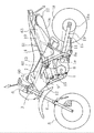
以下、図面に基づいて自動2輪車に適用された排気マフラーの実施例を説明する。図1は本願発明の適用された自動2輪車の側面を示す。エンジン1を支持する車体フレーム2はその前端部に設けられたヘッドパイプ3に左右一対のフロントフォーク4が回動自在に支持され、下端に支持された前輪5を上端部のハンドル6により操向する。
Hereinafter, an embodiment of an exhaust muffler applied to a motorcycle will be described based on the drawings. FIG. 1 shows a side view of a motorcycle to which the present invention is applied. The body frame 2 that supports the
車体フレーム2は、エンジン1の上方をヘッドパイプ3から後方へ延びるメインフレーム7と、メインフレーム7の後端部に連続してエンジン1の後方を下方へ延びるセンターフレーム8と、ヘッドパイプ3からエンジン1の前方へ斜め下がり後方へ延びるダウンフレーム9及びメインフレーム7とセンターフレーム8の接続部から斜め上がりに後方へ延びる左右一対のシートレール10並びにセンターフレーム8の下部とシートレール10の後部間を連結するリヤステー11を備える。
The vehicle body frame 2 includes a main frame 7 extending rearward from the head pipe 3 above the
メインフレーム7、センターフレーム8及びダウンフレーム9はエンジン1を支持する。エンジン1は空冷4ストローク式であり、そのシリンダヘッド12には気化器13から混合気を吸気する。符号14はエアクリーナである。また排気はシリンダヘッド12の前面側から排気管15を介して行われる。
The main frame 7, the
排気管15はシリンダヘッド12からいったん前方へ出て後方へ屈曲し、エンジン1、センターフレーム8及びリヤステー11の各側方を通って後方へ延び、シートレール10の下方に配置された排気マフラー16へ接続する。
排気マフラー16はリヤステー11とシートレール10に支持され、後端部にて斜め下向きに開口するテールパイプ17から車体後方へ排気する。
The
The
排気マフラー16の下方には後輪18が位置し、この後輪18はリヤアーム19の後端部へ支持される。リヤアーム19の前端は車体フレーム2に対して、センターフレーム8の下部に支持されたピボット軸8aにて上下方向へ揺動自在に軸支され、リヤクッション(図示省略)にて緩衝される。
A
後輪18は同軸の後輪スプロケット18aとエンジン1の出力スプロケット1a間に巻き掛けられたチェーン1bにて駆動される。図中の符号60はメインフレーム7上にて支持される燃料タンク、61はシートレール10上に支持されるタンデムシート、62は燃料タンク60の下部及びエンジン1上部の各側方を覆うシュラウド、63はタンデムシート61下方の車体左右を覆うサイドカバーであり、排気マフラー16の前端部から後端部近傍にかけて上部側の側方を覆っている。
The
図2は排気マフラー16の長さ方向断面を示す。この排気マフラー16は後方(排気下流側、以下同じ)が拡径するステンレス等からなる適宜金属製の本体筒部20と、その前後を覆うフロントキャップ21、テールキャップ22を備える。フロントキャップ21には排気管15の後端部と接続する小径のインテークパイプ23が前後方向へ貫通し、後端側はより小径の延長パイプ24に接続する。延長パイプ24は支持プレート25にて本体筒部20内に支持され、後端は本体筒部20の長さ方向略中央部近傍へ至っている。これらのインテークパイプ23及び延長パイプ24は排気管の一部を構成している。
FIG. 2 shows a longitudinal section of the
排気マフラー16内の支持プレート25よりさらに後方部分は第1隔壁26、第2隔壁27にて区画され、フロントキャップ21と第1隔壁26の間に第1膨張室29、第1隔壁26と第2隔壁27の間に第3膨張室30、第2隔壁27とテールキャップ22の間に第2膨張室31が形成される。
A portion further rearward than the
なお、支持プレート25よりも前方の空間28は、支持プレート25に設けられた開口部44(図5)により後方側の空間と連通し、単一の第1膨張室29をなす。支持プレート25については後述する。テールキャップ22は後方へ向かってすぼまる略円錐台形状をなし、その下方斜面をテールパイプ17が貫通して第3膨張室30と外気を連通している。
The
インテークパイプ23は空間28を通過し、その後端に接続する延長パイプ24は第1膨張室29後部内の略軸心部かつ第1隔壁26の前方に開口する。第1膨張室29内には第1隔壁26を貫通する第1連通管32の前端が開口する。第1連通管32は第3膨張室30を通過し、その後端は第2隔壁27を貫通して第2膨張室31内へ開口する。
The intake pipe 23 passes through the
第2膨張室31は第2隔壁27を貫通する第2連通管33を介して第3膨張室30と連通する。第2連通管33は第3膨張室30及び第2膨張室31の双方へ開口している。第3膨張室30には第2隔壁27を貫通するテールパイプ17の前端が開口する。
The
排気ガスは矢示するように、インテークパイプ23、延長パイプ24から第1膨張室29へ出て膨張し、続いて第1連通管32から後方へ流れて第2膨張室31へ出て再び膨張し、さらに第2連通管33にて前方へUターンして流れ、第3膨張室30へ出て再び膨張し、その後、再びUターンしてテールパイプ17内を後方へ流れ、外気へ排出される。34は本体筒部20に溶接されたステーであり、ここでシートレール側へ支持される。第1隔壁26にはその前面側に吸音板35が設けられている。
As shown by the arrow, the exhaust gas exits from the intake pipe 23 and the
図3は図2の第1隔壁26部分を拡大した図である。吸音板35は中央が前方へ凸の円弧状断面をなす凸曲面をなし、延長パイプ24の開口部に対面する部分であり、かつ延長パイプ24の中心軸線C上となる位置が最も前方へ凸となる、頂点状の最突出部35aになっている。この部分が排気ガス流に対向する位置の中心部をなす。この部分を含む所定範囲に多数の小孔からなる吸音孔36(指示符号は一部のみを代表的に示す)が形成されている。
FIG. 3 is an enlarged view of the
吸音板35の上部には切り欠き37が形成され、ここに第1連通管32を貫通させてその前端を前方へ突出させ、この状態で吸音板35を第1隔壁26の前面へ重ねて溶接一体化している。切り欠き37は第1連通管32の貫通部をなし、切り欠き状の他に貫通穴等が可能である。切り欠き37は吸音板35の外周部近傍に位置する。この位置は排気ガス流に対向する位置の中心部、すなわち最突出部35aから最も径方向へ離れた位置とし、第1連通管32の開口と延長パイプ24の開口とが互いに重ならないようにずらして配置されている。
A
吸音板35と第1隔壁26の間には空間40が形成される。この空間40の前後方向幅(吸音板35と第1隔壁26の表面との間隔d)は、延長パイプ24の後端開口に対面する範囲が最も拡大され、延長パイプ24から遠くなる吸音板35の外周部へ向かうほど次第に狭くなる。この空間40の前後方向幅は吸音板35の曲面に応じて連続的に変化する。吸音孔36を形成した吸音板35及び空間40は本願発明における吸音構造の一例をなす。
A
吸音板35下部には凹部38が形成され、その下方で第1隔壁26に切り欠き39が形成されている。切り欠き39は第1膨張室29と第3膨張室30を連通して液抜き穴となっている。
A
図4は図2の4−4線断面を示す。吸音板35は、上部の貫通孔37と下部の凹部38間を結ぶ直径方向に沿って多数の吸音孔36が、全体として上下方向に長い略帯状の範囲内に形成されている。吸音孔36の形成範囲は延長パイプ24から出た排気ガス流に対面する部分であり、その中心である最突出部35aを含む延長パイプ24の端部開口と対面する部分(仮想線で示す24)からその上下方向へ広がっている。
4 shows a cross section taken along line 4-4 of FIG. In the
吸音板35はパンチングメタル製であり、ロール掛けにて帯状に形成すると同時に吸音孔36を形成したパンチングプレートに対して、上方の切り欠き37及びに下方の凹部38を一体にプレス成形し、全体として前方へ凸に湾曲する凸曲面状の立体形状に成形され、適宜な金属から形成される。凹部38から見える切り欠き39は第1隔壁26の下部に円弧状をなして形成され、本体筒部20の内面との間に若干の空間を形成している。
The
吸音孔36は仮想線で示す延長パイプ24の端部開口と対面する部分に形成すれば足り、この部分に設けることがレゾネータ効果を有効に発揮する観点より好ましい。しかし、実際はパンチング成形の都合により帯状に長く分布して形成されている(パンチング範囲を図3中にAとして示す)。なお、吸音孔36の形成範囲や、吸音孔36のサイズ、個数等は任意に設定できる。
It is sufficient that the
図5は図2の5−5線断面を示す。支持プレート25は延長パイプ24が貫通する中央部41と外周部42を放射方向の連結腕部43で連結し、その間に大きな開口44が形成されている。これらの開口44により支持プレート25の前方空間28を後方の空間と連通して第1膨張室29を形成している。
FIG. 5 shows a cross section taken along line 5-5 of FIG. The
下部の連結腕部43には切り欠き39と同形・同寸の切り欠き45が液抜き穴として形成され、支持プレート25の前後の空間を連通している。
A
図6は、図2の6−6線断面を示す。第2隔壁27は直径上にて上方から下方へ第1連通管32、テールパイプ17及び第2連通管33の各開口がこの順で並び、下部には切り欠き39と同形・同寸の切り欠き46が形成されて液抜き穴となっている。
6 shows a cross section taken along line 6-6 of FIG. In the
次に本実施例の作用を説明する。図2において排気ガスがインテークパイプ23及び延長パイプ24を通して第1膨張室29内へ出て膨張する。このとき最も排気ガスの排気音エネルギーが大きい場所は、延長パイプ24の後端開口の後方となる、最突出部35aを含む吸音板35上における排気ガス流に対面する部分となる。ところで、この部分には図3に示すように、吸音孔36が形成されているため、排気ガスが吸音板35と接触することにより吸音孔36によって排気音エネルギーが減衰し、排気音が低減する。
Next, the operation of this embodiment will be described. In FIG. 2, the exhaust gas passes through the intake pipe 23 and the
このとき、図3にて明瞭に示すように、吸音板35の背面と第1隔壁26の間に空間40が形成されており、この空間40が吸音孔36を通して一種のレゾネータとして機能するから、さらに効率的に排気音を低減できる。また、この空間40の大きさは排気音のエネルギーが最も大きい排気ガス流に対面する部分の中心、すなわち最突出部35aの近傍部が最も大きく、排気音のエネルギーが小さくなる外周側にむかって次第に小さくなるから、空間40を必要な.大きさになるよう効率的に形成できる。
At this time, as clearly shown in FIG. 3, a
しかも、吸音孔36は排気ガス流に対面する部分を含んで形成されているため、最も排気音エネルギーの大きな部分のみを効率的に吸収できる。また、吸音板35が固定される第1隔壁26には第1連通管32が貫通して開口している。このため、吸音板35を設けない場合と同程度の必要な排気流量が確保されていることになり、しかも吸音板35及びその吸音孔36はほとんど排気ガスに対して排気抵抗を発生させないから、吸音板35からなる吸音構造を設けても排気抵抗を従来より増大させることもない。
Moreover, since the
そのうえ、吸音板35をパンチングプレート製としたので、多孔の吸音構造をパンチングプレートにより容易かつ安価に形成できる。また、空間40を形成するよう凸に湾曲する立体形状の曲面とすること、並びに外周部で第1隔壁26へ接続させることとにより、パンチングプレートである吸音板35の剛性も確保できる。
In addition, since the
また、吸音板35の排気流に対向する位置の中心部から離れた位置である外周部に切り欠き37を設け、ここに第1連通管32を貫通させて開口させたので、吸音効果への影響を小さくして第1連通管32を配置できる。また排気管の一部をなす延長パイプ24と第1連通管32の半径方向の位置を、互いの開口が重ならないようにずらすことになるので、吸音構造による排気音低減効果をより大きく発揮させることができる。
In addition, since the
図7は、この消音効果を示すグラフであり、横軸に排気音の周波数、縦軸に音量(dB)をとったものであり、排気音の周波数を所定範囲毎に区分し、各区分毎に測定された平均音量を示す。この図において、上側のグラフが吸音板35を設けない従来例であり、下側が本願発明である。両グラフ間の斜線部が排気音の低減程度を示す。この図より、本実施例においては比較的広い周波数範囲において排気音の低減を図ることができたことが判る。
FIG. 7 is a graph showing the silencing effect. The horizontal axis represents the exhaust sound frequency and the vertical axis represents the volume (dB). The exhaust sound frequency is divided into predetermined ranges. Shows the measured average volume. In this figure, the upper graph is a conventional example in which the
図8は別実施例に係る図3と同様部位を示す。この例では、図3における吸音構造の空間40内へグラスウール等の吸音材47を充填したものである。吸音材47はグラスウール以外にもステンレススチールウールやセラミックウール等が使用できる。また、セラミックや金属の多孔質ブロック体等の吸音材を挟んでも良い。このようにするとさらに吸音効率を上げることも可能になる。
FIG. 8 shows the same part as FIG. 3 according to another embodiment. In this example, the
図9は吸音構造に関する参考例について、図3と同様部位を示す。この例では吸音部50は、第1隔壁26より前方へ突出する多数の突起51からなる。突起51は金属等の適宜材料より第1隔壁26と一体又は別体に形成され、隣り合う突起51の間に狭い通路状をなす多数の間隙52が前方へ開放されて形成されている。
FIG. 9 shows a portion similar to FIG. 3 for a reference example regarding the sound absorbing structure . In this example, the
このようにしても、各突起51間の間隙52が多数の吸音孔36と同様に機能し、これらの間隙52を通して排気ガスが第2膨張室29と第1隔壁26の間を往復することにより排気音エネルギーを減衰させることができる。したがって、このような吸音部50も多孔の吸音構造の一例をなす。
Even in this case, the
なお、本願発明は上記の各実施例に限定されるものではなく、発明の原理内において種々に変形や応用が可能である。例えば、吸音板35を多数重ねる多重構造として、剛性を大きくしても良い。この場合には、各吸音板35間に空間を設けるようにしてよく、設けなくてもよい。また吸音板35の形成はパンチングメタルとすれば安価かつ容易に形成できるが、アルミダイキャスト等の他の任意形成方法を採用できる。また、多孔質のセラミックを配置してもよい。さらに、自動2輪車に限らず、各種内燃機関における排気マフラーに適用できる。
The present invention is not limited to the above embodiments, and various modifications and applications are possible within the principle of the invention. For example, the rigidity may be increased as a multiple structure in which many
1:エンジン、12:シリンダヘッド、15:排気管、16:排気マフラー、20:本体筒部、21:フロントキャップ、22:テールキャップ、23:インテークパイプ(排気管の一部)、24:延長パイプ(排気管の一部)、25:支持プレート、26:第1隔壁、27:第2隔壁、29:第1膨張室、30:第3膨張室、31:第2膨張室、32:第1連通管、33:第2連通管、35:吸音板、36:吸音孔、40:空間、45:開口、50:吸音部、51:突起
1: engine, 12: cylinder head, 15: exhaust pipe, 16: exhaust muffler, 20: main body cylinder, 21: front cap, 22: tail cap, 23: intake pipe (part of exhaust pipe), 24: extension Pipe (part of exhaust pipe), 25: support plate, 26: first partition, 27: second partition, 29: first expansion chamber, 30: third expansion chamber, 31: second expansion chamber, 32: second 1 communication pipe, 33: second communication pipe, 35: sound absorbing plate, 36: sound absorbing hole, 40: space, 45: opening, 50: sound absorbing portion, 51: protrusion
Claims (5)
前記連通管(32)が備えられた前記隔壁(26)に前記排気管(24)の開口端部に対向して多孔の吸音構造を設けるとともに、
この多孔の吸音構造は、パンチングプレート(35)により形成され、このパンチングプレート(35)は前記隔壁(26)の前方側へ配置され、かつこのパンチングプレート(35)と前記隔壁(26)の表面との間に空間(40)を有し、
前記パンチングプレート(35)は、中央が前方に凸となる円弧状断面で、前記排気管(24)の開口端部に対向する部分が最も前方へ突出する最突出部(35a)をなすとともにこの最突出部(35a)から外周側へ離れるにしたがって前記隔壁(26)へ近接する形状をとり、外周部で隔壁(26)へ接続し、
排気管(24)の開口端部における開口径よりも、パンチングプレート(35)に設けられる前記吸音構造を構成する吸音孔(36)の径がより小さく形成されることを特徴とする排気マフラー。 In an exhaust muffler that is connected to the downstream side of an exhaust pipe extending from an internal combustion engine, forms a plurality of expansion chambers separated by a partition wall, and includes a communication pipe that connects the expansion chambers.
The partition wall (26) provided with the communication pipe (32) is provided with a porous sound absorbing structure facing the open end of the exhaust pipe (24) , and
Sound absorbing structure of the porous is formed by punching plate (35), the surface of the punching plate (35) wherein is disposed toward the front of the partition wall (26), and this punching plate (35) bulkhead (26) A space (40) between and
The punching plate (35) has an arcuate cross section whose center is convex forward, and the portion facing the opening end of the exhaust pipe (24) forms the most projecting portion (35a) that projects forward most. takes the shape proximate said to bulkhead (26) with distance to the outer peripheral side from the protruding section (35a), connected to the partition wall (26) at the outer peripheral portion,
An exhaust muffler characterized in that the diameter of the sound absorbing hole (36) constituting the sound absorbing structure provided in the punching plate (35) is smaller than the opening diameter at the opening end of the exhaust pipe (24) .
Priority Applications (4)
| Application Number | Priority Date | Filing Date | Title |
|---|---|---|---|
| JP2005024548A JP4551781B2 (en) | 2005-01-31 | 2005-01-31 | Exhaust muffler |
| TW094146950A TW200628688A (en) | 2005-01-31 | 2005-12-28 | Exhaust muffler |
| KR1020060000927A KR100767139B1 (en) | 2005-01-31 | 2006-01-04 | Exhaust muffler |
| CN2006100012485A CN1814994B (en) | 2005-01-31 | 2006-01-10 | Exhaust silencer |
Applications Claiming Priority (1)
| Application Number | Priority Date | Filing Date | Title |
|---|---|---|---|
| JP2005024548A JP4551781B2 (en) | 2005-01-31 | 2005-01-31 | Exhaust muffler |
Publications (3)
| Publication Number | Publication Date |
|---|---|
| JP2006207562A JP2006207562A (en) | 2006-08-10 |
| JP2006207562A5 JP2006207562A5 (en) | 2008-02-14 |
| JP4551781B2 true JP4551781B2 (en) | 2010-09-29 |
Family
ID=36907334
Family Applications (1)
| Application Number | Title | Priority Date | Filing Date |
|---|---|---|---|
| JP2005024548A Active JP4551781B2 (en) | 2005-01-31 | 2005-01-31 | Exhaust muffler |
Country Status (4)
| Country | Link |
|---|---|
| JP (1) | JP4551781B2 (en) |
| KR (1) | KR100767139B1 (en) |
| CN (1) | CN1814994B (en) |
| TW (1) | TW200628688A (en) |
Families Citing this family (7)
| Publication number | Priority date | Publication date | Assignee | Title |
|---|---|---|---|---|
| CN101603445A (en) * | 2009-07-23 | 2009-12-16 | 重庆隆鑫机车有限公司 | Motorcycle |
| JP5995632B2 (en) * | 2012-09-28 | 2016-09-21 | ダイハツ工業株式会社 | Intake passage of internal combustion engine |
| CN103195549B (en) * | 2013-04-28 | 2015-11-18 | 广西工学院 | A kind of silencer muffler partition plate and silencing apparatus |
| US10971128B2 (en) * | 2015-04-10 | 2021-04-06 | Mra Systems, Llc | Acoustic liner and methods of constructing an acoustic liner |
| CN105351618B (en) * | 2015-07-08 | 2017-08-04 | 奇瑞汽车股份有限公司 | One kind expansion interference absorption-type silencer |
| JP6767711B2 (en) * | 2017-06-09 | 2020-10-14 | Smc株式会社 | Silencer and ejector using silencer |
| CN108252775A (en) * | 2018-03-19 | 2018-07-06 | 潍柴动力股份有限公司 | A kind of SCR is catalyzed silencing apparatus |
Citations (3)
| Publication number | Priority date | Publication date | Assignee | Title |
|---|---|---|---|---|
| JPH0427108U (en) * | 1990-06-26 | 1992-03-04 | ||
| JPH0471720U (en) * | 1990-07-16 | 1992-06-25 | ||
| JP2004137946A (en) * | 2002-10-17 | 2004-05-13 | Fuji Heavy Ind Ltd | Muffler |
Family Cites Families (6)
| Publication number | Priority date | Publication date | Assignee | Title |
|---|---|---|---|---|
| JPS5713373Y2 (en) * | 1977-05-26 | 1982-03-17 | ||
| JPS57114123U (en) * | 1981-01-08 | 1982-07-15 | ||
| JPH0144731Y2 (en) * | 1984-12-01 | 1989-12-25 | ||
| CN86209754U (en) * | 1986-11-28 | 1988-04-13 | 沈阳汽车消音器厂 | Damped muffler for automobile |
| KR20020094126A (en) * | 2001-06-11 | 2002-12-18 | 현대자동차주식회사 | Moving energy decentralization device of muffler |
| JP2004183622A (en) * | 2002-12-06 | 2004-07-02 | Honda Motor Co Ltd | Exhaust silencer of internal combustion engine |
-
2005
- 2005-01-31 JP JP2005024548A patent/JP4551781B2/en active Active
- 2005-12-28 TW TW094146950A patent/TW200628688A/en not_active IP Right Cessation
-
2006
- 2006-01-04 KR KR1020060000927A patent/KR100767139B1/en active IP Right Grant
- 2006-01-10 CN CN2006100012485A patent/CN1814994B/en not_active Expired - Fee Related
Patent Citations (3)
| Publication number | Priority date | Publication date | Assignee | Title |
|---|---|---|---|---|
| JPH0427108U (en) * | 1990-06-26 | 1992-03-04 | ||
| JPH0471720U (en) * | 1990-07-16 | 1992-06-25 | ||
| JP2004137946A (en) * | 2002-10-17 | 2004-05-13 | Fuji Heavy Ind Ltd | Muffler |
Also Published As
| Publication number | Publication date |
|---|---|
| TWI297056B (en) | 2008-05-21 |
| KR100767139B1 (en) | 2007-10-15 |
| CN1814994A (en) | 2006-08-09 |
| JP2006207562A (en) | 2006-08-10 |
| CN1814994B (en) | 2010-05-12 |
| TW200628688A (en) | 2006-08-16 |
| KR20060088016A (en) | 2006-08-03 |
Similar Documents
| Publication | Publication Date | Title |
|---|---|---|
| JP5909425B2 (en) | Engine exhaust system | |
| JP4551781B2 (en) | Exhaust muffler | |
| JP4684916B2 (en) | Vehicle exhaust system | |
| JP2012057610A (en) | Muffler for vehicle | |
| JP6059749B2 (en) | Exhaust muffler | |
| JP5771113B2 (en) | Exhaust silencer | |
| JP2009013902A (en) | Silencer connected to exhaust system of internal combustion engine | |
| JP2010196545A (en) | Vehicle | |
| JP2013060920A (en) | Muffling device | |
| JP5302871B2 (en) | Silencer | |
| JP4573463B2 (en) | Muffler for internal combustion engine | |
| JP5266263B2 (en) | A silencer connected to the exhaust system of an internal combustion engine | |
| JP6169035B2 (en) | Silencer structure for exhaust noise of fuel cell vehicles | |
| JP4477781B2 (en) | Silencer | |
| JP4398800B2 (en) | Engine silencer | |
| US20180202335A1 (en) | Exhaust device of engine | |
| JP3626472B2 (en) | Engine muffler and motorcycle | |
| JP3618721B2 (en) | Engine muffler and motorcycle | |
| JP2018115653A (en) | Engine exhaust system | |
| US11753973B2 (en) | Exhaust apparatus | |
| JP3809902B2 (en) | Engine muffler and motorcycle | |
| JP6468445B2 (en) | Engine exhaust silencer | |
| JP6793605B2 (en) | Engine exhaust system and motorcycle equipped with it | |
| TWI647382B (en) | Exhaust device of straddle type vehicle | |
| JPH11117723A (en) | Muffler loaded with catalyst |
Legal Events
| Date | Code | Title | Description |
|---|---|---|---|
| A521 | Written amendment |
Free format text: JAPANESE INTERMEDIATE CODE: A523 Effective date: 20071220 |
|
| A621 | Written request for application examination |
Free format text: JAPANESE INTERMEDIATE CODE: A621 Effective date: 20071220 |
|
| A131 | Notification of reasons for refusal |
Free format text: JAPANESE INTERMEDIATE CODE: A131 Effective date: 20100216 |
|
| A977 | Report on retrieval |
Free format text: JAPANESE INTERMEDIATE CODE: A971007 Effective date: 20100218 |
|
| A521 | Written amendment |
Free format text: JAPANESE INTERMEDIATE CODE: A523 Effective date: 20100419 |
|
| TRDD | Decision of grant or rejection written | ||
| A01 | Written decision to grant a patent or to grant a registration (utility model) |
Free format text: JAPANESE INTERMEDIATE CODE: A01 Effective date: 20100706 |
|
| A01 | Written decision to grant a patent or to grant a registration (utility model) |
Free format text: JAPANESE INTERMEDIATE CODE: A01 |
|
| A61 | First payment of annual fees (during grant procedure) |
Free format text: JAPANESE INTERMEDIATE CODE: A61 Effective date: 20100712 |
|
| R150 | Certificate of patent or registration of utility model |
Ref document number: 4551781 Country of ref document: JP Free format text: JAPANESE INTERMEDIATE CODE: R150 Free format text: JAPANESE INTERMEDIATE CODE: R150 |
|
| FPAY | Renewal fee payment (event date is renewal date of database) |
Free format text: PAYMENT UNTIL: 20130716 Year of fee payment: 3 |
|
| FPAY | Renewal fee payment (event date is renewal date of database) |
Free format text: PAYMENT UNTIL: 20140716 Year of fee payment: 4 |
|
| R250 | Receipt of annual fees |
Free format text: JAPANESE INTERMEDIATE CODE: R250 |