EP3677727B1 - Method and apparatus for forming a trench in a sea floor - Google Patents
Method and apparatus for forming a trench in a sea floor Download PDFInfo
- Publication number
- EP3677727B1 EP3677727B1 EP20153086.2A EP20153086A EP3677727B1 EP 3677727 B1 EP3677727 B1 EP 3677727B1 EP 20153086 A EP20153086 A EP 20153086A EP 3677727 B1 EP3677727 B1 EP 3677727B1
- Authority
- EP
- European Patent Office
- Prior art keywords
- sea floor
- trench
- displacing
- mode
- plough
- Prior art date
- Legal status (The legal status is an assumption and is not a legal conclusion. Google has not performed a legal analysis and makes no representation as to the accuracy of the status listed.)
- Active
Links
Images


Classifications
-
- E—FIXED CONSTRUCTIONS
- E02—HYDRAULIC ENGINEERING; FOUNDATIONS; SOIL SHIFTING
- E02F—DREDGING; SOIL-SHIFTING
- E02F5/00—Dredgers or soil-shifting machines for special purposes
- E02F5/02—Dredgers or soil-shifting machines for special purposes for digging trenches or ditches
- E02F5/10—Dredgers or soil-shifting machines for special purposes for digging trenches or ditches with arrangements for reinforcing trenches or ditches; with arrangements for making or assembling conduits or for laying conduits or cables
-
- E—FIXED CONSTRUCTIONS
- E02—HYDRAULIC ENGINEERING; FOUNDATIONS; SOIL SHIFTING
- E02F—DREDGING; SOIL-SHIFTING
- E02F5/00—Dredgers or soil-shifting machines for special purposes
- E02F5/02—Dredgers or soil-shifting machines for special purposes for digging trenches or ditches
- E02F5/027—Dredgers or soil-shifting machines for special purposes for digging trenches or ditches with coulters, ploughs, scraper plates, or the like
-
- E—FIXED CONSTRUCTIONS
- E02—HYDRAULIC ENGINEERING; FOUNDATIONS; SOIL SHIFTING
- E02F—DREDGING; SOIL-SHIFTING
- E02F5/00—Dredgers or soil-shifting machines for special purposes
- E02F5/02—Dredgers or soil-shifting machines for special purposes for digging trenches or ditches
- E02F5/10—Dredgers or soil-shifting machines for special purposes for digging trenches or ditches with arrangements for reinforcing trenches or ditches; with arrangements for making or assembling conduits or for laying conduits or cables
- E02F5/104—Dredgers or soil-shifting machines for special purposes for digging trenches or ditches with arrangements for reinforcing trenches or ditches; with arrangements for making or assembling conduits or for laying conduits or cables for burying conduits or cables in trenches under water
- E02F5/106—Dredgers or soil-shifting machines for special purposes for digging trenches or ditches with arrangements for reinforcing trenches or ditches; with arrangements for making or assembling conduits or for laying conduits or cables for burying conduits or cables in trenches under water using ploughs, coulters, rippers
-
- E—FIXED CONSTRUCTIONS
- E02—HYDRAULIC ENGINEERING; FOUNDATIONS; SOIL SHIFTING
- E02F—DREDGING; SOIL-SHIFTING
- E02F5/00—Dredgers or soil-shifting machines for special purposes
- E02F5/02—Dredgers or soil-shifting machines for special purposes for digging trenches or ditches
- E02F5/12—Dredgers or soil-shifting machines for special purposes for digging trenches or ditches with equipment for back-filling trenches or ditches
- E02F5/125—Dredgers or soil-shifting machines for special purposes for digging trenches or ditches with equipment for back-filling trenches or ditches underwater
-
- E—FIXED CONSTRUCTIONS
- E02—HYDRAULIC ENGINEERING; FOUNDATIONS; SOIL SHIFTING
- E02F—DREDGING; SOIL-SHIFTING
- E02F5/00—Dredgers or soil-shifting machines for special purposes
- E02F5/02—Dredgers or soil-shifting machines for special purposes for digging trenches or ditches
- E02F5/14—Component parts for trench excavators, e.g. indicating devices travelling gear chassis, supports, skids
-
- E—FIXED CONSTRUCTIONS
- E02—HYDRAULIC ENGINEERING; FOUNDATIONS; SOIL SHIFTING
- E02F—DREDGING; SOIL-SHIFTING
- E02F5/00—Dredgers or soil-shifting machines for special purposes
- E02F5/30—Auxiliary apparatus, e.g. for thawing, cracking, blowing-up, or other preparatory treatment of the soil
Definitions
- the present invention relates to apparatuses for forming a trench in a sea floor.
- European Patent Application EP 2840187 discloses an apparatus for forming a trench and burying a cable in the trench in which certain parts of the apparatus are interchangeable in order to enable the apparatus to carry out boulder clearing, first pass trenching, full depth trenching and backfilling operations.
- this arrangement suffers from the drawback that a significant number of interchangeable components are required, and the apparatus must be retrieved to the surface in order to enable conversion between at least some of the different modes of the apparatus to take place.
- Preferred embodiments of the present invention seek to overcome one or more of the above disadvantages of the prior art.
- the sea floor engaging means may be adjustable between a first mode of said sea floor engaging means, in which the sea floor engaging means engages the sea floor, and a second mode of the sea floor engaging means, in which the sea floor engaging means engages the sea floor adjacent the trench and at at least one wall of the trench.
- sea floor engaging means adjustable between a first mode of said sea floor engaging means, in which the sea floor engaging means engages the sea floor, and a second mode of the sea floor engaging means, in which the sea floor engaging means engages the sea floor adjacent the trench and at at least one wall of the trench.
- the apparatus may further comprise trench cutting means supported by the body for cutting a trench in a sea floor.
- the sea floor engaging means may comprise at least one skid.
- At least one said skid may have a first portion for engaging the sea floor in said first and second modes, and a second portion, pivotable relative to said first portion, for engaging the sea floor in said first mode and engaging a wall of the trench in said second mode.
- This provides the advantage of providing a lower cost, simplified construction of the skid, which is easy to adjust.
- the height of the sea floor engaging means may be adjustable relative to the body.
- This provides the advantage of enabling the depth of the trench cutting means to be adjusted.
- the apparatus may further comprise material displacing means for displacing material on the sea floor as a result of movement of the apparatus along the trench, wherein the material displacing means is adjustable between a first mode of the material displacing means, in which material removed from the trench is displaced laterally away from the trench, and a second mode of the material displacing means, in which material adjacent the trench is displaced into the trench.
- the material displacing means may comprise a plurality of first material displacement members pivotable between said first and second modes of the material displacement means.
- the apparatus may further comprise restraining means for restraining outward pivoting of said first material displacement members relative to the body in said second mode of the material displacing means.
- the apparatus may further comprise material displacing means for displacing material on the sea floor as a result of movement of the apparatus along the sea floor, wherein the material displacing means comprises a plurality of first material displacement members mounted to the body, and a plurality of second material displacement members mounted to the first material displacement members in a first mode of the material displacing means such that a lateral width of the apparatus in said first mode of the material displacing means is larger than the lateral with of the apparatus in a second mode of the material displacing means.
- the material displacing means for displacing material on the sea floor as a result of movement of the apparatus along the sea floor, wherein the material displacing means comprises a plurality of first material displacement members mounted to the body, and a plurality of second material displacement members mounted to the first material displacement members in a first mode of the material displacing means such that a lateral width of the apparatus in said first mode of the material displacing means is larger than the lateral with of the apparatus in a second mode of the material displacing means, this provides the advantage of ensuring more efficient operation of the apparatus by enabling debris clearance and/or backfilling to be carried out over a wider path than is covered by a trenching operation, thereby reducing the tendency of large debris to be inserted into the trench in the backfilling operation.
- the apparatus also enables the width of the apparatus during deployment from the surface to be reduced, thereby making deployment from and recovery to the surface easier.
- the apparatus may further comprise trench cutting means supported by the body for cutting a trench in the sea floor.
- At least one said second material displacement member may be pivotably mounted to a respective said first material displacement member.
- the material displacing means may further be adapted to displace material on the sea floor, forwards of the sea floor engaging means, laterally outwards of the apparatus.
- the material displacing means may be adapted to displace material by means of at least one third material displacing member mounted to said body.
- the third material displacing member may be removable.
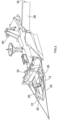
- a universal plough 2 for clearing debris such as boulders from a region of a sea floor where a trench is to be formed, and cutting part of the trench in a first pass, is shown in a debris clearing mode of the plough 2.
- the plough 2 has a body 4 having a single point lift attachment 6 for connection to a lift wire (not shown) for enabling deployment of the plough 2 to the sea floor from a surface vessel (not shown), or recovery of the plough 2 from the sea floor to the surface vessel.
- the plough is controlled by means of electrical power supplied by means of an umbilical cable (not shown).
- the body 4 supports trench cutting means in the form of a plough share 8 and a pair of fixed mouldboards 10 are located above the plough share 8 for displacing soil out of a trench formed by the plough share 8 as the plough 2 is towed forwards.
- the body 4 also supports sea floor engaging means in the form of a pair of front skids 12 pivotably mounted via links 14 to a beam 16, which is in turn pivotably mounted to the front of the body 4.
- Each of the front skids 12 can be raised and lowered relative to the body 4 by means of a respective hydraulic actuator 18, and has a fixed first part 20, and a second part 22 pivotably mounted to the first part 20, the operation of which will be described in greater detail below with reference to Figures 3 and 12 to 14.
- a debris clearing member 24 is removably attached to the front skids 12, and a towing cable 26 is attached to each end of the beam 16 to enable towing of the plough 2.
- Material displacing means includes first material displacement members in the form of a pair of pivotable mouldboards 28 pivotably mounted to the body 4 to the rear of the plough share 8 and the fixed mouldboards 10, and second material displacement members in the form of a pair of mouldboard extensions 30 pivotably mounted to the pivotable mouldboards 28.
- the pivotable mouldboards 28 are pivotable relative to the body 4 by means of hydraulic actuators 32, and the mouldboard extensions 30 are pivotable relative to the pivotable mouldboards 28 by means of hydraulic actuators 34 ( Figure 3 ).
- the body 4 is further supported on the sea floor by a pair of rear skids 36 ( Figure 3 ).
- a pair of pivotable thrusters 38, 40 enable control of the orientation of the plough 2 while it is supported by the lift wire before coming into contact with the sea bed.
- the front skids 12 of the plough 2 are pivoted relative to the body 4 into a generally vertical orientation by means of hydraulic actuators 42 connected between the front skids 12 and the links 14, to reduce the overall length of the plough 2.
- the lateral width of the plough 2 is also reduced by pivoting the mouldboard extensions 30 by means of hydraulic actuators 34 to that the mouldboard extensions are arranged in an orientation 30A ( Figure 4 ) generally parallel to a longitudinal axis 44 of the plough 2.
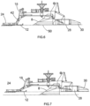
- the plough 2 is then lowered from the surface vessel to the seabed, and as it approaches the seabed, the front skids 12 together with debris clearing member 24 are lowered to a generally horizontal orientation as shown in Figure 6 by means of the hydraulic actuators 42.
- the mouldboard extensions 30 are also pivoted relative to the pivotable mouldboards 28 by means of hydraulic actuators 34 to take up the orientation 30B shown in Figure 4 , so that a front surface 46 of each pivotable mouldboard 28 generally forms a continuous surface with a front surface 48 of the corresponding mouldboard extension 30.
- the pivotable mouldboards are pivoted relative to the body 4 by means of hydraulic actuators 32 so that the pivotable mouldboards 28 and mouldboard extensions 30 are arranged at an angle ⁇ to the longitudinal axis 44, as shown in Figure 4 .
- the surface vessel (not shown) then tows the plough 2 via towing cable 26, and debris located forwards of the front skids 12 is displaced out of the path of the front skids 12 by the debris clearing member 24.
- debris is displaced laterally of the plough 2 by pivotable mouldboards 28 and mouldboard extensions 30 to form first debris heaps 52 on both sides of the plough 2.
- the plough 2 On completion of the first pass cutting of the trench by the plough 2 in the configuration shown in Figure 7 , the plough 2 is raised from the seabed 50, returned to its launch/recovery configuration shown in Figure 5 , and is then recovered to the surface vessel where the debris clearing member 24 is removed from the front skids 12.
- the mouldboard extensions 30 are either removed from the pivotable mouldboards 28 or are pivoted relative to the pivotable mouldboards 28 by means of hydraulic actuators 34 so that they are located behind the pivotable mouldboards 28.
- the plough is then in the configuration shown in Figure 9 and is returned to the seabed 50 to the trench formed in the first pass trenching operation described above.
- the front skids 12 are rotated to a generally horizontal orientation by means of the hydraulic actuators 42 to provide the configuration shown in Figure 10 .
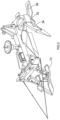
- the front skids 12 are then raised relative to the plough share 8 by means of hydraulic actuators 18 so that the plough share 8 can penetrate the seabed 50 to a greater depth than in the configuration shown in Figure 1 to enable the plough 2 to operate in its full depth trenching mode as shown in Figures 2 and 11 .
- the plough 2 is towed by the surface vessel so that second pass cutting of the trench is carried out in which the plough 8 share cuts the trench to its full depth.
- Soil displaced from the trench by the plough share 8 is displaced laterally away from the trench by fixed mouldboards 10 and then by pivotable mouldboards 28 to form second debris heaps 54 ( Figure 8 ) on both sides of the plough 2.
- the mouldboard extensions 30 do not contribute to material displacement from the trench in the full depth trenching mode, the second debris heaps 54 are located laterally inwards of the first debris heaps 52.
- a cable (not shown) to be installed in the trench is guided into the trench via guide wheels 38, 40.
- the plough 2 On completion of the full depth trenching process, the plough 2 is returned to its launch/recovery configuration as shown in Figure 9 and then recovered to the surface vessel for reattachment of the mouldboard extensions 30, if they have been removed for the full depth trenching mode, and for reconfiguration of the plough 2 to its backfilling mode as shown in Figure 3 .
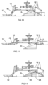
- the mouldboard extensions 30 are arranged so that the front surface 48 of each mouldboard extension 30 forms a generally continuous surface with the front surface 46 of the corresponding pivotable mouldboard 28, and the pivotable mouldboards 28 are pivoted forwards of the body 4 by means of hydraulic actuators 32 so that the pivotable mouldboards 28 and mouldboard extensions 30 are arranged at an angle ⁇ to the longitudinal axis 44 of the plough 2, to take up the orientation 28A as shown in Figure 12 .
- the angle ⁇ shown in Figure 12 is smaller than the angle ⁇ shown in Figure 4 .
- Restraining members 56 prevent the pivotable mouldboards 28 from pivoting outwards relative to the body 4 beyond the orientation 28B shown in Figure 12 .
- the front skids 12 are pivoted to a generally vertical orientation as shown in Figure 13 by means of hydraulic actuators 42 to place the plough in its launch/recovery configuration.
- the plough 2 is then returned to the seabed in its launch/recovery configuration as shown in Figure 13 , and shortly before arrival at the seabed 50, the front skids 12 are lowered to a generally horizontal orientation by means of the hydraulic actuators 42 to bring the plough 2 into a landing configuration.
- the second parts 22 of the front skids 12 are then pivoted relative to the first parts 20 to bring the front skids 12 into the configuration shown in Figure 3 .
- the front skids 12 are then located in the top of the trench so that the first parts 20 engage the seabed 50 adjacent the trench and the second parts 22 engage the upper parts of the sidewalls of the trench to more reliably locate the skids 12 in engagement with the trench as the plough 2 is towed forwards.
- the front skids 12 are then raised relative to the body 4 by means of hydraulic actuators 18 to bring the plough into the configuration shown in Figure 14 so that the plough share 8 does not enter the trench to its full depth.
- the plough 2 supported by the front skids 12 and rear skids 36, is then towed along the trench containing the cable and the pivotable mouldboards 28 together with mouldboard extensions 30 displace relatively finer soil located in the second debris heaps 54 ( Figure 12 ) into the trench to bury the cable in the trench, while leaving the first debris heaps 52, containing relatively coarser soil, generally undisturbed, since the mouldboard extensions 30 extend laterally outwards from the plough 2 to a lesser extent in the backfilling mode of Figure 3 than in the debris clearing mode of Figure 1 , because the angle ⁇ is smaller than the angle ⁇ .
Landscapes
- Engineering & Computer Science (AREA)
- Mining & Mineral Resources (AREA)
- Mechanical Engineering (AREA)
- Civil Engineering (AREA)
- General Engineering & Computer Science (AREA)
- Structural Engineering (AREA)
- Electric Cable Installation (AREA)
- Revetment (AREA)
- Bridges Or Land Bridges (AREA)
- Soil Working Implements (AREA)
Priority Applications (2)
| Application Number | Priority Date | Filing Date | Title |
|---|---|---|---|
| EP20153086.2A EP3677727B1 (en) | 2016-03-08 | 2016-03-08 | Method and apparatus for forming a trench in a sea floor |
| DK20153086.2T DK3677727T3 (da) | 2016-03-08 | 2016-03-08 | Fremgangsmåde og apparat til dannelse af en rende på havbunden |
Applications Claiming Priority (2)
| Application Number | Priority Date | Filing Date | Title |
|---|---|---|---|
| EP20153086.2A EP3677727B1 (en) | 2016-03-08 | 2016-03-08 | Method and apparatus for forming a trench in a sea floor |
| EP16159131.8A EP3216925A1 (en) | 2016-03-08 | 2016-03-08 | Method and apparatus for forming a trench in a sea floor |
Related Parent Applications (1)
| Application Number | Title | Priority Date | Filing Date |
|---|---|---|---|
| EP16159131.8A Division EP3216925A1 (en) | 2016-03-08 | 2016-03-08 | Method and apparatus for forming a trench in a sea floor |
Publications (2)
| Publication Number | Publication Date |
|---|---|
| EP3677727A1 EP3677727A1 (en) | 2020-07-08 |
| EP3677727B1 true EP3677727B1 (en) | 2024-10-09 |
Family
ID=55524176
Family Applications (2)
| Application Number | Title | Priority Date | Filing Date |
|---|---|---|---|
| EP20153086.2A Active EP3677727B1 (en) | 2016-03-08 | 2016-03-08 | Method and apparatus for forming a trench in a sea floor |
| EP16159131.8A Ceased EP3216925A1 (en) | 2016-03-08 | 2016-03-08 | Method and apparatus for forming a trench in a sea floor |
Family Applications After (1)
| Application Number | Title | Priority Date | Filing Date |
|---|---|---|---|
| EP16159131.8A Ceased EP3216925A1 (en) | 2016-03-08 | 2016-03-08 | Method and apparatus for forming a trench in a sea floor |
Country Status (7)
| Country | Link |
|---|---|
| US (1) | US10711432B2 (OSRAM) |
| EP (2) | EP3677727B1 (OSRAM) |
| JP (2) | JP2019515158A (OSRAM) |
| KR (1) | KR102631778B1 (OSRAM) |
| CA (1) | CA3017056C (OSRAM) |
| DK (2) | DK3677727T3 (OSRAM) |
| WO (1) | WO2017153184A1 (OSRAM) |
Families Citing this family (11)
| Publication number | Priority date | Publication date | Assignee | Title |
|---|---|---|---|---|
| GB2573530A (en) * | 2018-05-08 | 2019-11-13 | Atlantic Marine & Aviation Llp | Subsea clearing apparatus |
| GB2573588A (en) * | 2018-05-08 | 2019-11-13 | Atlantic Marine & Aviation Llp | Subsea apparatus |
| US11466425B2 (en) * | 2019-01-08 | 2022-10-11 | Brian Alumbaugh | Land plane |
| GB2580612B (en) | 2019-01-16 | 2021-07-07 | Osbit Ltd | Subsea plough |
| CN109997430A (zh) * | 2019-05-08 | 2019-07-12 | 中国农业科学院农业资源与农业区划研究所 | 一种土壤改良剂撒施机及其使用方法 |
| EP3800297A1 (en) | 2019-10-02 | 2021-04-07 | Soil Machine Dynamics Limited | Method and apparatus for inserting an elongate object into a trench in a sea floor |
| EP3832026B1 (en) | 2019-12-05 | 2023-07-26 | Soil Machine Dynamics Limited | Apparatus for locating elongate object in a trench in a floor of a body of water |
| EP3882401B1 (en) | 2020-03-20 | 2023-09-06 | Soil Machine Dynamics Limited | Apparatus and method for inserting an elongate object into a trench |
| CN111910699B (zh) * | 2020-07-21 | 2022-07-15 | 东至尔岛道路运输有限公司 | 一种建筑施工用具有防护限位结构的管线埋设辅助设备 |
| EP4047141A1 (en) * | 2021-02-22 | 2022-08-24 | Nexans | Top loading cable plough |
| DK4112821T3 (da) * | 2021-06-28 | 2024-12-09 | Soil Machine Dynamics Ltd | Indretning til at indsætte en aflang genstand i en grøft |
Family Cites Families (20)
| Publication number | Priority date | Publication date | Assignee | Title |
|---|---|---|---|---|
| USRE20990E (en) * | 1939-01-24 | Ditcher | ||
| US2136911A (en) * | 1937-01-07 | 1938-11-15 | Ernest V Briscoe | Ditch digger and cleaner |
| US2849809A (en) * | 1946-11-15 | 1958-09-02 | Robert C Chattin | Ditcher with divergent wings |
| US3462963A (en) | 1967-08-02 | 1969-08-26 | Brown & Root | Apparatus for pipelaying and trenching operations in a body of water |
| US3526047A (en) * | 1967-10-09 | 1970-09-01 | Edmund Roessler | Ditching machine having vertically adjustable wheels |
| GB8301515D0 (en) * | 1983-01-20 | 1983-02-23 | British Petroleum Co Plc | Trench backfill device |
| GB8331892D0 (en) * | 1983-11-30 | 1984-01-04 | Soil Machine Dynamics Ltd | Ploughs |
| GB8524410D0 (en) * | 1985-10-03 | 1985-11-06 | Soil Machine Dynamics Ltd | Pipeline/cable plough |
| GB2172032B (en) | 1985-03-09 | 1988-06-15 | Daisy D Limited | Apparatus for laying flexible drainage pipes in trenched ground |
| GB8714515D0 (en) * | 1987-06-20 | 1987-07-22 | Land & Marine Eng Ltd | Seabed trenching apparatus |
| GB9618638D0 (en) * | 1996-09-06 | 1996-10-16 | Cable & Wireless Plc | Improvements in underwater ploughing |
| WO1999013171A1 (en) * | 1997-09-05 | 1999-03-18 | Soil Machine Dynamics Limited | Submarine plough |
| GB9923964D0 (en) | 1999-10-11 | 1999-12-08 | Engineering Business Ltd | Improvements to submarine ploughs |
| RU2468154C2 (ru) | 2010-09-28 | 2012-11-27 | Всеволод Иоакимович Минаев | Траншеезасыпатель |
| WO2012151659A1 (en) * | 2011-05-06 | 2012-11-15 | Penner Jeffrey Ryan | Ditching apparatus with divergent v-wing blade configuration |
| US10323383B2 (en) * | 2012-11-30 | 2019-06-18 | Oceaneering International, Inc. | Seabed plow capable of over-the-stern release and retrieval in any of boulder clearing, trenching and backfill configurations |
| US9422690B2 (en) * | 2012-11-30 | 2016-08-23 | Michael W. N. Wilson | Method and apparatus for performing burial assessment surveys |
| EP2787126A1 (en) * | 2013-04-05 | 2014-10-08 | Soil Machine Dynamics Limited | Trench cutting apparatus |
| EP2840187A1 (en) | 2013-08-22 | 2015-02-25 | Soil Machine Dynamics Limited | Method and apparatus for forming a trench in a sea floor |
| JP6591977B2 (ja) * | 2013-11-18 | 2019-10-16 | マスファブ リミテッド | 埋設アセスメント調査を実行するための方法および装置 |
-
2016
- 2016-03-08 DK DK20153086.2T patent/DK3677727T3/da active
- 2016-03-08 EP EP20153086.2A patent/EP3677727B1/en active Active
- 2016-03-08 EP EP16159131.8A patent/EP3216925A1/en not_active Ceased
-
2017
- 2017-02-24 JP JP2018547998A patent/JP2019515158A/ja active Pending
- 2017-02-24 US US16/083,080 patent/US10711432B2/en active Active
- 2017-02-24 CA CA3017056A patent/CA3017056C/en active Active
- 2017-02-24 KR KR1020187028969A patent/KR102631778B1/ko active Active
- 2017-02-24 WO PCT/EP2017/054300 patent/WO2017153184A1/en not_active Ceased
-
2018
- 2018-09-07 DK DKPA201870577A patent/DK180329B1/en active IP Right Grant
-
2022
- 2022-02-25 JP JP2022027550A patent/JP7229403B2/ja active Active
Also Published As
| Publication number | Publication date |
|---|---|
| US20190032303A1 (en) | 2019-01-31 |
| DK180329B1 (en) | 2020-11-25 |
| EP3677727A1 (en) | 2020-07-08 |
| JP7229403B2 (ja) | 2023-02-27 |
| US10711432B2 (en) | 2020-07-14 |
| CA3017056C (en) | 2023-10-10 |
| DK3677727T3 (da) | 2025-01-06 |
| EP3216925A1 (en) | 2017-09-13 |
| KR102631778B1 (ko) | 2024-01-31 |
| KR20180121596A (ko) | 2018-11-07 |
| DK201870577A1 (en) | 2018-09-27 |
| CA3017056A1 (en) | 2017-09-14 |
| JP2019515158A (ja) | 2019-06-06 |
| JP2022060519A (ja) | 2022-04-14 |
| WO2017153184A1 (en) | 2017-09-14 |
Similar Documents
| Publication | Publication Date | Title |
|---|---|---|
| EP3677727B1 (en) | Method and apparatus for forming a trench in a sea floor | |
| EP3397816B1 (en) | Subsea plough and ploughing | |
| EP2840187A1 (en) | Method and apparatus for forming a trench in a sea floor | |
| US12163311B2 (en) | Subsea plough for burying a flexible elongate member | |
| EP4112821B1 (en) | Apparatus for inserting an elongate object into a trench | |
| EP1432877B1 (en) | Cable of pipe retrieval and burial apparatus and methods | |
| JP2023503834A (ja) | 海底に細長い要素を設けるための装置、方法、およびアセンブリ | |
| US4664553A (en) | Plough assembly | |
| AU2002327978A1 (en) | Cable of pipe retrieval and burial apparatus and methods | |
| US5707174A (en) | Underwater cable burial machine using a single cable for towing and lifting | |
| US20020071724A1 (en) | Submarine plough | |
| US3673808A (en) | Method of and apparatus for burying sub-sea pipelines,cables and the like | |
| GB2364358A (en) | Plough for laying elongate articles | |
| KR101140789B1 (ko) | 해저케이블 매설장치 | |
| WO2001075236A1 (en) | Submarine plough | |
| EP4112819A1 (en) | Apparatus for inserting an elongate object into a trench | |
| WO2001049946A1 (en) | Submarine plough |
Legal Events
| Date | Code | Title | Description |
|---|---|---|---|
| PUAI | Public reference made under article 153(3) epc to a published international application that has entered the european phase |
Free format text: ORIGINAL CODE: 0009012 |
|
| STAA | Information on the status of an ep patent application or granted ep patent |
Free format text: STATUS: REQUEST FOR EXAMINATION WAS MADE |
|
| 17P | Request for examination filed |
Effective date: 20200122 |
|
| AC | Divisional application: reference to earlier application |
Ref document number: 3216925 Country of ref document: EP Kind code of ref document: P |
|
| AK | Designated contracting states |
Kind code of ref document: A1 Designated state(s): AL AT BE BG CH CY CZ DE DK EE ES FI FR GB GR HR HU IE IS IT LI LT LU LV MC MK MT NL NO PL PT RO RS SE SI SK SM TR |
|
| STAA | Information on the status of an ep patent application or granted ep patent |
Free format text: STATUS: EXAMINATION IS IN PROGRESS |
|
| 17Q | First examination report despatched |
Effective date: 20230224 |
|
| GRAP | Despatch of communication of intention to grant a patent |
Free format text: ORIGINAL CODE: EPIDOSNIGR1 |
|
| STAA | Information on the status of an ep patent application or granted ep patent |
Free format text: STATUS: GRANT OF PATENT IS INTENDED |
|
| INTG | Intention to grant announced |
Effective date: 20240510 |
|
| GRAS | Grant fee paid |
Free format text: ORIGINAL CODE: EPIDOSNIGR3 |
|
| GRAA | (expected) grant |
Free format text: ORIGINAL CODE: 0009210 |
|
| STAA | Information on the status of an ep patent application or granted ep patent |
Free format text: STATUS: THE PATENT HAS BEEN GRANTED |
|
| AC | Divisional application: reference to earlier application |
Ref document number: 3216925 Country of ref document: EP Kind code of ref document: P |
|
| AK | Designated contracting states |
Kind code of ref document: B1 Designated state(s): AL AT BE BG CH CY CZ DE DK EE ES FI FR GB GR HR HU IE IS IT LI LT LU LV MC MK MT NL NO PL PT RO RS SE SI SK SM TR |
|
| REG | Reference to a national code |
Ref country code: CH Ref legal event code: EP |
|
| REG | Reference to a national code |
Ref country code: DE Ref legal event code: R096 Ref document number: 602016089822 Country of ref document: DE |
|
| REG | Reference to a national code |
Ref country code: IE Ref legal event code: FG4D |
|
| REG | Reference to a national code |
Ref country code: NL Ref legal event code: FP |
|
| REG | Reference to a national code |
Ref country code: DK Ref legal event code: T3 Effective date: 20250103 |
|
| REG | Reference to a national code |
Ref country code: LT Ref legal event code: MG9D |
|
| REG | Reference to a national code |
Ref country code: AT Ref legal event code: MK05 Ref document number: 1730731 Country of ref document: AT Kind code of ref document: T Effective date: 20241009 |
|
| PG25 | Lapsed in a contracting state [announced via postgrant information from national office to epo] |
Ref country code: IS Free format text: LAPSE BECAUSE OF FAILURE TO SUBMIT A TRANSLATION OF THE DESCRIPTION OR TO PAY THE FEE WITHIN THE PRESCRIBED TIME-LIMIT Effective date: 20250209 Ref country code: PT Free format text: LAPSE BECAUSE OF FAILURE TO SUBMIT A TRANSLATION OF THE DESCRIPTION OR TO PAY THE FEE WITHIN THE PRESCRIBED TIME-LIMIT Effective date: 20250210 Ref country code: HR Free format text: LAPSE BECAUSE OF FAILURE TO SUBMIT A TRANSLATION OF THE DESCRIPTION OR TO PAY THE FEE WITHIN THE PRESCRIBED TIME-LIMIT Effective date: 20241009 |
|
| PG25 | Lapsed in a contracting state [announced via postgrant information from national office to epo] |
Ref country code: FI Free format text: LAPSE BECAUSE OF FAILURE TO SUBMIT A TRANSLATION OF THE DESCRIPTION OR TO PAY THE FEE WITHIN THE PRESCRIBED TIME-LIMIT Effective date: 20241009 |
|
| PGFP | Annual fee paid to national office [announced via postgrant information from national office to epo] |
Ref country code: DK Payment date: 20250327 Year of fee payment: 10 Ref country code: NL Payment date: 20250328 Year of fee payment: 10 |
|
| P01 | Opt-out of the competence of the unified patent court (upc) registered |
Free format text: CASE NUMBER: APP_11157/2025 Effective date: 20250306 |
|
| PG25 | Lapsed in a contracting state [announced via postgrant information from national office to epo] |
Ref country code: BG Free format text: LAPSE BECAUSE OF FAILURE TO SUBMIT A TRANSLATION OF THE DESCRIPTION OR TO PAY THE FEE WITHIN THE PRESCRIBED TIME-LIMIT Effective date: 20241009 |
|
| PG25 | Lapsed in a contracting state [announced via postgrant information from national office to epo] |
Ref country code: ES Free format text: LAPSE BECAUSE OF FAILURE TO SUBMIT A TRANSLATION OF THE DESCRIPTION OR TO PAY THE FEE WITHIN THE PRESCRIBED TIME-LIMIT Effective date: 20241009 |
|
| PGFP | Annual fee paid to national office [announced via postgrant information from national office to epo] |
Ref country code: IE Payment date: 20250327 Year of fee payment: 10 |
|
| PGFP | Annual fee paid to national office [announced via postgrant information from national office to epo] |
Ref country code: NO Payment date: 20250328 Year of fee payment: 10 |
|
| PG25 | Lapsed in a contracting state [announced via postgrant information from national office to epo] |
Ref country code: LV Free format text: LAPSE BECAUSE OF FAILURE TO SUBMIT A TRANSLATION OF THE DESCRIPTION OR TO PAY THE FEE WITHIN THE PRESCRIBED TIME-LIMIT Effective date: 20241009 Ref country code: GR Free format text: LAPSE BECAUSE OF FAILURE TO SUBMIT A TRANSLATION OF THE DESCRIPTION OR TO PAY THE FEE WITHIN THE PRESCRIBED TIME-LIMIT Effective date: 20250110 Ref country code: AT Free format text: LAPSE BECAUSE OF FAILURE TO SUBMIT A TRANSLATION OF THE DESCRIPTION OR TO PAY THE FEE WITHIN THE PRESCRIBED TIME-LIMIT Effective date: 20241009 |
|
| PGFP | Annual fee paid to national office [announced via postgrant information from national office to epo] |
Ref country code: BE Payment date: 20250328 Year of fee payment: 10 |
|
| PG25 | Lapsed in a contracting state [announced via postgrant information from national office to epo] |
Ref country code: PL Free format text: LAPSE BECAUSE OF FAILURE TO SUBMIT A TRANSLATION OF THE DESCRIPTION OR TO PAY THE FEE WITHIN THE PRESCRIBED TIME-LIMIT Effective date: 20241009 |
|
| PGFP | Annual fee paid to national office [announced via postgrant information from national office to epo] |
Ref country code: FR Payment date: 20250328 Year of fee payment: 10 |
|
| PGFP | Annual fee paid to national office [announced via postgrant information from national office to epo] |
Ref country code: GB Payment date: 20250331 Year of fee payment: 10 |
|
| PG25 | Lapsed in a contracting state [announced via postgrant information from national office to epo] |
Ref country code: RS Free format text: LAPSE BECAUSE OF FAILURE TO SUBMIT A TRANSLATION OF THE DESCRIPTION OR TO PAY THE FEE WITHIN THE PRESCRIBED TIME-LIMIT Effective date: 20250109 |
|
| PG25 | Lapsed in a contracting state [announced via postgrant information from national office to epo] |
Ref country code: SM Free format text: LAPSE BECAUSE OF FAILURE TO SUBMIT A TRANSLATION OF THE DESCRIPTION OR TO PAY THE FEE WITHIN THE PRESCRIBED TIME-LIMIT Effective date: 20241009 |
|
| PGFP | Annual fee paid to national office [announced via postgrant information from national office to epo] |
Ref country code: DE Payment date: 20250331 Year of fee payment: 10 |
|
| REG | Reference to a national code |
Ref country code: DE Ref legal event code: R097 Ref document number: 602016089822 Country of ref document: DE |
|
| PGFP | Annual fee paid to national office [announced via postgrant information from national office to epo] |
Ref country code: IT Payment date: 20250328 Year of fee payment: 10 |
|
| PG25 | Lapsed in a contracting state [announced via postgrant information from national office to epo] |
Ref country code: EE Free format text: LAPSE BECAUSE OF FAILURE TO SUBMIT A TRANSLATION OF THE DESCRIPTION OR TO PAY THE FEE WITHIN THE PRESCRIBED TIME-LIMIT Effective date: 20241009 |
|
| PG25 | Lapsed in a contracting state [announced via postgrant information from national office to epo] |
Ref country code: RO Free format text: LAPSE BECAUSE OF FAILURE TO SUBMIT A TRANSLATION OF THE DESCRIPTION OR TO PAY THE FEE WITHIN THE PRESCRIBED TIME-LIMIT Effective date: 20241009 |
|
| PG25 | Lapsed in a contracting state [announced via postgrant information from national office to epo] |
Ref country code: SK Free format text: LAPSE BECAUSE OF FAILURE TO SUBMIT A TRANSLATION OF THE DESCRIPTION OR TO PAY THE FEE WITHIN THE PRESCRIBED TIME-LIMIT Effective date: 20241009 |
|
| PG25 | Lapsed in a contracting state [announced via postgrant information from national office to epo] |
Ref country code: CZ Free format text: LAPSE BECAUSE OF FAILURE TO SUBMIT A TRANSLATION OF THE DESCRIPTION OR TO PAY THE FEE WITHIN THE PRESCRIBED TIME-LIMIT Effective date: 20241009 |
|
| PLBE | No opposition filed within time limit |
Free format text: ORIGINAL CODE: 0009261 |
|
| STAA | Information on the status of an ep patent application or granted ep patent |
Free format text: STATUS: NO OPPOSITION FILED WITHIN TIME LIMIT |
|
| PG25 | Lapsed in a contracting state [announced via postgrant information from national office to epo] |
Ref country code: SE Free format text: LAPSE BECAUSE OF FAILURE TO SUBMIT A TRANSLATION OF THE DESCRIPTION OR TO PAY THE FEE WITHIN THE PRESCRIBED TIME-LIMIT Effective date: 20241009 |
|
| 26N | No opposition filed |
Effective date: 20250710 |
|
| PG25 | Lapsed in a contracting state [announced via postgrant information from national office to epo] |
Ref country code: MC Free format text: LAPSE BECAUSE OF FAILURE TO SUBMIT A TRANSLATION OF THE DESCRIPTION OR TO PAY THE FEE WITHIN THE PRESCRIBED TIME-LIMIT Effective date: 20241009 |
|
| REG | Reference to a national code |
Ref country code: CH Ref legal event code: H13 Free format text: ST27 STATUS EVENT CODE: U-0-0-H10-H13 (AS PROVIDED BY THE NATIONAL OFFICE) Effective date: 20251023 |
|
| PG25 | Lapsed in a contracting state [announced via postgrant information from national office to epo] |
Ref country code: LU Free format text: LAPSE BECAUSE OF NON-PAYMENT OF DUE FEES Effective date: 20250308 |