EP3677551B1 - Fluidverarbeitungsvorrichtung - Google Patents
Fluidverarbeitungsvorrichtung Download PDFInfo
- Publication number
- EP3677551B1 EP3677551B1 EP18851566.2A EP18851566A EP3677551B1 EP 3677551 B1 EP3677551 B1 EP 3677551B1 EP 18851566 A EP18851566 A EP 18851566A EP 3677551 B1 EP3677551 B1 EP 3677551B1
- Authority
- EP
- European Patent Office
- Prior art keywords
- light source
- light
- pipe
- distance
- treatment device
- Prior art date
- Legal status (The legal status is an assumption and is not a legal conclusion. Google has not performed a legal analysis and makes no representation as to the accuracy of the status listed.)
- Active
Links
Images



Classifications
-
- C—CHEMISTRY; METALLURGY
- C02—TREATMENT OF WATER, WASTE WATER, SEWAGE, OR SLUDGE
- C02F—TREATMENT OF WATER, WASTE WATER, SEWAGE, OR SLUDGE
- C02F1/00—Treatment of water, waste water, or sewage
- C02F1/30—Treatment of water, waste water, or sewage by irradiation
- C02F1/32—Treatment of water, waste water, or sewage by irradiation with ultraviolet light
- C02F1/325—Irradiation devices or lamp constructions
-
- A—HUMAN NECESSITIES
- A61—MEDICAL OR VETERINARY SCIENCE; HYGIENE
- A61L—METHODS OR APPARATUS FOR STERILISING MATERIALS OR OBJECTS IN GENERAL; DISINFECTION, STERILISATION OR DEODORISATION OF AIR; CHEMICAL ASPECTS OF BANDAGES, DRESSINGS, ABSORBENT PADS OR SURGICAL ARTICLES; MATERIALS FOR BANDAGES, DRESSINGS, ABSORBENT PADS OR SURGICAL ARTICLES
- A61L9/00—Disinfection, sterilisation or deodorisation of air
- A61L9/16—Disinfection, sterilisation or deodorisation of air using physical phenomena
- A61L9/18—Radiation
- A61L9/20—Ultraviolet radiation
-
- C—CHEMISTRY; METALLURGY
- C02—TREATMENT OF WATER, WASTE WATER, SEWAGE, OR SLUDGE
- C02F—TREATMENT OF WATER, WASTE WATER, SEWAGE, OR SLUDGE
- C02F1/00—Treatment of water, waste water, or sewage
- C02F1/30—Treatment of water, waste water, or sewage by irradiation
- C02F1/32—Treatment of water, waste water, or sewage by irradiation with ultraviolet light
-
- A—HUMAN NECESSITIES
- A61—MEDICAL OR VETERINARY SCIENCE; HYGIENE
- A61L—METHODS OR APPARATUS FOR STERILISING MATERIALS OR OBJECTS IN GENERAL; DISINFECTION, STERILISATION OR DEODORISATION OF AIR; CHEMICAL ASPECTS OF BANDAGES, DRESSINGS, ABSORBENT PADS OR SURGICAL ARTICLES; MATERIALS FOR BANDAGES, DRESSINGS, ABSORBENT PADS OR SURGICAL ARTICLES
- A61L2209/00—Aspects relating to disinfection, sterilisation or deodorisation of air
- A61L2209/10—Apparatus features
- A61L2209/12—Lighting means
-
- C—CHEMISTRY; METALLURGY
- C02—TREATMENT OF WATER, WASTE WATER, SEWAGE, OR SLUDGE
- C02F—TREATMENT OF WATER, WASTE WATER, SEWAGE, OR SLUDGE
- C02F1/00—Treatment of water, waste water, or sewage
- C02F1/72—Treatment of water, waste water, or sewage by oxidation
- C02F1/725—Treatment of water, waste water, or sewage by oxidation by catalytic oxidation
-
- C—CHEMISTRY; METALLURGY
- C02—TREATMENT OF WATER, WASTE WATER, SEWAGE, OR SLUDGE
- C02F—TREATMENT OF WATER, WASTE WATER, SEWAGE, OR SLUDGE
- C02F2201/00—Apparatus for treatment of water, waste water or sewage
- C02F2201/32—Details relating to UV-irradiation devices
- C02F2201/322—Lamp arrangement
- C02F2201/3222—Units using UV-light emitting diodes [LED]
-
- C—CHEMISTRY; METALLURGY
- C02—TREATMENT OF WATER, WASTE WATER, SEWAGE, OR SLUDGE
- C02F—TREATMENT OF WATER, WASTE WATER, SEWAGE, OR SLUDGE
- C02F2201/00—Apparatus for treatment of water, waste water or sewage
- C02F2201/32—Details relating to UV-irradiation devices
- C02F2201/322—Lamp arrangement
- C02F2201/3225—Lamps immersed in an open channel, containing the liquid to be treated
-
- C—CHEMISTRY; METALLURGY
- C02—TREATMENT OF WATER, WASTE WATER, SEWAGE, OR SLUDGE
- C02F—TREATMENT OF WATER, WASTE WATER, SEWAGE, OR SLUDGE
- C02F2201/00—Apparatus for treatment of water, waste water or sewage
- C02F2201/32—Details relating to UV-irradiation devices
- C02F2201/322—Lamp arrangement
- C02F2201/3227—Units with two or more lamps
-
- C—CHEMISTRY; METALLURGY
- C02—TREATMENT OF WATER, WASTE WATER, SEWAGE, OR SLUDGE
- C02F—TREATMENT OF WATER, WASTE WATER, SEWAGE, OR SLUDGE
- C02F2201/00—Apparatus for treatment of water, waste water or sewage
- C02F2201/32—Details relating to UV-irradiation devices
- C02F2201/322—Lamp arrangement
- C02F2201/3228—Units having reflectors, e.g. coatings, baffles, plates, mirrors
-
- C—CHEMISTRY; METALLURGY
- C02—TREATMENT OF WATER, WASTE WATER, SEWAGE, OR SLUDGE
- C02F—TREATMENT OF WATER, WASTE WATER, SEWAGE, OR SLUDGE
- C02F2303/00—Specific treatment goals
- C02F2303/04—Disinfection
-
- C—CHEMISTRY; METALLURGY
- C02—TREATMENT OF WATER, WASTE WATER, SEWAGE, OR SLUDGE
- C02F—TREATMENT OF WATER, WASTE WATER, SEWAGE, OR SLUDGE
- C02F2305/00—Use of specific compounds during water treatment
- C02F2305/02—Specific form of oxidant
- C02F2305/023—Reactive oxygen species, singlet oxygen, OH radical
-
- C—CHEMISTRY; METALLURGY
- C02—TREATMENT OF WATER, WASTE WATER, SEWAGE, OR SLUDGE
- C02F—TREATMENT OF WATER, WASTE WATER, SEWAGE, OR SLUDGE
- C02F2305/00—Use of specific compounds during water treatment
- C02F2305/10—Photocatalysts
Definitions
- the present disclosure relates to a fluid treatment device. More particularly, the present disclosure relates to a fluid treatment device that provides a light to a fluid to treat the fluid.
- Fluids such as water and air, contain a variety of germs or bacteria that are harmful to the health of humans, and thus, fluid treatment devices to sterilize or remove the germs or bacteria are required.
- the ultraviolet lamp As a method for treating the fluids, there has been a method of applying ultraviolet light to the fluids.
- the ultraviolet lamp In the case of a conventionally used ultraviolet lamp, the ultraviolet lamp not only contains mercury, which is a heavy metal, but also has a high energy consumption since an effective UV output efficiency is low compared with an actual power consumption.
- the KR 2013 0106993 A and the EP 2 829 518 A1 disclose a portable water purifier using UV LEDs for sterilizing water flowing through the device, the device comprising means for increasing a flow path of the water through the device.
- the JP 2014-221445 A discloses an ultraviolet irradiation water treatment device with a pipe and a carrier device carrying a plurality of UV LEDs in the pipe, wherein fins are provided on the carrier device in order to improve heat dissipation from the LEDs.
- the present disclosure provides a fluid treatment device with high fluid treatment efficiency.
- Embodiments of the inventive concept provide a treatment device for sterilizing, purifying, and/or deodorizing a fluid according to claim 1.
- the treatment device includes a pipe including an inlet and an outlet and including an internal space through which a fluid moves and a light source part disposed in the internal space and providing a light to the fluid.
- the light source part includes at least one light source unit including a substrate and a plurality of light sources disposed on the substrate and emitting the light.
- the ratio of the first distance between the two light sources adjacent to each other to the second distance from each light source to the inner circumferential surface of the pipe is 1:0.8 to 1:1.25.
- the second distance is set to a point where an amount of light between the two light sources is equal to or greater than about 70% of an amount of light in a normal line direction of the light source when viewed in the longitudinal-section.
- the second distance may be set to a point where the amount of the light between the two light sources is equal to or greater than about 80% of the amount of the light in the normal line direction of the light source when viewed in the longitudinal-section.
- a number of the light source units is n, and the substrates of the light source units correspond to each side of a regular n-polygon when viewed in a cross-section.
- a number of the light source units is three or more.
- the first distance is within a range from about 15mm to about 30mm.
- the pipe When viewed in the cross-section, the pipe has a minimum radius at a point where a ratio of an amount of light in a normal line direction of each light source unit to an amount of light on a line connecting a vertex of the regular n-polygon and a center of the regular n-polygon is about 70% or more.
- the minimum radius of the pipe exceeds about 10mm.
- Each of the light source units includes three light sources.
- the light source unit further includes a protective pipe that accommodates the substrate and the light source.
- the protective pipe is transparent.
- the light source unit further includes a base that encapsulates both sides of the protective pipe.
- the light source has an orientation angle from about 110 degrees to about 150 degrees.
- the inlet and the outlet are arranged substantially in parallel to a longitudinal direction of the pipe.
- At least one of the inlet and the outlet is arranged in a direction inclined to or perpendicular to a longitudinal direction of the pipe.
- the inlet and the outlet are arranged in a same direction when viewed in a cross-section perpendicular to a longitudinal direction of the pipe.
- the fluid is a water.
- the light source part emits the light in an ultraviolet light wavelength band.
- the light source part emits the light in a sterilization wavelength band.
- a fluid treatment device including a pipe including an inlet and an outlet and including an internal space through which a fluid moves and a light source part disposed adjacent to the pipe and providing a light to the fluid.
- the light source part includes at least one light source unit including a substrate and a plurality of light sources disposed on the substrate and emitting the light.
- a ratio of a first distance between two light sources adjacent to each other to a second distance from each light source to an inner circumferential surface of the pipe is 1: 1.25 or less when viewed in a longitudinal-section.
- the light source part includes first and second light source units, which face each other with the pipe interposed therebetween.
- Each of the first and second light source units includes a substrate and a plurality of light sources disposed on the substrate and emitting the light.
- a ratio of a distance between two light sources adjacent to each other in a longitudinal direction to a distance between two light sources facing each other with the pipe interposed therebetween is 1:2.5 or less when viewed in a longitudinal-section.
- the fluid treatment device may efficiently treat a large amount of fluid uniformly and in a short time.
- FIG 1 is a perspective view showing a fluid treatment device according to an exemplary embodiment of the present disclosure
- FIG 2 is a cross-sectional view taken along a line I-I' of FIG 1 .
- a fluid is a target substance to be treated using the fluid treatment device, and the fluid may be water (especially flowing water) or air.
- treating the fluid includes, for example, sterilizing, purifying, and deodorizing the fluid using the fluid treatment device.
- the treatment of the fluid should not be limited thereto or therebyand may include other measures that are capable of being carried out using the fluid treatment device described later.
- the fluid treatment device includes a pipe 10 through which the fluid flows and a light source part 20 disposed in the pipe 10 and providing a light to the fluid.
- the pipe 10 has a rod shape extending in one direction and provides an internal space 19 in which the fluid is treated.
- the fluid may flow through the internal space 19.
- the pipe 10 includes an inlet 11 through which the fluid flows into, an outlet 15 through which the treated fluid is discharged, a main body 13 in which the fluid is treated, and a cap 17 encapsulating both sides of the main body 13.
- the main body 13 accommodates a component, for example, the light source part 20, which allows the fluid flowing into through the inlet 11 to be treated therein.
- the light source part 20 is described later.
- the main body 13 may have a hollow pipe shape and may have a shape in which both ends in a direction in which the main body 13 extends are opened.
- the main body 13 may have a cylindrical shape.
- a cross section intersecting a longitudinal direction of the cylindrical shape may be a circular shape.
- the shape in cross section of the main body 13 should not be limited to the circular shape and may have a variety of shapes, such as an oval shape, a polygonal shape, e.g., a quadrangular shape, etc.
- the inlet 11 may be connected to one side of the main body 13 and may be connected to the internal space 19 of the main body 13. A direction in which the inlet 11 extends may be different from the extension direction of the main body 13.
- the extension direction of the inlet 11 may be inclined to or perpendicular to the extension direction of the main body 13, and thus, the fluid may move along the extension direction of the main body 13 after flowing into a direction inclined or perpendicular to the main body 13.
- the fluid flowing into the main body 13 through the inlet 11 is a fluid to be treated in the main body 13, for example, a target substance that is to be sterilized, purified, and deodorized.
- the outlet 15 may be disposed at a position spaced apart from the inlet 11 and may be connected to the main body 13.
- a direction in which the outlet 15 extends may be inclined to or perpendicular to the extension direction of the main body 13, and thus, the fluid may be discharged in a direction inclined to or perpendicular to the main body 13 while moving along the extension direction of the main body 13.
- the fluid discharged from the main body 13 through the outlet 15 is a fluid that is already treated in the main body 13, for example, the target substance that is already sterilized, purified, and deodorized.
- the inlet 11 and the outlet 15 may have a circular shape or an oval shape when viewed in a cross-section, however, they should not be limited thereto or thereby.
- the inlet 11 and the outlet 15 may have a variety of shapes, for example, a polygonal shape.
- the cross-section of the inlet 11 and the outlet 15 may be a cross-section in a direction crossing the extension direction of the inlet 11 or a direction in which a flow path is formed.
- a reflective layer may be disposed on an inner circumferential surface of the pipe 10, particularly, an inner circumferential surface of the main body 13, to effectively reflect the light from the light source part 20 described later.
- the reflective layer may allow the light from the light source part 20 to continuously travel inside the main body 13 without leaking to the outside.
- a material for the reflective layer should not be particularly limited as long as the reflective layer reflects the light.
- an area where the reflective layer is disposed should not be particularly limited as long as the light from the light source part 20 reaches the area, and the reflective layer may be disposed on the entire area or only in some areasof an inner surface of the pipe 10.
- a separate pipe may be further disposed at the inlet 11 and/or the outlet 15.
- the separate pipe may be connected to the inlet 11 and the outlet 15 by a nozzle.
- the nozzle may be coupled with the inlet 11 and/or outlet 15 in various ways, for example, by screw coupling(s).
- the cap 17 that encapsulates the both ends of the main body 13 may be disposed at the both ends of the main body 13.
- the cap 17 may include an engaging portion engaged with the main body 13.
- the engaging portion may be provided in a variety of shapes.
- the cap 17 may include an insertion portion as the engaging portion, which has a diameter corresponding to an inner diameter of the main body 13, and may be inserted into and engaged with an end of the main body 13, and thus, the cap 17 may encapsulate the main body 13.
- the cap 17 may include a cover portion as the engaging portion, which surrounds the end of main body 13, and the end of the main body 13 may be inserted into the cover portion, thereby encapsulating the both ends of the main body 13.
- the cap 17 may include an elastic material having flexibility.
- a silicone resin may be used as the elastic material of the cap 17, however, the elastic material should not be limited to the silicone resin. That is, the cap 17 may be formed of another material as long as the cap 17 may stably encapsulate a cover and a housing.
- a natural or synthetic rubber may be used as the elastic material, and other polymer organic elastic materials may be used.
- a through hole may be defined through the cap 17, and the light source part 20 may be inserted into the main body 13 through the through hole. In this case, both ends of the light source part 20 may protrude to one outside of both caps 17.
- the pipe 10 may form an exterior of the fluid treatment device.
- a separate housing or additional component may be disposed outside the pipe to cover the pipe 10 according to embodiments, and in this case, the housing or the additional component may form the exterior.
- the shape of the pipe 10 is described as extending in the one direction, however, the shape of the pipe 10 may be formed differently and may have another shape as long as the pipe 10 provides the internal space 19 through which the fluid moves and has a configuration in which the fluid is treated.
- the light source part 20 is disposed in the internal space 19 of the pipe 10 and may emit the light.
- a light source 25 may be disposed in the main body 13, i.e., in the internal space 19 of the main body 13, of the pipe 10.
- the light emitted from the light source part 20 may have various wavelength bands.
- the light emitted from the light source part 20 may have various wavelength bands depending on a type of fluid and an object (e.g., germs or bacteria) to be treated, and particularly, when the fluid is sterilized, the light may have a sterilization wavelength band.
- the light source part 20 emits the light in the ultraviolet light wavelength band.
- the light source part 20 may emit a light having a wavelength band of about 100 nm to about 405 nm, which is a wavelength band capable of sterilizing microorganisms.
- the light source part 20 may emit a light having a wavelength band of about 100 nm to about 280 nm, may emit a light having a wavelength band of about 180 nm to about 280 nm in another exemplary embodiment, and may emit a light having a wavelength band of about 250 nm to about 260 nm in another exemplary embodiment. Since the ultraviolet light having the wavelength band has a great bactericidal power, when the ultraviolet light is irradiated at an intensity of 100 ⁇ W per 1cm 2 , bacteria, such as Escherichia coli, diphtheria bacteria, and dysentery bacteria, may be killed up to 99%.
- the ultraviolet light in the wavelength band may kill bacteria causing food poisoning, and thus, bacteria, such as pathogenic Escherichia coli causing food poisoning, Staphylococcus aureus, Salmonella Weltevreden, S. Typhumurium, Enterococcus faecalis, Bacillus cereus, Pseudomonas aeruginosa, Vibrio parahaemolyticus, Listeria monocytogenes, Yersinia enterocolitica, Clostridium perfringens, Clostridium botulinum, Campylobacter jejuni, or Enterobacter sakazakii, may be killed.
- bacteria such as pathogenic Escherichia coli causing food poisoning, Staphylococcus aureus, Salmonella Weltevreden, S. Typhumurium, Enterococcus faecalis, Bacillus cereus, Pseudomonas aeruginosa, Vibrio parahaemolytic
- the light source part 20 includes a plurality of light sources 25 emitting the light to emit the above-described light.
- a light emitting diode device is used as the light source 25 emitting the ultraviolet light.
- the light source 25 is mounted on a substrate 23.
- the substrate 23 and the at least one light source 25 may form a light source unit 21.
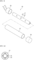
- FIG 3 is an exploded perspective view showing a light source part 20 according to an exemplary embodiment of the present disclosure.
- the light source part 20 includes the light source unit 21 including the substrate 23 and the light source 25 and may include a protective pipe 27 protecting the light source unit 21.
- the substrate 23 is provided to extend in a predetermined direction, for example, one direction.
- the light sources 25, for example, three light sources 25, are arranged on the substrate 23 along the predetermined direction, for example, the one direction.
- the light sources 25 may emit lights having substantially the same wavelength band or light having different wavelength bands from each other. For example, in the exemplary embodiment, all the light sources 25 may emit the lights in the same or similar wavelength. In another exemplary embodiment, some light sources 25 may emit lights having a portion of the ultraviolet light wavelength band, and the other light sources 25 may emit lights having the other portion of the ultraviolet light wavelength band.
- the light sources 25 may be arranged in various ways. For example, a light source emitting a light having a first wavelength band and a light source emitting a light having a second wavelength band different from the first wavelength band may be alternately arranged with each other.
- the protective pipe 27 may protect the substrate 23 and the light sources 25.
- the protective pipe 27 may include a transparent insulating material, may protect the light sources 25 and the substrate 23, and may transmit the lights emitted from the light sources 25.
- the protective pipe 27 may be provided in various materials as long as the above functions are satisfied, and the material should not be limited thereto.
- the protective pipe 27 may include a quartz or a polymer organic material.
- the polymer organic material may be selected by taking into account the wavelengthsof the lights emitted from the light sources 25 since the wavelengths of the lights absorbed or transmitted by the polymer organic material vary depending on a type of monomer, a molding method, and conditions.
- organic polymers such as poly(methylmethacrylate) (PMMA), polyvinylalcohol (PVA), polypropylene (PP), low-density polyethylene (PE), etc.
- PMMA poly(methylmethacrylate)
- PVA polyvinylalcohol
- PP polypropylene
- PE low-density polyethylene
- the protective pipe 27 may have a long cylindrical shape along the extension direction of the substrate 23 and may be provided in a structure in which one side is opened and the other side is blocked.
- a base 29 may be disposed at the opened side to withdraw a wiring 26 to the outside.
- the base 29 may be used as a mounting member that allows the light source unit 21 to be stably placed in the protective pipe 27, and the power wiring 26 may be connected to an outer portion of the base 29 and may be connected to the substrate 23 to supply a power to the light sources 25.
- a photocatalyst layer including a photocatalytic material may be disposed on an inner circumferential surface and/or an outer circumferential surface of the protective pipe 27.
- the photocatalytic material is a material that causes a catalytic reaction by a light irradiated from the light source unit 21 and includes titanium oxide (TiO2), zinc oxide (ZnO), tin oxide (SnO2), or the like.
- the photocatalyst may react to lights of various wavelength bands depending on the material therefor.
- materials that cause a photocatalytic reaction to the light in the ultraviolet light wavelength band among the lights in various wavelength bands may be used.
- the type of the photocatalyst should not be limited thereto or thereby, and another photocatalyst having the same or similar mechanism may be used depending on the light emitted from the light source unit 21.
- the photocatalyst may be activated by the ultraviolet light to cause a chemical reaction, and thus, the photocatalyst decomposes various pollutants or bacteria in the air in contact with the photocatalyst through a redox reaction.
- the air may be sterilized, purified, and deodorized by using the photocatalytic reaction.
- the sterilization may be a bactericidal or antimicrobial activity that destroys enzymes existing in bacteria cells and enzymes acting on a respiratory system, and thus, the growth of bacteria and fungi may be prevented and the toxins from the bacteria and fungi may also be broken down.
- An area where the photocatalyst layer is disposed should not be particularly limited as long as the light emitted from the light source unit 21 may reach the area, and the photocatalyst layer may be disposed on the entire area or some areas of the inner circumferential surface and/or the outer circumferential surface of the protective pipe 27.
- the photocatalyst layer may be disposed not only on the inner circumferential surface or the outer circumferential surface of the light source unit 21 but also on other areas to which the light reaches.
- the photocatalyst layer may be disposed on the pipe 10, in detail, on the inner circumferential surface of the main body 13 of the pipe 10.
- the shape of the protective pipe 27 should not be limited thereto or thereby and may have another shape.
- the protective pipe 27 may have a shape of which both sides are opened, and in this case, the base 29 may be disposed at the both sides of the protective pipe 27.
- the power wiring 26 may be provided through at least one base of the bases 29 at both sides to supply the power to the light sources 25.
- the light source part 20 may provide the light in one direction. As shown in figures, when the light sources 25 are disposed on one surface of the substrate 23, the light travels mainly in a direction substantially perpendicular to the surface on which the light sources 25 are disposed. However, the direction in which the light emitted from the light source part 20 travels may be changed in various ways.
- FIGS. 4A and 4B are sectional views showing light source parts 20 according to an exemplary embodiment of the present disclosure.
- a light source part 20 includes at least one substrate 23 and a plurality of light sources 25 mounted on the substrate 23.
- the substrate 23 of a light source unit 21 may have a variety of shapes in cross-section to emit a light in various directions, e.g., as radially as possible.
- FIG 3 shows the substrate 23 having the triangular shape in cross-section, however, the shape of the substrate 23 should not be limited to the triangular shape.
- the substrate 23 may have a square pillar shape and a pentagonal pillar shape.
- the shape of the substrate 23 is provided as a regular n-polygon (n is a natural number of 3 or more).
- the light sources 25 are arranged on side surfaces of a triangular pillar, a square pillar, and a pentagonal pillar, and the light may exit from each side surface. As a result, the light may travel in various directions rather than one direction.
- the substrate 23 may be provided as one substrate 23 having a triangular pillar shape or the square pillar shape, but it should not be limited thereto or thereby.
- the triangular pillar-shaped, the square pillar-shaped, or the pentagonal pillar-shaped light source part 20 may be formed by assembling a plurality of light source units 21 having a flat plate shape into the triangular pillar, the square pillar, the pentagonal pillar, and the like.
- the light source unit 21 having the triangular shape, or the quadrangular shape in cross-section is shown, however, the light source unit 21 may have the polygonal shape according to embodiments.
- the fluid treatment device having the above-described structure may efficiently treata large amount of the fluid in a short time, which will be described below with reference to the accompanying drawings.
- FIG 5 is a cross-sectional view showing a fluid treatment device according to an exemplary embodiment of the present disclosure
- FIG 6 is a longitudinal-sectional view showing a fluid treatment device according to an exemplary embodiment of the present disclosure.
- FIG 6 shows only the substrate 23, light sources 25, and the main body 13 of the pipe 10.
- the cross-sectional view indicates a cross-section substantially perpendicular to a longitudinal direction of the pipe 10
- the longitudinal-sectional view indicates a cross-section taken along the longitudinal direction of the pipe 10.
- the pipe 10 may have the cylindrical shape with a predetermined thickness and may include the inner circumferential surface and the outer circumferential surface.
- the protective pipe 27 of the light source part 20 may also have the cylindrical shape and may include the inner circumferential surface and the outer circumferential surface.
- the cross-sectional view of the pipe 10 and the protective pipe 27 are provided in the circular shape.
- the substrate 23 having the triangular pillar shape and the light source 25 may be disposed in the protective pipe 27.
- the fluid may be filled between the outer circumferential surface of the protective pipe 27 and the inner circumferential surface of the pipe 10 and may move to the outlet 15 from the inlet 11 along the extension direction of the pipe 10.
- centers of the triangular pillar-shaped substrate 23, the protective pipe 27, and the pipe 10 may be at the same position O when viewed in the cross-sectional view.
- the center of the light source part 20 coincides with the center of the pipe 10 on the cross-sectional view, a distance R from the center O to the inner circumferential surface is constant at any position, and a distance from the light sources 25 to the inner circumferential surface of the pipe 10 is the uniform, and as a result, the light may be applied relatively uniformly to the fluid.
- the fluid may be discharged to the outside after sequentially passing through the inlet 11, the main body 13, and the outlet 15.
- the inlet 11, the main body 13, and the outlet 15 may be sequentially arranged to facilitate the movement of the fluid.
- the inlet 11, the main body 13, and the outlet 15 may be sequentially arranged as shown in FIG 1 , and in this case, the inlet 11 may be disposed at one side of the main body 13, and the outlet 15 may be disposed at the other side of the main body 13.
- the direction of the movement of the fluid partially varies within the body 13, the fluid generally moves along the extension direction D1 of the pipe 10.
- the light source part 20 may include a fluid treatment area in which the fluid is substantially treated.
- the fluid treatment area may be an area in which the light emitted by the light source part 20 reaches the fluid sufficiently so that a desired treatment is performed on the fluid, and the fluid treatment area may include an area between two light sources 25 adjacent to each other and a portion of an outer area of the light sources 25 disposed at outermost positions.
- the fluid treatment area may include an area ((m-1)d) between a first light source 25to a last light source 25, an area corresponding to about 1/4d as the outer area of the first light source 25, and an area corresponding to about 1/4d as the outer area of the last light source 25.
- the outer areas of the first light source 25 and the last light source 25 may be set differently depending on an amount of the light from the light source 25.
- the distance between the light sources 25 and the distance from the light sources 25 to the inner circumferential surface of the pipe 10 may correspond to a predetermined range.
- the first distance D1 may be set in consideration of the orientation angle ( ⁇ ) and the light amount of each light source 25.
- the first distance D1 may be set differently depending on the type of the light source 25 within a range from about 15mm to about 30mm.
- each light source 25 it is preferable for each light source 25 to have the orientation angle ⁇ close to about 180 degrees, and in an exemplary embodiment of the present disclosure, the orientation angle ⁇ of each light source 25 may be about 110 degrees or more. According to another exemplary embodiment of the present disclosure, the orientation angle ⁇ of each light source 25 may be within a range from about 110 degrees to about 150 degrees.
- the orientation angle ⁇ may be an angle at which an amount of the light emitted from each light source 25 corresponds to about 50% of a maximum amount of the light emitted from each light source 25 and may mean an angle obtained by summing angles of both sides based on a line perpendicular to the center of each light source 25.
- the first distance D1 is set within a range in which the amount of light at an intermediate point between the two light sources 25 adjacent to each other has about 70% or more of the amount of light at a vertical point of each light source 25. According to the invention, the first distance D1 may be set within a range in which the amount of light at an intermediate point between the two light sources 25 adjacent to each other has about 80% or more of the amount of light at a vertical point of each light source 25.
- a point perpendicular to the light source 25 positioned at a center of the light sources 25 is referred to as a first point R1
- a point perpendicular to the light source 25 adjacent to one side is referred to as a third point R3
- an intermediate point between the two light sources 25 is referred to as a second point R2
- the first distance D1 is set such that the amount of light at the second point R2 is equal to or greater than about 70% or about 80% of the amount of light at the first point R1 and the third point R3.
- the treatment effect of the fluid may be deteriorated when the fluid passes between two adjacent light sources 25.
- the second distance D2 varies depending on the first distance D1, and a ratio of the first distance D1 to the second distance D2 is 1:0.8 to 1:1.25 or less.
- a total cumulative amount of the light emitted from the light source 25 represents a degree to which the fluid flowing in the pipe 10 is fully treated.
- the treatment effect on the fluid close to the inner circumferential surface of the pipe 10 may be significantly reduced since the distance between the light source part 20 and the inner circumferential surface of the pipe 10 is far.
- the ratio of the first distance D1 to the second distance D2 is from 1:0.8 to 1:1.25.
- the ratio ofthe first distance D1 to the second distance D2 is smaller than about 0.8, the distance between the light source part 20 and the inner circumferential surface of the pipe 10 is short. Therefore, the amount of the fluid flowing between the light source part 20 and the inner circumferential surface of the pipe 10 may decrease, and it may be difficult to treat a sufficient amount of the fluid depending on situations.
- the light source 25 may be provided in a size smaller than that of the substrate 23, but in the drawings of the present disclosure, the size is exaggerated for convenience of description.
- a distance from an upper surface of the substrate 23 to the inner circumferential surface of the pipe 10 is shown to be longer than the distance from the light source 25 to the inner circumferential surface of the pipe 10, however, since a height of the light source 25 is smaller than shown and a difference in actual distances is very small, it is possible to assume that the distance from the upper surface of the substrate 23 to the inner circumferential surface of the pipe 10 is the distance from the light source 25 to the inner circumferential surface of the pipe 10.
- the pipe 10 When viewed in the cross-sectional view, the pipe 10 may have a minimum radius at a point where a ratio of an amount of light in a normal line direction of each light source unit 21 to an amount of light on a line connecting the center of the regular n-polygon to a vertex of the regular n-polygon becomes about 70% or more.
- the substrate 23 when viewed in the cross-sectional view, may have the triangular pillar shape, and three light sources 25 may be provided.
- the size of the pipe 10 is set such that a flow rate does not decrease while maintaining the uniformity of the light emitted from the light source 20, and thus, the fluid in the pipe 10 may be efficiently treated.
- the light emitted from the light source part 20 is the ultraviolet light having the sterilization wavelength and the fluid is water
- the ultraviolet light may be evenly irradiated on the water to effectively sterilize the water, and a capacity of the sterilized water may increase.
- the fluid treatment device according to an exemplary embodiment of the present disclosure should not be limited to the above-described structure, and the structure of the fluid treatment device may be changed in various ways as long as the concept of the present disclosure is maintained.
- FIG 7 is a view showing a fluid treatment device according to another exemplary embodiment of the present disclosure.
- FIG 7 shows a fluid treatment device according to another exemplary embodiment of the present disclosure.
- an inlet 11 and an outlet 15 of the fluid treatment device may be respectively connected to both sides of a main body 13 and may be arranged toward the same direction when viewed in a cross-sectional view.
- the inlet 11 and the outlet 15 may be connected to the main body 13 in a direction perpendicular to a direction in which the main body 13 extends, and the fluid flowing into the main body 13 through the inlet 11 may move along the extension direction of the main body 13 and may be discharged through the outlet 15.
- the movement direction of the fluid may correspond to a ' '-shape.
- the shape of the inlet 11 and the outlet 15 should not be limited thereto or thereby. According to another exemplary embodiment of the present disclosure, the inlet 11 and the outlet 15 may be disposed in different directions from each other when viewed in a cross-sectional view.
- a light source 25 may be provided in various numbers by taking into account a length of the main body 13. For example, four or more light source 25 may be provided.
- FIG 8 is a view showing a fluid treatment device according to another exemplary embodiment of the present disclosure.
- a pipe 10 and a light source part 20 of the fluid treatment device may have different shapes from those of the above-described embodiments.
- the pipe 10 may have a long cylindrical shape along an extension direction and may be provided in a structure in which one side is opened and the other side is blocked.
- a cap 17 may be disposed at the opened side of the pipe 10 to encapsulate a main body 13.
- a through hole through which the light source part 20 is inserted may be defined through the cap 17, and the light source part 20 may be inserted into an internal space 19 of the main body 13 through the through hole.
- a light source unit 21 of the light source part 20 may have a shape corresponding to the shape of the pipe 10.
- a protective pipe 27 may be provided in a structure in which one side is opened and the other side is blocked, and a base 29 may be disposed at the opened side.
- a wiring 26 from a light source 25 may be connected to the outside via the base 29.
- an arrangement of each component may be partially changed as long as a ratio of a distance between two light sources 25 adjacent to each other to a distance between each light source 25 and an inner circumferential surface of the pipe 10 facing the light source 25 may be within the above-mentioned range and the fluid may be treated.
- FIGS. 9 and 10 are sectional views showing an arrangementof a light source unit 21 and a pipe 10 of fluid treatment devices according to an example not forming part of the invention.
- FIGS. 9 and 10 show only a substrate 23 and a light source 25 of the light source unit 21 and a main body 13 of the pipe 10.
- the light source unit 21 may be disposed outside the pipe 10 rather than being disposed in an internal space 19 of the pipe 10.
- the pipe 10 may include a transparent material through which a light emitted from the light source unit 21 transmits, and a target substance to be treated may be filled in the pipe 10 and may move therein.
- the light emitted from the light source unit 21 may be provided to the internal space 19 of the pipe 10 and may treat the fluid filled in the internal space 19 of the pipe 10.
- a ratio of a first distance D1 between two light sources 25 adjacent to each other to a second distance D2 between each light source 25 and an inner circumferential surface of the pipe 10 may be from 1:0.8 to 1: 1.25 when viewed in a longitudinal-sectional view, and in this case, a large amount of the fluid in the pipe 10 may be sterilized as efficiently and uniformly as possible.
- the light source unit may be disposed outside the pipe 10 rather than being disposed in an internal space 19 of the pipe 10 similar to FIG 9 .
- the light source unit may be disposed at both sides (upper and lower portions in FIG 10 ) of the pipe 10.
- the pipe 10 may include a transparent material through which a light emitted from the light source unit transmits, and a target substance to be treated may be filled in the pipe 10 and may move therein.
- the light emitted from the light source unit may be provided to the internal space 19 of the pipe 10 and may treat the fluid filled in the internal space 19 of the pipe 10.
- the light source unit when the light source unit includes a first light source unit 21a disposed at a lower side and including a first substrate 23a and a first light source 25a and a secondlight source unit 21b disposed at an upper side and including a second substrate 23b and a second light source 25b, the light source unit may be disposed on both the upper side and the lower side of the pipe 10, and thus, a sufficient amount of light may reach a center of the pipe 10.
- a ratio of a first distance D1 between two first light sources 25a adjacent to each other in a longitudinal direction to a second distance D2a between each first light source 25a and the center of the pipe 10 facing the first light source 25a may be 1:0.8 to 1: 1.25.
- a ratio of a first distance D1 between two second light sources 25b adjacent to each other in the longitudinal direction to a second distance D2b between each second light source 25b and the center of the pipe 10 facing the second light source 25b may be 1:0.8 to 1: 1.25.
- a third distance D3 may indicate a distance between the first light source 25a and the second light source 25b, which face each other with the pipe 10 interposed therebetween, and may correspond to a sum of the second distance D2a between each first light source 25a and the center of the pipe 10 facing the first light source 25a and the second distance D2b between each second light source 25b and the center of the pipe 10 facing the second light source 25b.
- a diameter of the pipe 10 may be determined by taking into account the third distance D3. That is, a ratio of the first distance D1 between the two adjacent first light sources 25a or between the two adjacent second light sources 25b to the third distance D3 may be from 1: 1.6 to 1:2.5.
- Table 1 shows results of measuring the illuminance ( ⁇ W/cm 2 ) according to a light emission direction and a distance when the fluid treatment device according to the exemplary embodiment of the present disclosure is viewed in cross-section.
- FIG 11 shows the light emission direction when viewed in cross-section and shows six directions measured in Table 1.
- the distance in Table 1 corresponds to a distance between each light source and the inner circumferential surface of the main body of the pipe in the vertical direction.
- the illuminance of the light emitted from each light source in the vertical direction is indicated by 1, 3, and 5, and the illuminance of the light traveling between the light source and the light source is indicated by 2, 4, and 6.
- An optical power meter used in the present exemplary embodiment is 1918-R from Newport Corporation.
- the orientation angle of the light source used in the present exemplary embodiment is about 124 degrees.
- AVG denotes an average of illuminance
- MIN-MAX denotes a ratio of maximum to minimum values of the illuminance according to each distance.
- the optical power meter used in the present exemplary embodiment and the orientation angle of the light source are the same in the following embodiments, and the terminologies are also used in the same sense in the following embodiments.
- Table 2 shows results of measuring the illuminance according to a distance on the longitudinal-section when light emission directions are different from each other in the fluid treatment device according to the exemplary embodiment of the present disclosure.
- “direction” means the light emission directions 1 and 2 shown in FIG 11 .
- a “distance 1” in Table 2 means a distance to the outside from the light source disposed in the middle when three light sources are used and the distance between adjacent light sources is about 25 mm. That is, the distance 1 in Table 2, referring to FIG 6 , means a distance in a direction from a first point toward a third point when the first point R1 is set to zero.
- a “distance 2" is a distance outward from each light source.
- the fluid treatment device when viewed in longitudinal-section, the fluid treatment device according to an exemplary embodiment of the present disclosure exhibited an appropriate amount of the light when the distance 1 was about 0mm, about 20mm, or about 30mm.
- the ratio of the maximum value to the minimum value of illuminance at the distance from 0mm to 30mm including the area where the light source was disposed was much higher than the ratio of the maximum value to the minimum value of illuminance at the distance from 0mm to 50mm including the area where the light source was not disposed. Since the illuminance was significantly reduced at 40 mm and 50 mm points corresponding to the distance 1 where the light source was not provided, it was observed that from about 0mm to about 30mm points correspond to the fluid treatment area.
- the ratio of the maximum value to the minimum value of illuminance was more than about 75% in both 1 direction and 2 direction.
- Table 2 when the distance 2 was equal to or greater than about 20mm, the uniformity of the light was high. In the case of the light emitted in the 1 direction and the 2 direction when viewed in cross-section, the uniformity of the light was very low when the distance 2 was about 10 mm. However, when the distance 2 was about 20mm, the uniformity of the light was relatively high.
- Table 3 shows the results of measuring the time taken for sterilization of about 99.9% according to the distance from the light source based on one light source (3mW, 30mA). Table 3 Distance from light source Time 30mm 100 seconds 50mm 5minutes 100mm 20minutes
- the sterilizing power was decreased rapidly as the distance from the light source was increased based on a single light source.
- the fluid to be sterilized is the flowing water, it is necessary to irradiate uniform light at the same time in the treatment area in which the flowing water is provided since an irradiation time becomes shorter.
- Table 4 shows the illuminance when the light source unit of the light source part has triangular, square, and pentagonal shapes.
- directions 1 and 2 in the triangular shape correspond to the directions 1 and 2 described above
- directions 3 and 4 of the square shape indicate a direction perpendicular to the light source and a direction between two adjacent light sources, similar to the directions 1 and 2, respectively.
- Directions 5 and 6 of the pentagonal shape indicate the direction perpendicular to the light source and the direction between two adjacent light sources, similar to the directions 1 and 2, respectively.
- the distance in Table 4 is the distance from each light source to the inner circumferential surface of the main body of the pipe.
- the uniformity of the light was low.
- the uniformity of the light was very high even when the distance from each light source to the inner circumferential surface of the main body of the pipe was 10 mm. Accordingly, it was observed that the light uniformity is improved even though the distance from each light source to the inner circumferential surface of the main body of the pipe is small when four or more light sources are used in cross-section.
- Table 5 shows the result of measuring the illuminance according to the distance on the longitudinal-section.
- a distance 2 is a distance outward from each light source.
- a distance 1 means a distance outward from the light source disposed in the middle when three light sources are used and a distance between adjacent light sources is 20m.
- a cumulative amount in Table 5 below represents a sum of amounts of lights when the distance 1 is from 0mm to 40mm and the cumulative amount is measured according to the distance 2.
- a cumulative ratio in Table 5 shows a ratio of the cumulative amount according to the distance 2 under the assumption that the cumulative amount of the light is 100% when the distance 2 is 10mm.
- the illuminance was significantly reduced at a point of 30 mm or more corresponding to the distance 1 where the light source was not provided, and thus, in the present exemplary embodiment, it was observed that an area from about 0mm to about 25 mm corresponds to the fluid treatment area.
- the ratio of a maximum value to a minimum value of the illuminance was about 59% when the distance 2 was 15mm, and the ratio of the maximum value to the minimum value of the illuminance was about 82% when the distance 2 was 20mm.
- the ratio of the maximum value to the minimum value of the illuminance was about 91%, and the uniformity of the amount of the light according to the area was very high, but the overall amount of the light was decreased.
- Table 6 shows the result of measuring the illuminance according to the distance on the longitudinal-section.
- a distance 2 is a distance outward from each light source.
- a distance 1 means a distance outward from the light source disposed in the middle when three light sources are used and a distance between adjacent light sources is 25m.
- a cumulative amount in Table 6 below represents a sum of amounts of lights when the distance 1 is from 0mm to 40mm and the cumulative amount is measured according to the distance 2.
- a cumulative ratio in Table 6 shows a ratio of the cumulative amount according to the distance 2 under the assumption that the cumulative amount of the light is 100% when the Table 6 Distanc e1 0 mm 5 mm 10 mm 15 mm 20 mm 25 mm 30 mm 35 mm 40 mm 0 ⁇ 30m m MIN-MAX Accum ulative amoun t Accum ulative ratio Distanc e2 10 mm 775 618 134 105 570 763 663 179 27 14% 3576 100% 15 mm 501 420 186 177 380 495 455 208 65 35% 2822 79% 20 mm 370 320 290 285 350 339 279 175 33 75% 2428 68% 25 mm 284 254 230 240 268 274 252 165 85 81% 1990 56% 30 mm 246 233 220 221 229 231 222 158 49 89% 1779 50% 35 mm 195 189 177 177 193 190 173 126 79 91% 1420
- the illuminance was significantly reduced at a point of 35 mm or more corresponding to the distance 1 where the light source was not provided, and thus, in the present exemplary embodiment, it was observed that an area from about 0mm to about 30 mm corresponds to the fluid treatment area.
- the ratio of a maximum value to a minimum value of the illuminance was about 35% when the distance 2 was 15mm, and the ratio of the maximum value to the minimum value of the illuminance was about 75% when the distance 2 was 20mm.
- the ratio of the maximum value to the minimum value of the illuminance was about 91%, and the uniformity of the light amount according to the area was very high, but the overall amount of the light was decreased.
Landscapes
- Health & Medical Sciences (AREA)
- Life Sciences & Earth Sciences (AREA)
- Organic Chemistry (AREA)
- Hydrology & Water Resources (AREA)
- Engineering & Computer Science (AREA)
- Environmental & Geological Engineering (AREA)
- Water Supply & Treatment (AREA)
- Chemical & Material Sciences (AREA)
- Toxicology (AREA)
- Epidemiology (AREA)
- Animal Behavior & Ethology (AREA)
- General Health & Medical Sciences (AREA)
- Public Health (AREA)
- Veterinary Medicine (AREA)
- Physical Water Treatments (AREA)
- Apparatus For Disinfection Or Sterilisation (AREA)
Claims (10)
- Behandlungsvorrichtung zum Sterilisieren, Reinigen und/oder Desodorieren eines Fluids, umfassend:ein Rohr (10) umfassend einen Einlass (11) und einen Auslass (15) und umfassend einen Innenraum (19), durch den sich ein Fluid bewegt; undeinen Lichtquellenteil (20), der in dem Innenraum (19) angeordnet ist und ein Licht im ultravioletten Wellenlängenband an das Fluid gibt, wobei der Lichtquellenteil (20) mindestens eine Lichtquelleneinheit (21) umfasst, die ein Substrat (23) umfasst, das sich entlang einer vorbestimmten Richtung erstreckt, und eine Vielzahl von Lichtquellen (25), die auf dem Substrat (23) entlang der vorbestimmten Richtung angeordnet sind, wobei die Lichtquellen (25) Leuchtdioden (25) sind und das Licht emittieren, wobei das Zentrum des Lichtquellenteils (20) mit dem Zentrum des Rohrs (10) in der Querschnittsansicht zusammenfällt, wodurch ein Abstand von dem Zentrum zu der inneren Umfangsfläche an jeder Position konstant ist undwobei eine Anzahl der Lichtquelleneinheiten (21) n ist, wobei n drei oder mehr ist, und die Substrate (23) der Lichtquelleneinheiten (21) im Querschnitt betrachtet jeder Seite eines regelmäßigen n-Polygons entsprechen;wobei ein Verhältnis eines ersten Abstands (D1) zwischen zwei einander benachbarten Lichtquellen (25) zu einem zweiten Abstand (D2) von jeder Lichtquelle (25) zu einer inneren Umfangsfläche des Rohrs (10) im Bereich von 1:0,8 bis 1: 1,25 liegt, wenn man es im Längsschnitt betrachtet,wobei der erste Abstand (D1) so eingestellt ist, dass eine Lichtmenge an einem Punkt (R2), der ein Zwischenpunkt zwischen einem ersten Punkt (R1) auf der Innenfläche des Rohrs (10) senkrecht zu einer ersten Lichtquelle (25) und einem dritten Punkt (R3) auf der Innenfläche des Rohrs (10) senkrecht zu einer zweiten Lichtquelle (25) benachbart zu der Seite der ersten Lichtquelle (25) ist, gleich oder größer als etwa 70 %, vorzugsweise gleich oder größer als 80 %, der Lichtmenge am ersten Punkt (R1) und dritten Punkt (R3) ist.
- Behandlungsvorrichtung nach Anspruch 1, wobei der minimale Radius des Rohrs (10) etwa 10 mm übersteigt.
- Behandlungsvorrichtung nach Anspruch 1, wobei jede der Lichtquelleneinheiten drei Lichtquellen (25) umfasst.
- Behandlungsvorrichtung nach Anspruch 2, wobei der erste Abstand in einem Bereich von etwa 15 mm bis etwa 30 mm liegt.
- Behandlungsvorrichtung nach Anspruch 2, wobei die Lichtquelleneinheit (21) außerdem ein transparentes Schutzrohr (27) umfasst, das das Substrat und die Lichtquelle aufnimmt.
- Behandlungsvorrichtung nach Anspruch 5, wobei die Lichtquelleneinheit (21) außerdem eine Basis umfasst, die beide Seiten des transparenten Schutzrohrs (27) umschließt.
- Behandlungsvorrichtung nach Anspruch 2, wobei die Lichtquelle (25) einen Ausrichtungswinkel von 110 Grad bis 150 Grad aufweist.
- Behandlungsvorrichtung nach Anspruch 1, wobei der Einlass (11) und der Auslass (15) im Wesentlichen parallel zu einer Längsrichtung des Rohrs (10) angeordnet sind.
- Behandlungsvorrichtung nach Anspruch 1, wobei mindestens einer aus Einlass (11) und Auslass (15) in einer Richtung angeordnet ist, die zu einer Längsrichtung des Rohrs (10) geneigt oder senkrecht dazu ist.
- Behandlungsvorrichtung nach Anspruch 1, wobei der Lichtquellenteil (20) das Licht in einem Sterilisationswellenlängenband emittiert.
Applications Claiming Priority (2)
| Application Number | Priority Date | Filing Date | Title |
|---|---|---|---|
| KR1020170110576A KR102478463B1 (ko) | 2017-08-31 | 2017-08-31 | 유체 처리 장치 |
| PCT/KR2018/010064 WO2019045487A1 (ko) | 2017-08-31 | 2018-08-30 | 유체 처리 장치 |
Publications (4)
| Publication Number | Publication Date |
|---|---|
| EP3677551A1 EP3677551A1 (de) | 2020-07-08 |
| EP3677551A4 EP3677551A4 (de) | 2021-08-04 |
| EP3677551B1 true EP3677551B1 (de) | 2024-08-14 |
| EP3677551C0 EP3677551C0 (de) | 2024-08-14 |
Family
ID=65527567
Family Applications (1)
| Application Number | Title | Priority Date | Filing Date |
|---|---|---|---|
| EP18851566.2A Active EP3677551B1 (de) | 2017-08-31 | 2018-08-30 | Fluidverarbeitungsvorrichtung |
Country Status (5)
| Country | Link |
|---|---|
| US (2) | US11242266B2 (de) |
| EP (1) | EP3677551B1 (de) |
| KR (1) | KR102478463B1 (de) |
| CN (1) | CN110869322B (de) |
| WO (1) | WO2019045487A1 (de) |
Families Citing this family (4)
| Publication number | Priority date | Publication date | Assignee | Title |
|---|---|---|---|---|
| KR102229197B1 (ko) | 2020-02-12 | 2021-03-17 | 동신대학교산학협력단 | 자외선 led 및 오존 시스템을 적용한 복합 살균장치 |
| CN113277595A (zh) * | 2020-02-20 | 2021-08-20 | 正扬科技有限公司 | 紫外光消毒管道 |
| KR20220034456A (ko) * | 2020-09-11 | 2022-03-18 | 주식회사 싸이큐어 | 표면 및 공간 led 살균 조명장치 |
| JP2022133207A (ja) * | 2021-03-01 | 2022-09-13 | 豊田合成株式会社 | 流体殺菌装置および直管型光源 |
Family Cites Families (23)
| Publication number | Priority date | Publication date | Assignee | Title |
|---|---|---|---|---|
| CN1803643A (zh) * | 2005-01-10 | 2006-07-19 | 俞坚 | 一种环型紫外灯管净水器 |
| GB0606604D0 (en) * | 2006-04-01 | 2006-05-10 | P W Circuts Ltd | Treatment apparatus |
| KR101353582B1 (ko) * | 2007-05-11 | 2014-01-22 | 서울반도체 주식회사 | 자외선 발광 다이오드를 이용한 유체 정화 장치 |
| CN101215017A (zh) * | 2007-12-28 | 2008-07-09 | 李朝林 | 紫外消毒方法 |
| KR20090081660A (ko) * | 2008-01-24 | 2009-07-29 | 웅진코웨이주식회사 | 음용수 유로용 살균장치 |
| KR20090124681A (ko) * | 2008-05-30 | 2009-12-03 | 김찬호 | 살균장치 |
| CN202038892U (zh) * | 2011-02-25 | 2011-11-16 | 中国船舶重工集团公司第七〇四研究所 | 拐点式紫外照射海洋微生物灭活装置 |
| JP5414721B2 (ja) * | 2011-03-17 | 2014-02-12 | 株式会社東芝 | 紫外線照射装置の監視制御システム |
| KR20130106993A (ko) * | 2012-03-21 | 2013-10-01 | 서울바이오시스 주식회사 | 자외선 led를 이용한 휴대용 정수 시스템 |
| EP2829518A4 (de) * | 2012-03-21 | 2015-09-30 | Seoul Viosys Co Ltd | Wasserreinigungssystem mit ultravioletten leds |
| JP2014076205A (ja) * | 2012-10-11 | 2014-05-01 | Eagle Industry Co Ltd | 殺菌装置 |
| US20140105784A1 (en) * | 2012-10-15 | 2014-04-17 | Sharp Kabushiki Kaisha | Ultraviolet treatment device |
| US9227855B2 (en) * | 2012-11-09 | 2016-01-05 | International Business Machines Corporation | Large-scale electricity-less disinfection of fluent water |
| JP6180178B2 (ja) * | 2013-05-13 | 2017-08-16 | 国立大学法人埼玉大学 | 紫外線照射水処理装置 |
| EP2999669B1 (de) * | 2013-05-22 | 2017-02-08 | Merck Patent GmbH | Vorrichtung zur flüssigkeitsdesinfektion mittels ultravioletter strahlung |
| JP2014233646A (ja) * | 2013-05-30 | 2014-12-15 | 日機装株式会社 | 水浄化装置 |
| CN110422906A (zh) * | 2013-09-05 | 2019-11-08 | 首尔伟傲世有限公司 | 杀菌装置 |
| KR20160035265A (ko) * | 2014-09-23 | 2016-03-31 | 서울바이오시스 주식회사 | Uv led를 이용한 유체 살균 장치 |
| KR101668705B1 (ko) * | 2014-11-11 | 2016-10-28 | 엘지전자 주식회사 | 수처리 장치 |
| KR102533593B1 (ko) * | 2017-04-14 | 2023-05-18 | 서울바이오시스 주식회사 | 살균 모듈, 정수 장치 및 정수 장치를 포함하는 시스템 |
| KR102103973B1 (ko) * | 2018-04-13 | 2020-04-23 | (주)포인트엔지니어링 | 자외선 살균 모듈 |
| JP7262985B2 (ja) * | 2018-12-04 | 2023-04-24 | スタンレー電気株式会社 | 光源モジュール装置、流体殺菌装置 |
| US11825828B2 (en) * | 2018-12-21 | 2023-11-28 | Deloren E. Anderson | System and method for treating underwater invasive species |
-
2017
- 2017-08-31 KR KR1020170110576A patent/KR102478463B1/ko active Active
-
2018
- 2018-08-30 EP EP18851566.2A patent/EP3677551B1/de active Active
- 2018-08-30 WO PCT/KR2018/010064 patent/WO2019045487A1/ko not_active Ceased
- 2018-08-30 CN CN201880042488.0A patent/CN110869322B/zh not_active Expired - Fee Related
-
2020
- 2020-02-28 US US16/805,389 patent/US11242266B2/en active Active
-
2021
- 2021-07-26 US US17/385,364 patent/US11572290B2/en active Active
Also Published As
| Publication number | Publication date |
|---|---|
| US20210347657A1 (en) | 2021-11-11 |
| EP3677551C0 (de) | 2024-08-14 |
| EP3677551A1 (de) | 2020-07-08 |
| US20200239334A1 (en) | 2020-07-30 |
| KR20190024037A (ko) | 2019-03-08 |
| CN110869322A (zh) | 2020-03-06 |
| WO2019045487A1 (ko) | 2019-03-07 |
| EP3677551A4 (de) | 2021-08-04 |
| CN110869322B (zh) | 2023-02-21 |
| US11242266B2 (en) | 2022-02-08 |
| KR102478463B1 (ko) | 2022-12-20 |
| US11572290B2 (en) | 2023-02-07 |
Similar Documents
| Publication | Publication Date | Title |
|---|---|---|
| US11572290B2 (en) | Fluid treatment apparatus | |
| US9381458B2 (en) | Device for disinfecting gases and/or liquids | |
| US12398051B2 (en) | Fluid treatment module | |
| US9017613B2 (en) | Ultraviolet photoreactor for the purification of fluids | |
| US11939240B2 (en) | Sterilizing device | |
| TW201604140A (zh) | 用於流體處理之方法、系統及裝置 | |
| PL245611B1 (pl) | Urządzenie do uzdatniania płynów | |
| CN112499721A (zh) | 一种具有柱形深紫外消毒辐射源的净水反应器 | |
| EP4147726B1 (de) | Ultraviolettsterilisierungsvorrichtung | |
| KR20180124569A (ko) | 유체 처리 장치 | |
| US20220304342A1 (en) | In-Line Fluid and Filter Sterilization Apparatus | |
| KR100877562B1 (ko) | 비접촉식 자외선 수처리 장치 및 이를 이용한 수처리 방법 | |
| KR102641966B1 (ko) | 유체 처리 장치 | |
| KR102660075B1 (ko) | 유체 처리 장치 | |
| JP7591602B2 (ja) | 紫外線殺菌装置 | |
| KR20180036948A (ko) | 자외선 led를 이용한 휴대용 정수 시스템 | |
| JP2022076596A (ja) | 深紫外線殺菌装置 | |
| KR20260043627A (ko) | 관로 설치형 자외선 살균소독 시스템 | |
| KR20200085601A (ko) | 살균 모듈 및 이를 포함하는 살균 장치 |
Legal Events
| Date | Code | Title | Description |
|---|---|---|---|
| STAA | Information on the status of an ep patent application or granted ep patent |
Free format text: STATUS: THE INTERNATIONAL PUBLICATION HAS BEEN MADE |
|
| PUAI | Public reference made under article 153(3) epc to a published international application that has entered the european phase |
Free format text: ORIGINAL CODE: 0009012 |
|
| STAA | Information on the status of an ep patent application or granted ep patent |
Free format text: STATUS: REQUEST FOR EXAMINATION WAS MADE |
|
| 17P | Request for examination filed |
Effective date: 20200331 |
|
| AK | Designated contracting states |
Kind code of ref document: A1 Designated state(s): AL AT BE BG CH CY CZ DE DK EE ES FI FR GB GR HR HU IE IS IT LI LT LU LV MC MK MT NL NO PL PT RO RS SE SI SK SM TR |
|
| AX | Request for extension of the european patent |
Extension state: BA ME |
|
| DAV | Request for validation of the european patent (deleted) | ||
| DAX | Request for extension of the european patent (deleted) | ||
| A4 | Supplementary search report drawn up and despatched |
Effective date: 20210702 |
|
| RIC1 | Information provided on ipc code assigned before grant |
Ipc: C02F 1/32 20060101AFI20210628BHEP Ipc: A61L 9/20 20060101ALI20210628BHEP Ipc: C02F 1/72 20060101ALN20210628BHEP |
|
| STAA | Information on the status of an ep patent application or granted ep patent |
Free format text: STATUS: EXAMINATION IS IN PROGRESS |
|
| 17Q | First examination report despatched |
Effective date: 20220323 |
|
| GRAP | Despatch of communication of intention to grant a patent |
Free format text: ORIGINAL CODE: EPIDOSNIGR1 |
|
| STAA | Information on the status of an ep patent application or granted ep patent |
Free format text: STATUS: GRANT OF PATENT IS INTENDED |
|
| RIC1 | Information provided on ipc code assigned before grant |
Ipc: C02F 1/72 20060101ALN20240213BHEP Ipc: A61L 9/20 20060101ALI20240213BHEP Ipc: C02F 1/32 20060101AFI20240213BHEP |
|
| RIC1 | Information provided on ipc code assigned before grant |
Ipc: C02F 1/72 20060101ALN20240222BHEP Ipc: A61L 9/20 20060101ALI20240222BHEP Ipc: C02F 1/32 20060101AFI20240222BHEP |
|
| INTG | Intention to grant announced |
Effective date: 20240305 |
|
| GRAS | Grant fee paid |
Free format text: ORIGINAL CODE: EPIDOSNIGR3 |
|
| GRAA | (expected) grant |
Free format text: ORIGINAL CODE: 0009210 |
|
| STAA | Information on the status of an ep patent application or granted ep patent |
Free format text: STATUS: THE PATENT HAS BEEN GRANTED |
|
| AK | Designated contracting states |
Kind code of ref document: B1 Designated state(s): AL AT BE BG CH CY CZ DE DK EE ES FI FR GB GR HR HU IE IS IT LI LT LU LV MC MK MT NL NO PL PT RO RS SE SI SK SM TR |
|
| REG | Reference to a national code |
Ref country code: GB Ref legal event code: FG4D |
|
| REG | Reference to a national code |
Ref country code: CH Ref legal event code: EP |
|
| REG | Reference to a national code |
Ref country code: DE Ref legal event code: R096 Ref document number: 602018073183 Country of ref document: DE |
|
| REG | Reference to a national code |
Ref country code: IE Ref legal event code: FG4D |
|
| U01 | Request for unitary effect filed |
Effective date: 20240911 |
|
| U07 | Unitary effect registered |
Designated state(s): AT BE BG DE DK EE FI FR IT LT LU LV MT NL PT RO SE SI Effective date: 20240926 |
|
| U20 | Renewal fee for the european patent with unitary effect paid |
Year of fee payment: 7 Effective date: 20240930 |
|
| PG25 | Lapsed in a contracting state [announced via postgrant information from national office to epo] |
Ref country code: NO Free format text: LAPSE BECAUSE OF FAILURE TO SUBMIT A TRANSLATION OF THE DESCRIPTION OR TO PAY THE FEE WITHIN THE PRESCRIBED TIME-LIMIT Effective date: 20241114 |
|
| PG25 | Lapsed in a contracting state [announced via postgrant information from national office to epo] |
Ref country code: PL Free format text: LAPSE BECAUSE OF FAILURE TO SUBMIT A TRANSLATION OF THE DESCRIPTION OR TO PAY THE FEE WITHIN THE PRESCRIBED TIME-LIMIT Effective date: 20240814 Ref country code: GR Free format text: LAPSE BECAUSE OF FAILURE TO SUBMIT A TRANSLATION OF THE DESCRIPTION OR TO PAY THE FEE WITHIN THE PRESCRIBED TIME-LIMIT Effective date: 20241115 |
|
| PG25 | Lapsed in a contracting state [announced via postgrant information from national office to epo] |
Ref country code: IS Free format text: LAPSE BECAUSE OF FAILURE TO SUBMIT A TRANSLATION OF THE DESCRIPTION OR TO PAY THE FEE WITHIN THE PRESCRIBED TIME-LIMIT Effective date: 20241214 |
|
| PG25 | Lapsed in a contracting state [announced via postgrant information from national office to epo] |
Ref country code: HR Free format text: LAPSE BECAUSE OF FAILURE TO SUBMIT A TRANSLATION OF THE DESCRIPTION OR TO PAY THE FEE WITHIN THE PRESCRIBED TIME-LIMIT Effective date: 20240814 |
|
| PG25 | Lapsed in a contracting state [announced via postgrant information from national office to epo] |
Ref country code: ES Free format text: LAPSE BECAUSE OF FAILURE TO SUBMIT A TRANSLATION OF THE DESCRIPTION OR TO PAY THE FEE WITHIN THE PRESCRIBED TIME-LIMIT Effective date: 20240814 Ref country code: RS Free format text: LAPSE BECAUSE OF FAILURE TO SUBMIT A TRANSLATION OF THE DESCRIPTION OR TO PAY THE FEE WITHIN THE PRESCRIBED TIME-LIMIT Effective date: 20241114 |
|
| PG25 | Lapsed in a contracting state [announced via postgrant information from national office to epo] |
Ref country code: RS Free format text: LAPSE BECAUSE OF FAILURE TO SUBMIT A TRANSLATION OF THE DESCRIPTION OR TO PAY THE FEE WITHIN THE PRESCRIBED TIME-LIMIT Effective date: 20241114 Ref country code: PL Free format text: LAPSE BECAUSE OF FAILURE TO SUBMIT A TRANSLATION OF THE DESCRIPTION OR TO PAY THE FEE WITHIN THE PRESCRIBED TIME-LIMIT Effective date: 20240814 Ref country code: NO Free format text: LAPSE BECAUSE OF FAILURE TO SUBMIT A TRANSLATION OF THE DESCRIPTION OR TO PAY THE FEE WITHIN THE PRESCRIBED TIME-LIMIT Effective date: 20241114 Ref country code: IS Free format text: LAPSE BECAUSE OF FAILURE TO SUBMIT A TRANSLATION OF THE DESCRIPTION OR TO PAY THE FEE WITHIN THE PRESCRIBED TIME-LIMIT Effective date: 20241214 Ref country code: HR Free format text: LAPSE BECAUSE OF FAILURE TO SUBMIT A TRANSLATION OF THE DESCRIPTION OR TO PAY THE FEE WITHIN THE PRESCRIBED TIME-LIMIT Effective date: 20240814 Ref country code: GR Free format text: LAPSE BECAUSE OF FAILURE TO SUBMIT A TRANSLATION OF THE DESCRIPTION OR TO PAY THE FEE WITHIN THE PRESCRIBED TIME-LIMIT Effective date: 20241115 Ref country code: ES Free format text: LAPSE BECAUSE OF FAILURE TO SUBMIT A TRANSLATION OF THE DESCRIPTION OR TO PAY THE FEE WITHIN THE PRESCRIBED TIME-LIMIT Effective date: 20240814 |
|
| REG | Reference to a national code |
Ref country code: CH Ref legal event code: PL |
|
| PG25 | Lapsed in a contracting state [announced via postgrant information from national office to epo] |
Ref country code: SM Free format text: LAPSE BECAUSE OF FAILURE TO SUBMIT A TRANSLATION OF THE DESCRIPTION OR TO PAY THE FEE WITHIN THE PRESCRIBED TIME-LIMIT Effective date: 20240814 |
|
| PG25 | Lapsed in a contracting state [announced via postgrant information from national office to epo] |
Ref country code: CH Free format text: LAPSE BECAUSE OF NON-PAYMENT OF DUE FEES Effective date: 20240831 |
|
| PG25 | Lapsed in a contracting state [announced via postgrant information from national office to epo] |
Ref country code: CZ Free format text: LAPSE BECAUSE OF FAILURE TO SUBMIT A TRANSLATION OF THE DESCRIPTION OR TO PAY THE FEE WITHIN THE PRESCRIBED TIME-LIMIT Effective date: 20240814 |
|
| PG25 | Lapsed in a contracting state [announced via postgrant information from national office to epo] |
Ref country code: SK Free format text: LAPSE BECAUSE OF FAILURE TO SUBMIT A TRANSLATION OF THE DESCRIPTION OR TO PAY THE FEE WITHIN THE PRESCRIBED TIME-LIMIT Effective date: 20240814 |
|
| PLBE | No opposition filed within time limit |
Free format text: ORIGINAL CODE: 0009261 |
|
| STAA | Information on the status of an ep patent application or granted ep patent |
Free format text: STATUS: NO OPPOSITION FILED WITHIN TIME LIMIT |
|
| PG25 | Lapsed in a contracting state [announced via postgrant information from national office to epo] |
Ref country code: MC Free format text: LAPSE BECAUSE OF FAILURE TO SUBMIT A TRANSLATION OF THE DESCRIPTION OR TO PAY THE FEE WITHIN THE PRESCRIBED TIME-LIMIT Effective date: 20240814 |
|
| 26N | No opposition filed |
Effective date: 20250515 |
|
| GBPC | Gb: european patent ceased through non-payment of renewal fee |
Effective date: 20241114 |
|
| PG25 | Lapsed in a contracting state [announced via postgrant information from national office to epo] |
Ref country code: IE Free format text: LAPSE BECAUSE OF NON-PAYMENT OF DUE FEES Effective date: 20240830 |
|
| U20 | Renewal fee for the european patent with unitary effect paid |
Year of fee payment: 8 Effective date: 20250822 |
|
| PG25 | Lapsed in a contracting state [announced via postgrant information from national office to epo] |
Ref country code: GB Free format text: LAPSE BECAUSE OF NON-PAYMENT OF DUE FEES Effective date: 20241114 |
|
| PG25 | Lapsed in a contracting state [announced via postgrant information from national office to epo] |
Ref country code: CY Free format text: LAPSE BECAUSE OF FAILURE TO SUBMIT A TRANSLATION OF THE DESCRIPTION OR TO PAY THE FEE WITHIN THE PRESCRIBED TIME-LIMIT; INVALID AB INITIO Effective date: 20180830 |
|
| PG25 | Lapsed in a contracting state [announced via postgrant information from national office to epo] |
Ref country code: HU Free format text: LAPSE BECAUSE OF FAILURE TO SUBMIT A TRANSLATION OF THE DESCRIPTION OR TO PAY THE FEE WITHIN THE PRESCRIBED TIME-LIMIT; INVALID AB INITIO Effective date: 20180830 |