EP3677102B1 - Verfahren und system zum stapeln von bedruckten substraten - Google Patents
Verfahren und system zum stapeln von bedruckten substraten Download PDFInfo
- Publication number
- EP3677102B1 EP3677102B1 EP17934962.6A EP17934962A EP3677102B1 EP 3677102 B1 EP3677102 B1 EP 3677102B1 EP 17934962 A EP17934962 A EP 17934962A EP 3677102 B1 EP3677102 B1 EP 3677102B1
- Authority
- EP
- European Patent Office
- Prior art keywords
- stack
- stacking
- axis
- substrates
- printed substrates
- Prior art date
- Legal status (The legal status is an assumption and is not a legal conclusion. Google has not performed a legal analysis and makes no representation as to the accuracy of the status listed.)
- Active
Links
Images


Classifications
-
- B—PERFORMING OPERATIONS; TRANSPORTING
- B65—CONVEYING; PACKING; STORING; HANDLING THIN OR FILAMENTARY MATERIAL
- B65H—HANDLING THIN OR FILAMENTARY MATERIAL, e.g. SHEETS, WEBS, CABLES
- B65H29/00—Delivering or advancing articles from machines; Advancing articles to or into piles
- B65H29/26—Delivering or advancing articles from machines; Advancing articles to or into piles by dropping the articles
- B65H29/34—Delivering or advancing articles from machines; Advancing articles to or into piles by dropping the articles from supports slid from under the articles
-
- B—PERFORMING OPERATIONS; TRANSPORTING
- B65—CONVEYING; PACKING; STORING; HANDLING THIN OR FILAMENTARY MATERIAL
- B65H—HANDLING THIN OR FILAMENTARY MATERIAL, e.g. SHEETS, WEBS, CABLES
- B65H31/00—Pile receivers
- B65H31/02—Pile receivers with stationary end support against which pile accumulates
-
- B—PERFORMING OPERATIONS; TRANSPORTING
- B65—CONVEYING; PACKING; STORING; HANDLING THIN OR FILAMENTARY MATERIAL
- B65H—HANDLING THIN OR FILAMENTARY MATERIAL, e.g. SHEETS, WEBS, CABLES
- B65H31/00—Pile receivers
- B65H31/04—Pile receivers with movable end support arranged to recede as pile accumulates
- B65H31/08—Pile receivers with movable end support arranged to recede as pile accumulates the articles being piled one above another
- B65H31/10—Pile receivers with movable end support arranged to recede as pile accumulates the articles being piled one above another and applied at the top of the pile
-
- B—PERFORMING OPERATIONS; TRANSPORTING
- B65—CONVEYING; PACKING; STORING; HANDLING THIN OR FILAMENTARY MATERIAL
- B65H—HANDLING THIN OR FILAMENTARY MATERIAL, e.g. SHEETS, WEBS, CABLES
- B65H31/00—Pile receivers
- B65H31/20—Pile receivers adjustable for different article sizes
-
- B—PERFORMING OPERATIONS; TRANSPORTING
- B65—CONVEYING; PACKING; STORING; HANDLING THIN OR FILAMENTARY MATERIAL
- B65H—HANDLING THIN OR FILAMENTARY MATERIAL, e.g. SHEETS, WEBS, CABLES
- B65H31/00—Pile receivers
- B65H31/30—Arrangements for removing completed piles
- B65H31/3009—Arrangements for removing completed piles by dropping, e.g. removing the pile support from under the pile
- B65H31/3018—Arrangements for removing completed piles by dropping, e.g. removing the pile support from under the pile from opposite part-support elements, e.g. operated simultaneously
-
- B—PERFORMING OPERATIONS; TRANSPORTING
- B65—CONVEYING; PACKING; STORING; HANDLING THIN OR FILAMENTARY MATERIAL
- B65H—HANDLING THIN OR FILAMENTARY MATERIAL, e.g. SHEETS, WEBS, CABLES
- B65H31/00—Pile receivers
- B65H31/34—Apparatus for squaring-up piled articles
- B65H31/38—Apparatus for vibrating or knocking the pile during piling
-
- B—PERFORMING OPERATIONS; TRANSPORTING
- B65—CONVEYING; PACKING; STORING; HANDLING THIN OR FILAMENTARY MATERIAL
- B65H—HANDLING THIN OR FILAMENTARY MATERIAL, e.g. SHEETS, WEBS, CABLES
- B65H33/00—Forming counted batches in delivery pile or stream of articles
- B65H33/06—Forming counted batches in delivery pile or stream of articles by displacing articles to define batches
- B65H33/08—Displacing whole batches, e.g. forming stepped piles
-
- B—PERFORMING OPERATIONS; TRANSPORTING
- B65—CONVEYING; PACKING; STORING; HANDLING THIN OR FILAMENTARY MATERIAL
- B65H—HANDLING THIN OR FILAMENTARY MATERIAL, e.g. SHEETS, WEBS, CABLES
- B65H43/00—Use of control, checking, or safety devices, e.g. automatic devices comprising an element for sensing a variable
- B65H43/06—Use of control, checking, or safety devices, e.g. automatic devices comprising an element for sensing a variable detecting, or responding to, completion of pile
-
- B—PERFORMING OPERATIONS; TRANSPORTING
- B65—CONVEYING; PACKING; STORING; HANDLING THIN OR FILAMENTARY MATERIAL
- B65H—HANDLING THIN OR FILAMENTARY MATERIAL, e.g. SHEETS, WEBS, CABLES
- B65H9/00—Registering, e.g. orientating, articles; Devices therefor
- B65H9/10—Pusher and like movable registers; Pusher or gripper devices which move articles into registered position
- B65H9/101—Pusher and like movable registers; Pusher or gripper devices which move articles into registered position acting on the edge of the article
-
- B—PERFORMING OPERATIONS; TRANSPORTING
- B65—CONVEYING; PACKING; STORING; HANDLING THIN OR FILAMENTARY MATERIAL
- B65H—HANDLING THIN OR FILAMENTARY MATERIAL, e.g. SHEETS, WEBS, CABLES
- B65H2301/00—Handling processes for sheets or webs
- B65H2301/40—Type of handling process
- B65H2301/42—Piling, depiling, handling piles
- B65H2301/421—Forming a pile
- B65H2301/4212—Forming a pile of articles substantially horizontal
-
- B—PERFORMING OPERATIONS; TRANSPORTING
- B65—CONVEYING; PACKING; STORING; HANDLING THIN OR FILAMENTARY MATERIAL
- B65H—HANDLING THIN OR FILAMENTARY MATERIAL, e.g. SHEETS, WEBS, CABLES
- B65H2301/00—Handling processes for sheets or webs
- B65H2301/40—Type of handling process
- B65H2301/42—Piling, depiling, handling piles
- B65H2301/421—Forming a pile
- B65H2301/4219—Forming a pile forming a pile in which articles are offset from each other, e.g. forming stepped pile
- B65H2301/42192—Forming a pile forming a pile in which articles are offset from each other, e.g. forming stepped pile forming a pile of articles in zigzag fashion
-
- B—PERFORMING OPERATIONS; TRANSPORTING
- B65—CONVEYING; PACKING; STORING; HANDLING THIN OR FILAMENTARY MATERIAL
- B65H—HANDLING THIN OR FILAMENTARY MATERIAL, e.g. SHEETS, WEBS, CABLES
- B65H2301/00—Handling processes for sheets or webs
- B65H2301/40—Type of handling process
- B65H2301/42—Piling, depiling, handling piles
- B65H2301/421—Forming a pile
- B65H2301/4219—Forming a pile forming a pile in which articles are offset from each other, e.g. forming stepped pile
- B65H2301/42194—Forming a pile forming a pile in which articles are offset from each other, e.g. forming stepped pile forming a pile in which articles are offset from each other in the delivery direction
-
- B—PERFORMING OPERATIONS; TRANSPORTING
- B65—CONVEYING; PACKING; STORING; HANDLING THIN OR FILAMENTARY MATERIAL
- B65H—HANDLING THIN OR FILAMENTARY MATERIAL, e.g. SHEETS, WEBS, CABLES
- B65H2301/00—Handling processes for sheets or webs
- B65H2301/40—Type of handling process
- B65H2301/42—Piling, depiling, handling piles
- B65H2301/422—Handling piles, sets or stacks of articles
- B65H2301/4222—Squaring-up piles
-
- B—PERFORMING OPERATIONS; TRANSPORTING
- B65—CONVEYING; PACKING; STORING; HANDLING THIN OR FILAMENTARY MATERIAL
- B65H—HANDLING THIN OR FILAMENTARY MATERIAL, e.g. SHEETS, WEBS, CABLES
- B65H2301/00—Handling processes for sheets or webs
- B65H2301/40—Type of handling process
- B65H2301/42—Piling, depiling, handling piles
- B65H2301/422—Handling piles, sets or stacks of articles
- B65H2301/4226—Delivering, advancing piles
- B65H2301/42261—Delivering, advancing piles by dropping
-
- B—PERFORMING OPERATIONS; TRANSPORTING
- B65—CONVEYING; PACKING; STORING; HANDLING THIN OR FILAMENTARY MATERIAL
- B65H—HANDLING THIN OR FILAMENTARY MATERIAL, e.g. SHEETS, WEBS, CABLES
- B65H2405/00—Parts for holding the handled material
- B65H2405/10—Cassettes, holders, bins, decks, trays, supports or magazines for sheets stacked substantially horizontally
- B65H2405/11—Parts and details thereof
- B65H2405/114—Side, i.e. portion parallel to the feeding / delivering direction
-
- B—PERFORMING OPERATIONS; TRANSPORTING
- B65—CONVEYING; PACKING; STORING; HANDLING THIN OR FILAMENTARY MATERIAL
- B65H—HANDLING THIN OR FILAMENTARY MATERIAL, e.g. SHEETS, WEBS, CABLES
- B65H2511/00—Dimensions; Position; Numbers; Identification; Occurrences
- B65H2511/10—Size; Dimensions
- B65H2511/15—Height, e.g. of stack
-
- B—PERFORMING OPERATIONS; TRANSPORTING
- B65—CONVEYING; PACKING; STORING; HANDLING THIN OR FILAMENTARY MATERIAL
- B65H—HANDLING THIN OR FILAMENTARY MATERIAL, e.g. SHEETS, WEBS, CABLES
- B65H2511/00—Dimensions; Position; Numbers; Identification; Occurrences
- B65H2511/30—Numbers, e.g. of windings or rotations
-
- B—PERFORMING OPERATIONS; TRANSPORTING
- B65—CONVEYING; PACKING; STORING; HANDLING THIN OR FILAMENTARY MATERIAL
- B65H—HANDLING THIN OR FILAMENTARY MATERIAL, e.g. SHEETS, WEBS, CABLES
- B65H2515/00—Physical entities not provided for in groups B65H2511/00 or B65H2513/00
- B65H2515/10—Mass, e.g. mass flow rate; Weight; Inertia
-
- B—PERFORMING OPERATIONS; TRANSPORTING
- B65—CONVEYING; PACKING; STORING; HANDLING THIN OR FILAMENTARY MATERIAL
- B65H—HANDLING THIN OR FILAMENTARY MATERIAL, e.g. SHEETS, WEBS, CABLES
- B65H2801/00—Application field
- B65H2801/03—Image reproduction devices
- B65H2801/15—Digital printing machines
-
- H—ELECTRICITY
- H05—ELECTRIC TECHNIQUES NOT OTHERWISE PROVIDED FOR
- H05K—PRINTED CIRCUITS; CASINGS OR CONSTRUCTIONAL DETAILS OF ELECTRIC APPARATUS; MANUFACTURE OF ASSEMBLAGES OF ELECTRICAL COMPONENTS
- H05K3/00—Apparatus or processes for manufacturing printed circuits
- H05K3/10—Apparatus or processes for manufacturing printed circuits in which conductive material is applied to the insulating support in such a manner as to form the desired conductive pattern
- H05K3/12—Apparatus or processes for manufacturing printed circuits in which conductive material is applied to the insulating support in such a manner as to form the desired conductive pattern using thick film techniques, e.g. printing techniques to apply the conductive material or similar techniques for applying conductive paste or ink patterns
Definitions
- Printer systems are arranged to print printing fluid, such as ink, on to substrates. Once the substrates have been printed on, the printed substrates may be stacked on top of each other. In an example printer system, the printed substrates are transported on vacuum belts to a location in which they are to be stacked.
- US2009/110458 discloses a post-processing apparatus and an image forming apparatus.
- GB2341598 discloses sheet stacking trays.
- JPH054616A discloses a device for disposing of printed books.
- EP1203740 discloses an apparatus for preparing batches of sheets.
- an example stacking system comprises a stacking member, movable between a first position in which the stacking member is configured to partially support a first stack of printed substrates, and a second position in which the stacking member is disengaged from the first stack.
- the stacking system may further comprise a receptacle positioned below the stacking member that is configured to hold a second stack of printed substrates.
- a controller may be configured to cause the stacking member to move between the first position and the second position when the first stack satisfies a criterion, thereby depositing the first stack into the receptacle on top of the second stack.
- the example stacking system can more precisely position printed substrates in a stack.
- the use of one or more stacking members, and stacking the first stack independently of the second stack, may allow the positioning of the substrates to be accurately controlled.
- a first stacking scheme may specify a stack quality specification.
- the stack quality specification may specify that the maximum offset between substrates in a stack is no greater than a predetermined measurement value, such as about 10mm, about 5mm, or about 3mm for example.
- the stack quality specification may specify that the stack of printed substrates is well-ordered, and each substrate within the stack is well-aligned with the other substrates in the stack.
- the substrates within the first stack can be ordered and aligned before placing onto the second stack.
- This ordering and alignment can be achieved by agitating the substrates within the first stack in one or more directions.
- the substrates can be vibrated back and forth along a first axis to align the substrates along the first axis, and the substrates can be vibrated back and forth along a second, perpendicular axis, to align the substrates along the second axis.
- the first axis may be aligned with a length direction of the substrate, perpendicular to a transport direction.
- the second axis may be aligned with a width direction of the substrate, parallel to the transport direction.
- a second stacking scheme may specify how substrates of different sizes/dimensions are stacked on top of each other.
- a first batch of substrates may be of the same size, whereas a second subsequent batch of substrates may be of a different size to the first batch.
- the second batch may have different length and/or width dimensions to the first batch.
- the second batch may be stacked on top of the first batch in different ways.
- the first and second batches may be aligned along a predetermined edge of the substrates, such as a trailing edge, a leading edge, a left edge and a right edge relative to a transport direction.
- allowing for a second stacking scheme can be achieved by using one or more stacking members.
- the stack By sequentially receiving and stacking a plurality of printed substrates on the stacking member to create a first stack of substrates, the stack can be moved relative to the second stack of substrates below.
- One or more other elements may also be used to aid movement in other spatial dimensions, such as a direction or axis parallel to the transport direction. Alternatively, or additionally, spacing between the stacking members and/or other elements can be adjusted so that substrates of different sizes can be received.
- a third stacking scheme may specify how batches of substrates are distinguished from other batches. For example, batches or print-jobs may be offset or displaced from each other. The offset may be along a length direction of the substrate, perpendicular to a transport direction. Each batch may then be easily identifiable from other batches.
- an offset may be achieved by using one or more stacking members. By sequentially receiving and stacking a plurality of printed substrates on the stacking member to create a first stack of substrates, the stack can be moved relative to the second stack of substrates below. In some examples, the batches may be offset by about 30mm, about 25mm or about 20mm.
- the stacking system may stack substrates that are received at irregular intervals.
- the system may be able to stack substrates in all the ways discussed above. No rigorous calibration process may be needed to ensure that substrates being stacked are well-aligned before deposited on a stack.
- vacuum belt stacking systems involve calibration specific to each job/batch being printed. This process is labour intensive, and is prone to noise which can result in the stack failing to meet the stack quality specification for example.
- FIG. 1 is a schematic diagram showing a printer system 100 in accordance with an example.
- the printing system 100 comprises a printer 102 and a stacking system 104.
- the printing system 100 is configured to deposit printing fluid, such as ink, onto unprinted, or partially printed substrates 106. Once printed upon, the printed substrates 108 may travel along a conveyor belt 110, or any other conveying assembly, towards the stacking system 104 in a transport direction indicated by arrow 118.
- the stacking system 104 is configured to stack the plurality of printed substrates 108.
- the controller 112 may comprise one or more processors for example.
- the controller 112 may further comprise memory, configured to store instructions that when executed, cause the processor(s) to implement one or more methods.
- the controller may control the printer 102, the conveyor assembly 110 and the stacking system 104.
- the memory may be a non-transitory computer-readable storage medium in some examples.
- the controller 112 may be connected directly or indirectly to the various components of the printing system 100 via one or more communication paths 114, 116, shown depicted as dashed lines. In the example of Figure 1 , the controller 112 is communicatively coupled to the printer 102 and the stacking system 104, however, greater or fewer communication paths may also be present. In other examples, the printer 102 and stacking system 104 each have their own controller, which may operate independently of each other.
- Figure 2 depicts a plan, or top-down view of an example stacking system 200 arranged according to a first configuration.
- Figure 4 depicts a side view of the stacking system 200 in the first configuration.
- the stacking system 200 may be part of a printing system 100, for example.
- Figure 2 shows printed substrates 202 being received in the stacking system 200 on a receiving assembly 204.
- the receiving assembly comprises a conveyor belt, such as a vacuum belt, however in other systems the receiving assembly 204 may comprise a roller, a gripper bar, or flipping wheel, for example.
- the receiving assembly 204 is configured to receive the printed substrates 202 and position the substrates 202 within the stacking system 200.
- the receiving assembly 204 causes the substrates 202 to travel in a transport direction indicated by arrow 210.
- the stacking system 200 comprises a first stacking member 206 and a second stacking member 208 upon which a plurality of printed substrates 202 are sequentially received and stacked, to form a first stack 212.
- the stacking members may have a generally flat or planar portion positioned underneath at least an edge region of the substrate and may be arranged either side of the transport direction. In other examples there may be one stacking member, or there may be more than two stacking members.
- the plurality of printed substrates 202 stacked on the stacking members 206, 208 may be partially supported by the stacking members 206, 208.
- the stacking members 206, 208 are positioned to engage with a peripheral or edge region of the substrates 202 stacked on the stacking members 206, 208.
- a peripheral or edge region may extend about 10mm, about 25mm, about 50mm or about 100mm from the edge of the substrate.
- the first stack 212 of printed substrates may bend slightly under the force of gravity as they are partially supported by the stacking members 206, 208. This is depicted in Figure 4 .
- a second stack 220 of printed substrates positioned underneath the first stack 212 also partially supports the first stack 212 while the first stack 212 is being stacked on the stacking members 206, 208.
- the first stack 212 may be supported by a base of the receptacle 222.
- the extent to which the substrates bend may be dependent upon a variety of factors, such as thickness and material of the substrates, the area of substrate supported by the stacking members 206, 208 and the spacing between the stacking members 206, 208.
- the substrates may experience little or no bending while supported by the stacking members 206, 208, the second stack 220 and/or the receptacle base.
- the first stacking member 206 is positioned in a first position, such as a support position, in which the stacking member 206 is configured to partially support the first stack 212 of printed substrates. In this position, the first stacking member 206 engages the first stack 212 and an edge of the first stack 212 rests upon the first stacking member 206.
- the first stacking member 206 may be moveable between this first position and a second position, such as a drop position, in which the stacking member is disengaged from the first stack 212.
- the first stacking member 206 may be moved along a first axis, in a direction 214 transverse to the transport direction 210 by an actuator, such as a piston 218.
- the second stacking member 208 is positioned in a third position, such as a support position, in which the stacking member 208 is configured to partially support the first stack 212 of printed substrates. Hence an edge of the first stack 212 rests upon the second stacking member.
- the second stacking member 208 may be moveable between this third position and a fourth position, such as a drop position, in which the stacking member is disengaged from the first stack 212.
- the second stacking member 208 may be moved along the first axis, in a direction 216 transverse to the transport direction by an actuator, which again is a piston 218.
- Direction 216 may be opposite to direction 214.
- the first and second stacking members may be moved along the first axis, but in opposite directions as they disengage from the first stack 212.
- Figure 3 depicts a plan view of the example stacking system 200 arranged according to a second configuration after the first stacking member 206 has moved into the second position and after the second stacking member 208 has moved into the fourth position.
- Figure 5 depicts a side view of the stacking system in the second configuration. In this configuration, the pistons 218 can be seen partially or fully extended as both stacking members 206 and 208 have been disengaged from the first stack 212. Accordingly, the first stack 212 is no longer supported by the stacking members 206, 208 and the first stack 212 may be deposited on a second stack 220 of printed substrates below.
- the first and second stacking members Before receiving substrates to form the first stack, the first and second stacking members may be positioned in the first and third support positions respectively, so that the stacking members 206, 208 sequentially receive a plurality of substrates 202 to form the first stack 212 of substrates.
- a controller may cause the stacking members 206, 208 to disengage from the first stack 212 by moving to the second and fourth drop positions, thereby causing the first stack 212 to deposit onto the second stack 220 arranged below the first stack 212.
- the second stack 220 may therefore comprise previously stacked printed substrates.
- the first stack 212 moves downwards under the action of gravity as the stacking members 206, 208 are removed from under the first stack 212.
- any bending of the substrates will then be removed by the action of gravity, such that the substrates will lay substantially flat within the newly formed stack.
- the procedure may be repeated; the stacking members 206, 208 move towards each other again, perpendicular to the transport direction, before receiving another stack of substrates.
- the stacking members may be moved symmetrically relative to each about the transport direction.
- the stacking members may move in opposite directions transverse to the transport direction at the same speed.
- first and second stacking members 206, 208 may each move. For example, they may move along a first axis in either direction.
- the movement direction may be defined relative to a first axis, such as the x-axis shown depicted in each of Figures 2-5 .
- Movement along the first axis includes any motion substantially parallel to the x-axis, and includes both forwards and backwards motion along the x-axis.
- the first axis and therefore the x-axis is defined as being perpendicular to the direction in which the plurality of printed substrates 202 are received from the printer (the transport direction indicated by arrow 210).
- the first axis and therefore the x-axis is defined as an axis extending between the second and first stacking members. In other examples, the first axis and therefore the x-axis is defined as an axis parallel to an edge of the printed substrates once received in the first stack 212. For example, in Figures 2 and 3 , the x-axis is aligned with the length dimension of the substrates 202.
- a second axis may also be defined that is perpendicular to the first axis.
- the second axis may be the y-axis shown depicted in Figures 2 and 3 .
- the y-axis extends out of the page. Movement in along the second axis includes any motion substantially parallel to the y-axis and includes both forwards and backwards motion along the y-axis.
- the second axis and therefore the y-axis is defined as being parallel to the direction in which the plurality of printed substrates 202 are received from the printer.
- the second axis and therefore the y-axis is defined as a direction parallel to a longitudinal axis of the first and second stacking members. In other examples, the second axis and therefore the y-axis is defined as a direction parallel to an edge of the printed substrates once received in the first stack 212. For example, in Figures 2 and 3 , the y-axis is aligned with the width dimension of the substrates 202.
- the vertical position of the new stack can be adjusted so that another stack can be received.
- the second stack may be stacked within a receptacle 222.
- the receptacle may be a container, or a platform for example.
- the vertical position of the receptacle may be altered by the actuator 224.
- the controller may cause the position of the receptacle to be adjusted by instructing the actuator 224 to move the receptacle 222.
- the controller is therefore configured to adjust a position of the receptacle 222 in the vertical direction, along a vertical axis, such that the second stack 220 of printed substrates is positioned to partially support the first stack 212 of printed substrates while the stacking member is in the first position.
- the vertical position of the receptacle 222, and the second stack 220 can be adjusted so that it is at the correct height to receive, and partially support the first stack 212.
- the vertical axis may be defined as being perpendicular to both the first and second axes, and therefore perpendicular to both the x-axis and the y-axis. Movement along the vertical axis can mean both upwards motion and downwards motion, for example.
- a controller such as controller 112 may cause the stacking members 206, 208 to disengage from the first stack 212.
- the controller may instruct the actuators to adjust the position of the stacking members 206, 208. This disengagement may be caused to occur when the first stack 212 of substrates satisfies a criterion.
- the controller may be continuously or periodically monitoring at least one of: (i) a count/quantity of the plurality of printed substrates within the first stack 212, (ii) a height dimension of the plurality of printed substrates within the first stack 212 or (iii) a total mass of the plurality of printed substrates within the first stack 212.
- the controller may determine that the criterion is satisfied when at least one of: (i) the count of the plurality of printed substrates within the first stack 212 reaches a predetermined threshold count, (ii) the height dimension of the plurality of printed substrates within the first stack 212 reaches a predetermined threshold height or (iii) the mass of the plurality of printed substrates within the first stack 212 reaches a predetermined threshold mass.
- the current height of the stack 212 may be calculated by multiplying the number of substrates in the stack 212 by a predetermined thickness dimension of a single substrate.
- the current mass of the stack 212 may be calculated by multiplying the number of substrates in the stack 212 by a predetermined mass of a single substrate.
- the number of substrates in the stack 212 may be measured by a sensor, estimated based on the period of time elapsed if the printing speed is known, or determined based on information received from the printing system.
- height or mass of the stack 212 may be measured using one or more sensors, such as optical sensor to measure the height or a weight sensor to measure a force applied by the stack on a stacking member.
- the controller instructs the first and second stacking members to disengage.
- Any "noise" present in the first stack can be reduced by beginning a new stack, for example the size of a first stack may be smaller than the second stack.
- Vertical misalignment may be as a result of one or more warped substrates or folded corners of one or more substrates, for example.
- first and second stacking members 206, 208 may comprise upright members against which an edge of the substrates can engage.
- the first stacking member 206 may comprise a first upright member 226, and the second stacking member 208 may comprise a second upright member 228.
- the first and second upright members extend generally perpendicular to a flat surface of the stacking member that received the substrate.
- the first and second upright members 226, 228 are integrally formed with the first and second stacking members 206, 208 respectively, however, in other examples the first and second upright members 226, 228 may be separate from the first and second stacking members 206, 208.
- the stacking members may be said to have an "L-shape" or an "inverted T-shape".
- an upright member comprises one or more upright components.
- the upright member may not be a continuous upright member.
- An upright member may be a wall, or an elongate protrusion, for example or a series of spaced protrusions.
- the upright members 226, 228 are positioned adjacent to edges of the first stack of substrates. For example they are positioned along opposite edges parallel to the second axis, and therefore parallel to the transport direction into the stacking system.
- first and second upright members 226, 228 move independently of the first and second stacking members 206, 208.
- the first and second upright members 226, 228 may move relative to the first and second stacking members 206, 208, or movement of the first and second upright members 226, 228 may be fixed relative to the first and second stacking members 206, 208.
- first and second upright members 226, 228 are spaced from each other to receive the plurality of printed substrates therebetween, and are arranged parallel to each other. As shown in Figures 2 and 3 , the first and second upright members 226, 228 are arranged parallel to the second axis, such as parallel to the transport direction 210, and each abut an edge of the first stack 212. In some examples, the first and second upright members 226, 228 can be used to align the plurality of printed substrates received between them, so that the edges of the substrates in contact with the first and second upright members 226, 228 can be aligned, and thereby meet any stack quality specifications.
- Aligning the substrates along an axis means that the substrates are aligned within an acceptable limit, such as less than about 5mm, or about 3mm between the edge of a substrate forming the outermost point of the stack and a corresponding edge of a substrate forming the innermost point of the stack, for example. Alignment along an axis may mean that the maximum difference in the position of corresponding edges of substrates in the stack in the direction perpendicular to the edge of the substrate less than or equal to the acceptable limit.
- the alignment along the first axis can be achieved by repeatedly-moving/vibrating one, or both, of the first and second upright members 226, 228 back and forth along the first axis. Hence the substrates within the first stack 212 are agitated by the motion.
- Figure 6 depicts the system 200 in which some of the substrates within the first stack 212 are misaligned.
- Region 602 shows a number of substrates within the stack 212 that are offset relative to the substrate on the top of the stack 212.
- one or more of the first and second upright members 226, 228 may be caused to vibrate along the first axis, such as perpendicular to the transport direction 210.
- this may include causing one or more of the first and second stacking members 206, 208 to vibrate along the first axis, for example by causing one or more of the actuators 218 to move the stacking members.
- This instruction may be received from a controller, for example.
- This motion/vibration is indicated by arrows 604 and 606, hence vibrating along the first axis includes both forwards and backwards motion parallel to the first axis.
- This vibration causes the substrates within the first stack 212 to be agitated and move into alignment along the first axis.
- Figure 7 depicts the first stack 212 after the vibration has occurred.
- Region 702 shows that the substrates within the first stack have been substantially aligned, and may therefore meet any stack quality specifications, should any be in place.
- this alignment is performed on the first stack 212, while the substrates are being supported by the first and second stacking members 206, 208.
- the stacking members 206, 208 can disengage from the first stack 212 so that the substrates are stacked on the second stack located underneath.
- the first stacking member 206 may move away from the first stack 212 and from the second stacking member 208 in the direction of arrow 704.
- the second stacking member 208 may move away from the first stack 212 and from the first stacking member 206 in the direction of arrow 706.
- a controller may be configured to adjust a spacing between the first and second stacking members 206, 208 based on a size dimension of the printed substrates by causing at least one of the first and second stacking members to move along the first axis.
- the size dimension may be a first size dimension measured along the first axis.
- the first size dimension is a length dimension, however in other examples, the first size dimension may be a width dimension if the substrates are orientated differently.
- a length dimension is the dimension of the substrate that has the longest length
- a width dimension is the dimension of the substrate that has the shortest length.
- first and second stacking members 206, 208 can be vibrated along the first axis to align the substrates along the first axis.
- the substrates within the first stack 212 may also be misaligned along the second axis, such as along an axis parallel to the transport direction.
- the first stack may also be agitated along the second axis.
- one or more additional members may be used.
- FIG 8 depicts a top-down view of another example stacking system 800 and Figure 9 depicts a side view of the stacking system 800.
- the stacking system 800 may be substantially similar to the stacking system 200, but with additional components.
- the stacking system 800 comprises a first stacking member 806 with a first upright member 826, a second stacking member 808 with a second upright member 828, and a first stack 812 of substrates being supported by the stacking members 806, 808.
- the positioning of the first and second stacking members 806, 808 along the first axis can be adjusted by the actuators 818.
- the stacking system 800 further comprises a first end member 830 and a second end member 832.
- the first end member 830 and second end member 832 are spaced from each other and are parallel to each other.
- the end members are configured to receive a plurality of printed substrates therebetween.
- the end members each comprise upright components that engage with peripheral edges of the printed substrates within the first stack 812.
- the end members are aligned parallel to the first axis, and therefore the x-axis, which may be perpendicular to the transport direction 810 in some examples.
- the first end member 830 is positioned adjacent to a leading edge of the first stack 812
- the second end member 832 is positioned adjacent to a trailing edge of the first stack 812.
- the leading edge may be defined as the edge of the substrate first received within the stacking system 800 in the transport direction indicated by arrow 810.
- the trailing edge is therefore the opposite edge of the substrate.
- the first and second end members are positioned adjacent to first and second edges, respectively.
- the system 800 comprises two separate end members 830, 832, however the first and second end members 830, 832 may each be two or more end members in other examples.
- Figure 8 depicts the first and second end members 830, 832 arranged perpendicular to the transport direction 810, and are therefore also parallel to an edge of the substrates within the first stack 812.
- One or more actuators 818 allow the positioning of the end members 830, 832 to be adjusted.
- a controller may be configured to adjust the spacing between the first and second end members 830, 832 based on a size dimension of the printed substrates, by causing at least one of the first and second end members 830, 832 to move along the second axis, and therefore the y-axis, which may be parallel to the transport direction 810 in some examples.
- the size dimension may be a second size dimension measured along the second axis, for example a size dimension measured in a direction along the transport direction 810.
- the second size dimension is a width dimension however in other examples, the second size dimension may be a length dimension if the substrates are orientated differently.
- a length dimension is the dimension of the substrate that has the longest length
- a width dimension is the dimension of the substrate that has the shortest length. Accordingly, the spacing between the end members can be adjusted to accommodate different sized substrates.
- the positioning of the first and second end members 830, 832 may also be adjusted to align the first stack 812 along the second axis so that the edges of the substrates in contact with the first and second end members 830, 832 can be aligned, and thereby meet any stack quality specifications.
- the alignment along the second axis can be achieved by repeatedly-moving/vibrating one, or both, of the first and second end members 830, 832 along the second axis. Hence the substrates within the first stack 812 become agitated as a result of this motion.
- Figure 8 depicts the system 800 in which some of the substrates within the first stack 812 are misaligned.
- Region 802 shows a number of substrates within the stack 812 that are offset relative to the substrate on the top of the stack 812.
- one or both of the first and second end members 830, 832 may be caused to vibrate along the second axis, for example back and forth along the transport direction 810. This motion may be achieved by causing one or more of the actuators 818 to move the end members.
- This instruction may be received from a controller, for example.
- This motion/vibration is indicated by arrows 836 and 838, hence vibrating along the second axis includes both forwards and backwards motion parallel to the second axis.
- This vibration causes the substrates within the first stack 812 to be agitated and align along the second axis.
- the plurality of printed substrates within the first stack 812 are agitated between the first and second end members 830, 832.
- the alignment along the second axis may occur in addition to the alignment along the first axis.
- the first and second stacking members 806, 808 may remain stationary while the alignment along the second axis occurs. Either of these alignment procedures may be performed first, and in some examples both occur simultaneously such that the first and second stacking members are not stationary.
- the substrates within the first stack 812 will be substantially aligned, and may therefore meet any stack quality specifications, should any be in place.
- this alignment is performed on the first stack 812, while the substrates are being supported by the first and second stacking members 806, 808.
- the stacking members 806, 808 disengage from the first stack 812 so that the substrates are stacked on the second stack 820 located on a receptacle 822 underneath.
- the first stacking member 806 may move away from the first stack 812 and from the second stacking member 808 in the direction of arrow 904, such as transverse to the transport direction 810.
- the second stacking member 808 may move away from the first stack 812 and from the first stacking member 806 in the direction of arrow 906, such as transverse to the transport direction 810 in the opposite direction to the first stacking member.
- Figure 10 depicts a perspective view of an example stack of substrates.
- the first stacking scheme may specify a stack quality specification, that may need to be adhered to.
- the stack quality specification may specify that the maximum offset between substrates in a stack along any axis is no greater than a predetermined measurement value, such as about 10mm, 5mm, or 3mm for example.
- Figure 10 shows the maximum offset measured along the first axis 1002, and the maximum offset measured along the second axis 1004.
- the substrates may be aligned along both the first and second axes according to the procedures described above.
- a second stacking scheme may specify how substrates of different sizes/dimensions are stacked on top of each other.
- Figure 11 depicts a perspective view of three stacks of substrates. Substrates within a first batch 1102, 1108, 1112 may be of the same size, whereas second subsequent batches 1104, 1110, 1114 may be of a different size to the first batches. As is shown, the first and second batches may be aligned along any edge of the substrates, such as the trailing edge 1106.
- the example stacking system can move and/or position substrates being stacked by using one or more of the stacking members and/or one or more of the end members.
- the first stack of substrates being received on the first and second stacking members can be positioned relative to the second stack. This can be achieved by causing the position of the first end member to be adjusted along the second axis, such as in a direction parallel to the transport direction.
- the first end member 830 may move inwards and towards the second end member 832, whereas the second end member 830 may remain stationary. Accordingly, the substrates within the first stack 812 may be aligned along the trailing edge of the stack. This motion can be performed before the first stack is created, or once the first stack has been created.
- the first stack of substrates being received on the first and second stacking members can be positioned relative to the second stack. This can be achieved by causing the position of both first and second stacking members to be adjusted along the first axis.
- both first and second stacking members 806, 808 may move inwards and towards each other, perpendicular to the transport direction, whereas the first and second end members 830, 832 may remain stationary. Because the substrates within both batches have the same width dimension, the end members 830, 830 may not need to adjust their position. Accordingly, the substrates within the first stack 812 may be aligned along the trailing edge of the stack. Again, this motion can be performed before the first stack is created, or once the first stack has been created.
- the first stack of substrates being received on the first and second stacking members can be positioned relative to the second stack. This can be achieved by causing the position of both first and second stacking members to be adjusted along the first axis, and by causing the position of the first end member to be adjusted along the second axis.
- both first and second stacking members 806, 808 may move inwards and towards each other, perpendicular to the transport direction, and the first end member 830 may move inwards and towards the second end member 832, whereas the second end member 832 may remain stationary.
- the substrates in the second batch have different length and width dimensions to the substrates in the first batch.
- the batches can be aligned along their trailing edge. Again, this motion can be performed before the first stack is created, or once the first stack has been created.
- a third stacking scheme may specify how batches of substrates are distinguished from other batches.
- Offsetting which may also be known as "jog-offsetting” is a process whereby batches or print-jobs are laterally offset or displaced from each other. This allows each batch to be easily identifiable from other batches.
- Figure 12 depicts a stack of substrates within which batches have been laterally offset from adjacent batches.
- a first batch 1202 is shown offset from a second batch 1204, where the second batch 1204 is located beneath the first batch 1202.
- Figure 12 depicts the batches being offset along the first axis, such as perpendicular to a transport direction, it will be appreciated that the batches may be offset along the second axis, such as parallel to the transport direction.
- the example stacking system can move and/or position substrates being stacked by using one or more of the stacking members and/or one or more of the end members.
- the first stack of substrates being received on the first and second stacking members can be positioned relative to the second stack. This can be achieved by causing the position of one or both of the first and second stacking members to be adjusted along the first axis.
- one or both of the first and second stacking members may move together in the same direction along the first axis, whereas the first and second end members may remain stationary. This motion can be performed before the first stack is created, or once the first stack has been created.
- Figure 13 depicts the example system 800 being controlled to create an offset.
- the first stacking member 806 (and therefore the first upright member 826) has already been moved along the first axis, in a direction indicated by arrow 1302, such as perpendicular to a transport direction.
- the second stacking member 808 (and therefore the second upright member 828) has already been moved along the first axis, in a direction indicated by arrow 1304, such as perpendicular to a transport direction.
- the first stack 812 which may make up a component of the first batch 1202, is therefore offset with respect to the second stack 820. Once in position, the first stack can be deposited onto the second stack to achieve the offset, as depicted in Figure 14 .
- a controller being configured to adjust a position of at least one of the first and second stacking members along a first axis to offset the first stack from the second stack along the first axis.
- first and second upright members may not need to be present to achieve this offset.
- the lateral position of the stack can be adjusted regardless of the presence of the upright members.
- the first and second upright members are absent.
- the controller may be configured to adjust a position of at least one of the first and second end members 830, 832 along the second axis to offset the first stack from the second stack along the second axis.
- Figure 15 is a flow diagram showing a method 1500.
- the method can be performed by the example systems 200, 800.
- the method comprises sequentially receiving a plurality of printed substrates.
- the method comprises stacking the plurality of printed substrates on a stacking member to create a first stack, the plurality of printed substrates partially supported by the stacking member.
- the method comprises determining that the first stack satisfies a criterion.
- the method comprises, responsive to determining that the criterion is satisfied, disengaging the stacking member from the first stack, thereby depositing the plurality of printed substrates on to a second stack, the second stack comprising previously stacked printed substrates.
- the stacking member is a first stacking member
- the method further comprises stacking the plurality of printed substrates on the first stacking member and a second stacking member to create the first stack, the plurality of printed substrates partially supported by the first and second stacking members; and responsive to determining that the criterion is satisfied, disengaging the first stacking member and the second stacking member from the first stack.
- the method may further comprise agitating the first stack to align the plurality of printed substrates.
- this comprise one or both of (i) agitating the first stack along a first axis to align the plurality of printed substrates along the first axis; and (ii) agitating the first stack along a second axis perpendicular to the first axis to align the plurality of printed substrates along the second axis.
- agitating the first stack comprises at least one of: (i) vibrating one or more of the first and second stacking members along a first axis to align the plurality of substrates along the first axis; and (ii) vibrating one or more of a first end member and a second end member along a second axis perpendicular to the first axis to align the plurality of substrates along the second axis.
- agitating the first stack along the first axis comprises: vibrating at least one of the first and second stacking members along the first axis; and agitating the plurality of printed substrates between first and second upright members arranged parallel to the second axis, the first and second upright members being spaced from and parallel to each other.
- Agitating the first stack along the second axis may comprise: keeping the first and second stacking members stationary; vibrating at least one of a first end member and a second end member along the second axis; and agitating the plurality of printed substrates between the first and second end members, the first and second end members being arranged parallel to the first axis, and being spaced from and parallel to each other.
- the method further comprises partially supporting the first stack by the second stack. This is performed during stacking the plurality of printed substrates on a stacking member to create the first stack.
- the method may further comprise offsetting the first stack from the second stack along a first axis by adjusting a position of at least one of the first and second stacking members along the first axis.
- the method may further comprise offsetting the first stack from the second stack along a second axis by adjusting a position of at least one of a first end member and a second end member along the second axis, the first and second end members being spaced from and parallel to each other.
- the method comprises monitoring at least one of: (i) a count of the plurality of printed substrates, and the criterion is satisfied when the count of the plurality of printed substrates reaches a predetermined threshold count; (ii) a height dimension of the plurality of printed substrates, and the criterion is satisfied when the height dimension of the plurality of printed substrates reaches a predetermined threshold height; and (iii) a mass of the plurality of printed substrates, and the criterion is satisfied when the mass of the plurality of printed substrates reaches a predetermined threshold mass.
- controller 112 may comprise a non-transitory computer readable storage medium comprising a set of computer-readable instructions stored thereon.
- the controller 112 may further comprise one or more processors 1604.
- control may be split or distributed between two or more controllers 112 which implement all or parts of the methods described herein.
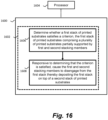
- Figure 16 shows an example of such a non-transitory computer-readable storage medium 1600 comprising a set of computer readable instructions 802 which, when executed by at least one processor 804, cause the processor(s) 804 to perform a method according to examples described herein.
- the computer readable instructions 800 may be retrieved from a machine-readable media, e.g. any media that can contain, store, or maintain programs and data for use by or in connection with an instruction execution system.
- machine-readable media can comprise any one of many physical media such as, for example, electronic, magnetic, optical, electromagnetic, or semiconductor media. More specific examples of suitable machine-readable media include, but are not limited to, a hard drive, a random access memory (RAM), a read-only memory (ROM), an erasable programmable read-only memory, or a portable disc.
- RAM random access memory
- ROM read-only memory
- erasable programmable read-only memory or a portable disc.
- instructions 1602 cause the processor 1604 in a stacking system to, at block 1606 determine whether a first stack of printed substrates satisfies a criterion, the first stack of printed substrates comprising a plurality of printed substrates partially supported by first and second stacking members.
- the instructions 1602 cause the processor 1604 to, responsive to determining that the criterion is satisfied, cause the first and second stacking members to disengage from the first stack thereby depositing the first stack on top of a second stack of printed substrates.
Landscapes
- Engineering & Computer Science (AREA)
- Mechanical Engineering (AREA)
- Pile Receivers (AREA)
Claims (12)
- Verfahren (1500) zum Stapeln bedruckter Substrate (108, 202), wobei das Verfahren Folgendes umfasst:sequenzielles Aufnehmen (1502) einer Vielzahl bedruckter Substrate;Stapeln (1504) der Vielzahl bedruckter Substrate auf einem ersten Stapelelement (206, 806) und einem zweiten Stapelelement (208, 808), um einen ersten Stapel (212, 812) zu erzeugen, wobei die Vielzahl bedruckter Substrate teilweise durch das erste und das zweite Stapelelement getragen wird und teilweise durch einen zweiten Stapel (220, 820) getragen wird, wobei der zweite Stapel zuvor gestapelte bedruckte Substrate umfasst;Bestimmen (1508), dass der erste Stapel ein Kriterium erfüllt; undals Reaktion auf ein Bestimmen, dass das Kriterium erfüllt ist, Lösen (1508) des ersten Stapelelements und des zweiten Stapelelements von dem ersten Stapel, wobei dadurch die Vielzahl bedruckter Substrate auf dem zweiten Stapel abgelegt wird.
- Verfahren nach Anspruch 1, wobei das Verfahren ferner ein Hin- und Herbewegen des ersten Stapels umfasst, um die Vielzahl bedruckter Substrate auszurichten.
- Verfahren nach Anspruch 2, wobei ein Hin- und Herbewegen des ersten Stapels mindestens eines von Folgendem umfasst:Vibrierenlassen eines oder mehrerer des ersten und des zweiten Stapelelements entlang einer ersten Achse, um die Vielzahl von Substraten entlang der ersten Achse auszurichten; undVibrierenlassen eines oder mehrerer eines ersten Endelements (830) und eines zweiten Endelements (832) entlang einer zweiten Achse, die senkrecht zu der ersten Achse ist, um die Vielzahl von Substraten entlang der zweiten Achse auszurichten.
- Verfahren nach Anspruch 1, das ferner Folgendes umfasst:
Versetzen des ersten Stapels von dem zweiten Stapel entlang einer zweiten Achse durch Anpassen einer Position von mindestens einem von einem ersten Endelement und einem zweiten Endelement entlang der zweiten Achse, wobei das erste und das zweite Endelement voneinander beabstandet und parallel zueinander sind. - Verfahren nach Anspruch 1, wobei das Verfahren ein Überwachen von mindestens einem von Folgendem umfasst:einem Zählwert der Vielzahl bedruckter Substrate und wobei das Kriterium erfüllt ist, wenn der Zählwert der Vielzahl bedruckter Substrate einen vorbestimmten Schwellenzählwert erreicht;einer Höhenabmessung der Vielzahl bedruckter Substrate und wobei das Kriterium erfüllt ist, wenn die Höhenabmessung der Vielzahl bedruckter Substrate eine vorbestimmte Schwellenhöhe erreicht; undeiner Masse der Vielzahl bedruckter Substrate und wobei das Kriterium erfüllt ist, wenn die Masse der Vielzahl bedruckter Substrate eine vorbestimmte Schwellenmasse erreicht.
- Stapelsystem für bedruckte Substrate (108, 202), wobei das Stapelsystem Folgendes umfasst:ein Stapelelement (206, 208, 806, 808), das zwischen einer ersten Position, in der das Stapelelement dazu konfiguriert ist, einen ersten Stapel (212, 812) bedruckter Substrate teilweise zu tragen, und einer zweiten Position, in der das Stapelelement von dem ersten Stapel gelöst ist, bewegbar ist;eine Aufnahme (222, 822), die unterhalb des Stapelelements positioniert und dazu konfiguriert ist, einen zweiten Stapel (220, 820) bedruckter Substrate zu halten;ein Bedienungselement (224), das dazu konfiguriert ist, die Aufnahme entlang einer vertikalen Achse zu bewegen; undeine Steuerung (112), die für Folgendes konfiguriert ist:derartiges Anpassen einer Position der Aufnahme entlang der vertikalen Achse, dass der zweite Stapel bedruckter Substrate positioniert ist, um den ersten Stapel bedruckter Substrate teilweise zu tragen, während sich das Stapelelement in der ersten Position befindet; undVeranlassen des Stapelelements, sich zwischen der ersten Position und der zweiten Position zu bewegen, wenn der erste Stapel ein Kriterium erfüllt, wobei dadurch der erste Stapel in die Aufnahme oben auf dem zweiten Stapel abgelegt wird.
- Stapelsystem nach Anspruch 6, wobei das Stapelelement ein erstes Stapelelement ist und das System ferner Folgendes umfasst:ein zweites Stapelelement (208, 808), das zwischen einer dritten Position, in der das zweite Stapelelement dazu konfiguriert ist, den ersten Stapel bedruckter Substrate teilweise zu tragen, und einer vierten Position, in der das zweite Stapelelement von dem ersten Stapel gelöst ist, bewegbar ist;wobei die Steuerung dazu konfiguriert ist, das zweite Stapelelement zu veranlassen, sich zwischen der dritten Position und der vierten Position zu bewegen, wenn der erste Stapel das Kriterium erfüllt.
- Stapelsystem nach Anspruch 7, wobei die Steuerung dazu konfiguriert ist, mindestens eines von dem ersten und dem zweiten Stapelelement zu veranlassen, entlang einer ersten Achse zu vibrieren, um die Vielzahl bedruckter Substrate entlang der ersten Achse auszurichten.
- Stapelsystem nach Anspruch 8, das ferner Folgendes umfasst:ein erstes Endelement, das angrenzend an eine Vorderkante des ersten Stapels positioniert ist; undein zweites Endelement, das angrenzend an eine Hinterkante des ersten Stapels positioniert ist;wobei die Steuerung dazu konfiguriert ist, Folgendes zu veranlassen:
mindestens eines von dem ersten und dem zweiten Endelement entlang einer zweiten Achse vibrieren zu lassen, die senkrecht zu der ersten Achse ist, um die Vielzahl bedruckter Substrate entlang der zweiten Achse auszurichten. - System nach Anspruch 7, das ferner Folgendes umfasst:ein erstes Endelement (830), das angrenzend an eine Vorderkante des ersten Stapels positioniert ist; undein zweites Endelement (832), das angrenzend an eine Hinterkante des ersten Stapels positioniert ist;wobei die Steuerung für mindestens eines von Folgendem konfiguriert ist:Anpassen einer Position von mindestens einem von dem ersten und dem zweiten Stapelelement entlang einer ersten Achse, um den ersten Stapel entlang der ersten Achse von dem zweiten Stapel zu versetzen; undAnpassen einer Position von mindestens einem von dem ersten und dem zweiten Endelement entlang einer zweiten Achse, die senkrecht zu der ersten Achse ist, um den ersten Stapel entlang der zweiten Achse von dem zweiten Stapel zu versetzen, wobei das erste und das zweite Endelement parallel zu der ersten Achse angeordnet sind.
- System nach Anspruch 10, wobei die Steuerung für Folgendes konfiguriert ist:
Anpassen eines Abstands zwischen dem ersten und dem zweiten Stapelelement auf der Basis von einer Größenabmessung der bedruckten Substrate durch Veranlassen von mindestens einem von dem ersten und dem zweiten Stapelelement, sich entlang der ersten Achse zu bewegen. - Nichtflüchtiges computerlesbares Speichermedium (1600), das Anweisungen (1602) speichert, die, wenn sie durch einen Prozessor oder mehrere Prozessoren (1604) in einem Stapelsystem nach Anspruch 6 ausgeführt werden, den einen Prozessor oder die mehreren Prozessoren zu Folgendem veranlassen:Bestimmen, ob der erste Stapel bedruckter Substrate das Kriterium erfüllt, wobei der erste Stapel bedruckter Substrate eine Vielzahl bedruckter Substrate umfasst, die teilweise durch das Stapelelement und teilweise durch den zweiten Stapel bedruckter Substrate getragen werden; undals Reaktion auf ein Bestimmen, dass das Kriterium erfüllt ist, Veranlassen des Stapelelements, sich von dem ersten Stapel zu lösen, wobei dadurch der erste Stapel oben auf dem zweiten Stapel bedruckter Substrate abgelegt wird.
Applications Claiming Priority (1)
| Application Number | Priority Date | Filing Date | Title |
|---|---|---|---|
| PCT/US2017/066202 WO2019117898A1 (en) | 2017-12-13 | 2017-12-13 | Method and system for stacking printed substrates |
Publications (3)
| Publication Number | Publication Date |
|---|---|
| EP3677102A1 EP3677102A1 (de) | 2020-07-08 |
| EP3677102A4 EP3677102A4 (de) | 2021-04-21 |
| EP3677102B1 true EP3677102B1 (de) | 2024-11-06 |
Family
ID=66820480
Family Applications (1)
| Application Number | Title | Priority Date | Filing Date |
|---|---|---|---|
| EP17934962.6A Active EP3677102B1 (de) | 2017-12-13 | 2017-12-13 | Verfahren und system zum stapeln von bedruckten substraten |
Country Status (4)
| Country | Link |
|---|---|
| US (1) | US11148898B2 (de) |
| EP (1) | EP3677102B1 (de) |
| CN (1) | CN111295934A (de) |
| WO (1) | WO2019117898A1 (de) |
Families Citing this family (5)
| Publication number | Priority date | Publication date | Assignee | Title |
|---|---|---|---|---|
| WO2019221719A1 (en) * | 2018-05-15 | 2019-11-21 | Hewlett-Packard Development Company, L.P. | Media stacking mechanisms |
| CN112277436A (zh) * | 2020-11-02 | 2021-01-29 | 李连学 | 一种可调直径的丝网印刷设备 |
| HUE067121T2 (hu) * | 2021-09-17 | 2024-10-28 | Grob Gmbh & Co Kg | Pozícionáló eszköz, kötegelõ eszköz és kötegelõ eljárás akkumulátor- vagy üzemanyagcellák számára szolgáló cellaköteg ismétlõdõ komponenseihez |
| JP2024153350A (ja) * | 2023-04-17 | 2024-10-29 | 理想科学工業株式会社 | 媒体積載装置 |
| US20250304400A1 (en) * | 2024-03-27 | 2025-10-02 | Ncr Atleos Corporation | Apparatus and method for moveable guide |
Family Cites Families (21)
| Publication number | Priority date | Publication date | Assignee | Title |
|---|---|---|---|---|
| US3651961A (en) * | 1970-03-16 | 1972-03-28 | Potlatch Forests Inc | Sheet material accumulator |
| US3951264A (en) * | 1974-10-29 | 1976-04-20 | Dynastor, Inc. | Flexible disc cartridge |
| US4475730A (en) | 1983-03-23 | 1984-10-09 | C.G. Bretting Mfg. Co., Inc. | Apparatus for folding and stacking paper products |
| JP2583693B2 (ja) * | 1990-11-20 | 1997-02-19 | グンゼ株式会社 | 刷本の処理装置 |
| JPH04209138A (ja) | 1990-11-30 | 1992-07-30 | Toshiba Corp | 給紙カセット並びにこの給紙カセットを用いた画像形成装置 |
| DE4204987C2 (de) * | 1992-02-19 | 1995-04-13 | Natec Reich Summer Gmbh Co Kg | Vorrichtung zum Schneiden und Abstapeln von scheibenförmigen Einzelpackungen |
| US5553536A (en) | 1994-10-03 | 1996-09-10 | Van Os Enterprises | Screen printing apparatus with vacuum conveyor belt |
| US5671920A (en) * | 1995-06-01 | 1997-09-30 | Xerox Corporation | High speed printed sheet stacking and registration system |
| US6102842A (en) | 1997-09-08 | 2000-08-15 | Harris, Jr.; Walter E. | Adjustable continuous forms paper stacker |
| KR100480463B1 (ko) * | 1998-09-17 | 2005-09-12 | 주식회사신도리코 | 용지후처리장치 |
| US6394443B1 (en) * | 2000-11-02 | 2002-05-28 | Multifeeder Technology, Inc. | Drop table attachment for sheet feeding machine |
| US6625530B1 (en) | 2000-11-06 | 2003-09-23 | Delphi Technologies, Inc. | Feed forward—feed back control for steer-by-wire system |
| US7081373B2 (en) * | 2001-12-14 | 2006-07-25 | Staktek Group, L.P. | CSP chip stack with flex circuit |
| US6722650B1 (en) * | 2003-02-21 | 2004-04-20 | Xerox Corporation | Systems and methods for trail edge paper suppression for high-speed finishing applications |
| US6819906B1 (en) * | 2003-08-29 | 2004-11-16 | Xerox Corporation | Printer output sets compiler to stacker system |
| US7213807B2 (en) | 2003-11-07 | 2007-05-08 | Paxar Americase, Inc. | Stacker and method of batch separation with sheets |
| JP2006096444A (ja) * | 2004-09-28 | 2006-04-13 | Toshiba Tec Corp | シート後処理装置 |
| JP4525730B2 (ja) * | 2007-10-29 | 2010-08-18 | 富士ゼロックス株式会社 | 後処理装置及び画像形成装置 |
| JP5234345B2 (ja) | 2008-02-12 | 2013-07-10 | 株式会社リコー | 積載用紙整合装置、排紙装置、画像形成装置 |
| US8100393B2 (en) | 2010-02-01 | 2012-01-24 | Xerox Corporation | Sawtooth jog for multi-copy/multi-set output |
| JP6103945B2 (ja) * | 2013-01-10 | 2017-03-29 | ユニ・チャーム株式会社 | 積み重ね装置及びウェブ部材を製造する方法 |
-
2017
- 2017-12-13 EP EP17934962.6A patent/EP3677102B1/de active Active
- 2017-12-13 WO PCT/US2017/066202 patent/WO2019117898A1/en not_active Ceased
- 2017-12-13 CN CN201780096481.2A patent/CN111295934A/zh active Pending
- 2017-12-13 US US16/605,894 patent/US11148898B2/en active Active
Also Published As
| Publication number | Publication date |
|---|---|
| CN111295934A (zh) | 2020-06-16 |
| EP3677102A1 (de) | 2020-07-08 |
| EP3677102A4 (de) | 2021-04-21 |
| US20210094784A1 (en) | 2021-04-01 |
| WO2019117898A1 (en) | 2019-06-20 |
| US11148898B2 (en) | 2021-10-19 |
Similar Documents
| Publication | Publication Date | Title |
|---|---|---|
| EP3677102B1 (de) | Verfahren und system zum stapeln von bedruckten substraten | |
| US7651089B2 (en) | Method and device for forming stacks of flat elements | |
| EP3354609B1 (de) | Transportvorrichtung und druckvorrichtung | |
| CN106458483B (zh) | 供给板状元件的方法、供给台及由此配备的加工机 | |
| US11613387B2 (en) | Vibrating device for the orderly rearrangement of folding boxes in a container, discharging conveyor and method for discharging containers | |
| KR102688036B1 (ko) | 트랜스포머 코어의 제조 방법 및 포지셔닝 시스템 | |
| US20130256972A1 (en) | Pneumatic sheet registration and clamping | |
| US10414607B2 (en) | Portioning system for portioning stackable flat elements in a stack for a further processing | |
| EP3233679B1 (de) | Handhabungsystem zum handhaben eines stapels von stapelbaren flächigen elementen | |
| CN110589501B (zh) | 一种自动堆栈设备 | |
| CN104909188B (zh) | 叠堆提升装置 | |
| JP5907853B2 (ja) | 補助パイルを形成する方法および装置 | |
| US7775514B2 (en) | Sheet post-processing apparatus | |
| KR102037808B1 (ko) | 비드―에이펙스 공정을 위한 조립체 및 방법 | |
| JP7022084B2 (ja) | ワーク搬送システム、搬送ワーク枚数検出装置及びワーク搬送システムの制御方法 | |
| CN114641444A (zh) | 具有单张纸加工机和至少一个排齐装置的基材处理系统以及用于排齐和/或分散单张纸的至少一个子堆垛的方法 | |
| JP2007084301A (ja) | 用紙後処理装置 | |
| CN110589502B (zh) | 一种堆栈方法 | |
| JP6734815B2 (ja) | 刷版処理装置 | |
| US20240375806A1 (en) | Blank Separating Device, Corresponding Packaging Machine, and Method for Producing Separated Blanks from a Stack | |
| EP4685094A1 (de) | Blattzuführvorrichtung | |
| JP4703914B2 (ja) | シート整列装置 | |
| EP3865435B1 (de) | System zum stapeln von faltschachteln | |
| JP2024089631A (ja) | プリンタ用のシートスタッカおよび/またはシートフィーダを備えるシートスタックハンドラ | |
| JP2026020026A (ja) | 給紙装置 |
Legal Events
| Date | Code | Title | Description |
|---|---|---|---|
| STAA | Information on the status of an ep patent application or granted ep patent |
Free format text: STATUS: THE INTERNATIONAL PUBLICATION HAS BEEN MADE |
|
| PUAI | Public reference made under article 153(3) epc to a published international application that has entered the european phase |
Free format text: ORIGINAL CODE: 0009012 |
|
| STAA | Information on the status of an ep patent application or granted ep patent |
Free format text: STATUS: REQUEST FOR EXAMINATION WAS MADE |
|
| 17P | Request for examination filed |
Effective date: 20200401 |
|
| AK | Designated contracting states |
Kind code of ref document: A1 Designated state(s): AL AT BE BG CH CY CZ DE DK EE ES FI FR GB GR HR HU IE IS IT LI LT LU LV MC MK MT NL NO PL PT RO RS SE SI SK SM TR |
|
| AX | Request for extension of the european patent |
Extension state: BA ME |
|
| DAV | Request for validation of the european patent (deleted) | ||
| DAX | Request for extension of the european patent (deleted) | ||
| A4 | Supplementary search report drawn up and despatched |
Effective date: 20210318 |
|
| RIC1 | Information provided on ipc code assigned before grant |
Ipc: H05K 3/36 20060101AFI20210312BHEP Ipc: B41F 15/00 20060101ALI20210312BHEP Ipc: B65H 31/30 20060101ALI20210312BHEP Ipc: B65H 31/38 20060101ALI20210312BHEP |
|
| STAA | Information on the status of an ep patent application or granted ep patent |
Free format text: STATUS: EXAMINATION IS IN PROGRESS |
|
| 17Q | First examination report despatched |
Effective date: 20221005 |
|
| REG | Reference to a national code |
Ref country code: DE Ref legal event code: R079 Free format text: PREVIOUS MAIN CLASS: H05K0003360000 Ipc: B65H0029340000 Ref country code: DE Ref legal event code: R079 Ref document number: 602017086035 Country of ref document: DE Free format text: PREVIOUS MAIN CLASS: H05K0003360000 Ipc: B65H0029340000 |
|
| GRAP | Despatch of communication of intention to grant a patent |
Free format text: ORIGINAL CODE: EPIDOSNIGR1 |
|
| STAA | Information on the status of an ep patent application or granted ep patent |
Free format text: STATUS: GRANT OF PATENT IS INTENDED |
|
| RIC1 | Information provided on ipc code assigned before grant |
Ipc: H05K 3/12 20060101ALI20240717BHEP Ipc: B65H 31/38 20060101ALI20240717BHEP Ipc: B65H 31/30 20060101ALI20240717BHEP Ipc: B65H 43/06 20060101ALI20240717BHEP Ipc: B65H 33/08 20060101ALI20240717BHEP Ipc: B65H 31/20 20060101ALI20240717BHEP Ipc: B65H 31/10 20060101ALI20240717BHEP Ipc: B65H 31/02 20060101ALI20240717BHEP Ipc: B65H 29/34 20060101AFI20240717BHEP |
|
| INTG | Intention to grant announced |
Effective date: 20240806 |
|
| GRAS | Grant fee paid |
Free format text: ORIGINAL CODE: EPIDOSNIGR3 |
|
| GRAA | (expected) grant |
Free format text: ORIGINAL CODE: 0009210 |
|
| STAA | Information on the status of an ep patent application or granted ep patent |
Free format text: STATUS: THE PATENT HAS BEEN GRANTED |
|
| AK | Designated contracting states |
Kind code of ref document: B1 Designated state(s): AL AT BE BG CH CY CZ DE DK EE ES FI FR GB GR HR HU IE IS IT LI LT LU LV MC MK MT NL NO PL PT RO RS SE SI SK SM TR |
|
| REG | Reference to a national code |
Ref country code: GB Ref legal event code: FG4D |
|
| REG | Reference to a national code |
Ref country code: CH Ref legal event code: EP |
|
| REG | Reference to a national code |
Ref country code: DE Ref legal event code: R096 Ref document number: 602017086035 Country of ref document: DE |
|
| REG | Reference to a national code |
Ref country code: IE Ref legal event code: FG4D |
|
| REG | Reference to a national code |
Ref country code: LT Ref legal event code: MG9D |
|
| REG | Reference to a national code |
Ref country code: NL Ref legal event code: MP Effective date: 20241106 |
|
| PG25 | Lapsed in a contracting state [announced via postgrant information from national office to epo] |
Ref country code: PT Free format text: LAPSE BECAUSE OF FAILURE TO SUBMIT A TRANSLATION OF THE DESCRIPTION OR TO PAY THE FEE WITHIN THE PRESCRIBED TIME-LIMIT Effective date: 20250306 Ref country code: IS Free format text: LAPSE BECAUSE OF FAILURE TO SUBMIT A TRANSLATION OF THE DESCRIPTION OR TO PAY THE FEE WITHIN THE PRESCRIBED TIME-LIMIT Effective date: 20250306 Ref country code: HR Free format text: LAPSE BECAUSE OF FAILURE TO SUBMIT A TRANSLATION OF THE DESCRIPTION OR TO PAY THE FEE WITHIN THE PRESCRIBED TIME-LIMIT Effective date: 20241106 |
|
| PG25 | Lapsed in a contracting state [announced via postgrant information from national office to epo] |
Ref country code: FI Free format text: LAPSE BECAUSE OF FAILURE TO SUBMIT A TRANSLATION OF THE DESCRIPTION OR TO PAY THE FEE WITHIN THE PRESCRIBED TIME-LIMIT Effective date: 20241106 Ref country code: NL Free format text: LAPSE BECAUSE OF FAILURE TO SUBMIT A TRANSLATION OF THE DESCRIPTION OR TO PAY THE FEE WITHIN THE PRESCRIBED TIME-LIMIT Effective date: 20241106 |
|
| REG | Reference to a national code |
Ref country code: AT Ref legal event code: MK05 Ref document number: 1739185 Country of ref document: AT Kind code of ref document: T Effective date: 20241106 |
|
| PG25 | Lapsed in a contracting state [announced via postgrant information from national office to epo] |
Ref country code: BG Free format text: LAPSE BECAUSE OF FAILURE TO SUBMIT A TRANSLATION OF THE DESCRIPTION OR TO PAY THE FEE WITHIN THE PRESCRIBED TIME-LIMIT Effective date: 20241106 |
|
| PG25 | Lapsed in a contracting state [announced via postgrant information from national office to epo] |
Ref country code: ES Free format text: LAPSE BECAUSE OF FAILURE TO SUBMIT A TRANSLATION OF THE DESCRIPTION OR TO PAY THE FEE WITHIN THE PRESCRIBED TIME-LIMIT Effective date: 20241106 |
|
| PG25 | Lapsed in a contracting state [announced via postgrant information from national office to epo] |
Ref country code: NO Free format text: LAPSE BECAUSE OF FAILURE TO SUBMIT A TRANSLATION OF THE DESCRIPTION OR TO PAY THE FEE WITHIN THE PRESCRIBED TIME-LIMIT Effective date: 20250206 |
|
| PG25 | Lapsed in a contracting state [announced via postgrant information from national office to epo] |
Ref country code: GR Free format text: LAPSE BECAUSE OF FAILURE TO SUBMIT A TRANSLATION OF THE DESCRIPTION OR TO PAY THE FEE WITHIN THE PRESCRIBED TIME-LIMIT Effective date: 20250207 Ref country code: LV Free format text: LAPSE BECAUSE OF FAILURE TO SUBMIT A TRANSLATION OF THE DESCRIPTION OR TO PAY THE FEE WITHIN THE PRESCRIBED TIME-LIMIT Effective date: 20241106 Ref country code: AT Free format text: LAPSE BECAUSE OF FAILURE TO SUBMIT A TRANSLATION OF THE DESCRIPTION OR TO PAY THE FEE WITHIN THE PRESCRIBED TIME-LIMIT Effective date: 20241106 |
|
| PG25 | Lapsed in a contracting state [announced via postgrant information from national office to epo] |
Ref country code: PL Free format text: LAPSE BECAUSE OF FAILURE TO SUBMIT A TRANSLATION OF THE DESCRIPTION OR TO PAY THE FEE WITHIN THE PRESCRIBED TIME-LIMIT Effective date: 20241106 |
|
| PG25 | Lapsed in a contracting state [announced via postgrant information from national office to epo] |
Ref country code: RS Free format text: LAPSE BECAUSE OF FAILURE TO SUBMIT A TRANSLATION OF THE DESCRIPTION OR TO PAY THE FEE WITHIN THE PRESCRIBED TIME-LIMIT Effective date: 20250206 |
|
| PG25 | Lapsed in a contracting state [announced via postgrant information from national office to epo] |
Ref country code: SM Free format text: LAPSE BECAUSE OF FAILURE TO SUBMIT A TRANSLATION OF THE DESCRIPTION OR TO PAY THE FEE WITHIN THE PRESCRIBED TIME-LIMIT Effective date: 20241106 |
|
| PG25 | Lapsed in a contracting state [announced via postgrant information from national office to epo] |
Ref country code: DK Free format text: LAPSE BECAUSE OF FAILURE TO SUBMIT A TRANSLATION OF THE DESCRIPTION OR TO PAY THE FEE WITHIN THE PRESCRIBED TIME-LIMIT Effective date: 20241106 |
|
| PG25 | Lapsed in a contracting state [announced via postgrant information from national office to epo] |
Ref country code: EE Free format text: LAPSE BECAUSE OF FAILURE TO SUBMIT A TRANSLATION OF THE DESCRIPTION OR TO PAY THE FEE WITHIN THE PRESCRIBED TIME-LIMIT Effective date: 20241106 |
|
| PG25 | Lapsed in a contracting state [announced via postgrant information from national office to epo] |
Ref country code: RO Free format text: LAPSE BECAUSE OF FAILURE TO SUBMIT A TRANSLATION OF THE DESCRIPTION OR TO PAY THE FEE WITHIN THE PRESCRIBED TIME-LIMIT Effective date: 20241106 |
|
| PG25 | Lapsed in a contracting state [announced via postgrant information from national office to epo] |
Ref country code: SK Free format text: LAPSE BECAUSE OF FAILURE TO SUBMIT A TRANSLATION OF THE DESCRIPTION OR TO PAY THE FEE WITHIN THE PRESCRIBED TIME-LIMIT Effective date: 20241106 |
|
| PG25 | Lapsed in a contracting state [announced via postgrant information from national office to epo] |
Ref country code: CZ Free format text: LAPSE BECAUSE OF FAILURE TO SUBMIT A TRANSLATION OF THE DESCRIPTION OR TO PAY THE FEE WITHIN THE PRESCRIBED TIME-LIMIT Effective date: 20241106 |
|
| PG25 | Lapsed in a contracting state [announced via postgrant information from national office to epo] |
Ref country code: IT Free format text: LAPSE BECAUSE OF FAILURE TO SUBMIT A TRANSLATION OF THE DESCRIPTION OR TO PAY THE FEE WITHIN THE PRESCRIBED TIME-LIMIT Effective date: 20241106 |
|
| REG | Reference to a national code |
Ref country code: CH Ref legal event code: PL |
|
| REG | Reference to a national code |
Ref country code: DE Ref legal event code: R097 Ref document number: 602017086035 Country of ref document: DE |
|
| PG25 | Lapsed in a contracting state [announced via postgrant information from national office to epo] |
Ref country code: LU Free format text: LAPSE BECAUSE OF NON-PAYMENT OF DUE FEES Effective date: 20241213 |
|
| PG25 | Lapsed in a contracting state [announced via postgrant information from national office to epo] |
Ref country code: SE Free format text: LAPSE BECAUSE OF FAILURE TO SUBMIT A TRANSLATION OF THE DESCRIPTION OR TO PAY THE FEE WITHIN THE PRESCRIBED TIME-LIMIT Effective date: 20241106 |
|
| PLBE | No opposition filed within time limit |
Free format text: ORIGINAL CODE: 0009261 |
|
| STAA | Information on the status of an ep patent application or granted ep patent |
Free format text: STATUS: NO OPPOSITION FILED WITHIN TIME LIMIT |
|
| PG25 | Lapsed in a contracting state [announced via postgrant information from national office to epo] |
Ref country code: MC Free format text: LAPSE BECAUSE OF FAILURE TO SUBMIT A TRANSLATION OF THE DESCRIPTION OR TO PAY THE FEE WITHIN THE PRESCRIBED TIME-LIMIT Effective date: 20241106 |
|
| REG | Reference to a national code |
Ref country code: BE Ref legal event code: MM Effective date: 20241231 |
|
| 26N | No opposition filed |
Effective date: 20250807 |
|
| PG25 | Lapsed in a contracting state [announced via postgrant information from national office to epo] |
Ref country code: BE Free format text: LAPSE BECAUSE OF NON-PAYMENT OF DUE FEES Effective date: 20241231 |
|
| PG25 | Lapsed in a contracting state [announced via postgrant information from national office to epo] |
Ref country code: FR Free format text: LAPSE BECAUSE OF NON-PAYMENT OF DUE FEES Effective date: 20250106 |
|
| PG25 | Lapsed in a contracting state [announced via postgrant information from national office to epo] |
Ref country code: CH Free format text: LAPSE BECAUSE OF NON-PAYMENT OF DUE FEES Effective date: 20241231 |
|
| PG25 | Lapsed in a contracting state [announced via postgrant information from national office to epo] |
Ref country code: IE Free format text: LAPSE BECAUSE OF NON-PAYMENT OF DUE FEES Effective date: 20241213 |
|
| GBPC | Gb: european patent ceased through non-payment of renewal fee |
Effective date: 20250206 |
|
| PGFP | Annual fee paid to national office [announced via postgrant information from national office to epo] |
Ref country code: DE Payment date: 20251126 Year of fee payment: 9 |
|
| PG25 | Lapsed in a contracting state [announced via postgrant information from national office to epo] |
Ref country code: GB Free format text: LAPSE BECAUSE OF NON-PAYMENT OF DUE FEES Effective date: 20250206 |