EP3676489B1 - Einspritzventilanordnung - Google Patents
Einspritzventilanordnung Download PDFInfo
- Publication number
- EP3676489B1 EP3676489B1 EP18735287.7A EP18735287A EP3676489B1 EP 3676489 B1 EP3676489 B1 EP 3676489B1 EP 18735287 A EP18735287 A EP 18735287A EP 3676489 B1 EP3676489 B1 EP 3676489B1
- Authority
- EP
- European Patent Office
- Prior art keywords
- housing
- injection valve
- injection
- connecting region
- area
- Prior art date
- Legal status (The legal status is an assumption and is not a legal conclusion. Google has not performed a legal analysis and makes no representation as to the accuracy of the status listed.)
- Active
Links
Images



Classifications
-
- F—MECHANICAL ENGINEERING; LIGHTING; HEATING; WEAPONS; BLASTING
- F02—COMBUSTION ENGINES; HOT-GAS OR COMBUSTION-PRODUCT ENGINE PLANTS
- F02M—SUPPLYING COMBUSTION ENGINES IN GENERAL WITH COMBUSTIBLE MIXTURES OR CONSTITUENTS THEREOF
- F02M61/00—Fuel-injectors not provided for in groups F02M39/00 - F02M57/00 or F02M67/00
- F02M61/16—Details not provided for in, or of interest apart from, the apparatus of groups F02M61/02 - F02M61/14
- F02M61/168—Assembling; Disassembling; Manufacturing; Adjusting
-
- F—MECHANICAL ENGINEERING; LIGHTING; HEATING; WEAPONS; BLASTING
- F02—COMBUSTION ENGINES; HOT-GAS OR COMBUSTION-PRODUCT ENGINE PLANTS
- F02M—SUPPLYING COMBUSTION ENGINES IN GENERAL WITH COMBUSTIBLE MIXTURES OR CONSTITUENTS THEREOF
- F02M61/00—Fuel-injectors not provided for in groups F02M39/00 - F02M57/00 or F02M67/00
- F02M61/14—Arrangements of injectors with respect to engines; Mounting of injectors
-
- F—MECHANICAL ENGINEERING; LIGHTING; HEATING; WEAPONS; BLASTING
- F02—COMBUSTION ENGINES; HOT-GAS OR COMBUSTION-PRODUCT ENGINE PLANTS
- F02M—SUPPLYING COMBUSTION ENGINES IN GENERAL WITH COMBUSTIBLE MIXTURES OR CONSTITUENTS THEREOF
- F02M2200/00—Details of fuel-injection apparatus, not otherwise provided for
- F02M2200/80—Fuel injection apparatus manufacture, repair or assembly
- F02M2200/8046—Fuel injection apparatus manufacture, repair or assembly the manufacture involving injection moulding, e.g. of plastic or metal
-
- F—MECHANICAL ENGINEERING; LIGHTING; HEATING; WEAPONS; BLASTING
- F02—COMBUSTION ENGINES; HOT-GAS OR COMBUSTION-PRODUCT ENGINE PLANTS
- F02M—SUPPLYING COMBUSTION ENGINES IN GENERAL WITH COMBUSTIBLE MIXTURES OR CONSTITUENTS THEREOF
- F02M2200/00—Details of fuel-injection apparatus, not otherwise provided for
- F02M2200/80—Fuel injection apparatus manufacture, repair or assembly
- F02M2200/8061—Fuel injection apparatus manufacture, repair or assembly involving press-fit, i.e. interference or friction fit
-
- F—MECHANICAL ENGINEERING; LIGHTING; HEATING; WEAPONS; BLASTING
- F02—COMBUSTION ENGINES; HOT-GAS OR COMBUSTION-PRODUCT ENGINE PLANTS
- F02M—SUPPLYING COMBUSTION ENGINES IN GENERAL WITH COMBUSTIBLE MIXTURES OR CONSTITUENTS THEREOF
- F02M2200/00—Details of fuel-injection apparatus, not otherwise provided for
- F02M2200/85—Mounting of fuel injection apparatus
- F02M2200/856—Mounting of fuel injection apparatus characterised by mounting injector to fuel or common rail, or vice versa
-
- F—MECHANICAL ENGINEERING; LIGHTING; HEATING; WEAPONS; BLASTING
- F02—COMBUSTION ENGINES; HOT-GAS OR COMBUSTION-PRODUCT ENGINE PLANTS
- F02M—SUPPLYING COMBUSTION ENGINES IN GENERAL WITH COMBUSTIBLE MIXTURES OR CONSTITUENTS THEREOF
- F02M55/00—Fuel-injection apparatus characterised by their fuel conduits or their venting means; Arrangements of conduits between fuel tank and pump F02M37/00
- F02M55/02—Conduits between injection pumps and injectors, e.g. conduits between pump and common-rail or conduits between common-rail and injectors
- F02M55/025—Common rails
-
- F—MECHANICAL ENGINEERING; LIGHTING; HEATING; WEAPONS; BLASTING
- F02—COMBUSTION ENGINES; HOT-GAS OR COMBUSTION-PRODUCT ENGINE PLANTS
- F02M—SUPPLYING COMBUSTION ENGINES IN GENERAL WITH COMBUSTIBLE MIXTURES OR CONSTITUENTS THEREOF
- F02M69/00—Low-pressure fuel-injection apparatus ; Apparatus with both continuous and intermittent injection; Apparatus injecting different types of fuel
- F02M69/46—Details, component parts or accessories not provided for in, or of interest apart from, the apparatus covered by groups F02M69/02 - F02M69/44
- F02M69/462—Arrangement of fuel conduits, e.g. with valves for maintaining pressure in the pipes after the engine being shut-down
- F02M69/465—Arrangement of fuel conduits, e.g. with valves for maintaining pressure in the pipes after the engine being shut-down of fuel rails
Definitions
- the present invention relates to an injection arrangement with an injection valve for injecting a fluid, in particular a fuel injection valve arrangement.
- a connecting piece In order to connect the injection valve to an area of the internal combustion engine, in particular to a rail cup of a common rail, a connecting piece is used, with a holding force required for holding the injection valve being provided by a holding element.
- the holding force of the holding element is transferred either directly to a housing which surrounds the injection valve or to a washer welded to the housing.
- the housing can settle, as a result of which a distance between the injection valve and the area of the internal combustion engine increases, and the holding element leaves its working area. Dangerous stresses and strains can occur in the housing, which can lead to cracks. The cracks lead to leakage of the housing from moisture.
- the disc is an additional component that must first be positioned and then welded.
- an injection valve arrangement in particular a fuel injection valve arrangement, which comprises an injection valve, a plastic housing which at least partially surrounds the injection valve, and a connecting piece which is an overmolded part of the injection valve.
- the connecting piece has a central area as a connection area, which has a radially outwardly projecting annular collar and via which the injection valve is arranged in a form-fitting manner on the housing.
- the housing is designed as an overmoulding part in the form of a plastic overmoulding.
- the injection valve arrangement according to the invention which is designed in particular as a fuel injection valve arrangement, has the advantage of a simple and robust structure. According to the invention, this is achieved by an injection valve arrangement which comprises an injection valve, a housing which at least partially surrounds the injection valve, and a connecting piece.
- the connecting piece is connected to the injection valve and has a connection area, via which the injection valve is arranged in a form-fitting manner on the housing.
- the positive connection between the injection valve and the housing prevents the housing from settling.
- the form-fitting connection prevents movement of the housing during expansion or contraction, particularly in the event of temperature changes. Thus, the strength of the housing is maintained and leaks are avoided.
- the connecting piece which serves as the interface to the area of the internal combustion engine, in particular to the rail cup, and at the same time supports the housing. This saves an additional component and an additional process for positioning this component in the injection assembly.
- the production of such a connecting piece is simple and very inexpensive.
- the connecting piece is preferably welded to the housing.
- connection area preferably has a collar which extends radially outwards.
- connection area has a first end and a second end, the first end being arranged in front of the second end in the injection direction.
- the first end is an end on the rail side, the second end being an end on the combustion chamber side.
- the first end is one in a mounted state of the injector in an internal combustion engine Facing common rail, the second end facing a combustion chamber of the internal combustion engine.
- the collar spreads in the direction from the first end to the second end.
- the collar is designed in the shape of a truncated cone.
- the housing preferably has a housing area which is set up to accommodate a holding element for holding the injection arrangement on a component of an internal combustion engine.
- the connection area of the injection valve is arranged in the immediate vicinity of the housing area.
- the connection area is arranged in front of or behind the housing area or above or below the housing area in a longitudinal direction of the housing.
- the longitudinal direction corresponds to a longitudinal axis of the housing.
- connection area serves as a kind of catch that ensures that the housing does not settle.
- connection area is advantageously designed to be rotationally symmetrical.
- the connection area particularly preferably extends around a complete circumference of the connecting piece.
- the connection area can preferably only be formed in sections in the circumferential direction of the connecting piece.
- the connecting piece is preferably a turned part.
- the housing is preferably designed as an overmolding part.
- the figure 1 shows an internal combustion engine 10 in which the injection arrangement 1 is arranged.
- the injection arrangement 1 is attached in particular to a distributor 12 or common rail of the internal combustion engine 10 .
- the injection valve arrangement 1 which is designed in particular as a fuel injection valve arrangement, comprises an injection valve 2, a housing 3 and a connecting piece 4.
- the housing 3 at least partially surrounds the injection valve 2 and is designed as an overmolding part.
- the connecting piece 4 is connected to the injection valve 2 and has a connection area 40 via which the injection valve 2 is arranged on the housing 3 in a form-fitting manner.
- the housing 3 is shown transparently for a better overview.
- the injection valve 2 is preferably connected to the connecting piece 4 by means of an extension element 5 designed as a tube.
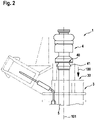
- the connecting region 40 has a first end 45 and a second end 46, the first end 45 being arranged in front of the second end 46 in the injection direction 100 ( figure 2 ).
- the first end 45 is an end on the rail side, with the second end 46 being an end on the combustion chamber side.
- the first end 45 faces the common rail 12 in a mounted state of the injection arrangement 1 in the internal combustion engine 10 , the second end 46 facing a combustion chamber 11 of the internal combustion engine 10 .
- a longitudinal axis of the injection arrangement 1 is denoted by the reference number 101 .
- the longitudinal axis 101 defines a longitudinal direction.
- connection area 40 is advantageously designed to be rotationally symmetrical.
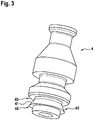
- the connection area 40 extends around the entire circumference of the connecting piece 4.
- connection area 40 has a collar 41 which extends radially outwards.
- the collar 41 particularly preferably spreads in the direction from the first end 45 to the second end 46.
- the collar 41 is designed in the shape of a truncated cone.
- the connecting portion 40 is located in front of a housing portion 30 in a direction corresponding to the direction from the first end 45 to the second end 46 . That is, the second end 46 of the connection portion 40 is in front of the housing portion 30 .
- the housing area 30 serves as the receiving area for receiving the holding element 9. The direction from the first end 45 to the second end 46 corresponds to the injection direction 100.
- the figure 4 shows a portion of an injection assembly 1 according to an example not according to the invention.
- connection area 40 has a groove 42 which engages with a shoulder 32 of the housing 3 .
- the shoulder 32 of the housing 3 and the groove 42 of the connection area 40 have complementary shapes.
- the shoulder 32 and the groove 42 have a rectangular profile in longitudinal section.
- other profiles are also possible.
- the groove 42 and the shoulder 32 are formed in a spiral shape.
- connection area 40 can have a plurality of grooves 42 which engage with a plurality of shoulders 32 of the housing 3 .
- the grooves 42 are arranged parallel to one another in the direction of the longitudinal axis 101 .
- each groove 42 runs around the entire circumference of the connecting piece 4.
- the shoulders 32 are arranged parallel to one another in the direction of the longitudinal axis 101.
- each shoulder 32 extends completely in the circumferential direction of the housing 3.
- the grooves 42 and the shoulders 32 can be ring-shaped.
- connection area 40 is located in front of the housing area 30 in the injection direction.
- the figure 5 shows a portion of an injection assembly 1 according to an example not according to the invention.
- connection portion 40 has a plurality of shoulders 43 which engage corresponding grooves 31 of the housing 3 .
- the shoulders 43 and the grooves 31 preferably have complementary shapes.
- the paragraphs 43 and the grooves 31 are annular and have a rectangular profile in longitudinal section.
- the paragraphs 43 are arranged parallel to one another in the longitudinal direction 101 .
- the grooves 31 are arranged parallel to one another in the longitudinal direction 101 .
- connection area 40 is arranged in front of the housing area 30 in the injection direction 100 .
- the injection arrangement 1 according to an in figure 6 shown example differs from the injection assembly 1 according to the example of FIG figure 5 in that the profile of the shoulders 43 and the grooves 31 is triangular.
- connection area 40 is located after the housing area 30 in the injection direction 100 . This means that the first end 45 of the connection area 40 is arranged after the housing area 30 in the injection direction 100 .
- the figure 7 shows a portion of an injection assembly 1 according to an example not according to the invention.
- connection area 40 is designed in the shape of a Christmas tree. This means that the connection area comprises a plurality of shoulders 43 each having a right-angled triangular profile in a longitudinal section. The hypotenuse of each right triangle is in front of the long vertical side in the direction from the first end 45 to the second end 46 .
- connection area 40 is located in the injection direction 100 after the housing area 30.
- connecting portion 40 in FIGS Figures 4 to 7 is shown in section, wherein the housing 3 is shown partially transparent.
- connection portion 40 may include any combination of the elements described above, depending on the application.
Landscapes
- Engineering & Computer Science (AREA)
- Chemical & Material Sciences (AREA)
- Combustion & Propulsion (AREA)
- Mechanical Engineering (AREA)
- General Engineering & Computer Science (AREA)
- Manufacturing & Machinery (AREA)
- Fuel-Injection Apparatus (AREA)
Description
- Die vorliegende Erfindung betrifft eine Einspritzanordnung mit einem Einspritzventil zum Einspritzen eines Fluids, insbesondere eine Kraftstoffeinspritzventil-Anordnung.
- Um das Einspritzventil an einen Bereich der Brennkraftmaschine, insbesondere an eine Railtasse eines Common Rails, anzuschließen, wird ein Anschlussstutzen verwendet, wobei eine benötigte Haltekraft zum Halten des Einspritzventils durch ein Halteelement bereitgestellt wird. Die Haltekraft des Halteelements wird entweder direkt auf ein Gehäuse, welches das Einspritzventil umgibt, oder auf eine auf das Gehäuse geschweißte Scheibe übertragen. Dabei kann sich das Gehäuse setzen, wodurch ein Abstand zwischen dem Einspritzventil und dem Bereich der Brennkraftmaschine größer wird, und das Halteelement seinen Arbeitsbereich verlässt. Dabei können im Gehäuse gefährliche Spannungen und Dehnungen auftreten, die zu Rissen führen können. Die Risse führen zu Undichtigkeit des Gehäuses gegenüber Feuchtigkeit. Ferner ist die Scheibe ein zusätzliches Bauteil, das zuerst positioniert und dann geschweißt werden muss.
- Aus der
DE 11 2013 000 955 T5 ist bereits eine Einspritzventilanordnung, insbesondere eine Kraftstoffeinspritzventil-Anordnung, bekannt, die ein Einspritzventil, ein Kunststoff-Gehäuse, das zumindest teilweise das Einspritzventil umgibt, und einen Anschlussstutzen, der ein umspritzter Teil des Einspritzventils ist, umfasst. Der Anschlussstutzen besitzt einen mittleren Bereich als Verbindungsbereich, der ein radial nach außen stehenden Ringbund aufweist und über den das Einspritzventil am Gehäuse formschlüssig angeordnet ist. Das Gehäuse ist dabei als Umspritzteil in Form einer Kunststoffumspritzung ausgebildet. - Die erfindungsgemäße Einspritzventilanordnung, die insbesondere als eine Kraftstoffeinspritzventil-Anordnung ausgebildet ist, weist den Vorteil eines einfachen und robusten Aufbaus auf. Dies wird erfindungsgemäß durch eine Einspritzventilanordnung erreicht, welche ein Einspritzventil, ein Gehäuse, das zumindest teilweise das Einspritzventil umgibt, und einen Anschlussstutzen umfasst. Dabei ist der Anschlussstutzen mit dem Einspritzventil verbunden und weist einen Verbindungsbereich auf, über den das Einspritzventil am Gehäuse formschlüssig angeordnet ist. Die formschlüssige Verbindung zwischen dem Einspritzventil und dem Gehäuse verhindert ein Setzen des Gehäuses. Insbesondere bei Temperaturänderungen verhindert die formschlüssige Verbindung eine Bewegung des Gehäuses während einer Ausdehnung oder Schrumpfung. Somit werden die Festigkeit des Gehäuses aufrechterhalten und Undichtigkeiten vermieden. Weiterhin gibt es nur ein Bauteil, nämlich den Anschlussstutzen, welcher als die Schnittstelle zum Bereich der Brennkraftmaschine, insbesondere zu der Railtasse, dient und gleichzeitig das Gehäuse abstützt. Dadurch werden ein zusätzliches Bauteil und ein zusätzlicher Prozess zum Positionieren dieses Bauteils in der Einspritzanordnung gespart. Außerdem ist das Herstellen eines derartigen Anschlussstutzens einfach und sehr kostengünstig. Vorzugsweise ist der Anschlussstutzen am Gehäuse geschweißt.
- Die Unteransprüche zeigen bevorzugte Weiterbildungen der Erfindung.
- Vorzugsweise weist der Verbindungsbereich einen radial nach außen ersteckenden Kragen auf.
- Der Verbindungsbereich weist ein erstes Ende und ein zweites Ende auf, wobei das erste Ende in Einspritzrichtung vor dem zweiten Ende angeordnet ist. Das erste Ende ist ein railseitiges Ende, wobei das zweite Ende ein brennraumseitiges Ende ist. Mit anderen Worten ist das erste Ende in einem montierten Zustand der Einspritzvorrichtung in einer Brennkraftmaschine einem Common Rail zugewandt, wobei das zweite Ende einem Brennraum der Brennkraftmaschine zugewandt ist.
- Besonders bevorzugt verbreitet sich der Kragen in Richtung vom ersten Ende zum zweiten Ende. Insbesondere ist der Kragen in der Form eines Kegelstumpfes ausgebildet.
- Das Gehäuse weist vorzugsweise einen Gehäusebereich auf, der eingerichtet ist, ein Halteelement zum Halten der Einspritzanordnung an einem Bauteil einer Brennkraftmaschine aufzunehmen. Dabei ist der Verbindungsbereich des Einspritzventils in unmittelbarer Nähe des Gehäusebereichs angeordnet. Insbesondere ist der Verbindungsbereich in einer Längsrichtung des Gehäuses vor oder nach dem Gehäusebereich bzw. oberhalb oder unterhalb des Gehäusebereichs angeordnet. Die Längsrichtung entspricht einer Längsachse des Gehäuses.
- Der Verbindungsbereich dient als eine Art Verhakung, die dafür sorgt, dass sich das Gehäuse nicht setzt.
- Der Verbindungsbereich ist in vorteilhafter Weise rotationssymmetrisch ausgebildet. Besonders bevorzugt erstreckt sich der Verbindungsbereich um einen kompletten Umfang des Anschlussstutzens. Alternativ kann vorzugsweise der Verbindungsbereich in Umfangsrichtung des Anschlussstutzens nur abschnittsweise ausgebildet sein.
- Der Anschlussstutzen ist vorzugsweise ein Drehteil.
- Vorzugsweise ist das Gehäuse als Umspritzteil ausgebildet.
- Nachfolgend wird ein Ausführungsbeispiel der Erfindung unter Bezugnahme auf die begleitende Zeichnung im Detail beschrieben, wobei in weiteren Beispielen gleiche bzw. funktional gleiche Bauteile Teile jeweils mit dem gleichen Bezugszeichen bezeichnet sind. In der Zeichnung ist:
- Figur 1
- eine schematische vereinfachte Ansicht einer Einspritzanordnung gemäß einem Ausführungsbeispiel der vorliegenden Erfindung, wobei die Einspritzanordnung in einer Brennkraftmaschine angeordnet ist,
- Figur 2
- eine schematische vereinfachte vergrößerte Darstellung eines Bereichs der in
Figur 1 gezeigten Einspritzanordnung, - Figur 3
- eine schematische vereinfachte perspektivische Ansicht eines Anschlussstutzens, der in der Einspritzanordnung von
Figur 1 vorgesehen ist. - Figur 4
- eine schematische vereinfachte Ansicht einer Einspritzanordnung gemäß einem nicht erfindungsgemäßen Beispiel,
- Figur 5
- eine schematische vereinfachte Ansicht einer Einspritzanordnung gemäß einem nicht erfindungsgemäßen Beispiel,
- Figur 6
- eine schematische vereinfachte Ansicht einer Einspritzanordnung gemäß einem nicht erfindungsgemäßen Beispiel, und
- Figur 7
- eine schematische vereinfachte Ansicht einer Einspritzanordnung gemäß einem nicht erfindungsgemäßen Beispiel.
- Nachfolgend wird in Bezug auf die
Figuren 1 bis 3 eine Einspritzanordnung 1 gemäß einem Ausführungsbeispiel der Erfindung im Detail beschrieben. - Die
Figur 1 zeigt eine Brennkraftmaschine 10, in der die Einspritzanordnung 1 angeordnet ist. Zum Halten der Einspritzanordnung 1 an der Brennkraftmaschine 10 bzw. in einer Bohrung der Brennkraftmaschine 10 ist ein Halteelement 9 vorgesehen. Die Einspritzanordnung 1 ist insbesondere an einem Verteiler 12 bzw. Common Rail der Brennkraftmaschine 10 angebracht. - Die Einspritzventilanordnung 1, die insbesondere als eine Kraftstoffeinspritzventil-Anordnung ausgebildet ist, umfasst ein Einspritzventil 2, ein Gehäuse 3 und einen Anschlussstutzen 4. Das Gehäuse 3 umgibt zumindest teilweise das Einspritzventil 2 und ist als Umspritzteil ausgebildet. Weiterhin ist der Anschlussstutzen 4 mit dem Einspritzventil 2 verbunden und weist einen Verbindungsbereich 40 auf, über den das Einspritzventil 2 am Gehäuse 3 formschlüssig angeordnet ist. In
Figuren 1 und2 ist das Gehäuse 3 zur besseren Übersicht transparent dargestellt. - Vorzugsweise ist das Einspritzventil 2 mit dem Anschlussstutzen 4 mittels eines als Rohr ausgebildeten Verlängerungselements 5 verbunden.
- Der Verbindungsbereich 40 weist ein erstes Ende 45 und ein zweites Ende 46 auf, wobei das erste Ende 45 in Einspritzrichtung 100 vor dem zweiten Ende 46 angeordnet ist (
Figur 2 ). Das erste Ende 45 ist ein railseitiges Ende, wobei das zweite Ende 46 ein brennraumseitiges Ende ist. Mit anderen Worten ist das erste Ende 45 in einem montierten Zustand der Einspritzanordnung 1 in der Brennkraftmaschine 10 dem Common Rail 12 zugewandt, wobei das zweite Ende 46 einem Brennraum 11 der Brennkraftmaschine 10 zugewandt ist. Eine Längsachse der Einspritzanordnung 1 ist mit dem Bezugszeichen 101 bezeichnet. Die Längsachse 101 definiert eine Längsrichtung. - Wie aus den
Figuren 2 und3 ersichtlich ist, ist der Verbindungsbereich 40 in vorteilhafter Weise rotationssymmetrisch ausgebildet. Dabei erstreckt sich der Verbindungsbereich 40 um einen kompletten Umfang des Anschlussstutzens 4. - In diesem Ausführungsbeispiel weist der Verbindungsbereich 40 einen radial nach außen ersteckenden Kragen 41 auf.
- Besonders bevorzugt verbreitet sich der Kragen 41 in Richtung vom ersten Ende 45 zum zweiten Ende 46. Insbesondere ist der Kragen 41 kegelstumpfförmig ausgebildet.
- Der Verbindungsbereich 40 ist in einer Richtung, die der Richtung vom ersten Ende 45 zum zweiten Ende 46 entspricht, vor einem Gehäusebereich 30 angeordnet. Das heißt, dass sich das zweite Ende 46 des Verbindungsbereichs 40 vor dem Gehäusebereich 30 befindet. Der Gehäusebereich 30 dient als der Aufnahmebereich zum Aufnehmen des Halteelements 9. Die Richtung vom ersten Ende 45 zum zweiten Ende 46 entspricht der Einspritzrichtung 100.
- Die
Figur 4 zeigt einen Bereich einer Einspritzanordnung 1 gemäß einem nicht erfindungsgemäßen Beispiel. - In diesem Beispiel weist der Verbindungsbereich 40 eine Nut 42 auf, die mit einem Absatz 32 des Gehäuses 3 in Eingriff steht. Der Absatz 32 des Gehäuses 3 und die Nut 42 des Verbindungsbereiches 40 weisen komplementäre Formen auf. Insbesondere weisen der Absatz 32 und die Nut 42 ein rechteckiges Profil im Längsschnitt auf. Andere Profile sind allerdings auch möglich. Ferner sind die Nut 42 und der Absatz 32 spiralförmig ausgebildet.
- Alternativ kann der Verbindungsbereich 40 eine Mehrzahl von Nuten 42 aufweisen, die mit einer Mehrzahl von Absätzen 32 des Gehäuses 3 in Eingriff stehen. Die Nuten 42 sind dabei in Richtung der Längsachse 101 parallel zueinander angeordnet. Ferner verläuft jede Nut 42 um den ganzen Umfang des Anschlussstutzens 4. Entsprechend sind die Absätze 32 in Richtung der Längsachse 101 parallel zueinander angeordnet. Des Weiteren erstreckt sich jeder Absatz 32 vollständig in Umfangrichtung des Gehäuses 3. Dabei können die Nuten 42 und die Absätze 32 ringförmig ausgebildet sein.
- Wie im ersten Ausführungsbeispiel befindet sich der Verbindungsbereich 40 in Einspritzrichtung vor dem Gehäusebereich 30 angeordnet.
- Die
Figur 5 zeigt einen Bereich einer Einspritzanordnung 1 gemäß einem nicht erfindungsgemäßen Beispiel. - In diesem Beispiel weist der Verbindungsbereich 40 eine Mehrzahl von Absätzen 43 auf, die mit entsprechenden Nuten 31 des Gehäuses 3 in Eingriff steht. Die Absätze 43 und die Nuten 31 haben vorzugsweise komplementäre Formen. Insbesondere sind die Absätze 43 und die Nuten 31 ringförmig ausgebildet und weisen ein rechtförmiges Profil im Längsschnitt auf. Die Absätze 43 sind in Längsrichtung 101 parallel zueinander angeordnet. Entsprechend sind die Nuten 31 in Längsrichtung 101 parallel zueinander angeordnet.
- Der Verbindungsbereich 40 ist in der Einspritzrichtung 100 vor dem Gehäusebereich 30 angeordnet.
- Die Einspritzanordnung 1 gemäß einem in
Figur 6 gezeigten Beispiel unterscheidet sich von der Einspritzanordnung 1 gemäß dem Beispiel derFigur 5 dadurch, dass das Profil der Absätze 43 und der Nuten 31 dreieckförmig ausgebildet ist. - Ferner befindet sich der Verbindungsbereich 40 in Einspritzrichtung 100 nach dem Gehäusebereich 30. Dies bedeutet, dass das erste Ende 45 des Verbindungsbereichs 40 in der Einspritzrichtung 100 nach dem Gehäusebereich 30 angeordnet ist.
- Die
Figur 7 zeigt einen Bereich einer Einspritzanordnung 1 gemäß einem nicht erfindungsgemäßen Beispiel. - In diesem Beispiel ist der Verbindungsbereich 40 tannenbaumförmig ausgestaltet. Dies bedeutet, dass der Verbindungsbereich eine Mehrzahl von Absätzen 43 umfasst, die jeweils in einem Längsschnitt ein Profil eines rechtwinkligen Dreiecks aufweisen. Dabei befindet sich die Hypotenuse jedes rechtwinkligen Dreiecks in Richtung vom ersten Ende 45 zum zweiten Ende 46 vor der langen senkrechten Seite.
- Weiterhin befindet sich der Verbindungsbereich 40 in der Einspritzrichtung 100 nach dem Gehäusebereich 30.
- Es sei angemerkt, dass der Verbindungsbereich 40 in den
Figuren 4 bis 7 im Schnitt dargestellt ist, wobei das Gehäuse 3 zum Teil transparent dargestellt ist. - Es sei ferner angemerkt, dass je nach Anwendung der Verbindungsbereich 40 eine beliebige Kombination der oben beschriebenen Elemente aufweisen kann.
Claims (2)
- Einspritzventilanordnung, insbesondere Kraftstoffeinspritzventil-Anordnung, umfassend:- ein Einspritzventil (2),- ein Gehäuse (3), das zumindest teilweise das Einspritzventil (2) umgibt, und- einen Anschlussstutzen (4), der mit dem Einspritzventil (2) verbunden ist, und einen Verbindungsbereich (40) aufweist, über den das Einspritzventil (2) am Gehäuse (3) formschlüssig angeordnet ist,wobei das Gehäuse (3) als Umspritzteil ausgebildet ist,dadurch gekennzeichnet,dass der Anschlussstutzen (4) mit einem als Rohr ausgebildeten und zu einem railseitigen Ende ragenden Verlängerungselement (5) des Einspritzventils (2) verbunden ist und der Verbindungsbereich (40) an einem brennraumseitigen, dem Verlängerungselement (5) zugewandten Ende ausgebildet ist, wobei der Verbindungsbereich (40) wiederum ein erstes Ende (45) und ein zweites Ende (46) aufweist, wobei der Verbindungsbereich (40) am ersten Ende (45) mit einer Nut beginnt, an die sich ein radial nach außen ersteckender Kragen (41) anschließt, der sich in Richtung vom ersten Ende (45) zum zweiten Ende (46) verbreitet und kegelstumpfförmig ausgebildet ist, und wobei der Verbindungsbereich (40) am zweiten Ende (46) mit einem gegenüber dem Kragen (41) kleineren Durchmesser endet.
- Einspritzventilanordnung nach Anspruch 1, dadurch gekennzeichnet, dass das Gehäuse (3) einen Gehäusebereich (30) aufweist, der eingerichtet ist, ein Halteelement (9) zum Halten der Einspritzventilanordnung (1) an einem Bauteil einer Brennkraftmaschine (10) aufzunehmen, wobei der Verbindungsbereich (40) des Anschlussstutzens (4) in einer Längsrichtung (101) vor oder nach dem Gehäusebereich (30) angeordnet ist.
Applications Claiming Priority (2)
| Application Number | Priority Date | Filing Date | Title |
|---|---|---|---|
| DE102017214980.9A DE102017214980A1 (de) | 2017-08-28 | 2017-08-28 | Einspritzventilanordnung |
| PCT/EP2018/067542 WO2019042627A1 (de) | 2017-08-28 | 2018-06-29 | Einspritzventilanordnung |
Publications (2)
| Publication Number | Publication Date |
|---|---|
| EP3676489A1 EP3676489A1 (de) | 2020-07-08 |
| EP3676489B1 true EP3676489B1 (de) | 2022-08-10 |
Family
ID=62784167
Family Applications (1)
| Application Number | Title | Priority Date | Filing Date |
|---|---|---|---|
| EP18735287.7A Active EP3676489B1 (de) | 2017-08-28 | 2018-06-29 | Einspritzventilanordnung |
Country Status (7)
| Country | Link |
|---|---|
| US (1) | US20200224624A1 (de) |
| EP (1) | EP3676489B1 (de) |
| JP (1) | JP6900573B2 (de) |
| KR (1) | KR20200041890A (de) |
| CN (1) | CN111051680A (de) |
| DE (1) | DE102017214980A1 (de) |
| WO (1) | WO2019042627A1 (de) |
Family Cites Families (15)
| Publication number | Priority date | Publication date | Assignee | Title |
|---|---|---|---|---|
| DE3733604A1 (de) * | 1987-10-05 | 1989-04-13 | Bosch Gmbh Robert | Lochkoerper fuer eine kraftstoffeinspritzventil |
| DE19647586A1 (de) * | 1996-11-18 | 1998-05-20 | Bosch Gmbh Robert | Verteilereinrichtung für Brennstoffeinspritzanlagen |
| DE19758817B4 (de) * | 1997-12-17 | 2010-08-26 | Dr. Ing. H.C. F. Porsche Aktiengesellschaft | Halterung für ein Brennstoffeinspritzventil am Zylinderkopf einer Brennkraftmaschine |
| JP2004340208A (ja) * | 2003-05-14 | 2004-12-02 | Isuzu Motors Ltd | 配管接続構造 |
| DE102004048401A1 (de) * | 2004-10-01 | 2006-04-06 | Robert Bosch Gmbh | Niederhalter für eine Brennstoffeinspritzvorrichtung und Brennstoffeinspritzvorrichtung |
| DE502006006106D1 (de) * | 2005-03-03 | 2010-03-25 | Bosch Gmbh Robert | Brennstoffeinspritzvorrichtung |
| DE102005024053A1 (de) * | 2005-05-25 | 2006-11-30 | Robert Bosch Gmbh | Anschluss-System |
| DE102005061424A1 (de) * | 2005-12-22 | 2007-07-05 | Robert Bosch Gmbh | Brennstoffeinspritzventil |
| DE102005061408A1 (de) * | 2005-12-22 | 2007-06-28 | Robert Bosch Gmbh | Kunststoff-Metall-Verbindung und Brennstoffeinspritzventil mit einer Kraftstoff-Metall-Verbindung |
| US7406946B1 (en) * | 2007-04-02 | 2008-08-05 | Hitachi, Ltd. | Method and apparatus for attenuating fuel pump noise in a direct injection internal combustion chamber |
| DE102009028473A1 (de) * | 2009-08-12 | 2011-02-17 | Robert Bosch Gmbh | Steckverbindung |
| DE102010031277A1 (de) * | 2010-07-13 | 2012-01-19 | Robert Bosch Gmbh | Kraftstoffeinspritzventil mit reduzierter Bauteileanzahl |
| JP5819213B2 (ja) * | 2012-02-13 | 2015-11-18 | 株式会社ケーヒン | 電磁式燃料噴射弁 |
| DE102012206241A1 (de) * | 2012-04-17 | 2013-10-17 | Robert Bosch Gmbh | Vorrichtung zum Niederhalten eines Ventils zum Zumessen von Kraftstoff |
| EP2941559B1 (de) * | 2014-03-14 | 2017-04-12 | Continental Automotive GmbH | Kraftstoffeinspritzanordnung |
-
2017
- 2017-08-28 DE DE102017214980.9A patent/DE102017214980A1/de active Pending
-
2018
- 2018-06-29 EP EP18735287.7A patent/EP3676489B1/de active Active
- 2018-06-29 KR KR1020207005757A patent/KR20200041890A/ko not_active Withdrawn
- 2018-06-29 JP JP2020511954A patent/JP6900573B2/ja active Active
- 2018-06-29 WO PCT/EP2018/067542 patent/WO2019042627A1/de not_active Ceased
- 2018-06-29 US US16/641,866 patent/US20200224624A1/en not_active Abandoned
- 2018-06-29 CN CN201880056221.7A patent/CN111051680A/zh active Pending
Also Published As
| Publication number | Publication date |
|---|---|
| US20200224624A1 (en) | 2020-07-16 |
| EP3676489A1 (de) | 2020-07-08 |
| DE102017214980A1 (de) | 2019-02-28 |
| JP6900573B2 (ja) | 2021-07-07 |
| WO2019042627A1 (de) | 2019-03-07 |
| CN111051680A (zh) | 2020-04-21 |
| JP2020531745A (ja) | 2020-11-05 |
| KR20200041890A (ko) | 2020-04-22 |
Similar Documents
| Publication | Publication Date | Title |
|---|---|---|
| EP1117925B1 (de) | Kraftstoffhochdruckspeicher | |
| DE102005011958B3 (de) | Klemmfitting für ein Heizungs- und/oder Sanitärrohr | |
| EP3004702B1 (de) | Kombination aus einem gehäuse und einem ventil | |
| WO2013113314A1 (de) | Kraftstoffverteilerleiste | |
| EP2321521A1 (de) | Kraftstoffeinspritzventil zur anordnung an einem brennraum einer brennkraftmaschine | |
| EP2726730B1 (de) | Einspritzventil sowie verfahren zur herstellung eines einspritzventils | |
| EP3245433B1 (de) | Verbindungsanordnung zum ausbilden einer hydraulischen verbindung | |
| EP3276155B1 (de) | Kraftstoffeinspritzanlage für eine brennkraftmaschine | |
| AT501851B1 (de) | Verbindung von leitungen für hochdruckmedien | |
| DE102015205938A1 (de) | Bremsgerät mit einem Arbeitsflüssigkeitsbehälter | |
| EP3662156B1 (de) | Brennstoffeinspritzventil | |
| DE102012019043B4 (de) | Kugelgelenk und Verfahren zur Herstellung eines Kugelgelenks | |
| EP2592260B1 (de) | Kraftstoffinjektor, Verfahren zur Montage eines Kraftstoffinjektors sowie Spanneinrichtung zur Montage eines Kraftstoffinjektors | |
| EP1564472B1 (de) | Schlauchkupplung | |
| DE102017214980A1 (de) | Einspritzventilanordnung | |
| DE102022002430A1 (de) | Verbindungseinheit mit Lösesicherung, mit dieser Einheit ausgestattete Montagekomponente sowie deren Montageverfahren | |
| DE102012012422B4 (de) | Befestigungsanordnung einer Kraftstoffleitung an einem Injektor | |
| DE102011052907A1 (de) | Hochdruckfeste Anschlussverbindung, insbesondere in Kraftstoff-Einspritzsystemen | |
| DE102014213729A1 (de) | Anschlussstutzen sowie Hochdruckpumpe mit Anschlussstutzen | |
| EP3647624A1 (de) | Stellglied | |
| DE102017207207A1 (de) | Kraftstoffpumpe | |
| DE102014207586A1 (de) | Anschlussstutzen für eine Hochdruckpumpe in einem Kraftstoffeinspritzsystem sowie Hochdruckpumpe mit einem solchen Anschlussstutzen | |
| DE102020213354A1 (de) | Brennstoffeinspritzventil | |
| EP3147493A1 (de) | Brennstoffeinspritzvorrichtung | |
| EP3159530B1 (de) | Düsenbaugruppe für ein brennstoffeinspritzventil zum einspritzen eines gasförmigen und/oder flüssigen brennstoffs, brennstoffeinspritzventil |
Legal Events
| Date | Code | Title | Description |
|---|---|---|---|
| STAA | Information on the status of an ep patent application or granted ep patent |
Free format text: STATUS: UNKNOWN |
|
| STAA | Information on the status of an ep patent application or granted ep patent |
Free format text: STATUS: THE INTERNATIONAL PUBLICATION HAS BEEN MADE |
|
| PUAI | Public reference made under article 153(3) epc to a published international application that has entered the european phase |
Free format text: ORIGINAL CODE: 0009012 |
|
| STAA | Information on the status of an ep patent application or granted ep patent |
Free format text: STATUS: REQUEST FOR EXAMINATION WAS MADE |
|
| 17P | Request for examination filed |
Effective date: 20200330 |
|
| AK | Designated contracting states |
Kind code of ref document: A1 Designated state(s): AL AT BE BG CH CY CZ DE DK EE ES FI FR GB GR HR HU IE IS IT LI LT LU LV MC MK MT NL NO PL PT RO RS SE SI SK SM TR |
|
| STAA | Information on the status of an ep patent application or granted ep patent |
Free format text: STATUS: EXAMINATION IS IN PROGRESS |
|
| 17Q | First examination report despatched |
Effective date: 20210322 |
|
| GRAP | Despatch of communication of intention to grant a patent |
Free format text: ORIGINAL CODE: EPIDOSNIGR1 |
|
| STAA | Information on the status of an ep patent application or granted ep patent |
Free format text: STATUS: GRANT OF PATENT IS INTENDED |
|
| INTG | Intention to grant announced |
Effective date: 20220317 |
|
| GRAS | Grant fee paid |
Free format text: ORIGINAL CODE: EPIDOSNIGR3 |
|
| GRAA | (expected) grant |
Free format text: ORIGINAL CODE: 0009210 |
|
| STAA | Information on the status of an ep patent application or granted ep patent |
Free format text: STATUS: THE PATENT HAS BEEN GRANTED |
|
| AK | Designated contracting states |
Kind code of ref document: B1 Designated state(s): AL AT BE BG CH CY CZ DE DK EE ES FI FR GB GR HR HU IE IS IT LI LT LU LV MC MK MT NL NO PL PT RO RS SE SI SK SM TR |
|
| REG | Reference to a national code |
Ref country code: AT Ref legal event code: REF Ref document number: 1510721 Country of ref document: AT Kind code of ref document: T Effective date: 20220815 Ref country code: CH Ref legal event code: EP |
|
| REG | Reference to a national code |
Ref country code: IE Ref legal event code: FG4D Free format text: LANGUAGE OF EP DOCUMENT: GERMAN |
|
| REG | Reference to a national code |
Ref country code: DE Ref legal event code: R096 Ref document number: 502018010364 Country of ref document: DE |
|
| REG | Reference to a national code |
Ref country code: NL Ref legal event code: MP Effective date: 20220810 |
|
| REG | Reference to a national code |
Ref country code: LT Ref legal event code: MG9D |
|
| PG25 | Lapsed in a contracting state [announced via postgrant information from national office to epo] |
Ref country code: SE Free format text: LAPSE BECAUSE OF FAILURE TO SUBMIT A TRANSLATION OF THE DESCRIPTION OR TO PAY THE FEE WITHIN THE PRESCRIBED TIME-LIMIT Effective date: 20220810 Ref country code: RS Free format text: LAPSE BECAUSE OF FAILURE TO SUBMIT A TRANSLATION OF THE DESCRIPTION OR TO PAY THE FEE WITHIN THE PRESCRIBED TIME-LIMIT Effective date: 20220810 Ref country code: PT Free format text: LAPSE BECAUSE OF FAILURE TO SUBMIT A TRANSLATION OF THE DESCRIPTION OR TO PAY THE FEE WITHIN THE PRESCRIBED TIME-LIMIT Effective date: 20221212 Ref country code: NO Free format text: LAPSE BECAUSE OF FAILURE TO SUBMIT A TRANSLATION OF THE DESCRIPTION OR TO PAY THE FEE WITHIN THE PRESCRIBED TIME-LIMIT Effective date: 20221110 Ref country code: NL Free format text: LAPSE BECAUSE OF FAILURE TO SUBMIT A TRANSLATION OF THE DESCRIPTION OR TO PAY THE FEE WITHIN THE PRESCRIBED TIME-LIMIT Effective date: 20220810 Ref country code: LV Free format text: LAPSE BECAUSE OF FAILURE TO SUBMIT A TRANSLATION OF THE DESCRIPTION OR TO PAY THE FEE WITHIN THE PRESCRIBED TIME-LIMIT Effective date: 20220810 Ref country code: LT Free format text: LAPSE BECAUSE OF FAILURE TO SUBMIT A TRANSLATION OF THE DESCRIPTION OR TO PAY THE FEE WITHIN THE PRESCRIBED TIME-LIMIT Effective date: 20220810 Ref country code: FI Free format text: LAPSE BECAUSE OF FAILURE TO SUBMIT A TRANSLATION OF THE DESCRIPTION OR TO PAY THE FEE WITHIN THE PRESCRIBED TIME-LIMIT Effective date: 20220810 |
|
| PG25 | Lapsed in a contracting state [announced via postgrant information from national office to epo] |
Ref country code: PL Free format text: LAPSE BECAUSE OF FAILURE TO SUBMIT A TRANSLATION OF THE DESCRIPTION OR TO PAY THE FEE WITHIN THE PRESCRIBED TIME-LIMIT Effective date: 20220810 Ref country code: IS Free format text: LAPSE BECAUSE OF FAILURE TO SUBMIT A TRANSLATION OF THE DESCRIPTION OR TO PAY THE FEE WITHIN THE PRESCRIBED TIME-LIMIT Effective date: 20221210 Ref country code: HR Free format text: LAPSE BECAUSE OF FAILURE TO SUBMIT A TRANSLATION OF THE DESCRIPTION OR TO PAY THE FEE WITHIN THE PRESCRIBED TIME-LIMIT Effective date: 20220810 Ref country code: GR Free format text: LAPSE BECAUSE OF FAILURE TO SUBMIT A TRANSLATION OF THE DESCRIPTION OR TO PAY THE FEE WITHIN THE PRESCRIBED TIME-LIMIT Effective date: 20221111 |
|
| PG25 | Lapsed in a contracting state [announced via postgrant information from national office to epo] |
Ref country code: SM Free format text: LAPSE BECAUSE OF FAILURE TO SUBMIT A TRANSLATION OF THE DESCRIPTION OR TO PAY THE FEE WITHIN THE PRESCRIBED TIME-LIMIT Effective date: 20220810 Ref country code: RO Free format text: LAPSE BECAUSE OF FAILURE TO SUBMIT A TRANSLATION OF THE DESCRIPTION OR TO PAY THE FEE WITHIN THE PRESCRIBED TIME-LIMIT Effective date: 20220810 Ref country code: ES Free format text: LAPSE BECAUSE OF FAILURE TO SUBMIT A TRANSLATION OF THE DESCRIPTION OR TO PAY THE FEE WITHIN THE PRESCRIBED TIME-LIMIT Effective date: 20220810 Ref country code: DK Free format text: LAPSE BECAUSE OF FAILURE TO SUBMIT A TRANSLATION OF THE DESCRIPTION OR TO PAY THE FEE WITHIN THE PRESCRIBED TIME-LIMIT Effective date: 20220810 Ref country code: CZ Free format text: LAPSE BECAUSE OF FAILURE TO SUBMIT A TRANSLATION OF THE DESCRIPTION OR TO PAY THE FEE WITHIN THE PRESCRIBED TIME-LIMIT Effective date: 20220810 |
|
| REG | Reference to a national code |
Ref country code: DE Ref legal event code: R097 Ref document number: 502018010364 Country of ref document: DE |
|
| PG25 | Lapsed in a contracting state [announced via postgrant information from national office to epo] |
Ref country code: SK Free format text: LAPSE BECAUSE OF FAILURE TO SUBMIT A TRANSLATION OF THE DESCRIPTION OR TO PAY THE FEE WITHIN THE PRESCRIBED TIME-LIMIT Effective date: 20220810 Ref country code: EE Free format text: LAPSE BECAUSE OF FAILURE TO SUBMIT A TRANSLATION OF THE DESCRIPTION OR TO PAY THE FEE WITHIN THE PRESCRIBED TIME-LIMIT Effective date: 20220810 |
|
| PLBE | No opposition filed within time limit |
Free format text: ORIGINAL CODE: 0009261 |
|
| STAA | Information on the status of an ep patent application or granted ep patent |
Free format text: STATUS: NO OPPOSITION FILED WITHIN TIME LIMIT |
|
| PG25 | Lapsed in a contracting state [announced via postgrant information from national office to epo] |
Ref country code: AL Free format text: LAPSE BECAUSE OF FAILURE TO SUBMIT A TRANSLATION OF THE DESCRIPTION OR TO PAY THE FEE WITHIN THE PRESCRIBED TIME-LIMIT Effective date: 20220810 |
|
| 26N | No opposition filed |
Effective date: 20230511 |
|
| PG25 | Lapsed in a contracting state [announced via postgrant information from national office to epo] |
Ref country code: SI Free format text: LAPSE BECAUSE OF FAILURE TO SUBMIT A TRANSLATION OF THE DESCRIPTION OR TO PAY THE FEE WITHIN THE PRESCRIBED TIME-LIMIT Effective date: 20220810 |
|
| PG25 | Lapsed in a contracting state [announced via postgrant information from national office to epo] |
Ref country code: MC Free format text: LAPSE BECAUSE OF FAILURE TO SUBMIT A TRANSLATION OF THE DESCRIPTION OR TO PAY THE FEE WITHIN THE PRESCRIBED TIME-LIMIT Effective date: 20220810 |
|
| PG25 | Lapsed in a contracting state [announced via postgrant information from national office to epo] |
Ref country code: MC Free format text: LAPSE BECAUSE OF FAILURE TO SUBMIT A TRANSLATION OF THE DESCRIPTION OR TO PAY THE FEE WITHIN THE PRESCRIBED TIME-LIMIT Effective date: 20220810 |
|
| REG | Reference to a national code |
Ref country code: CH Ref legal event code: PL |
|
| REG | Reference to a national code |
Ref country code: BE Ref legal event code: MM Effective date: 20230630 |
|
| PG25 | Lapsed in a contracting state [announced via postgrant information from national office to epo] |
Ref country code: LU Free format text: LAPSE BECAUSE OF NON-PAYMENT OF DUE FEES Effective date: 20230629 |
|
| REG | Reference to a national code |
Ref country code: IE Ref legal event code: MM4A |
|
| PG25 | Lapsed in a contracting state [announced via postgrant information from national office to epo] |
Ref country code: LU Free format text: LAPSE BECAUSE OF NON-PAYMENT OF DUE FEES Effective date: 20230629 |
|
| PG25 | Lapsed in a contracting state [announced via postgrant information from national office to epo] |
Ref country code: IE Free format text: LAPSE BECAUSE OF NON-PAYMENT OF DUE FEES Effective date: 20230629 |
|
| PG25 | Lapsed in a contracting state [announced via postgrant information from national office to epo] |
Ref country code: IE Free format text: LAPSE BECAUSE OF NON-PAYMENT OF DUE FEES Effective date: 20230629 Ref country code: CH Free format text: LAPSE BECAUSE OF NON-PAYMENT OF DUE FEES Effective date: 20230630 |
|
| PG25 | Lapsed in a contracting state [announced via postgrant information from national office to epo] |
Ref country code: BE Free format text: LAPSE BECAUSE OF NON-PAYMENT OF DUE FEES Effective date: 20230630 |
|
| REG | Reference to a national code |
Ref country code: AT Ref legal event code: MM01 Ref document number: 1510721 Country of ref document: AT Kind code of ref document: T Effective date: 20230629 |
|
| PG25 | Lapsed in a contracting state [announced via postgrant information from national office to epo] |
Ref country code: AT Free format text: LAPSE BECAUSE OF NON-PAYMENT OF DUE FEES Effective date: 20230629 |
|
| PG25 | Lapsed in a contracting state [announced via postgrant information from national office to epo] |
Ref country code: AT Free format text: LAPSE BECAUSE OF NON-PAYMENT OF DUE FEES Effective date: 20230629 |
|
| PG25 | Lapsed in a contracting state [announced via postgrant information from national office to epo] |
Ref country code: BG Free format text: LAPSE BECAUSE OF FAILURE TO SUBMIT A TRANSLATION OF THE DESCRIPTION OR TO PAY THE FEE WITHIN THE PRESCRIBED TIME-LIMIT Effective date: 20220810 |
|
| PG25 | Lapsed in a contracting state [announced via postgrant information from national office to epo] |
Ref country code: BG Free format text: LAPSE BECAUSE OF FAILURE TO SUBMIT A TRANSLATION OF THE DESCRIPTION OR TO PAY THE FEE WITHIN THE PRESCRIBED TIME-LIMIT Effective date: 20220810 |
|
| PGFP | Annual fee paid to national office [announced via postgrant information from national office to epo] |
Ref country code: GB Payment date: 20250620 Year of fee payment: 8 |
|
| PGFP | Annual fee paid to national office [announced via postgrant information from national office to epo] |
Ref country code: FR Payment date: 20250627 Year of fee payment: 8 |
|
| PG25 | Lapsed in a contracting state [announced via postgrant information from national office to epo] |
Ref country code: CY Free format text: LAPSE BECAUSE OF FAILURE TO SUBMIT A TRANSLATION OF THE DESCRIPTION OR TO PAY THE FEE WITHIN THE PRESCRIBED TIME-LIMIT; INVALID AB INITIO Effective date: 20180629 |
|
| PG25 | Lapsed in a contracting state [announced via postgrant information from national office to epo] |
Ref country code: HU Free format text: LAPSE BECAUSE OF FAILURE TO SUBMIT A TRANSLATION OF THE DESCRIPTION OR TO PAY THE FEE WITHIN THE PRESCRIBED TIME-LIMIT; INVALID AB INITIO Effective date: 20180629 |
|
| PGFP | Annual fee paid to national office [announced via postgrant information from national office to epo] |
Ref country code: DE Payment date: 20250814 Year of fee payment: 8 |
|
| PGFP | Annual fee paid to national office [announced via postgrant information from national office to epo] |
Ref country code: IT Payment date: 20250630 Year of fee payment: 8 |
|
| PG25 | Lapsed in a contracting state [announced via postgrant information from national office to epo] |
Ref country code: TR Free format text: LAPSE BECAUSE OF FAILURE TO SUBMIT A TRANSLATION OF THE DESCRIPTION OR TO PAY THE FEE WITHIN THE PRESCRIBED TIME-LIMIT Effective date: 20220810 |