EP3676464B1 - Fastener for insulation material - Google Patents
Fastener for insulation material Download PDFInfo
- Publication number
- EP3676464B1 EP3676464B1 EP18759320.7A EP18759320A EP3676464B1 EP 3676464 B1 EP3676464 B1 EP 3676464B1 EP 18759320 A EP18759320 A EP 18759320A EP 3676464 B1 EP3676464 B1 EP 3676464B1
- Authority
- EP
- European Patent Office
- Prior art keywords
- fastener
- thread
- nut
- section
- tip
- Prior art date
- Legal status (The legal status is an assumption and is not a legal conclusion. Google has not performed a legal analysis and makes no representation as to the accuracy of the status listed.)
- Active
Links
- 239000012774 insulation material Substances 0.000 title description 2
- 238000000034 method Methods 0.000 claims description 17
- 238000009413 insulation Methods 0.000 claims description 10
- 238000009826 distribution Methods 0.000 claims description 8
- 229910052751 metal Inorganic materials 0.000 claims description 7
- 239000002184 metal Substances 0.000 claims description 7
- 239000004033 plastic Substances 0.000 claims description 7
- 229920003023 plastic Polymers 0.000 claims description 7
- 239000011324 bead Substances 0.000 claims description 5
- 238000005553 drilling Methods 0.000 claims description 4
- 238000004519 manufacturing process Methods 0.000 claims description 3
- 230000007704 transition Effects 0.000 claims description 3
- 239000011888 foil Substances 0.000 claims description 2
- 229910000831 Steel Inorganic materials 0.000 description 5
- 239000010959 steel Substances 0.000 description 5
- 230000000295 complement effect Effects 0.000 description 3
- 239000013039 cover film Substances 0.000 description 3
- 239000002023 wood Substances 0.000 description 3
- 238000004873 anchoring Methods 0.000 description 2
- 238000010276 construction Methods 0.000 description 2
- 238000001746 injection moulding Methods 0.000 description 2
- 239000000463 material Substances 0.000 description 2
- 239000012528 membrane Substances 0.000 description 2
- 230000000717 retained effect Effects 0.000 description 2
- 241001295925 Gegenes Species 0.000 description 1
- 229910052782 aluminium Inorganic materials 0.000 description 1
- XAGFODPZIPBFFR-UHFFFAOYSA-N aluminium Chemical compound [Al] XAGFODPZIPBFFR-UHFFFAOYSA-N 0.000 description 1
- 230000001276 controlling effect Effects 0.000 description 1
- 239000010408 film Substances 0.000 description 1
- 238000009434 installation Methods 0.000 description 1
- 230000035515 penetration Effects 0.000 description 1
- 239000002985 plastic film Substances 0.000 description 1
- 229920006255 plastic film Polymers 0.000 description 1
- 238000003825 pressing Methods 0.000 description 1
- 230000001105 regulatory effect Effects 0.000 description 1
- 239000000758 substrate Substances 0.000 description 1
Images

Classifications
-
- F—MECHANICAL ENGINEERING; LIGHTING; HEATING; WEAPONS; BLASTING
- F16—ENGINEERING ELEMENTS AND UNITS; GENERAL MEASURES FOR PRODUCING AND MAINTAINING EFFECTIVE FUNCTIONING OF MACHINES OR INSTALLATIONS; THERMAL INSULATION IN GENERAL
- F16B—DEVICES FOR FASTENING OR SECURING CONSTRUCTIONAL ELEMENTS OR MACHINE PARTS TOGETHER, e.g. NAILS, BOLTS, CIRCLIPS, CLAMPS, CLIPS OR WEDGES; JOINTS OR JOINTING
- F16B25/00—Screws that cut thread in the body into which they are screwed, e.g. wood screws
- F16B25/0036—Screws that cut thread in the body into which they are screwed, e.g. wood screws characterised by geometric details of the screw
- F16B25/0042—Screws that cut thread in the body into which they are screwed, e.g. wood screws characterised by geometric details of the screw characterised by the geometry of the thread, the thread being a ridge wrapped around the shaft of the screw
- F16B25/0057—Screws that cut thread in the body into which they are screwed, e.g. wood screws characterised by geometric details of the screw characterised by the geometry of the thread, the thread being a ridge wrapped around the shaft of the screw the screw having distinct axial zones, e.g. multiple axial thread sections with different pitch or thread cross-sections
- F16B25/0063—Screws that cut thread in the body into which they are screwed, e.g. wood screws characterised by geometric details of the screw characterised by the geometry of the thread, the thread being a ridge wrapped around the shaft of the screw the screw having distinct axial zones, e.g. multiple axial thread sections with different pitch or thread cross-sections with a non-threaded portion on the shaft of the screw
-
- E—FIXED CONSTRUCTIONS
- E04—BUILDING
- E04D—ROOF COVERINGS; SKY-LIGHTS; GUTTERS; ROOF-WORKING TOOLS
- E04D3/00—Roof covering by making use of flat or curved slabs or stiff sheets
- E04D3/36—Connecting; Fastening
- E04D3/3601—Connecting; Fastening of roof covering supported by the roof structure with interposition of a insulating layer
- E04D3/3603—Connecting; Fastening of roof covering supported by the roof structure with interposition of a insulating layer the fastening means being screws or nails
-
- F—MECHANICAL ENGINEERING; LIGHTING; HEATING; WEAPONS; BLASTING
- F16—ENGINEERING ELEMENTS AND UNITS; GENERAL MEASURES FOR PRODUCING AND MAINTAINING EFFECTIVE FUNCTIONING OF MACHINES OR INSTALLATIONS; THERMAL INSULATION IN GENERAL
- F16B—DEVICES FOR FASTENING OR SECURING CONSTRUCTIONAL ELEMENTS OR MACHINE PARTS TOGETHER, e.g. NAILS, BOLTS, CIRCLIPS, CLAMPS, CLIPS OR WEDGES; JOINTS OR JOINTING
- F16B25/00—Screws that cut thread in the body into which they are screwed, e.g. wood screws
- F16B25/001—Screws that cut thread in the body into which they are screwed, e.g. wood screws characterised by the material of the body into which the screw is screwed
- F16B25/0021—Screws that cut thread in the body into which they are screwed, e.g. wood screws characterised by the material of the body into which the screw is screwed the material being metal, e.g. sheet-metal or aluminium
-
- F—MECHANICAL ENGINEERING; LIGHTING; HEATING; WEAPONS; BLASTING
- F16—ENGINEERING ELEMENTS AND UNITS; GENERAL MEASURES FOR PRODUCING AND MAINTAINING EFFECTIVE FUNCTIONING OF MACHINES OR INSTALLATIONS; THERMAL INSULATION IN GENERAL
- F16B—DEVICES FOR FASTENING OR SECURING CONSTRUCTIONAL ELEMENTS OR MACHINE PARTS TOGETHER, e.g. NAILS, BOLTS, CIRCLIPS, CLAMPS, CLIPS OR WEDGES; JOINTS OR JOINTING
- F16B25/00—Screws that cut thread in the body into which they are screwed, e.g. wood screws
- F16B25/10—Screws performing an additional function to thread-forming, e.g. drill screws or self-piercing screws
- F16B25/103—Screws performing an additional function to thread-forming, e.g. drill screws or self-piercing screws by means of a drilling screw-point, i.e. with a cutting and material removing action
-
- F—MECHANICAL ENGINEERING; LIGHTING; HEATING; WEAPONS; BLASTING
- F16—ENGINEERING ELEMENTS AND UNITS; GENERAL MEASURES FOR PRODUCING AND MAINTAINING EFFECTIVE FUNCTIONING OF MACHINES OR INSTALLATIONS; THERMAL INSULATION IN GENERAL
- F16B—DEVICES FOR FASTENING OR SECURING CONSTRUCTIONAL ELEMENTS OR MACHINE PARTS TOGETHER, e.g. NAILS, BOLTS, CIRCLIPS, CLAMPS, CLIPS OR WEDGES; JOINTS OR JOINTING
- F16B25/00—Screws that cut thread in the body into which they are screwed, e.g. wood screws
Definitions
- the present invention is concerned with a fastening arrangement, in particular for securing insulation layers on roofs, a fastener particularly suitable for this, and an assembly method for this.
- the cover layer over the insulation layers usually consists of a roofing membrane or plastic film, and the substructure often consists of trapezoidal sheets. It is known to use a combination of screw and grommet for fastening.
- a spout is usually understood here to be a tubular sleeve with a constriction at one end and a radially protruding head widening at the other. This head extension is in the form of an oversized washer that rests on the roofing membrane when installed and distributes the tensile loads of the fastener over a large area.
- the inner diameter of the shank of the grommet is dimensioned so that the fastener and its head can be inserted into the grommet - the grommet also acts as an extension of the fastener.
- the fastener in the grommet is drilled through the insulation layers into the substructure.
- the head of the fastener hits the tip constriction of the grommet during the screwing-in process and, depending on the depth of the fastener, creates a tensile load on the grommet.
- the tensile loads can be controlled by turning the fastener back, but real regulation independent of the anchoring does not allow this.
- the EP 2 366 843 therefore suggests to complement the combination of grommet and fastener with a hex nut on the thread of the fastener.
- the external shape of the hexagon nut corresponds to the geometry of the interior of the socket shaft.
- the nut is therefore longitudinally displaceable along the spout axis, but the rotation of the nut and spout is bound.
- This allows the fastener to be anchored at the intended setting depth and then, by turning the grommet, the anchoring depth of the grommet can be regulated.
- the disadvantage here is that the head widening of the grommet exerts an undesirable (rotary) entrainment movement on the film, especially in the final assembly phase.
- the document DE 10 2009 051 081 A1 shows a special wrench screw with a thread section close to the head which is designed as a machine thread and a wood thread section close to the tip.
- the machine thread has a slightly larger outside diameter so that a suitable nut can be screwed onto the machine thread via the wood thread section.
- the present invention has set itself the goal of improving the state of the art in such a way that the adjustability of the setting depth of the grommet is improved. This is achieved by a fastener according to claim 1 which is used in a fastening arrangement according to claim 12. A method for assembling such a fastening device is described in claim 18.
- the invention uses a specially designed fastener in combination with a grommet and nut.
- the basic structure of the fastener 10, 20 or 80 comprises a head 11, an adjoining shaft 12 and an adjoining tip 13, the shank 12 having a threaded section 15 near the tip 13 and a threaded section 17 near the head 11.
- a nut 50 is attached there.
- a stop 18 is arranged between the threaded sections (15 or 17).
- This stop 18 serves, as will be explained below, as a depth limiter when driving in the fastener 10, 20, 80. It is characteristic that the thread section 15 close to the tip is designed as a right-hand thread and the second thread section 17 as a left-hand thread or, technically equivalent, the thread section 15 as Left-hand thread and the second threaded section 17 as a right-hand thread.
- the nut 50 is preferably formed from plastic, alternatively as a sheet metal part or a deep-drawn part.
- the shaped sheet metal part or deep-drawn part can be produced as a sleeve-shaped body, one edge of the sheet metal used being modeled on a thread edge. Both the plastic and sheet metal design allows this component to be manufactured inexpensively by machine and facilitates assembly.
- the abovementioned stop 18 can be implemented as part of an annular bead 22, the side of which facing the tip 13 fulfills this function. It is also possible to design the stop 18 as part of a thread-free section 16, the outer diameter (core diameter) of which is made wider. Alternatively, the outlet of the second threaded section 17 pointing towards the tip 13 can also function as a stop take over. In other words, both the bead 22 and a thread-free section 16 provide a step, a radially projecting stop surface, on their side facing the tip 13. This stop only serves as a depth limit for the setting process in the substructure.
- a thread-free shaft area 21 is arranged between the first threaded section 15 and the stop 18.
- the sheet steel is pulled through the first threaded section up to the stop 18 and is held in a defined manner in the thread-free section 21 between the stop and the thread run-out. This prevents further penetration of the fastener into the subsurface and the fastener can rotate freely.
- the tip 13 of the fastener 10, 20, 80 it is advantageous to design the tip 13 of the fastener 10, 20, 80 as a drill tip that can sink itself into the material without pre-drilling.
- the pitch of the thread in the thread section 15 close to the tip can be selected to be different from the pitch in the thread section 17 close to the head.
- the gradient can be selected larger or smaller.
- the threaded section 17 (close to the head) of the fastener 80 is designed to be weakened at least in an area 82 where the nut 50 is arranged.
- weakened means that the thread has a lower thread height than in the remaining shank area with a thread.
- the thread When viewed in cross-section, the thread will change, for example, from an essentially triangular to a trapezoidal cross-section. Alternatively, the thread can be made smaller as a whole while maintaining the triangular cross-section.
- the nut 50 or the area 82 on which it is arranged is attached to the thread run-out of the threaded section 17 close to the head.
- at the thread run-out is meant: directly adjacent or overlapping the thread run-out or completely or partially covering it.
- the region 82 can be an under-head section.
- the area 82 is designed as a thread-free (under-head) section, which would correspond to a maximally weakened thread (thread height zero).
- the fastener 80 is used in a fastening arrangement.
- this additionally comprises a grommet 30, which can be represented as an essentially cylindrical sleeve with a head part 31, a hollow cylindrical shaft 32 and a conical tip 33.
- the spout follows the prior art, the conical tip 33 of the spout 30 having a passage opening 35, the diameter of which is smaller than the inner diameter of the cylindrical interior 36 of the shaft 32.
- the in the figures as D max and D min designated diameter are chosen so that D max > D min applies.
- the cylindrical interior 36 of the grommet 30 and the through opening 35 have a common central axis 41. D min is selected so that the tip 13 and shaft 12 of a fastener 10, 20, 80 can pass, but not the nut 50.
- transition area between the cylindrical through opening 35 and the cylindrical interior space 35 in the case of the spout forms a substantially radially symmetrical, flat or slightly conical stop surface 38.
- the head part 31 can be designed differently. It either has a flange-like shape 37 which is designed to form a holding surface for an attachable load distribution disk.
- This load distribution disc can be designed in different materials (aluminum, sheet steel, plastic) with different shapes (circular, oval, polygonal) and diameters, depending on the task.
- the head can have an integrally formed radial head widening 39. Both versions have their specific advantages, which result from the application profile.
- the nut 50 preferably has a cylindrical shape about a central axis of rotation 51 and has a force application 52 at one longitudinal end.
- the nut 50 is molded from plastic and, during manufacture, is injected directly onto the section 82 of the second threaded section 17.
- the fastener is placed in a corresponding mold of an injection molding machine and enclosed by the mold.
- the nut 50 can be designed as a shaped sheet metal part or a deep-drawn part, which is pushed or screwed onto a section of the second threaded section 17.
- a nut 50 made separately from plastic can of course also be pushed on or screwed on.
- the free inner thread diameter of the nut means the free passage, measured diametrically from thread tip to thread tip of the internal thread. In this way, a nut 50 can pass the thread section 15 close to the tip, as can the stop 18 in order to then be screwed onto the thread section 17 close to the head.
- the advantage of the method is therefore that the direction of rotation of the fastener 80 can be maintained during the entire setting process of the fastening arrangement.
- the different thread directions between the first and second thread sections 15, 17 allow this procedure.
- first threaded section 15 is designed as a right-hand thread and the second threaded section 17 is designed as a left-hand thread
- the direction of rotation when drilling is traditionally clockwise.
- first threaded section 15 is designed as a left-hand thread and the second threaded section 17 is designed as a right-hand thread
- the direction of rotation during assembly is opposite, that is, counterclockwise.
- the assembly principle as described above is retained - the direction of rotation of the setting tool is retained in both cases.
- the associated tool is essentially made in two parts. It comprises a central part with a cylindrical rod, at one end of which a tool head is attached which can interact with a force application 19 in the head 11 of the fastener 10 or 20 or 80.
- the tool further comprises a tubular sleeve which can be arranged coaxially around the cylindrical rod and which is shaped at one end so that it fits into the force application 52 of the nut 50.
- the outside diameter of the tubular sleeve is selected to be somewhat smaller than D max of the interior 36 of the grommet 30.
- the free inner diameter of the tubular sleeve is sufficient to enclose a fastener with a connected drive tool.
- the fastener While the fastener is being set, only the central rod is in engagement with the force application in the head of the fastener via the tool head. After the fastener has been set, the fastener continues to rotate empty. Then the sleeve can be pushed along the shaft into the grommet until it reaches the nut 50, which is still rotating on the fastener. The sleeve engages in the force application 52 of the mother and brakes it or holds it firmly. Due to the opposite thread on the second threaded portion 17 compared to the first threaded portion 15, the nut 50 moves in the direction of the substructure while the fastener continues to rotate moved deeper into the spout until it, as described above, strikes against the stop surface 38 of the spout.
- this procedure saves time because he can do the setting and adjustment process in one operation.
- the fastener As soon as the fastener has reached its setting depth, it can start the adjustment process without interrupting the drive movement or changing the direction of rotation by sliding the sleeve over it and controlling it in a targeted manner so that the grommet is set at the required depth.
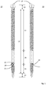
- FIG 1 a variant of a fastener is shown under the reference numerals 10 and 20 in each case. The difference is not in the function, but only in the technical design in one point.
- the main components in both cases are a head 11, an adjoining shaft 12 and a (drill) tip 13. Both variants have two threaded sections 15 and 17 on the shaft, one of which is a left-hand thread, the other a right-hand thread (or . vice versa).
- an unthreaded portion 16 is shown.
- the stop 18 is designed as a separate bead 22, in the variant 2 as a projection of a shaft section. Functionally, as described above, both perform the same service.
- the thread-free shank area 21 serves as a holding area for the support plate of the substructure as soon as the fastener has reached its end position.
- the force application 19 is only indicated as an internal engagement in the flange-like widening of the head 11.
- an external engagement eg as a square, hexagon
- a slim design is preferred in order to ensure the functionality as described above.
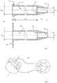
- a grommet 30 is shown in two variants. It consists essentially of a head (part) 31, a cylindrical or hollow-cylindrical shaft 32, which in turn is adjoined by a conically tapering tip 33.
- the free inner diameter D max of the head part 31 and shaft 32 is arranged coaxially around a common central axis 41 and is also (hollow) cylindrical and dimensioned so that the cylindrical interior 36 has a tool 60 with attached fasteners 10 or 20 plus the sleeve described above 63 can accommodate.
- the interior 36 merges into a cylindrical through opening 35, the transition forming a stop surface 38 facing the nozzle head 31.
- the upper variant of the nozzle 30 has a flange or a flange-like head 37.
- FIG. 4 It serves as an edge for holding a load distribution disc that is to be attached or can be attached.
- Figures 4 and 5 show such an attached load distribution disc in use.
- the variant in Figure 2 at the bottom is shown with a load distribution disk 39, which is an integral part of the grommet 30.
- This embodiment reduces the complexity of the system consisting of fasteners 10, 20 with nut 50, grommet 30 and attachable load distribution disc, but has the disadvantage of less flexibility in use.
- Figure 3 shows a nut 50 in an oblique view (left) and top view (right).
- a force application 52 is attached, which can interact with the tool 60 in the manner described above.
- three recesses offset by 120 ° are shown, into which complementary projections of the tool can engage.
- the central axis 51 then also forms the central axis of the tool 60 or the sleeve 63.
- This preferred embodiment is not restrictive; the person skilled in the art can interpret equivalent variants according to his specialist knowledge. In particular, variants with only one cutout, two cutouts (offset 180 °) or even 4 cutouts (offset 90 °) can be used. A spur toothing is also possible.
- the tools are designed to complement this.
- FIGs 4 and 5 show snapshots from the assembly process.
- the moment can be seen where the fastener 10, 20 has reached its installation depth and is turned over.
- the cylindrical rod 62 of the tool 60 is in engagement with the head of the fastener 10, 20 via the tool head 62.
- the nut 50 is on the second threaded section, but is not yet lowered.
- the grommet 30 has an attached load distribution disk.
- the insulation layer 71 still rests loosely on the support plate 72.
- FIG 5 shows the moment when the assembly is finished.
- the tubular sleeve is pushed over the cylindrical rod 61 of the tool 60 in such a way that the sleeve engages in the force applied by the nut 50.
- the sleeve 63 brakes the nut 50, whereby the latter begins to migrate in the direction of the fastener tip (downwards in the drawing).
- the grommet is pulled towards the support plate 72, which is in the Figure 5 is indicated as a slight deformation of the cover film 70.
- the tool 60 together with the sleeve can be pulled off and the next fastening arrangement can be set.
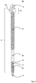
- Figure 6 shows a fastening arrangement made up of a fastener 80 and a nut 50.
- a head 11 is connected to a shaft 12 with a (drill) tip 13.
- a thread-free section 16 is arranged in between.
- the stop 18 as a depth limiter is shown as a separate bead, but is only meant to be exemplary and not restrictive.
- the thread-free shank area 21 serves as a holding area for the support plate of the substructure as soon as the fastener has reached its end position.
- Section 82 marks that area in which the nut 50 is advantageously arranged.
- the thread is weakened in this area or area 82 is produced as a thread-free under-head section.
Description
Die vorliegende Erfindung befasst sich mit einer Befestigungsanordnung, insbesondere zur Sicherung von Isolationsschichten auf Dächern, einem dafür besonders geeigneten Befestiger und einem Montageverfahren hierzu.The present invention is concerned with a fastening arrangement, in particular for securing insulation layers on roofs, a fastener particularly suitable for this, and an assembly method for this.
Um aktuellen Vorschriften zur Isolation von Flachdachkonstruktionen zu genügen, müssen je nach Klima auf einer tragenden Unterkonstruktion verschiedene Lagen von Isolationsmaterial rationell verarbeitet werden. Üblicherweise besteht die Abdecklage über den Isolationsschichten aus einer Dachbahn bzw. Kunststofffolie, die Unterkonstruktion häufig aus Trapezblechen. Zur Befestigung ist es bekannt, eine Kombination von Schraube und Tülle zu verwenden. Unter einer Tülle wird hierbei üblicherweise eine rohrförmige Hülse verstanden mit einer Verengung an einem Ende und einer radial abstehenden Kopfverbreiterung am anderen. Diese Kopfverbreiterung hat die Form einer überdimensionierten Unterlagscheibe, die im montierten Zustand auf der Dachbahn aufliegt und die Zuglasten des Befestigers flächig verteilt. Der Innendurchmesser des Schaftes der Tülle ist so bemessen, dass der Befestiger mitsamt Kopf in die Tülle eingeführt werden kann - die Tülle wirkt also auch als Verlängerung des Befestigers. Bei der Montage wird der Befestiger in der Tülle durch die Isolationsschichten in die Unterkonstruktion eingebohrt. Der Kopf des Befestigers schlägt beim Eindrehvorgang an der Spitzenverengung der Tülle an und sorgt je nach Setztiefe des Befestigers für eine Zuglast an der Tülle. Bei Unterkonstruktionen wie Holz oder Beton lassen sich u.U. durch Rückdrehen des Befestigers die Zuglasten kontrollieren, eine echte Regulierung unabhängig von der Verankerung erlaubt dies jedoch nicht.In order to meet current regulations for the insulation of flat roof constructions, different layers of insulation material have to be processed efficiently on a supporting substructure, depending on the climate. The cover layer over the insulation layers usually consists of a roofing membrane or plastic film, and the substructure often consists of trapezoidal sheets. It is known to use a combination of screw and grommet for fastening. A spout is usually understood here to be a tubular sleeve with a constriction at one end and a radially protruding head widening at the other. This head extension is in the form of an oversized washer that rests on the roofing membrane when installed and distributes the tensile loads of the fastener over a large area. The inner diameter of the shank of the grommet is dimensioned so that the fastener and its head can be inserted into the grommet - the grommet also acts as an extension of the fastener. During assembly, the fastener in the grommet is drilled through the insulation layers into the substructure. The head of the fastener hits the tip constriction of the grommet during the screwing-in process and, depending on the depth of the fastener, creates a tensile load on the grommet. In the case of substructures such as wood or concrete, the tensile loads can be controlled by turning the fastener back, but real regulation independent of the anchoring does not allow this.
Bei Blechunterkonstruktionen besteht darüber hinaus das Problem, dass der Eingriff des Befestigers im Untergrund (der Unterkonstruktion) sehr schmal ist und durch das Gewinde stark beansprucht wird. Eine Justage durch Vor- und Zurückdrehen des Befestigers kann die Auszugskräfte des Befestigers negativ beeinflussen.In the case of sheet metal substructures, there is also the problem that the engagement of the fastener in the subsurface (the substructure) is very narrow and is heavily stressed by the thread. Adjustment by turning the fastener forwards and backwards can negatively affect the pull-out force of the fastener.
Um bei der Befestigung von Isolationsschichten auf Stahlblechkonstruktionen die Justierbarkeit zu verbessern, schlägt die
Das Dokument
Die vorliegende Erfindung hat sich zum Ziel gesetzt, den Stand der Technik dahingehend zu verbessern, dass die Einstellbarkeit der Setztiefe der Tülle verbessert wird. Dies wird durch einen Befestiger gemäss Anspruch 1 erzielt, der in einer Befestigungsanordnung nach Anspruch 12 eingesetzt wird. Ein Verfahren zur Montage einer solchen Befestigungsvorrichtung ist in Anspruch 18 beschrieben.The present invention has set itself the goal of improving the state of the art in such a way that the adjustability of the setting depth of the grommet is improved. This is achieved by a fastener according to claim 1 which is used in a fastening arrangement according to
Die Erfindung verwendet einen speziell ausgeführten Befestiger in einer Kombination mit einer Tülle und einer Mutter.The invention uses a specially designed fastener in combination with a grommet and nut.
Dabei umfasst der Befestiger 10, 20 bzw. 80 in seinem Grundaufbau einen Kopf 11, einen anschliessenden Schaft 12 und eine daran anschliessenden Spitze 13, wobei der Schaft 12 einen Gewindeabschnitt 15 nahe der Spitze 13 und einen Gewindeabschnitt 17 nahe dem Kopf 11 aufweist. In der Ausführungsform des Befestigers 80 nach
Bevorzugt ist die Mutter 50 aus Kunststoff geformt, alternativ als Blechformteil oder Tiefziehteil. Das Blechformteil bzw. Tiefziehteil kann als hülsenförmiger Körper hergestellt werden, wobei eine Kante des verwendeten Bleches einer Gewindekante nachgebildet wird. Sowohl die Ausführung in Kunststoff wie Blech erlaubt eine maschinelle, kostengünstige Herstellung dieses Bauteils und erleichtert die Montage.The
Der vorerwähnte Anschlag 18 kann als Teil eines ringförmigen Wulstes 22 realisiert werden, dessen zur Spitze 13 gewandte Seite diese Funktion erfüllt. Ebenso möglich ist es, den Anschlag 18 als Teil eines gewindefreien Abschnittes 16 auszuführen, wobei dessen Aussendurchmesser (Kerndurchmesser) verbreitert ausgeführt ist. Alternativ kann auch der zur Spitze 13 weisende Auslauf des zweiten Gewindeabschnitts 17 die Funktion des Anschlags übernehmen. Mit anderen Worten, sowohl der Wulst 22 wie auch ein gewindefreier Abschnitt 16 stellen an ihrer der Spitze 13 zugewandten Seite eine Stufe, eine radial vorkragende Anschlagfläche zur Verfügung. Dieser Anschlag dient nur als Tiefenbegrenzung für den Setzvorgang in der Unterkonstruktion. Nachdem der kopfnahe Gewindeabschnitt 17 gegensinnig zum ersten Gewindeabschnitt 15 angelegt ist, greift das Gewinde im Abschnitt 17 nicht in das von der Spitze 13 dimensionierte Loch und stellt somit funktionell ebenfalls eine Tiefenbegrenzung dar. In
In einer weiteren Ausbildungsform wird zwischen dem ersten Gewindeabschnitt 15 und dem Anschlag 18 ein gewindefreier Schaftbereich 21 angeordnet. Beim Eindrehen des Befestigers in einen Stahlblechuntergrund wird das Stahlblech durch den erste Gewindeabschnitt bis zum Anschlag 18 gezogen und bleibt im gewindefreien Abschnitt 21 zwischen dem Anschlag und dem Gewindeauslauf definiert gehalten. Ein weiteres Eindringen des Befestigers in den Untergrund wird so verhindert, der Befestiger kann sich dabei frei drehen. Für den Einsatzbereich in Stahlblech ist es dabei vorteilhaft, die Spitze 13 des Befestigers 10, 20, 80 als Bohrspitze auszuführen, die sich ohne Vorbohren selbst in das Material einsenken kann.In a further embodiment, a thread-
In einer weiteren Ausführungsvariante kann die Steigung des Gewindes im spitzennahen Gewindeabschnitt 15 von der Steigung im kopfnahen Gewindeabschnitt 17 unterschiedlich gewählt werden. Je nach Auslegung kann die Steigung grösser oder kleiner gewählt werden.In a further embodiment variant, the pitch of the thread in the
In einer weiter bevorzugten Ausführungsvariante wird der (kopfnahe) Gewindeabschnitt 17 des Befestigers 80 mindestens in einem Bereich 82, wo die Mutter 50 angeordnet ist, geschwächt ausgeführt. Geschwächt bedeutet in diesem Zusammenhang, dass das Gewinde eine geringere Gewindehöhe aufweist als im restlichen Schaftbereich mit Gewinde. Im Querschnitt betrachtet wird sich das Gewinde beispielsweise von einem im Wesentlichen dreieckigen zu einem trapezoidalen Querschnitt verändern. Alternativ kann der Gewindegang als Ganzes verkleinert ausgeführt werden unter Beibehaltung des dreieckigen Querschnitts.In a further preferred embodiment variant, the threaded section 17 (close to the head) of the
In einer bevorzugten Varianten ist die Mutter 50 bzw. der Bereich 82 auf dem sie angeordnet ist, am kopfnahen Gewindeauslauf des Gewindeabschnitts 17 angebracht. Mit "am Gewindeauslauf" sei dabei gemeint: Unmittelbar benachbart bzw. den Gewindeauslauf überlappend bzw. ganz oder teilweise überdeckend. Insbesondere kann der Bereich 82 ein Unterkopfabschnitt sein. In einer besonders bevorzugten Variante ist der Bereich 82 als gewindefreier (Unterkopf-) Abschnitt ausgeführt, was einem maximal geschwächten Gewinde entspräche (Gewindehöhe Null).In a preferred variant, the
Wie vorerwähnt, kommt der Befestiger 80 in einer Befestigungsanordnung zum Einsatz. Diese umfasst neben dem Befestiger 80 zusätzlich eine Tülle 30, die als im wesentlichen zylindrische Hülse mit einem Kopfteil 31, einem hohlzylindrischem Schaft 32 und einer konischen Spitze 33 dargestellt werden kann. Die Tülle folgt in ihrer Grundform dem Stand der Technik, wobei die konische Spitze 33 der Tülle 30 über eine Durchtrittsöffnung 35 verfügt, deren Durchmesser geringer ist als der Innendurchmesser des zylindrischen Innenraums 36 des Schaftes 32. Die in den Figuren als Dmax und Dmin bezeichneten Durchmesser sind also so gewählt, dass gilt Dmax>Dmin. Der zylindrische Innenraum 36 der Tülle 30 und die Durchgangsöffnung 35 verfügen dabei über eine gemeinsame Zentralachse 41. Dmin ist so gewählt, dass Spitze 13 und Schaft 12 eines Befestigers 10, 20, 80 passieren können, nicht jedoch die Mutter 50.As previously mentioned, the
Dies deswegen, weil der Übergangsbereich zwischen der zylindrischen Durchgangsöffnung 35 und dem zylindrischen Innenraum 35 bei der Tülle eine im wesentlichen radialsymmetrische, ebene oder leicht konische Anschlagfläche 38 bildet.This is because the transition area between the cylindrical through opening 35 and the cylindrical
Bei der Tülle selbst wiederum kann das Kopfteil 31 unterschiedlich ausgeführt sein. Es weist entweder eine flanschähnliche Form 37 auf, die dazu ausgelegt ist, für eine aufsteckbare Lastverteilscheibe eine Haltefläche zu bilden. Diese Lastverteilscheibe kann aufgabenspezifisch in verschiedenen Materialien (Aluminium, Stahlblech, Kunststoff) ausgeführt sein mit unterschiedlichen Formen (kreisrund, oval, vieleckig) und Durchmessern. Alternativ kann der Kopf eine angeformte radiale Kopfverbreiterung 39 aufweisen. Beide Ausführungen haben ihre spezifischen Vorteile, die sich aus dem Einsatzprofil ergeben.In the case of the spout itself, in turn, the
Bezüglich der Mutter 50 gilt, dass sie bevorzugt eine zylindrische Form um eine zentrale Rotationsachse 51 hat und an einem Längsende einen Kraftangriff 52 aufweist. Durch das Einführen des Befestigers mit der Mutter in die Tülle 30 ist ein Kraftangriff radial aussen nicht sinnvoll. Daher wird er bevorzugt an die an das zylindrische Vorderende verlegt und weist somit im vormontierten Zustand von der Tüllenspitze 33 weg.With regard to the
In einer ersten bevorzugten Variante wird die Mutter 50 aus Kunststoff geformt und bei der Herstellung direkt auf den Abschnitt 82 des zweiten Gewindeabschnittes 17 aufgespritzt. Dazu wird der Befestiger in eine entsprechende Form einer Spritzgiessmaschine eingelegt und von der Form umschlossen. Vorteil ist, dass das erforderliche Gewinde der Mutter beim Spritzgiessvorgang entsteht und die Mutter zugleich korrekt ausgerichtet vormontiert ist. Alternativ kann die Mutter 50 als Blechformteil oder Tiefziehteil ausgeführt werden, das auf einen Abschnitt zweiten Gewindeabschnittes 17 aufgeschoben oder aufgeschraubt wird. Auch eine separat hergestellte Mutter 50 aus Kunststoff kann natürlich aufgeschoben bzw. aufgeschraubt werden.In a first preferred variant, the
Wegen der beiden gegenläufigen Gewinde 15 bzw. 17 ist ein Aufschieben bzw. Aufschrauben natürlich sinnvoll nur dann möglich, wenn das Gewinde der Mutter 50 passend zum Drehsinn des Gewindeabschnitts 17 ausgelegt ist. Daher werden am vorteilhaftesten die Aussendurchmesser des spitzennahe Gewindeabschnitts 15 wie auch des Anschlags 18 geringer gewählt als der freie Gewindeinnendurchmesser der Mutter 50. Mit freier Gewindeinnendurchmesser der Mutter ist dabei der freie Durchlass gemeint, diametral von Gewindespitze zu Gewindespitze des Innengewindes gemessen. Auf diese Weise kann eine Mutter 50 den spitzennahen Gewindeabschnitt 15 passieren, ebenso den Anschlag 18 um anschliessend auf den kopfnahen Gewindeabschnitt 17 aufgeschraubt zu werden.Because of the two opposing
Das Montageverfahren für den oben beschriebenen Befestiger bzw. die angesprochene Befestigungsvorrichtung kann mit folgenden Schritten beschrieben werden:
- Bereitstellen einer Befestigungsanordnung wie oben beschrieben, wobei der Befestiger 80
mit der Mutter 50 inden Innenraum 36der Tülle 30 eingeführt ist. Diese Vormontage kann ab Werk erfolgen oder auf der Baustelle vorgenommen werden. Sinnvoll ist, dieKombination von Befestiger 80mit Mutter 50 vormontiert zu haben und vor Ort, je nach Dicke der zu verarbeitenden Isolationsschichten mit einer Tülle passender Länge durch Einstecken zu kombinieren. - Eindrücken bzw. Eindrehen der Befestigungsanordnung in eine Gebäudehülle aus zumindest Abdeckfolie, Isolationsschicht und Tragblech (in Arbeitsrichtung betrachtet). Je nach Dicke und Zähigkeit kann dieses Eindrücken von Hand erfolgen. Die Spitze des Befestigers (Bohrspitze) reicht in der Regel aus, um die Kombination aus Befestiger und Tülle in Position zu bringen. Alternativ kann die Kombination auch auf ein Setzwerkzeug (Bohrmaschine mit Werkzeug) aufgesteckt werden und damit die Abdeckfolie und die Isolationsschicht mit motorischer Unterstützung durchdrungen werden.
- Im nächsten Schritt geht es um das Durchbohren des Tragbleches mit Hilfe der Bohrspitze, bis das
Tragblech am Anschlag 18 anschlägt und der Befestiger 80 überdreht. Nach dem Bohrvorgang zieht der ersteGewindeabschnitt 15 den Befestiger in das Tragblech bis es inden gewindefreien Schaftbereich 18 gelangt und dort zwischen dem letzten Gewindegang unddem Anschlag 18 gehalten wird. Sichern der Mutter 50 mittels eines Werkzeuges gegen die (Mit-)Drehbewegung des Befestigers, wodurch dieMutter 50 sich aufdem zweiten Gewindeabschnitt 17 desBefestigers 80 inRichtung Spitze 13 bewegt.- Nach dem
Anschlagen der Mutter 50 ander Anschlagfläche 38der Tülle 30 nimmt dieMutter 50 während der weiteren Drehbewegung des Befestigers 80 die Tülle mit und bewegt sie in Richtung Unterkonstruktion. Dabei dreht sich - im Gegensatz zum Stand der Technik - die Tülle selbst nicht zwangsläufig mit und vermeidet dadurch eine Belastung der Abdeckfolie. - Bei Erreichen der geforderten Setztiefe der Tülle 30 wird die Drehbewegung beendet.
- Providing a fastening arrangement as described above, wherein the
fastener 80 is inserted with thenut 50 into the interior 36 of thegrommet 30. This pre-assembly can be done at the factory or on the construction site. It makes sense to have the combination offastener 80 withnut 50 preassembled and, depending on the thickness of the insulation layers to be processed, to combine it with a grommet of the appropriate length by inserting it on site. - Pressing or screwing the fastening arrangement into a building shell made of at least a cover film, insulation layer and support plate (viewed in the working direction). Depending on the thickness and toughness, this can be done by hand. The tip of the fastener (drill bit) is usually sufficient to bring the combination of fastener and grommet into position. Alternatively, the combination can also be attached to a setting tool (drill with tool) and the cover foil and the insulation layer can be penetrated with motorized assistance.
- The next step is to drill through the support plate with the help of the drill bit until the support plate strikes the
stop 18 and thefastener 80 is turned over. After the drilling process, the first threadedsection 15 pulls the fastener into the support plate until it reaches the thread-free shank area 18 and is held there between the last thread turn and thestop 18. - Securing the
nut 50 by means of a tool against the (co-) rotating movement of the fastener, whereby thenut 50 moves on the second threadedsection 17 of thefastener 80 in the direction of thetip 13. - After the
nut 50 has hit thestop surface 38 of thegrommet 30, thenut 50 takes the grommet with it during the further rotary movement of thefastener 80 and moves it in the direction of the substructure. In contrast to the state of the art, the spout itself does not necessarily rotate with it, thereby avoiding stress on the cover film. - When the required setting depth of the
grommet 30 is reached, the rotary movement is ended.
Der Vorteil des Verfahrens besteht somit darin, dass während des gesamten Setzvorgangs der Befestigungsanordnung die Drehrichtung des Befestigers 80 beibehalten werden kann. Die unterschiedliche Gewinderichtung zwischen erstem und zweiten Gewindeabschnitt 15, 17 erlaubt diese Vorgehensweise.The advantage of the method is therefore that the direction of rotation of the
Wenn der erste Gewindeabschnitt 15 als Rechtsgewinde und der zweite Gewindeabschnitt 17 als Linksgewinde ausgeführt ist, ist die Drehrichtung beim Einbohren klassisch im Uhrzeigersinn. Wird der erste Gewindeabschnitt 15 als Linksgewinde und der zweite Gewindeabschnitt 17 als Rechtsgewinde ausgeführt, ist die Drehrichtung bei der Montage gegensinnig, also im Gegenuhrzeigersinn. Das Montageprinzip wie oben geschildert bleibt jedoch erhalten - die Drehrichtung des Setzgeräts wird in beiden Fällen beibehalten.If the first threaded
Um diese Einsatzweise zu erlauben, wird das zugehörige Werkzeug im Wesentlichen zweiteilig ausgeführt. Es umfasst einen zentralen Teil mit einer zylindrischen Stange, an deren einem Ende ein Werkzeugkopf angebracht ist, der mit einem Kraftangriff 19 im Kopf 11 des Befestigers 10 bzw. 20 oder 80 zusammenwirken kann. Ferner umfasst das Werkzeug eine rohrförmige Hülse, die koaxial um die zylindrische Stange angeordnet werden kann und die an ihrem einem Ende so geformt ist, dass sie in den Kraftangriff 52 der Mutter 50 passt. Der Aussendurchmesser der rohrförmigen Hülse wird etwas kleiner als Dmax des Innenraums 36 der Tülle 30 gewählt. Der freie Innendurchmesser der rohrförmigen Hülse ist ausreichend, um einen Befestiger mit verbundenem Antriebswerkzeug zum umschliessen.In order to allow this type of use, the associated tool is essentially made in two parts. It comprises a central part with a cylindrical rod, at one end of which a tool head is attached which can interact with a
Während der Setzung des Befestigers ist nur die zentrale Stange via Werkzeugkopf mit dem Kraftangriff im Kopf des Befestigers im Eingriff. Nach dem Setzen des Befestigers dreht der Befestiger leer weiter. Dann kann die Hülse am Schaft entlang in die Tülle geschoben werden, bis diese die (noch auf dem Befestiger) mitdrehende Mutter 50 erreicht. Die Hülse greift in den Kraftangriff 52 der Mutter ein und bremst sie ab bzw. hält sie fest. Durch das im Verglich zum ersten Gewindeabschnitt 15 gegensinnige Gewinde auf dem zweiten Gewindeabschnitt 17 wird bei beibehaltener Drehung des Befestigers die Mutter 50 in Richtung Unterkonstruktion tiefer in die Tülle bewegt, bis diese, wie vorbeschrieben, an der Anschlagfläche 38 der Tülle anschlägt.While the fastener is being set, only the central rod is in engagement with the force application in the head of the fastener via the tool head. After the fastener has been set, the fastener continues to rotate empty. Then the sleeve can be pushed along the shaft into the grommet until it reaches the
Für den Bediener bedeutet dieses Vorgehen eine Zeitersparnis, weil er den Setz- und Justiervorgang in einem Arbeitsgang erledigen kann. Sobald der Befestiger seine Setztiefe erreicht hat, kann er ohne die Antriebsbewegung zu unterbrechen oder die Drehrichtung zu ändern durch Überschieben der Hülse den Justiervorgang beginnen und gezielt so steuern, dass die Tülle in der geforderten Tiefe gesetzt wird.For the operator, this procedure saves time because he can do the setting and adjustment process in one operation. As soon as the fastener has reached its setting depth, it can start the adjustment process without interrupting the drive movement or changing the direction of rotation by sliding the sleeve over it and controlling it in a targeted manner so that the grommet is set at the required depth.
Die Erfindung wird nun mit Bezug auf die begleitenden Zeichnungen anhand besonders bevorzugter Ausführungsformen beispielhaft erläutert.
-
Figur 1 zeigt zwei Ausführungsvarianten eines Befestigers gemäss der Erfindung ohne Mutter -
Figur 2 zeigt zwei Varianten einer Tülle gemäss Erfindung -
Figur 3 zeigt perspektivisch und in axialer Draufsicht eine erfindungsgemässe Mutter -
Figur 4 bis 5 zeigen verschiedene Phase eines Setzvorgangs einer erfindungsgemässen Befestigungsanordnung. -
Figur 6 zeigt eine Befestigungsanordnung aus Befestiger und Mutter
-
Figure 1 shows two variants of a fastener according to the invention without a nut -
Figure 2 shows two variants of a grommet according to the invention -
Figure 3 shows a nut according to the invention in perspective and in an axial plan view -
Figures 4 to 5 show different phases of a setting process of a fastening arrangement according to the invention. -
Figure 6 Figure 3 shows a fastener and nut mounting arrangement
In
In
In
Die
In
Abschnitt 82 markiert jenen Bereich, in dem die Mutter 50 vorteilhafterweise angeordnet wird. Das Gewinde ist in diesem Bereich geschwächt ausgeführt bzw. Bereich 82 wird als gewindefreier Unterkopfabschnitt hergestellt.
Claims (19)
- A fastener (80), comprising a head (11), a shaft (12) connected thereto, and a tip (13) connected to said shaft, the shaft (12) having a thread section (17) close to the head (11), on which thread section a nut (50) is fitted, characterized in that the fastener has a further thread section (15) close to the tip (13) and a stop (18) arranged therebetween, wherein the thread section (15) closed to the tip is formed as a right-hand thread and the thread section (17) close to the head as a left-hand thread, or technically equivalent, the thread section (15) close to the tip is formed as a left-hand thread and the thread section (17) close to the head as a right-hand thread.
- The fastener (80) according to claim 1, characterized in that the nut (50) is molded from plastics or is formed as a sheet-metal molded part or deep-drawn part.
- The fastener (80) according to claim 1 and/or 2, characterized in that the stop (18) is formed as part of a ring-shaped bead (22) or as a section with an enlarged core diameter of a thread-free section (16) or is formed by the runout of the thread section (17) close to the head facing the tip (13).
- The fastener (80) according to any one of the preceding claims, characterized in that a thread-free shaft section (21) is arranged between the first (15) thread section and the stop (18).
- The fastener (80) according to any one of the preceding claims, characterized in that the tip (13) is formed as a drill tip.
- The fastener (80) according to any one of the preceding claims, characterized in that the pitch of the thread in the first thread section (15) is different from the pitch in the second thread section (17).
- The fastener (80) according to any one of the preceding claims, characterized in that the nut (50) has a cylindrical shape about a central axis of rotation (51) and, at one longitudinal end, has a force engagement means (52).
- The fastener (80) according to any one of the preceding claims, characterized in that the outer diameters of the thread section (15) close to the tip as well as of the stop (18) are smaller than the free inner thread diameter of the nut (50).
- The fastener (80) according to any one of the preceding claims, characterized in that the thread section (17) is formed to be weakened at least in a region (82) where the nut (50) is arranged.
- The fastener (80) according to any one of the preceding claims, characterized in that the nut (50) or the region (82) is arranged close to the runout of the thread close to the head of the thread section (17).
- The fastener (80) according to any one of the preceding claims, characterized in that the region (82) is formed as a thread-free section.
- A fastening arrangement, comprising- a grommet (30) formed as a substantially cylindrical sleeve having a head part (31), a hollow cylindrical shaft (32) and a conical tip (33),- a fastener (80) according to claims 1 to 11.
- The fastening arrangement according to claim 12, characterized in that the conical tip (33) of the grommet (30) has a passage opening (35) having a diameter that is smaller than the inner diameter of the cylindrical inner space (36) of the shaft (32), and in that the cylindrical inner space (36) and the passage opening (35) have a common central axis (41).
- The fastening arrangement according to claim 12 and/or 13, characterized in that the transition region between the cylindrical passage opening (35) and the cylindrical inner space (36) forms a substantially radially symmetrical, planar or slightly conical stop surface (38).
- The fastening arrangement according to claims 12 to 14, characterized in that the head (31) of the grommet (30)- either has a flange-shaped form (37) designed to form a holding surface for a load distribution disk (39),- or has an integral radial head widening.
- The fastening arrangement according to claims 12 to 15, characterized in that the nut (50), if molded from plastics, is injection-molded directly onto a section (82) of a thread section (17) close to the head during manufacture.
- The fastening arrangement according to claims 12 to 15, characterized in that during manufacture, the nut (50) is slid or screwed onto a section (82) of the thread section (17) close to the head.
- A method for mounting a fastening arrangement, comprising the following steps:- providing a fastening arrangement according to claims 12 to 16 or 12 to 15 and 17, wherein the fastener (80) with the nut (50) is introduced into the inner space (36) of the grommet (30),- pushing or screwing the fastening arrangement into a building envelope comprising at least a cover foil (70), an insulation layer (71) and a support sheet (72) (viewed in working direction),- drilling through the support sheet (72) with the aid of the drill tip until the support sheet (72) abuts against the stop (18) and the fastener (10, 20) overwinds,- securing the nut (50) by means of a tool against the rotational movement of the fastener, as a result of which the nut (50) moves on the second thread section (17) of the fastener (10) towards the tip (13),- abutting the nut (50) against the stop surface (38) of the grommet (30) and thereby driving the grommet by means of the nut (50) during the further rotational movement of the fastener (10),- ending the rotational movement upon reaching the placing depth of the grommet (30).
- The method according to claim 18, characterized in that the driving direction of the fastener (80) is maintained throughout the entire placement process of the fastening arrangement.
Priority Applications (1)
| Application Number | Priority Date | Filing Date | Title |
|---|---|---|---|
| PL18759320T PL3676464T3 (en) | 2017-09-01 | 2018-08-28 | Fastener for insulation material |
Applications Claiming Priority (2)
| Application Number | Priority Date | Filing Date | Title |
|---|---|---|---|
| EP17188934.8A EP3450647B1 (en) | 2017-09-01 | 2017-09-01 | Fastener for insulation material |
| PCT/EP2018/073080 WO2019042963A1 (en) | 2017-09-01 | 2018-08-28 | Fastener, fastening arrangement and method for mounting |
Publications (2)
| Publication Number | Publication Date |
|---|---|
| EP3676464A1 EP3676464A1 (en) | 2020-07-08 |
| EP3676464B1 true EP3676464B1 (en) | 2021-11-17 |
Family
ID=59829180
Family Applications (2)
| Application Number | Title | Priority Date | Filing Date |
|---|---|---|---|
| EP17188934.8A Active EP3450647B1 (en) | 2017-09-01 | 2017-09-01 | Fastener for insulation material |
| EP18759320.7A Active EP3676464B1 (en) | 2017-09-01 | 2018-08-28 | Fastener for insulation material |
Family Applications Before (1)
| Application Number | Title | Priority Date | Filing Date |
|---|---|---|---|
| EP17188934.8A Active EP3450647B1 (en) | 2017-09-01 | 2017-09-01 | Fastener for insulation material |
Country Status (7)
| Country | Link |
|---|---|
| US (1) | US11549542B2 (en) |
| EP (2) | EP3450647B1 (en) |
| DK (1) | DK3676464T3 (en) |
| ES (1) | ES2901461T3 (en) |
| PL (1) | PL3676464T3 (en) |
| PT (1) | PT3676464T (en) |
| WO (1) | WO2019042963A1 (en) |
Families Citing this family (1)
| Publication number | Priority date | Publication date | Assignee | Title |
|---|---|---|---|---|
| DE102020207059A1 (en) | 2020-06-05 | 2021-12-09 | Ejot Baubefestigungen Gmbh | Slope insulation screw for adjustable fastening of a roofing membrane on a sheet steel |
Family Cites Families (24)
| Publication number | Priority date | Publication date | Assignee | Title |
|---|---|---|---|---|
| US3682507A (en) * | 1970-06-02 | 1972-08-08 | Illinois Tool Works | Threaded fastener with stabilizing threads |
| US4781503A (en) * | 1983-06-22 | 1988-11-01 | Sfs Stadler Ag | Fastener assembly for securing roofing on a soft insulation material to a solid base |
| US4653244A (en) * | 1986-01-16 | 1987-03-31 | Farrell Mark A | Fastener element |
| GB8721048D0 (en) * | 1987-09-08 | 1987-10-14 | Itw Ltd | Screw threaded fastener |
| AT388409B (en) * | 1987-09-17 | 1989-06-26 | Sfs Stadler Ag | DEVICE FOR FASTENING ROOF COATINGS ON SOFT INSULATING MATERIAL ON A FIXED BASE |
| DE8908118U1 (en) * | 1989-04-22 | 1989-09-14 | Itw-Ateco Gmbh, 2000 Norderstedt, De | |
| JPH08232930A (en) | 1995-02-28 | 1996-09-10 | Nissei Kinzoku Kk | Coach screw |
| US5816012A (en) * | 1997-03-10 | 1998-10-06 | Alpine Engineered Products, Inc. | Dual threaded fastener and metal component assembly |
| EP0918164B1 (en) * | 1997-11-20 | 2003-07-09 | Meyer Liestal AG | Distance adjusting screw |
| DE19959672C2 (en) * | 1999-12-10 | 2002-04-18 | Sfs Ind Holding Ag Heerbrugg | Screw for fixing cover plates or rails to a substructure |
| JP2002054618A (en) * | 2000-08-10 | 2002-02-20 | Shinjo Seisakusho:Kk | Roof member installing screw, and method of manufacturing the same |
| US6666638B2 (en) * | 2001-02-15 | 2003-12-23 | Phillips Screw Company | Deck screw having multiple threaded sections |
| US20070059122A1 (en) * | 2005-09-09 | 2007-03-15 | Kwantex Research Inc. | Screw for composite board |
| US20070128001A1 (en) * | 2005-12-07 | 2007-06-07 | Guo-Cai Su | Screw with two types of threads |
| US7988396B2 (en) * | 2007-10-11 | 2011-08-02 | Handy & Harman | Deck screw |
| US8419332B2 (en) * | 2007-10-19 | 2013-04-16 | Atlas Bolt & Screw Company Llc | Non-dimpling fastener |
| US20110250035A1 (en) * | 2009-10-07 | 2011-10-13 | Moisture Management, Llc | Fastener assembly configured for attaching board in exterior wall |
| DE102009051081A1 (en) | 2009-10-28 | 2011-05-12 | Ehlert, Manfred | Lag bolt comprises machine thread, which is formed on shank between hexagon head and wooden thread, where diameter of machine thread is larger than diameter of wooden thread |
| US8672204B2 (en) * | 2010-01-13 | 2014-03-18 | National Nail Corp. | Fastener, installation tool and related method of use |
| NL2004410C2 (en) | 2010-03-16 | 2011-09-20 | Afast B V | Device and method for fastening insulating material. |
| CA2861647C (en) * | 2012-01-20 | 2016-05-24 | Handy & Harman | Screw for composite/plastic materials |
| US8926249B2 (en) * | 2013-04-19 | 2015-01-06 | Fushang Co., Ltd. | Screw |
| PL2930378T5 (en) * | 2014-04-11 | 2022-03-21 | Ejot Baubefestigungen Gmbh | Spacer fixing element |
| US20160186794A1 (en) * | 2014-12-30 | 2016-06-30 | Omg, Inc. | Trim Board Screw |
-
2017
- 2017-09-01 EP EP17188934.8A patent/EP3450647B1/en active Active
-
2018
- 2018-08-28 DK DK18759320.7T patent/DK3676464T3/en active
- 2018-08-28 WO PCT/EP2018/073080 patent/WO2019042963A1/en unknown
- 2018-08-28 US US16/643,178 patent/US11549542B2/en active Active
- 2018-08-28 ES ES18759320T patent/ES2901461T3/en active Active
- 2018-08-28 EP EP18759320.7A patent/EP3676464B1/en active Active
- 2018-08-28 PL PL18759320T patent/PL3676464T3/en unknown
- 2018-08-28 PT PT187593207T patent/PT3676464T/en unknown
Also Published As
| Publication number | Publication date |
|---|---|
| EP3450647A1 (en) | 2019-03-06 |
| WO2019042963A1 (en) | 2019-03-07 |
| PL3676464T3 (en) | 2022-03-21 |
| EP3676464A1 (en) | 2020-07-08 |
| EP3450647B1 (en) | 2021-08-11 |
| US11549542B2 (en) | 2023-01-10 |
| PT3676464T (en) | 2021-12-31 |
| DK3676464T3 (en) | 2022-02-21 |
| ES2901461T3 (en) | 2022-03-22 |
| US20200332823A1 (en) | 2020-10-22 |
Similar Documents
| Publication | Publication Date | Title |
|---|---|---|
| DE10126747C2 (en) | Blind rivet nut and fastening unit | |
| DE19644507C2 (en) | Screw and use of a screw for fastening profiles to a substructure | |
| EP2213888B1 (en) | Insulation holder | |
| DE3420863C3 (en) | Fasteners for fixing roofing membranes on soft insulating material on a solid surface | |
| AT13907U1 (en) | Fastening element and arrangement for fixing insulating panels | |
| EP2666919B1 (en) | Method and mounting system for attaching insulation panels to a support surface | |
| DE102012101320A1 (en) | Screw and thin sheet metal connection made therewith | |
| DE19846204C2 (en) | Fastening element and method for fastening insulation sheets or panels on a solid substructure, in particular in the roof area of buildings | |
| EP1582684A2 (en) | Screw for fixing hollow plastic section members with metal profiled reinforcements to a substructure | |
| DE19615191A1 (en) | Screw for fastening metal and / or plastic profiles or plates to a substructure | |
| EP2068007A2 (en) | Method and fixing system for attaching insulating boards, a dowel and a retainer | |
| DE102004064114B4 (en) | Fastening element for insulation boards | |
| DE10253888B4 (en) | fixing unit | |
| EP1175567B1 (en) | Fixing element for fixing insulating strips or plates on a solid substructure | |
| WO2009103391A1 (en) | Fastening element for wood-fibre insulating boards | |
| EP3676464B1 (en) | Fastener for insulation material | |
| EP2971400B1 (en) | Nozzle and fastening element for fastening a material layer | |
| EP3960963B1 (en) | Centring sleeve and method for fixing | |
| EP3421708B1 (en) | Multi-part adjustment set for separated assembly of a frame to a border | |
| DE102008058512A1 (en) | Insulation board attaching method for use in underground, involves moving retaining plate to end position with pressing of insulation boards relative to dowel during rotary motion of fastening unit, where movement of plate is limited | |
| DE19537000C1 (en) | Method for the adjustable fastening of slats, rails, plates or the like to a solid surface and fastening element for carrying out the method | |
| AT513720B1 (en) | fastener | |
| DE19645757C2 (en) | Screw connection | |
| EP4331760A1 (en) | Centering device, fixing arrangement and its use | |
| DE102015005691B4 (en) | Variable-length fastener |
Legal Events
| Date | Code | Title | Description |
|---|---|---|---|
| STAA | Information on the status of an ep patent application or granted ep patent |
Free format text: STATUS: UNKNOWN |
|
| STAA | Information on the status of an ep patent application or granted ep patent |
Free format text: STATUS: THE INTERNATIONAL PUBLICATION HAS BEEN MADE |
|
| PUAI | Public reference made under article 153(3) epc to a published international application that has entered the european phase |
Free format text: ORIGINAL CODE: 0009012 |
|
| STAA | Information on the status of an ep patent application or granted ep patent |
Free format text: STATUS: REQUEST FOR EXAMINATION WAS MADE |
|
| 17P | Request for examination filed |
Effective date: 20200401 |
|
| AK | Designated contracting states |
Kind code of ref document: A1 Designated state(s): AL AT BE BG CH CY CZ DE DK EE ES FI FR GB GR HR HU IE IS IT LI LT LU LV MC MK MT NL NO PL PT RO RS SE SI SK SM TR |
|
| AX | Request for extension of the european patent |
Extension state: BA ME |
|
| DAV | Request for validation of the european patent (deleted) | ||
| DAX | Request for extension of the european patent (deleted) | ||
| GRAP | Despatch of communication of intention to grant a patent |
Free format text: ORIGINAL CODE: EPIDOSNIGR1 |
|
| STAA | Information on the status of an ep patent application or granted ep patent |
Free format text: STATUS: GRANT OF PATENT IS INTENDED |
|
| INTG | Intention to grant announced |
Effective date: 20210617 |
|
| GRAS | Grant fee paid |
Free format text: ORIGINAL CODE: EPIDOSNIGR3 |
|
| GRAA | (expected) grant |
Free format text: ORIGINAL CODE: 0009210 |
|
| STAA | Information on the status of an ep patent application or granted ep patent |
Free format text: STATUS: THE PATENT HAS BEEN GRANTED |
|
| AK | Designated contracting states |
Kind code of ref document: B1 Designated state(s): AL AT BE BG CH CY CZ DE DK EE ES FI FR GB GR HR HU IE IS IT LI LT LU LV MC MK MT NL NO PL PT RO RS SE SI SK SM TR |
|
| REG | Reference to a national code |
Ref country code: GB Ref legal event code: FG4D Free format text: NOT ENGLISH |
|
| REG | Reference to a national code |
Ref country code: DE Ref legal event code: R096 Ref document number: 502018007907 Country of ref document: DE |
|
| REG | Reference to a national code |
Ref country code: IE Ref legal event code: FG4D Free format text: LANGUAGE OF EP DOCUMENT: GERMAN |
|
| REG | Reference to a national code |
Ref country code: AT Ref legal event code: REF Ref document number: 1448175 Country of ref document: AT Kind code of ref document: T Effective date: 20211215 |
|
| REG | Reference to a national code |
Ref country code: PT Ref legal event code: SC4A Ref document number: 3676464 Country of ref document: PT Date of ref document: 20211231 Kind code of ref document: T Free format text: AVAILABILITY OF NATIONAL TRANSLATION Effective date: 20211223 |
|
| REG | Reference to a national code |
Ref country code: NL Ref legal event code: FP |
|
| REG | Reference to a national code |
Ref country code: SE Ref legal event code: TRGR |
|
| REG | Reference to a national code |
Ref country code: FI Ref legal event code: FGE |
|
| REG | Reference to a national code |
Ref country code: EE Ref legal event code: FG4A Ref document number: E021828 Country of ref document: EE Effective date: 20211220 |
|
| REG | Reference to a national code |
Ref country code: DK Ref legal event code: T3 Effective date: 20220217 |
|
| REG | Reference to a national code |
Ref country code: LT Ref legal event code: MG9D |
|
| REG | Reference to a national code |
Ref country code: ES Ref legal event code: FG2A Ref document number: 2901461 Country of ref document: ES Kind code of ref document: T3 Effective date: 20220322 |
|
| REG | Reference to a national code |
Ref country code: NO Ref legal event code: T2 Effective date: 20211117 |
|
| RAP4 | Party data changed (patent owner data changed or rights of a patent transferred) |
Owner name: SFS GROUP INTERNATIONAL AG |
|
| PG25 | Lapsed in a contracting state [announced via postgrant information from national office to epo] |
Ref country code: RS Free format text: LAPSE BECAUSE OF FAILURE TO SUBMIT A TRANSLATION OF THE DESCRIPTION OR TO PAY THE FEE WITHIN THE PRESCRIBED TIME-LIMIT Effective date: 20211117 Ref country code: LT Free format text: LAPSE BECAUSE OF FAILURE TO SUBMIT A TRANSLATION OF THE DESCRIPTION OR TO PAY THE FEE WITHIN THE PRESCRIBED TIME-LIMIT Effective date: 20211117 Ref country code: BG Free format text: LAPSE BECAUSE OF FAILURE TO SUBMIT A TRANSLATION OF THE DESCRIPTION OR TO PAY THE FEE WITHIN THE PRESCRIBED TIME-LIMIT Effective date: 20220217 |
|
| PG25 | Lapsed in a contracting state [announced via postgrant information from national office to epo] |
Ref country code: IS Free format text: LAPSE BECAUSE OF FAILURE TO SUBMIT A TRANSLATION OF THE DESCRIPTION OR TO PAY THE FEE WITHIN THE PRESCRIBED TIME-LIMIT Effective date: 20220317 Ref country code: LV Free format text: LAPSE BECAUSE OF FAILURE TO SUBMIT A TRANSLATION OF THE DESCRIPTION OR TO PAY THE FEE WITHIN THE PRESCRIBED TIME-LIMIT Effective date: 20211117 Ref country code: HR Free format text: LAPSE BECAUSE OF FAILURE TO SUBMIT A TRANSLATION OF THE DESCRIPTION OR TO PAY THE FEE WITHIN THE PRESCRIBED TIME-LIMIT Effective date: 20211117 Ref country code: GR Free format text: LAPSE BECAUSE OF FAILURE TO SUBMIT A TRANSLATION OF THE DESCRIPTION OR TO PAY THE FEE WITHIN THE PRESCRIBED TIME-LIMIT Effective date: 20220218 |
|
| PG25 | Lapsed in a contracting state [announced via postgrant information from national office to epo] |
Ref country code: SM Free format text: LAPSE BECAUSE OF FAILURE TO SUBMIT A TRANSLATION OF THE DESCRIPTION OR TO PAY THE FEE WITHIN THE PRESCRIBED TIME-LIMIT Effective date: 20211117 Ref country code: SK Free format text: LAPSE BECAUSE OF FAILURE TO SUBMIT A TRANSLATION OF THE DESCRIPTION OR TO PAY THE FEE WITHIN THE PRESCRIBED TIME-LIMIT Effective date: 20211117 Ref country code: RO Free format text: LAPSE BECAUSE OF FAILURE TO SUBMIT A TRANSLATION OF THE DESCRIPTION OR TO PAY THE FEE WITHIN THE PRESCRIBED TIME-LIMIT Effective date: 20211117 |
|
| REG | Reference to a national code |
Ref country code: DE Ref legal event code: R097 Ref document number: 502018007907 Country of ref document: DE |
|
| PLBE | No opposition filed within time limit |
Free format text: ORIGINAL CODE: 0009261 |
|
| STAA | Information on the status of an ep patent application or granted ep patent |
Free format text: STATUS: NO OPPOSITION FILED WITHIN TIME LIMIT |
|
| 26N | No opposition filed |
Effective date: 20220818 |
|
| PG25 | Lapsed in a contracting state [announced via postgrant information from national office to epo] |
Ref country code: AL Free format text: LAPSE BECAUSE OF FAILURE TO SUBMIT A TRANSLATION OF THE DESCRIPTION OR TO PAY THE FEE WITHIN THE PRESCRIBED TIME-LIMIT Effective date: 20211117 |
|
| PG25 | Lapsed in a contracting state [announced via postgrant information from national office to epo] |
Ref country code: SI Free format text: LAPSE BECAUSE OF FAILURE TO SUBMIT A TRANSLATION OF THE DESCRIPTION OR TO PAY THE FEE WITHIN THE PRESCRIBED TIME-LIMIT Effective date: 20211117 |
|
| PGFP | Annual fee paid to national office [announced via postgrant information from national office to epo] |
Ref country code: CH Payment date: 20220901 Year of fee payment: 5 |
|
| PG25 | Lapsed in a contracting state [announced via postgrant information from national office to epo] |
Ref country code: MC Free format text: LAPSE BECAUSE OF FAILURE TO SUBMIT A TRANSLATION OF THE DESCRIPTION OR TO PAY THE FEE WITHIN THE PRESCRIBED TIME-LIMIT Effective date: 20211117 |
|
| PG25 | Lapsed in a contracting state [announced via postgrant information from national office to epo] |
Ref country code: LU Free format text: LAPSE BECAUSE OF NON-PAYMENT OF DUE FEES Effective date: 20220828 |
|
| P01 | Opt-out of the competence of the unified patent court (upc) registered |
Effective date: 20230622 |
|
| PGFP | Annual fee paid to national office [announced via postgrant information from national office to epo] |
Ref country code: NL Payment date: 20230823 Year of fee payment: 6 |
|
| PGFP | Annual fee paid to national office [announced via postgrant information from national office to epo] |
Ref country code: NO Payment date: 20230822 Year of fee payment: 6 Ref country code: IT Payment date: 20230831 Year of fee payment: 6 Ref country code: IE Payment date: 20230821 Year of fee payment: 6 Ref country code: GB Payment date: 20230824 Year of fee payment: 6 Ref country code: FI Payment date: 20230823 Year of fee payment: 6 Ref country code: ES Payment date: 20230918 Year of fee payment: 6 Ref country code: EE Payment date: 20230818 Year of fee payment: 6 Ref country code: CZ Payment date: 20230818 Year of fee payment: 6 Ref country code: AT Payment date: 20230818 Year of fee payment: 6 |
|
| PGFP | Annual fee paid to national office [announced via postgrant information from national office to epo] |
Ref country code: SE Payment date: 20230823 Year of fee payment: 6 Ref country code: PT Payment date: 20230821 Year of fee payment: 6 Ref country code: PL Payment date: 20230817 Year of fee payment: 6 Ref country code: FR Payment date: 20230821 Year of fee payment: 6 Ref country code: DK Payment date: 20230823 Year of fee payment: 6 Ref country code: DE Payment date: 20230822 Year of fee payment: 6 Ref country code: BE Payment date: 20230822 Year of fee payment: 6 |
|
| REG | Reference to a national code |
Ref country code: CH Ref legal event code: PL |