EP3676150B1 - Sitzeinheit und mobile einheit - Google Patents
Sitzeinheit und mobile einheit Download PDFInfo
- Publication number
- EP3676150B1 EP3676150B1 EP18793573.9A EP18793573A EP3676150B1 EP 3676150 B1 EP3676150 B1 EP 3676150B1 EP 18793573 A EP18793573 A EP 18793573A EP 3676150 B1 EP3676150 B1 EP 3676150B1
- Authority
- EP
- European Patent Office
- Prior art keywords
- seat
- elements
- supporting
- unit
- support arm
- Prior art date
- Legal status (The legal status is an assumption and is not a legal conclusion. Google has not performed a legal analysis and makes no representation as to the accuracy of the status listed.)
- Active
Links
Images


Classifications
-
- B—PERFORMING OPERATIONS; TRANSPORTING
- B61—RAILWAYS
- B61D—BODY DETAILS OR KINDS OF RAILWAY VEHICLES
- B61D33/00—Seats
- B61D33/0057—Seats characterised by their mounting in vehicles
- B61D33/0064—Seats characterised by their mounting in vehicles not adjustably mounted; supports therefor
-
- B—PERFORMING OPERATIONS; TRANSPORTING
- B60—VEHICLES IN GENERAL
- B60N—SEATS SPECIALLY ADAPTED FOR VEHICLES; VEHICLE PASSENGER ACCOMMODATION NOT OTHERWISE PROVIDED FOR
- B60N2/00—Seats specially adapted for vehicles; Arrangement or mounting of seats in vehicles
-
- B—PERFORMING OPERATIONS; TRANSPORTING
- B60—VEHICLES IN GENERAL
- B60N—SEATS SPECIALLY ADAPTED FOR VEHICLES; VEHICLE PASSENGER ACCOMMODATION NOT OTHERWISE PROVIDED FOR
- B60N2/00—Seats specially adapted for vehicles; Arrangement or mounting of seats in vehicles
- B60N2/005—Arrangement or mounting of seats in vehicles, e.g. dismountable auxiliary seats
-
- B—PERFORMING OPERATIONS; TRANSPORTING
- B60—VEHICLES IN GENERAL
- B60N—SEATS SPECIALLY ADAPTED FOR VEHICLES; VEHICLE PASSENGER ACCOMMODATION NOT OTHERWISE PROVIDED FOR
- B60N2/00—Seats specially adapted for vehicles; Arrangement or mounting of seats in vehicles
- B60N2/005—Arrangement or mounting of seats in vehicles, e.g. dismountable auxiliary seats
- B60N2/015—Attaching seats directly to vehicle chassis
-
- B—PERFORMING OPERATIONS; TRANSPORTING
- B60—VEHICLES IN GENERAL
- B60N—SEATS SPECIALLY ADAPTED FOR VEHICLES; VEHICLE PASSENGER ACCOMMODATION NOT OTHERWISE PROVIDED FOR
- B60N2/00—Seats specially adapted for vehicles; Arrangement or mounting of seats in vehicles
- B60N2/24—Seats specially adapted for vehicles; Arrangement or mounting of seats in vehicles for particular purposes or particular vehicles
- B60N2/242—Bus seats
-
- B—PERFORMING OPERATIONS; TRANSPORTING
- B61—RAILWAYS
- B61D—BODY DETAILS OR KINDS OF RAILWAY VEHICLES
- B61D33/00—Seats
- B61D33/0057—Seats characterised by their mounting in vehicles
Definitions
- the invention relates to a seat unit with at least one support arm, the seat being attached to the support arm using support elements, each of the support elements comprising at least one seat attachment element, by means of which the respective support element is firmly connected to the seat, and wherein the Supporting elements are arranged such that the seat fasteners are arranged outside of the support arm.
- the invention relates to a mobile unit with such a seat unit.
- a seat unit of the above type is, for example, from DE 20 2014 103167 U1 known.
- the support elements used there have a general triangular shape and encompass a provided support arm.
- a support arm adapted to the seat type is developed for each seat type.
- the support arm includes threaded holes for attaching the seat.
- the threaded holes must be made in different positions in the support arm.
- WO 2013/164151 A1 a support arm is provided, with seat fasteners having threaded holes being positioned within the support arm. However, no seats can be attached to this seat carrier whose attachment points are too far apart.
- An object of the invention is to provide a seat unit that is simple in structure, wherein the seat can be flexibly selected and flexibly arranged.
- the seat is preferably firmly connected to the support elements, in particular via the seat fastening elements.
- the support elements are expediently firmly connected to the support arm.
- At least one of the connections can be a detachable connection.
- at least one of the connections can be a non-detachable connection.
- the support elements are preferably fastened to the seat, in particular via the seat fastening elements. Furthermore, the support elements are preferably attached to the support arm.
- the seat unit expediently includes the support elements.
- the position of the supporting elements can be chosen freely, in particular depending on the seat chosen. This means that the support elements can preferably be freely positioned. In particular, the seat attachment elements can be positioned freely. Due to the use of the support elements, the seat can be freely positioned relative to the support arm in all three spatial directions. In this way, the position of the seat is preferably not defined and/or limited by a dimension of the support arm.
- the seat can be selected flexibly in this way.
- the seat can also be arranged flexibly in this way.
- a single type of support arm can be used for a wide variety of seat types. In this way, costs such as development costs, storage costs, etc. can be reduced.
- the seat unit according to the invention can have further advantages: the seat unit is expediently of simple construction. Preferably, the seat unit is also easy to assemble. It is also advantageous if the seat unit requires little maintenance. In addition, the seat unit can have a particularly low weight. Furthermore, the seat unit can be inexpensive. For example, manufacturing costs, maintenance costs, and/or transportation costs can be low.
- the seat unit can be a seat unit for a stationary unit, for example for a building.
- the seat unit is a seat unit for a mobile unit, in particular for a vehicle.
- the seat can be a passenger seat for a vehicle, for example for a bus, for a mobile home, for a rail vehicle, for an airplane, for a ship or the like.
- the seat unit can be a seat unit for part of a vehicle, for example for a carriage of a rail vehicle.
- the seat can, for example, be designed as a single seat for a single person.
- the seat z. B. be designed as a bench for several people.
- the seat expediently comprises at least one seat surface element. Furthermore, the seat can have a backrest and/or at least one armrest.
- the support arm is elongate.
- the seat is expediently fastened to the support arm using the support elements.
- the seat is immovable relative to the support arm using the support elements. That is, the seat cannot be moved relative to the support arm using the support members.
- the support members do not allow movement of the seat relative to the support arm.
- each of the seat fasteners is fixedly connected to the seat. It is advantageous if each of the seat attachment elements is detachably connected to the seat. For example, each of the seat attachment elements can be connected to the seat using a clamp connection.
- each of the seat fastening elements is connected to the seat using a screw connection.
- each of the seat fasteners may each include a threaded bore.
- Each of the support elements is preferably firmly connected to the support arm.
- Each of the support elements can be detachably connected to the support arm. It is advantageous if each of the support elements is non-detachably connected to the support arm.
- each of the support elements is advantageously connected to the support arm using a welded connection.
- the support arm has a plurality of recesses.
- Each of the support elements is partially inserted in at least one of the recesses.
- the support elements are expediently inserted in such a way that the seat fastening elements are arranged outside of the support arm. That is, it is preferred if the seat fasteners are not inserted into the recesses.
- the recesses can have been made in the support arm using laser cutting, for example.
- the shape of the respective recess is expediently adapted to the shape of the respective support element. Furthermore, the shape of the respective support element can be adapted to the shape of the respective recess.
- the recesses are each formed in the shape of a slot.
- each of the support elements has an insertable rib.
- the respective insertable rib is expediently at least partially inserted into the support arm.
- the respective insertable rib is at least partially inserted and/or inserted into a respective recess of the support arm.
- the rib is preferably at least essentially plate-shaped.
- One of the ribs is expediently connected firmly to at least one of the seat fastening elements.
- one of the ribs can be non-detachably connected to at least one of the seat attachment elements, e.g. B. each using a welded joint.
- the support element can be made in one piece.
- each of the support members has two opposite ends in its longitudinal direction.
- each of the support elements comprises two seat fastening elements.
- the respective two seat fastening elements are expediently arranged at the opposite ends of the respective support element.
- the longitudinal direction of the respective support element can in each case run essentially parallel to a transverse direction of the support arm.
- the longitudinal direction of the respective support element preferably runs at least essentially horizontally. That direction of the support arm which runs perpendicularly to a longitudinal direction of the support arm can be understood as the transverse direction of the Tararms. This means that the longitudinal direction of the respective support element can in each case run essentially perpendicularly to the longitudinal direction of the support arm.
- the direction of the longest extent of this element can be understood as the longitudinal direction of an element.
- the transverse direction of an element runs perpendicular to the longitudinal direction of this element. It is also advantageous if the transverse direction runs at least essentially horizontally.
- each of the support elements comprises the aforementioned rib
- a flat side of the rib can be at least substantially perpendicular to the longitudinal direction of the support arm.
- each of the support elements can each have a connecting surface.
- the respective shape of the respective connection surface is preferably adapted to the shape of a surface of the support arm.
- Each of the connecting surfaces can be firmly connected to the surface of the support arm.
- the seat may be spaced from the support arm using the support members.
- the seat may partially touch a surface of the support arm.
- the support arm is preferably an endless profile that has been brought to a predetermined length.
- the support arm can be a roll-formed endless profile brought to a predetermined length.
- the support arm can be an extruded profile cut to a predetermined length.
- the support arm can be in several parts.
- the support arm is preferably in two parts at most.
- the support arm can be in one piece.
- the seat unit can have further elements.
- the seat unit can have means for attaching the support arm.
- the support arm can be attached to a floor and/or to a side wall of a mobile or a stationary unit using the means for attaching the support arm.
- the mobile or stationary unit can be the aforementioned mobile or stationary unit.
- the support arm can be designed, for example, as a cantilever support arm for exclusive attachment to a side wall of a mobile unit.
- the means for attaching the support arm can be a means for only attaching the support arm to the side wall of the mobile unit.
- the mobile unit can be the aforementioned mobile unit.
- the invention is aimed at a mobile unit with the seat unit according to the invention and/or one of its developments.
- the mobile unit can be a vehicle or part of a vehicle.
- the mobile unit can be a bus, a rail vehicle, an airplane or a ship.
- the mobile unit can also be a wagon of a rail vehicle, for example.
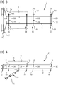
- FIG 1 shows schematically a three-dimensional view of a seat unit 2.
- FIG 2 is also a side view, in 3 a top view and in FIG 4 a front view of this seat unit 2 is shown.
- the seat unit can, for example, be a seat unit for a mobile unit, in particular for a rail vehicle.
- the seat unit 2 has a seat 4 .
- the seat 4 comprises a seat surface element 6.
- the seat 4 can also have other elements which are not shown here for the sake of clarity.
- the seat is in the Figures 1 to 4 only indicated by dashed lines, so that the other elements of the seat unit 2 are visible.
- the seat unit has a support arm 8 .
- the support arm 8 is an endless profile brought to length, in particular a lengthened, roll-formed endless profile.
- the support arm 8 is in one piece.
- the support arm 8 is designed as a cantilever support arm. This means that the support arm is designed to be attached exclusively to a side wall of the mobile unit.
- the seat unit 2 includes a means 10 for fastening the support arm 8 to the side wall of the mobile unit.
- the means 10 for fastening the Support arm 8 includes a wall bracket 12 and a bracket 14. Using the means 10 for attaching the support arm 8, the support arm 8 can be attached to a side wall of the mobile unit.
- the seat 4 is attached to the support arm 8 using support members 16 .
- the seat 4 is attached to the support arm 8 using two support members 16 .
- the seat unit 2 comprises these two support elements 16.
- Each of the support elements 16 comprises at least one seat attachment element 18, by means of which the respective support element 16 is firmly connected to the seat 4.
- the support elements 16 are arranged in such a way that the seat attachment elements 18 are arranged outside of the support arm 8 .
- each of the support elements 16 comprises two seat attachment elements 18.
- Each of the support elements 16 has two opposite ends in its longitudinal direction.
- the two seat attachment members 18 of each support member 16 are disposed at opposite ends of the respective support member 16, respectively.
- each of the support elements 16 in this exemplary embodiment has a rib 20 that can be inserted.
- Each of the insertable ribs 20 is at least partially inserted into the support arm 8 .
- the support arm 8 has several cutouts 22 .
- the recesses 22 are slot-shaped. In particular, the recesses 22 run in the transverse direction of the support arm 8.
- Each of the support elements 16 is partially inserted into at least one of the recesses 22 in each case.
- the insertable rib 20 is in each case at least partially inserted, in particular inserted, into at least one of the recesses 22 .
- the longitudinal direction of the respective support element 16 runs in each case essentially parallel to a transverse direction of the support arm 8.
- the transverse direction of the support arm 8 and the longitudinal direction of the support arm 8 are perpendicular to one another. Furthermore, the transverse direction runs essentially horizontally.
- the seat 4 is immovable relative to the support arm 8 using the support members 16. This means that the seat 4 cannot be moved relative to the support arm 8 using the support members 16.
- each of the seat fastening elements 18 comprises a threaded bore 24.
- Each of the seat fastening elements 18 is connected to the seat 4 via the respective threaded bore 24 using a screw connection.
- each of the support elements 16 is connected to the support arm 8 using a welded connection.
- the respective rib 20 is connected to the respective at least one recess 22, into which the respective rib 20 is inserted, by connecting a welded joint.
- each rib 20 is connected to each two seat attachment elements 18 using a welded connection.
- the seat 4 is spaced from the support arm 8 using the support members 16 .
- the seat attachment elements 18 are spaced from the support arm 8 in this exemplary embodiment.
- the seat fastening elements 18 are spaced apart from the support arm in the transverse direction of the support arm 8 (cf. 3 ).
- the seat unit 2 has two further support elements 16 .
- a further seat (not shown) could be connected to the support arm 8 via the two further support elements 16 .
- All support elements 16 of the seat unit 2 are preferably identical in structure to one another, as shown in this exemplary embodiment.
- the support elements 16 can be freely positioned on the support arm 8, depending on where the recesses 22 are made.
- the seat fastening elements 18 can be freely positioned relative to the support arm 8 . In this way, the seat 4 can also be freely positioned. In addition, the seat 4 can be freely selected in this way.
- FIG 5 and 6 show another seat unit 26.
- FIG 5 a three-dimensional view and 6 a front view of the seat unit 26.
- the seat 4 is connected to the support arm 8 via four support elements 16 .
- Each of the support members 16 includes a rib 20 and a single seat attachment member 18.
- the support member 16 is formed such that the seat 4 partially rests on a surface of the support arm 8. As shown in FIG.
- the seat unit 26 comprises these four support elements 16.
- the seat unit 26 comprises four further support elements 16.
- a further seat (not shown) could be connected to the support arm 8 using the four further support elements 16.
Landscapes
- Engineering & Computer Science (AREA)
- Mechanical Engineering (AREA)
- Aviation & Aerospace Engineering (AREA)
- Transportation (AREA)
- Seats For Vehicles (AREA)
- Fittings On The Vehicle Exterior For Carrying Loads, And Devices For Holding Or Mounting Articles (AREA)
- Motorcycle And Bicycle Frame (AREA)
- Automatic Cycles, And Cycles In General (AREA)
- Air Bags (AREA)
Description
- Die Erfindung bezieht sich auf eine Sitzeinheit mit zumindest einem Tragarm, wobei der Sitz unter Verwendung von Tragelementen an dem Tragarm befestigt ist, wobei jedes der Tragelemente jeweils zumindest ein Sitzbefestigungselement umfasst, mittels welchem das jeweilige Tragelement fest mit dem Sitz verbunden ist, und wobei die Tragelemente derart angeordnet sind, dass die Sitzbefestigungselemente außerhalb des Tragarms angeordnet sind. Außerdem bezieht sich die Erfindung auf eine mobile Einheit mit einer solchen Sitzeinheit.
- Eine Sitzeinheit der vorstehenden Art ist beispielsweise aus der
DE 20 2014 103167 U1 bekannt. Die dort eingesetzten Tragelemente weisen eine allgemeine Dreiecksform auf und umgreifen einen vorgesehenen Tragarm. - Üblicherweise wird für jeden Sitz-Typ ein an den Sitz-Typ angepasster Tragarm entwickelt.
- Üblicherweise umfasst der Tragarm Gewindebohrungen zur Befestigung des Sitzes. Je nach Sitztyp müssen die Gewindebohrungen an unterschiedlichen Positionen in den Tragarm eingebracht werden/sein. Derzeit ist es üblich, je nach zu verwendendem Sitztyp verschiedene Abmaße des Tragarms zu wählen. Es müssen also für verschiedene Sitztypen verschiedene Targarmtypen vorgehalten werden, was sowohl Entwicklungskosten als auch Lagerkosten erhöht.
- Um die Flexibilität zu erhöhen, ist in der
WO 2013/164151 A1 ein Tragarm vorgesehen, wobei innerhalb des Tragarms Sitzbefestigungselemente mit Gewindebohrungen positioniert werden. Dennoch können an diesem Sitzträger keine Sitze angebracht werden, deren Anbindepunkte zu weit auseinander liegen. - Eine Aufgabe der Erfindung ist es, eine Sitzeinheit bereitzustellen, die einfach aufgebaut ist, wobei der Sitz flexibel ausgewählt und flexibel angeordnet werden kann.
- Die Aufgabe wird dadurch gelöst, dass der Tragarm mehrere schlitzförmige Aussparungen aufweist und
- jedes der Tragelemente jeweils teilweise in zumindest einer der Aussparungen eingesetzt ist und
- jedes der Tragelemente jeweils eine einsteckbare Rippe aufweist, welche jeweils zumindest in eine der Aussparungen des Tragarms eingesteckt ist.
- Das heißt, dass vorzugsweise der Sitz, insbesondere über die Sitzbefestigungselemente, fest mit den Tragelementen verbunden ist. Zweckmäßigerweise sind die Tragelemente wiederum fest mit dem Tragarm verbunden. Zumindest eine der Verbindungen kann eine lösbare Verbindung sein. Weiter kann zumindest eine der Verbindungen eine nicht-lösbare Verbindung sein.
- Vorzugsweise sind die Tragelemente, insbesondere über die Sitzbefestigungselemente, an dem Sitz befestigt. Weiter sind die Tragelemente vorzugsweise an dem Tragarm befestigt.
- Auf diese Weise kann auf eine direkte, unmittelbare Befestigung des Sitzes an dem Tragarm verzichtet werden.
- Zweckmäßigerweise umfasst die Sitzeinheit die Tragelemente.
- Die Position der Tragelemente kann - insbesondere je nach gewähltem Sitz - frei gewählt werden. Das heißt, dass die Tragelemente vorzugsweise frei positionierbar sind. Insbesondere können die Sitzbefestigungselemente frei positionierbar sein. Aufgrund der Verwendung der Tragelemente kann der Sitz relativ zu dem Tragarm in allen drei Raumrichtungen frei positioniert werden. Auf diese Weise ist vorzugsweise die Position des Sitzes nicht durch ein Abmaß des Tragarms festgelegt und/oder begrenzt.
- Insbesondere kann auf diese Weise der Sitz flexibel ausgewählt werden. Weiter kann auf diese Weise der Sitz flexibel angeordnet werden.
- Unter Verwendung der Tragelemente kann ein einziger Tragarmtyp für verschiedenste Sitztypen genutzt werden. Auf diese Weise können Kosten, wie z.B. Entwicklungskosten, Lagerkosten usw., reduziert werden.
- Die erfindungsgemäße Sitzeinheit kann weitere Vorteile aufweisen: Zweckmäßigerweise ist die Sitzeinheit einfach aufgebaut. Vorzugsweise ist die Sitzeinheit außerdem einfach zu montieren. Weiter ist es vorteilhaft, wenn die Sitzeinheit wartungsarm ist. Außerdem kann die Sitzeinheit ein besonders geringes Gewicht aufweisen. Ferner kann die Sitzeinheit kostengünstig sein. Beispielsweise können Herstellungskosten, Wartungskosten und/oder Transportkosten gering sein.
- Die Sitzeinheit kann eine Sitzeinheit für eine stationäre Einheit, beispielsweise für ein Gebäude, sein.
- Es ist bevorzugt, wenn die Sitzeinheit eine Sitzeinheit für eine mobile Einheit, insbesondere für ein Fahrzeug, ist. Beispielsweise kann der Sitz ein Fahrgastsitz für ein Fahrzeug sein, beispielsweise für einen Bus, für ein Wohnmobil, für ein Schienenfahrzeug, für ein Flugzeug, für ein Schiff o. Ä..
- Weiter kann die Sitzeinheit eine Sitzeinheit für einen Teil eines Fahrzeugs sein, beispielsweise für einen Wagon eines Schienenfahrzeugs.
- Der Sitz kann beispielsweise als Einzelsitz für eine einzelne Person ausgeführt sein. Weiter kann der Sitz z. B. als Sitzbank für mehrere Personen ausgeführt sein.
- Zweckmäßigerweise umfasst der Sitz zumindest ein Sitzflächenelement. Weiter kann der Sitz eine Rückenlehne und/oder mindestens eine Armlehne aufweisen.
- Vorzugsweise ist der Tragarm langgestreckt. Zweckmäßigerweise ist der Sitz unter Verwendung von den Tragelementen auf dem Tragarm befestigt.
- Es ist vorteilhaft, wenn der Sitz unter Verwendung der Tragelemente relativ zu dem Tragarm unbeweglich ist. Das heißt, dass der Sitz unter Verwendung der Tragelemente nicht relativ zu dem Tragarm bewegt werden kann. Vorzugsweise lassen die Tragelemente eine Bewegung des Sitzes relativ zu dem Tragarm nicht zu.
- Es ist jedoch möglich, dass unabhängig von den Tragelementen, beispielsweise innerhalb des Sitzes, ein Mechanismus zum Bewegen zumindest eines Teils des Sitzes relativ zu dem Tragarm vorgesehen ist.
- Vorzugsweise ist jedes der Sitzbefestigungselemente fest mit dem Sitz verbunden. Es ist vorteilhaft, wenn jedes der Sitzbefestigungselemente lösbar mit dem Sitz verbunden ist. Beispielsweise kann jedes der Sitzbefestigungselemente jeweils unter Verwendung einer Klemmverbindung mit dem Sitz verbunden sein.
- Es ist vorteilhaft, wenn jedes der Sitzbefestigungselemente jeweils unter Verwendung einer Schraubverbindung mit dem Sitz verbunden ist. Beispielsweise kann jedes der Sitzbefestigungselemente jeweils eine Gewindebohrung umfassen.
- Vorzugsweise ist jedes der Tragelemente fest mit dem Tragarm verbunden. Jedes der Tragelemente kann lösbar mit dem Tragarm verbunden sein. Es ist vorteilhaft, wenn jedes der Tragelemente nicht-lösbar mit dem Tragarm verbunden ist.
- Vorteilhafterweise ist jedes der Tragelemente jeweils unter Verwendung einer Schweißverbindung mit dem Tragarm verbunden. Gemäß der Erfindung weist der Tragarm mehrere Aussparungen auf. Jedes der Tragelemente ist jeweils teilweise in zumindest einer der Aussparungen eingesetzt. Zweckmäßigerweise sind die Tragelemente derart eingesetzt, dass die Sitzbefestigungselemente außerhalb des Tragarms angeordnet sind. Das heißt, es ist bevorzugt, wenn die Sitzbefestigungselemente nicht in die Aussparungen eingesetzt sind.
- Die Aussparungen können beispielsweise unter Verwendung von Laserschneiden in den Tragarm eingebracht worden sein.
- Zweckmäßigerweise ist die Form der jeweiligen Aussparung an die Form des jeweiligen Tragelements angepasst. Weiter kann die Form des jeweiligen Tragelements an die Form der jeweiligen Aussparung angepasst sein.
- Die Aussparungen sind jeweils schlitzförmig ausgebildet.
- Gemäß der Erfindung weist jedes der Tragelemente jeweils eine einsteckbare Rippe auf. Zweckmäßigerweise ist die jeweilige einsteckbare Rippe jeweils zumindest teilweise in den Tragarm eingesteckt. Die jeweilige einsteckbare Rippe ist zumindest teilweise in eine jeweilige Aussparung des Tragarms eingesteckt und/oder eingesetzt.
- Vorzugsweise ist die Rippe zumindest im Wesentlichen plattenförmig.
- Zweckmäßigerweise ist jeweils eine der Rippen fest mit zumindest einem der Sitzbefestigungselemente verbunden. Insbesondere kann jeweils eine der Rippen nicht-lösbar mit zumindest einem der Sitzbefestigungselemente verbunden sein, z. B. jeweils unter Verwendung einer Schweißverbindung.
- Ferner kann das Tragelement einteilig ausgeführt sein.
- Es ist bevorzugt, wenn jedes der Tragelemente in seiner Längsrichtung zwei gegenüberliegende Enden aufweist. Weiter ist es vorteilhaft, wenn jedes der Tragelemente jeweils zwei Sitzbefestigungselemente umfasst. Zweckmäßigerweise sind die jeweiligen zwei Sitzbefestigungselemente jeweils an den gegenüberliegenden Enden des jeweiligen Tragelements angeordnet.
- Die Längsrichtung des jeweiligen Tragelements kann jeweils im Wesentlichen parallel zu einer Querrichtung des Tragarms verlaufen. Vorzugsweise verläuft die Längsrichtung des jeweiligen Tragelements zumindest im Wesentlichen horizontal. Als Querrichtung des Targarms kann diejenige Richtung des Tragarms aufgefasst werden, welche senkrecht zu einer Längsrichtung des Tragarms verläuft. Das heißt, dass die Längsrichtung des jeweiligen Tragelements jeweils im Wesentlichen senkrecht zu der Längsrichtung des Tragarms verlaufen kann.
- Als Längsrichtung eines Elements kann die Richtung der längsten Ausdehnung dieses Elements aufgefasst werden. Zweckmäßigerweise verläuft die Querrichtung eines Elements senkrecht zu der Längsrichtung dieses Elements. Weiter ist es vorteilhaft, wenn die Querrichtung zumindest im Wesentlichen horizontal verläuft.
- Falls jedes der Tragelemente die zuvor genannte Rippe umfasst, kann beispielsweise eine flächige Seite der Rippe zumindest im Wesentlichen senkrecht zur Längsrichtung des Tragarms stehen.
- Ferner kann jedes der Tragelemente jeweils eine Verbindungsfläche aufweisen. Vorzugsweise ist die jeweilige Form der jeweiligen Verbindungsfläche an die Form einer Oberfläche des Tragarms angepasst. Jede der Verbindungsflächen kann mit der Oberfläche des Tragarms fest verbunden sein.
- Der Sitz kann unter Verwendung der Tragelemente von dem Tragarm beabstandet sein.
- Weiter kann der Sitz eine Oberfläche des Tragarms teilweise berühren.
- Vorzugsweise ist der Tragarm ein auf eine vorgegebene Länge gebrachtes Endlosprofil. Beispielsweise kann der Tragarm ein auf eine vorgegebene Länge gebrachtes rollgeformtes Endlosprofil sein. Weiter kann der Tragarm ein auf eine vorgegebene Länge gebrachtes Strangpressprofil sein.
- Der Tragarm kann mehrteilig sein. Vorzugsweise ist der Tragarm maximal zweiteilig. Insbesondere kann der Tragarm einteilig sein.
- Die Sitzeinheit kann weitere Elemente aufweisen. Zum Beispiel kann die Sitzeinheit Mittel zur Befestigung des Tragarms aufweisen. Beispielsweise kann der Tragarm unter Verwendung der Mittel zur Befestigung des Tragarms an einem Fußboden und/oder an einer Seitenwand einer mobilen oder einer stationären Einheit befestigt werden. Die mobile bzw. die stationäre Einheit kann die zuvor genannte mobile bzw. stationäre Einheit sein.
- Der Tragarm kann beispielsweise als Cantilever-Tragarm zur ausschließlichen Befestigung an einer Seitenwand einer mobilen Einheit ausgebildet sein. In diesem Fall kann das Mittel zur Befestigung des Tragarms ein Mittel zur ausschließlichen Befestigung des Tragarms an der Seitenwand der mobilen Einheit sein. Die mobile Einheit kann die zuvor genannte mobile Einheit sein.
- Ferner ist die Erfindung gerichtet auf eine mobile Einheit mit der erfindungsgemäßen Sitzeinheit und/oder eine seiner Weiterbildungen.
- Die mobile Einheit kann ein Fahrzeug oder ein Teil eines Fahrzeugs sein. Beispielsweise kann die mobile Einheit ein Bus, ein Schienenfahrzeug, ein Flugzeug oder ein Schiff sein. Weiter kann die mobile Einheit beispielsweise ein Wagon eines Schienenfahrzeugs sein.
- Die bisher gegebene Beschreibung vorteilhafter Ausgestaltungen der Erfindung enthält zahlreiche Merkmale, die in den einzelnen Unteransprüchen teilweise zu mehreren zusammengefasst wiedergegeben sind. Diese Merkmale können jedoch zweckmäßigerweise auch einzeln betrachtet und zu sinnvollen weiteren Kombinationen zusammengefasst werden. Insbesondere sind diese Merkmale jeweils einzeln und in beliebiger geeigneter Kombination mit der erfindungsgemäßen Sitzeinheit und der erfindungsgemäßen mobilen Einheit kombinierbar.
- Auch wenn in der Beschreibung bzw. in den Patentansprüchen einige Begriffe jeweils im Singular oder in Verbindung mit einem Zahlwort verwendet werden, soll der Umfang der Erfindung für diese Begriffe nicht auf den Singular oder das jeweilige Zahlwort eingeschränkt sein.
- Die oben beschriebenen Eigenschaften, Merkmale und Vorteile dieser Erfindung sowie die Art und Weise, wie diese erreicht werden, werden klarer und deutlicher verständlich im Zusammenhang mit der folgenden Beschreibung der Ausführungsbeispiele, die im Zusammenhang mit den Zeichnungen näher erläutert werden. Die Ausführungsbeispiele dienen der Erläuterung der Erfindung und beschränken die Erfindung nicht auf die darin angegebene Kombination von Merkmalen, auch nicht in Bezug auf funktionale Merkmale. Außerdem können dazu geeignete Merkmale eines jeden Ausführungsbeispiels auch explizit isoliert betrachtet, aus einem Ausführungsbeispiel entfernt, in ein anderes Ausführungsbeispiel zu dessen Ergänzung eingebracht und mit einem beliebigen der Ansprüche kombiniert werden.
- Es zeigen:
- FIG 1
- eine dreidimensionale Ansicht einer Sitzeinheit,
- FIG 2
- eine Seitenansicht der Sitzeinheit aus
FIG 1 , - FIG 3
- eine Draufsicht der Sitzeinheit aus
FIG 1 und FIG 2 , - FIG 4
- eine Frontansicht der Sitzeinheit aus den
Figuren 1 bis 3 , - FIG 5
- eine dreidimensionale Ansicht einer anderen Sitzeinheit und
- FIG 6
- eine Frontansicht der Sitzeinheit aus
FIG 5 . -
FIG 1 zeigt schematisch eine dreidimensionale Ansicht einer Sitzeinheit 2. InFIG 2 ist außerdem eine Seitenansicht, inFIG 3 eine Draufsicht und inFIG 4 eine Frontansicht dieser Sitzeinheit 2 gezeigt. Die Sitzeinheit kann beispielsweise eine Sitzeinheit für eine mobile Einheit sein, insbesondere für ein Schienenfahrzeug. - Die Sitzeinheit 2 weist einen Sitz 4 auf. Der Sitz 4 umfasst ein Sitzflächenelement 6. Außerdem kann der Sitz 4 noch weitere Elemente aufweisen, welche hier der Übersichtlichkeit halber nicht gezeigt sind. Der Sitz ist in den
Figuren 1 bis 4 nur mittels gestrichelter Linien angedeutet, sodass die weiteren Elemente der Sitzeinheit 2 sichtbar sind. - Außerdem weist die Sitzeinheit einen Tragarm 8 auf. Der Tragarm 8 ist ein auf Länge gebrachtes Endlosprofil, insbesondere ein auf Länge gebrachtes rollgeformtes Endlosprofil. Ferner ist der Tragarm 8 einteilig. In diesem Ausführungsbeispiel ist der Tragarm 8 als Cantilever-Tragarm ausgebildet. Das heißt, dass der Tragarm zur ausschließlichen Befestigung an einer Seitenwand der mobilen Einheit ausgebildet ist.
- Ferner umfasst die Sitzeinheit 2 ein Mittel 10 zur Befestigung des Tragarms 8 an der Seitenwand der mobilen Einheit. In diesem Beispiel umfasst das Mittel 10 zur Befestigung des Tragarms 8 eine Wandhalterung 12 und eine Stütze 14. Unter Verwendung des Mittels 10 zur Befestigung des Tragarms 8, kann der Tragarm 8 an einer Seitenwand der mobilen Einheit befestigt werden.
- Der Sitz 4 ist unter Verwendung von Tragelementen 16 an dem Tragarm 8 befestigt. In diesem Beispiel ist der Sitz 4 unter Verwendung von zwei Tragelementen 16 an dem Tragarm 8 befestig. Die Sitzeinheit 2 umfasst diese zwei Tragelemente 16.
- Jedes der Tragelemente 16 umfasst jeweils zumindest ein Sitzbefestigungselement 18, mittels welchem das jeweilige Tragelement 16 fest mit dem Sitz 4 verbunden ist. Die Tragelemente 16 sind derart angeordnet, dass die Sitzbefestigungselemente 18 außerhalb des Tragarms 8 angeordnet sind.
- In diesem Ausführungsbeispiel umfasst jedes der Tragelemente 16 jeweils zwei Sitzbefestigungselemente 18. Jedes der Tragelemente 16 weist in seiner Längsrichtung zwei gegenüberliegende Enden auf. Die zwei Sitzbefestigungselemente 18 eines jeden Tragelements 16 sind jeweils an den gegenüberliegenden Enden des jeweiligen Tragelements 16 angeordnet.
- Außerdem weist jedes der Tragelemente 16 in diesem Ausführungsbeispiel jeweils eine einsteckbare Rippe 20 auf. Jede der einsteckbaren Rippen 20 ist jeweils zumindest teilweise in den Tragarm 8 eingesteckt.
- Der Tragarm 8 weist mehrere Aussparungen 22 auf. Die Aussparungen 22 sind schlitzförmig ausgeführt. Insbesondere verlaufen die Aussparungen 22 in Querrichtung des Tragarms 8. Jedes der Tragelemente 16 ist jeweils teilweise in jeweils zumindest einer der Aussparungen 22 eingesetzt. Insbesondere ist die einsteckbare Rippe 20 jeweils zumindest teilweise in jeweils zumindest eine der Aussparungen 22 eingesetzt, insbesondere eingesteckt.
- Die Längsrichtung des jeweiligen Tragelements 16 verläuft jeweils im Wesentlichen parallel zu einer Querrichtung des Tragarms 8. Dabei stehen die Querrichtung des Tragarms 8 und die Längsrichtung des Tragarms 8 senkrecht zueinander. Weiter verläuft die Querrichtung im Wesentlichen horizontal.
- Der Sitz 4 ist unter Verwendung der Tragelemente 16 unbeweglich relativ zu dem Tragarm 8. Das heißt, dass der Sitz 4 unter der Verwendung der Tragelemente 16 nicht relativ zu dem Tragarm 8 bewegt werden kann.
- In diesem Ausführungsbeispiel umfasst jedes der Sitzbefestigungselemente 18 eine Gewindebohrung 24. Jedes der Sitzbefestigungselemente 18 ist jeweils über die jeweilige Gewindebohrung 24 jeweils unter Verwendung einer Schraubverbindung mit dem Sitz 4 verbunden. Außerdem ist jedes der Tragelemente 16 jeweils unter Verwendung einer Schweißverbindung mit dem Tragarm 8 verbunden. Insbesondere ist die jeweilige Rippe 20 jeweils unter Verbindung einer Schweißverbindung mit der jeweils zumindest einen Aussparung 22, in welche die jeweilige Rippe 20 eingesetzt ist, verbunden. Ferner ist jeweils eine Rippe 20 mit jeweils zwei Sitzbefestigungselementen 18 unter Verwendung einer Schweißverbindung verbunden.
- In diesem Ausführungsbeispiel ist der Sitz 4 unter der Verwendung der Tragelemente 16 von dem Tragarm 8 beabstandet. Außerdem sind die Sitzbefestigungselemente 18 in diesem Ausführungsbeispiel von dem Tragarm 8 beabstandet. Insbesondere sind die Sitzbefestigungselemente 18 in Querrichtung des Tragarms 8 von dem Tragarm beabstandet (vgl.
FIG 3 ). - In diesem Beispiel weist die Sitzeinheit 2 zwei weitere Tragelemente 16 auf. Ein weiterer Sitz (nicht gezeigt) könnte über die zwei weiteren Tragelemente 16 mit dem Tragarm 8 verbunden sein/werden.
- Vorzugweise sind alle Tragelemente 16 der Sitzeinheit 2 vom Aufbau identisch zueinander, wie in diesem Ausführungsbeispiel gezeigt.
- Die Tragelemente 16 können frei an dem Tragarm 8 positioniert werden, je nachdem wo die Aussparungen 22 eingebracht werden. Außerdem sind die Sitzbefestigungselemente 18 relativ zu dem Tragarm 8 frei positionierbar. Auf diese Weise kann der Sitz 4 ebenfalls frei positioniert werden. Außerdem kann auf diese Weise der Sitz 4 frei ausgewählt werden.
-
FIG 5 und FIG 6 zeigen eine andere Sitzeinheit 26. Insbesondere zeigtFIG 5 eine dreidimensionale Ansicht undFIG 6 eine Frontansicht der Sitzeinheit 26. - Die nachfolgende Beschreibung beschränkt sich im Wesentlichen auf die Unterschiede zum Ausführungsbeispiel aus den
Figuren 1 bis 4 , auf die bezüglich gleichbleibender Merkmale und Funktionen verwiesen wird. Im Wesentlichen gleichbleibende Elemente werden grundsätzlich mit dem gleichen Bezugszeichen bezeichnet und nicht erwähnte Merkmale sind in das folgende Ausführungsbeispiel übernommen, ohne dass sie erneut beschrieben sind. - Der Sitz 4 ist über vier Tragelemente 16 mit dem Tragarm 8 verbunden. Jedes der Tragelemente 16 umfasst eine Rippe 20 und ein einziges Sitzbefestigungselement 18. Außerdem ist das Tragelement 16 derart ausgebildet, dass der Sitz 4 teilweise auf einer Oberfläche des Tragarms 8 aufliegt.
- Die Sitzeinheit 26 umfasst diese vier Tragelemente 16.
- Außerdem umfasst die Sitzeinheit 26 weitere vier Tragelemente 16. Ein weiterer Sitz (nicht gezeigt) könnte unter Verwendung der vier weiteren Tragelemente 16 mit dem Tragarm 8 verbunden werden/sein.
- Obwohl die Erfindung im Detail durch die bevorzugten Ausführungsbeispiele näher illustriert und beschrieben wurde, so ist die Erfindung nicht durch die offenbarten Beispiele eingeschränkt und andere Variationen können vom Fachmann hieraus abgeleitet werden, ohne den durch die Ansprüche definierten Schutzumfang der Erfindung zu verlassen.
Claims (12)
- Sitzeinheit (2, 26) mit zumindest einem Sitz (4) und einem Tragarm (8),wobei der Sitz (4) unter Verwendung von Tragelementen (16) an dem Tragarm (8) befestigt ist,wobei jedes der Tragelemente (16) jeweils zumindest ein Sitzbefestigungselement (18) umfasst, mittels welchem das jeweilige Tragelement (16) fest mit dem Sitz (4) verbunden ist, undwobei die Tragelemente (16) derart angeordnet sind, dass die Sitzbefestigungselemente (18) außerhalb des Tragarms (8) angeordnet sind,dadurch gekennzeichnet, dassder Tragarm (8) mehrere schlitzförmige Aussparungen (22) aufweist undjedes der Tragelemente (16) jeweils teilweise in zumindest einer der Aussparungen (22) eingesetzt ist undjedes der Tragelemente (16) jeweils eine einsteckbare Rippe (20) aufweist, welche jeweils zumindest in eine der Aussparungen (22) des Tragarms (8) eingesteckt ist.
- Sitzeinheit (2, 26) nach Anspruch 1,
dadurch gekennzeichnet, dass
der Sitz (4) unter Verwendung der Tragelemente (16) relativ zu dem Tragarm (8) unbeweglich ist. - Sitzeinheit (2, 26) nach Anspruch 1 oder 2,
dadurch gekennzeichnet, dass
jedes der Sitzbefestigungselemente (18) jeweils unter Verwendung einer Schraubverbindung mit dem Sitz (4) verbunden ist. - Sitzeinheit (2, 26) nach einem der vorhergehenden Ansprüche,
dadurch gekennzeichnet, dass
jedes der Tragelemente (16) jeweils unter Verwendung einer Schweißverbindung mit dem Tragarm (8) verbunden ist. - Sitzeinheit (2) nach einem der vorhergehenden Ansprüche, dadurch gekennzeichnet, dassjedes der Tragelemente (16) in seiner Längsrichtung zwei gegenüberliegende Enden aufweist undjedes der Tragelemente (16) jeweils zwei Sitzbefestigungselemente (18) umfasst, welche jeweils an den gegenüberliegenden Enden des jeweiligen Tragelements (16) angeordnet sind.
- Sitzeinheit (2) nach Anspruch 5,
dadurch gekennzeichnet, dass
die Längsrichtung des jeweiligen Tragelements (16) jeweils im Wesentlichen parallel zu einer Querrichtung des Tragarms (8) verläuft. - Sitzeinheit (2, 26) nach einem der vorhergehenden Ansprüche,dadurch gekennzeichnet, dassjedes der Tragelemente (16) jeweils eine Verbindungsfläche aufweist, deren jeweilige Form an die Form einer Oberfläche des Tragarms (8) angepasst ist, undjede der Verbindungsflächen mit der Oberfläche des Tragarms (8) fest verbunden ist.
- Sitzeinheit (2) nach einem der vorhergehenden Ansprüche, dadurch gekennzeichnet, dass
der Sitz (4) unter Verwendung der Tragelemente (16) von dem Tragarm (8) beabstandet ist. - Sitzeinheit (2, 26) nach einem der vorhergehenden Ansprüche,
dadurch gekennzeichnet, dass
der Tragarm (8) ein auf eine vorgegebene Länge gebrachtes Endlosprofil ist, insbesondere ein auf eine vorgegebene Länge gebrachtes rollgeformtes Endlosprofil oder ein auf eine vorgegebene Länge gebrachtes Strangpressprofil. - Sitzeinheit (2, 26) nach einem der vorhergehenden Ansprüche,dadurch gekennzeichnet, dassder Tragarm (8) maximal zweiteilig ist,insbesondere dass der Tragarm (8) einteilig ist.
- Sitzeinheit (2, 26) nach einem der vorhergehenden Ansprüche,
dadurch gekennzeichnet, dass
der Tragarm (8) als Cantilever-Tragarm zur ausschließlichen Befestigung an einer Seitenwand einer mobilen Einheit ausgebildet ist. - Mobile Einheit mit der Sitzeinheit (2, 26) nach einem der vorhergehenden Ansprüche.
Priority Applications (2)
| Application Number | Priority Date | Filing Date | Title |
|---|---|---|---|
| RS20220756A RS63494B1 (sr) | 2017-11-02 | 2018-10-10 | Jedinica za sedište i mobilna jedinica |
| HRP20220959TT HRP20220959T1 (hr) | 2017-11-02 | 2018-10-10 | Jedinstveni sklop za sjedenje i mobilni sklop |
Applications Claiming Priority (2)
| Application Number | Priority Date | Filing Date | Title |
|---|---|---|---|
| DE102017219485.5A DE102017219485A1 (de) | 2017-11-02 | 2017-11-02 | Sitzeinheit und mobile Einheit |
| PCT/EP2018/077544 WO2019086217A1 (de) | 2017-11-02 | 2018-10-10 | Sitzeinheit und mobile einheit |
Publications (2)
| Publication Number | Publication Date |
|---|---|
| EP3676150A1 EP3676150A1 (de) | 2020-07-08 |
| EP3676150B1 true EP3676150B1 (de) | 2022-06-01 |
Family
ID=64023980
Family Applications (1)
| Application Number | Title | Priority Date | Filing Date |
|---|---|---|---|
| EP18793573.9A Active EP3676150B1 (de) | 2017-11-02 | 2018-10-10 | Sitzeinheit und mobile einheit |
Country Status (10)
| Country | Link |
|---|---|
| EP (1) | EP3676150B1 (de) |
| CN (1) | CN213705436U (de) |
| DE (1) | DE102017219485A1 (de) |
| ES (1) | ES2924884T3 (de) |
| HR (1) | HRP20220959T1 (de) |
| PL (1) | PL3676150T3 (de) |
| PT (1) | PT3676150T (de) |
| RS (1) | RS63494B1 (de) |
| RU (1) | RU201516U1 (de) |
| WO (1) | WO2019086217A1 (de) |
Cited By (4)
| Publication number | Priority date | Publication date | Assignee | Title |
|---|---|---|---|---|
| DE102023211302A1 (de) * | 2023-11-14 | 2025-05-15 | Siemens Mobility GmbH | Sitzanordnung |
| EP4667281A1 (de) * | 2024-06-19 | 2025-12-24 | F.I.S.A. - Fabbrica Italiana Sedili Autoferroviari - S.r.l. | Stützvorrichtung für mindestens einen sitz von strassen-schienenfahrzeugen für den öffentlichen transport und verfahren zu ihrer herstellung und installation |
| EP4674681A1 (de) | 2024-07-02 | 2026-01-07 | Siemens Mobility GmbH | Sitzanordnung |
| DE102024207662A1 (de) | 2024-08-12 | 2026-02-12 | Siemens Mobility GmbH | Sitzanordnung |
Family Cites Families (8)
| Publication number | Priority date | Publication date | Assignee | Title |
|---|---|---|---|---|
| CA1020854A (en) * | 1975-04-10 | 1977-11-15 | Otaco Limited | Transportation seating construction and system |
| DE19526840A1 (de) * | 1995-07-22 | 1997-01-23 | Gunnar Kolb | Untergestell für einen Fahrgastsitz |
| DE10126404C2 (de) * | 2001-05-22 | 2003-08-21 | Daimlerchrysler Rail Systems | Sitzbefestigung |
| US7434877B2 (en) * | 2005-09-23 | 2008-10-14 | American Seating Company | Transportation seating system |
| EP1864855A1 (de) * | 2006-06-09 | 2007-12-12 | Schlegel Ag | Sitzträger |
| RU110693U1 (ru) * | 2011-02-16 | 2011-11-27 | Сименс Акциенгезелльшафт | Сиденье транспортного средства, в частности пассажирское сиденье в транспортном средстве для перевозки пассажиров |
| DE102012207446A1 (de) * | 2012-05-04 | 2013-11-07 | Siemens Aktiengesellschaft | Cantilever-Sitzträger |
| DE202014103167U1 (de) * | 2014-07-10 | 2014-07-25 | Borcad Cz S.R.O. | Befestigungssystem von Sitzen eines Verkehrsmittels |
-
2017
- 2017-11-02 DE DE102017219485.5A patent/DE102017219485A1/de not_active Ceased
-
2018
- 2018-10-10 CN CN201890001328.7U patent/CN213705436U/zh active Active
- 2018-10-10 ES ES18793573T patent/ES2924884T3/es active Active
- 2018-10-10 RS RS20220756A patent/RS63494B1/sr unknown
- 2018-10-10 EP EP18793573.9A patent/EP3676150B1/de active Active
- 2018-10-10 HR HRP20220959TT patent/HRP20220959T1/hr unknown
- 2018-10-10 PT PT187935739T patent/PT3676150T/pt unknown
- 2018-10-10 PL PL18793573.9T patent/PL3676150T3/pl unknown
- 2018-10-10 RU RU2020114499U patent/RU201516U1/ru active
- 2018-10-10 WO PCT/EP2018/077544 patent/WO2019086217A1/de not_active Ceased
Cited By (7)
| Publication number | Priority date | Publication date | Assignee | Title |
|---|---|---|---|---|
| DE102023211302A1 (de) * | 2023-11-14 | 2025-05-15 | Siemens Mobility GmbH | Sitzanordnung |
| WO2025103653A1 (de) | 2023-11-14 | 2025-05-22 | Siemens Mobility GmbH | Sitzanordnung |
| EP4667281A1 (de) * | 2024-06-19 | 2025-12-24 | F.I.S.A. - Fabbrica Italiana Sedili Autoferroviari - S.r.l. | Stützvorrichtung für mindestens einen sitz von strassen-schienenfahrzeugen für den öffentlichen transport und verfahren zu ihrer herstellung und installation |
| EP4674681A1 (de) | 2024-07-02 | 2026-01-07 | Siemens Mobility GmbH | Sitzanordnung |
| DE102024206178A1 (de) | 2024-07-02 | 2026-01-08 | Siemens Mobility GmbH | Sitzanordnung |
| DE102024207662A1 (de) | 2024-08-12 | 2026-02-12 | Siemens Mobility GmbH | Sitzanordnung |
| EP4696551A1 (de) | 2024-08-12 | 2026-02-18 | Siemens Mobility GmbH | Sitzanordnung |
Also Published As
| Publication number | Publication date |
|---|---|
| CN213705436U (zh) | 2021-07-16 |
| HRP20220959T1 (hr) | 2022-10-28 |
| RU201516U1 (ru) | 2020-12-18 |
| PL3676150T3 (pl) | 2022-09-26 |
| WO2019086217A1 (de) | 2019-05-09 |
| EP3676150A1 (de) | 2020-07-08 |
| PT3676150T (pt) | 2022-07-25 |
| RS63494B1 (sr) | 2022-09-30 |
| ES2924884T3 (es) | 2022-10-11 |
| DE102017219485A1 (de) | 2019-05-02 |
Similar Documents
| Publication | Publication Date | Title |
|---|---|---|
| DE102005042403B3 (de) | Modulares Sitzsystem für ein Fahrzeug | |
| DE102009020199B4 (de) | Bausatz füt Sitzreihen in Flugzeugen | |
| DE102014202697B4 (de) | Sitzwinkel-Einstellmechanismus und damit ausgestatteter Kindersitz | |
| EP2252508B1 (de) | Vorrichtung zur lösbaren bodenbefestigung von schränken oder dergleichen in bordküchen von flugzeugen | |
| DE102009048894B4 (de) | System zur Befestigung eines Sitzes, insbesondere eines Luftfahrzeugs, und ein solches System aufweisender Sitz | |
| DE102015117709A1 (de) | Adapterschienensystem und Verfahren zum Befestigen eines Objekts an einer Fußbodenschiene in einem Transportmittel | |
| DE102009028533B4 (de) | Befestigungssystem in einem Luft- und Raumfahrzeug | |
| EP3676150A1 (de) | Sitzeinheit und mobile einheit | |
| DE102016111999A1 (de) | Modulares Schienensystem mit Klemmbefestigung | |
| EP2569838A2 (de) | Kabelbefestigungsvorrichtung | |
| WO2016086934A1 (de) | Befestigungssystem zum befestigen eines gegenstandes in einem fahrzeug | |
| DE2828477A1 (de) | Konsole fuer einen fahrzeugsitz | |
| DE4304456C2 (de) | Anordnung mit einer längsverschiebbaren Schiene und einem daran befestigten Anschlag | |
| DE102016111983B4 (de) | Modulares Schienensystem | |
| WO2014161728A1 (de) | Befestigungsanordnung für ein innenausstattungselement am wagenkasten eines fahrzeugs | |
| DE102016111994A1 (de) | Modulares Schienensystem | |
| EP1845219B1 (de) | Tragvorrichtung für Wandverkleidungen | |
| DE102012106865B4 (de) | Fixiervorrichtung für einen Ausstattungsgegenstand an einer Fixierschiene | |
| DE102016114479A1 (de) | Frachtrückhaltesystem für Flugzeuge | |
| EP3461963B1 (de) | Trägersystem und system von verbindungselementen zur verbindung von trägern | |
| DE2426900A1 (de) | Feststellvorrichtung fuer eine fuehrungsanordnung eines gleitend einstellbaren sitzes in einem motorfahrzeug | |
| EP2508106B1 (de) | Trag- und Montageprofilen zur Fixierung von Paneelen in einem Ladenbausystem | |
| EP2283748A1 (de) | Trägersystem | |
| DE10337930A1 (de) | Fußboden eines großräumigen Fahrzeuges zur Personenbeförderung, insbesondere eines Schienenfahrzeuges | |
| EP1820729B1 (de) | Flugzeugsitzbefestigungsvorrichtung |
Legal Events
| Date | Code | Title | Description |
|---|---|---|---|
| REG | Reference to a national code |
Ref country code: HR Ref legal event code: TUEP Ref document number: P20220959 Country of ref document: HR |
|
| STAA | Information on the status of an ep patent application or granted ep patent |
Free format text: STATUS: UNKNOWN |
|
| STAA | Information on the status of an ep patent application or granted ep patent |
Free format text: STATUS: THE INTERNATIONAL PUBLICATION HAS BEEN MADE |
|
| PUAI | Public reference made under article 153(3) epc to a published international application that has entered the european phase |
Free format text: ORIGINAL CODE: 0009012 |
|
| STAA | Information on the status of an ep patent application or granted ep patent |
Free format text: STATUS: REQUEST FOR EXAMINATION WAS MADE |
|
| 17P | Request for examination filed |
Effective date: 20200403 |
|
| AK | Designated contracting states |
Kind code of ref document: A1 Designated state(s): AL AT BE BG CH CY CZ DE DK EE ES FI FR GB GR HR HU IE IS IT LI LT LU LV MC MK MT NL NO PL PT RO RS SE SI SK SM TR |
|
| AX | Request for extension of the european patent |
Extension state: BA ME |
|
| DAV | Request for validation of the european patent (deleted) | ||
| DAX | Request for extension of the european patent (deleted) | ||
| GRAP | Despatch of communication of intention to grant a patent |
Free format text: ORIGINAL CODE: EPIDOSNIGR1 |
|
| STAA | Information on the status of an ep patent application or granted ep patent |
Free format text: STATUS: GRANT OF PATENT IS INTENDED |
|
| INTG | Intention to grant announced |
Effective date: 20220215 |
|
| GRAS | Grant fee paid |
Free format text: ORIGINAL CODE: EPIDOSNIGR3 |
|
| GRAA | (expected) grant |
Free format text: ORIGINAL CODE: 0009210 |
|
| STAA | Information on the status of an ep patent application or granted ep patent |
Free format text: STATUS: THE PATENT HAS BEEN GRANTED |
|
| AK | Designated contracting states |
Kind code of ref document: B1 Designated state(s): AL AT BE BG CH CY CZ DE DK EE ES FI FR GB GR HR HU IE IS IT LI LT LU LV MC MK MT NL NO PL PT RO RS SE SI SK SM TR |
|
| REG | Reference to a national code |
Ref country code: GB Ref legal event code: FG4D Free format text: NOT ENGLISH |
|
| REG | Reference to a national code |
Ref country code: AT Ref legal event code: REF Ref document number: 1495203 Country of ref document: AT Kind code of ref document: T Effective date: 20220615 Ref country code: CH Ref legal event code: EP |
|
| REG | Reference to a national code |
Ref country code: IE Ref legal event code: FG4D Free format text: LANGUAGE OF EP DOCUMENT: GERMAN |
|
| REG | Reference to a national code |
Ref country code: DE Ref legal event code: R096 Ref document number: 502018009830 Country of ref document: DE |
|
| REG | Reference to a national code |
Ref country code: PT Ref legal event code: SC4A Ref document number: 3676150 Country of ref document: PT Date of ref document: 20220725 Kind code of ref document: T Free format text: AVAILABILITY OF NATIONAL TRANSLATION Effective date: 20220719 |
|
| REG | Reference to a national code |
Ref country code: LT Ref legal event code: MG9D |
|
| REG | Reference to a national code |
Ref country code: NL Ref legal event code: MP Effective date: 20220601 |
|
| REG | Reference to a national code |
Ref country code: ES Ref legal event code: FG2A Ref document number: 2924884 Country of ref document: ES Kind code of ref document: T3 Effective date: 20221011 |
|
| REG | Reference to a national code |
Ref country code: HR Ref legal event code: T1PR Ref document number: P20220959 Country of ref document: HR Ref country code: HR Ref legal event code: ODRP Ref document number: P20220959 Country of ref document: HR Payment date: 20221005 Year of fee payment: 5 |
|
| PG25 | Lapsed in a contracting state [announced via postgrant information from national office to epo] |
Ref country code: SE Free format text: LAPSE BECAUSE OF FAILURE TO SUBMIT A TRANSLATION OF THE DESCRIPTION OR TO PAY THE FEE WITHIN THE PRESCRIBED TIME-LIMIT Effective date: 20220601 Ref country code: NO Free format text: LAPSE BECAUSE OF FAILURE TO SUBMIT A TRANSLATION OF THE DESCRIPTION OR TO PAY THE FEE WITHIN THE PRESCRIBED TIME-LIMIT Effective date: 20220901 Ref country code: LT Free format text: LAPSE BECAUSE OF FAILURE TO SUBMIT A TRANSLATION OF THE DESCRIPTION OR TO PAY THE FEE WITHIN THE PRESCRIBED TIME-LIMIT Effective date: 20220601 Ref country code: GR Free format text: LAPSE BECAUSE OF FAILURE TO SUBMIT A TRANSLATION OF THE DESCRIPTION OR TO PAY THE FEE WITHIN THE PRESCRIBED TIME-LIMIT Effective date: 20220902 Ref country code: FI Free format text: LAPSE BECAUSE OF FAILURE TO SUBMIT A TRANSLATION OF THE DESCRIPTION OR TO PAY THE FEE WITHIN THE PRESCRIBED TIME-LIMIT Effective date: 20220601 |
|
| PG25 | Lapsed in a contracting state [announced via postgrant information from national office to epo] |
Ref country code: LV Free format text: LAPSE BECAUSE OF FAILURE TO SUBMIT A TRANSLATION OF THE DESCRIPTION OR TO PAY THE FEE WITHIN THE PRESCRIBED TIME-LIMIT Effective date: 20220601 |
|
| PG25 | Lapsed in a contracting state [announced via postgrant information from national office to epo] |
Ref country code: NL Free format text: LAPSE BECAUSE OF FAILURE TO SUBMIT A TRANSLATION OF THE DESCRIPTION OR TO PAY THE FEE WITHIN THE PRESCRIBED TIME-LIMIT Effective date: 20220601 |
|
| PG25 | Lapsed in a contracting state [announced via postgrant information from national office to epo] |
Ref country code: SM Free format text: LAPSE BECAUSE OF FAILURE TO SUBMIT A TRANSLATION OF THE DESCRIPTION OR TO PAY THE FEE WITHIN THE PRESCRIBED TIME-LIMIT Effective date: 20220601 Ref country code: SK Free format text: LAPSE BECAUSE OF FAILURE TO SUBMIT A TRANSLATION OF THE DESCRIPTION OR TO PAY THE FEE WITHIN THE PRESCRIBED TIME-LIMIT Effective date: 20220601 Ref country code: RO Free format text: LAPSE BECAUSE OF FAILURE TO SUBMIT A TRANSLATION OF THE DESCRIPTION OR TO PAY THE FEE WITHIN THE PRESCRIBED TIME-LIMIT Effective date: 20220601 Ref country code: EE Free format text: LAPSE BECAUSE OF FAILURE TO SUBMIT A TRANSLATION OF THE DESCRIPTION OR TO PAY THE FEE WITHIN THE PRESCRIBED TIME-LIMIT Effective date: 20220601 |
|
| PG25 | Lapsed in a contracting state [announced via postgrant information from national office to epo] |
Ref country code: IS Free format text: LAPSE BECAUSE OF FAILURE TO SUBMIT A TRANSLATION OF THE DESCRIPTION OR TO PAY THE FEE WITHIN THE PRESCRIBED TIME-LIMIT Effective date: 20221001 |
|
| REG | Reference to a national code |
Ref country code: DE Ref legal event code: R097 Ref document number: 502018009830 Country of ref document: DE |
|
| PG25 | Lapsed in a contracting state [announced via postgrant information from national office to epo] |
Ref country code: AL Free format text: LAPSE BECAUSE OF FAILURE TO SUBMIT A TRANSLATION OF THE DESCRIPTION OR TO PAY THE FEE WITHIN THE PRESCRIBED TIME-LIMIT Effective date: 20220601 |
|
| PLBE | No opposition filed within time limit |
Free format text: ORIGINAL CODE: 0009261 |
|
| STAA | Information on the status of an ep patent application or granted ep patent |
Free format text: STATUS: NO OPPOSITION FILED WITHIN TIME LIMIT |
|
| PG25 | Lapsed in a contracting state [announced via postgrant information from national office to epo] |
Ref country code: DK Free format text: LAPSE BECAUSE OF FAILURE TO SUBMIT A TRANSLATION OF THE DESCRIPTION OR TO PAY THE FEE WITHIN THE PRESCRIBED TIME-LIMIT Effective date: 20220601 |
|
| 26N | No opposition filed |
Effective date: 20230302 |
|
| PG25 | Lapsed in a contracting state [announced via postgrant information from national office to epo] |
Ref country code: SI Free format text: LAPSE BECAUSE OF FAILURE TO SUBMIT A TRANSLATION OF THE DESCRIPTION OR TO PAY THE FEE WITHIN THE PRESCRIBED TIME-LIMIT Effective date: 20220601 Ref country code: MC Free format text: LAPSE BECAUSE OF FAILURE TO SUBMIT A TRANSLATION OF THE DESCRIPTION OR TO PAY THE FEE WITHIN THE PRESCRIBED TIME-LIMIT Effective date: 20220601 |
|
| REG | Reference to a national code |
Ref country code: BE Ref legal event code: MM Effective date: 20221031 |
|
| PG25 | Lapsed in a contracting state [announced via postgrant information from national office to epo] |
Ref country code: LU Free format text: LAPSE BECAUSE OF NON-PAYMENT OF DUE FEES Effective date: 20221010 |
|
| PG25 | Lapsed in a contracting state [announced via postgrant information from national office to epo] |
Ref country code: BE Free format text: LAPSE BECAUSE OF NON-PAYMENT OF DUE FEES Effective date: 20221031 |
|
| REG | Reference to a national code |
Ref country code: HR Ref legal event code: ODRP Ref document number: P20220959 Country of ref document: HR Payment date: 20230928 Year of fee payment: 6 |
|
| PG25 | Lapsed in a contracting state [announced via postgrant information from national office to epo] |
Ref country code: IE Free format text: LAPSE BECAUSE OF NON-PAYMENT OF DUE FEES Effective date: 20221010 |
|
| PGFP | Annual fee paid to national office [announced via postgrant information from national office to epo] |
Ref country code: RS Payment date: 20230928 Year of fee payment: 6 Ref country code: PT Payment date: 20230925 Year of fee payment: 6 Ref country code: HR Payment date: 20230928 Year of fee payment: 6 |
|
| PGFP | Annual fee paid to national office [announced via postgrant information from national office to epo] |
Ref country code: BG Payment date: 20231020 Year of fee payment: 6 |
|
| PG25 | Lapsed in a contracting state [announced via postgrant information from national office to epo] |
Ref country code: HU Free format text: LAPSE BECAUSE OF FAILURE TO SUBMIT A TRANSLATION OF THE DESCRIPTION OR TO PAY THE FEE WITHIN THE PRESCRIBED TIME-LIMIT; INVALID AB INITIO Effective date: 20181010 |
|
| PG25 | Lapsed in a contracting state [announced via postgrant information from national office to epo] |
Ref country code: CY Free format text: LAPSE BECAUSE OF FAILURE TO SUBMIT A TRANSLATION OF THE DESCRIPTION OR TO PAY THE FEE WITHIN THE PRESCRIBED TIME-LIMIT Effective date: 20220601 |
|
| PG25 | Lapsed in a contracting state [announced via postgrant information from national office to epo] |
Ref country code: MK Free format text: LAPSE BECAUSE OF FAILURE TO SUBMIT A TRANSLATION OF THE DESCRIPTION OR TO PAY THE FEE WITHIN THE PRESCRIBED TIME-LIMIT Effective date: 20220601 |
|
| PG25 | Lapsed in a contracting state [announced via postgrant information from national office to epo] |
Ref country code: MT Free format text: LAPSE BECAUSE OF FAILURE TO SUBMIT A TRANSLATION OF THE DESCRIPTION OR TO PAY THE FEE WITHIN THE PRESCRIBED TIME-LIMIT Effective date: 20220601 |
|
| REG | Reference to a national code |
Ref country code: HR Ref legal event code: PBON Ref document number: P20220959 Country of ref document: HR Effective date: 20241010 |
|
| PG25 | Lapsed in a contracting state [announced via postgrant information from national office to epo] |
Ref country code: RS Free format text: LAPSE BECAUSE OF NON-PAYMENT OF DUE FEES Effective date: 20241010 |
|
| PG25 | Lapsed in a contracting state [announced via postgrant information from national office to epo] |
Ref country code: HR Free format text: LAPSE BECAUSE OF NON-PAYMENT OF DUE FEES Effective date: 20241010 |
|
| PG25 | Lapsed in a contracting state [announced via postgrant information from national office to epo] |
Ref country code: PT Free format text: LAPSE BECAUSE OF NON-PAYMENT OF DUE FEES Effective date: 20250410 |
|
| PG25 | Lapsed in a contracting state [announced via postgrant information from national office to epo] |
Ref country code: BG Free format text: LAPSE BECAUSE OF NON-PAYMENT OF DUE FEES Effective date: 20241010 |
|
| REG | Reference to a national code |
Ref country code: DE Ref legal event code: R081 Ref document number: 502018009830 Country of ref document: DE Owner name: SIEMENS MOBILITY GMBH, DE Free format text: FORMER OWNER: SIEMENS MOBILITY GMBH, 81739 MUENCHEN, DE |
|
| PG25 | Lapsed in a contracting state [announced via postgrant information from national office to epo] |
Ref country code: TR Free format text: LAPSE BECAUSE OF FAILURE TO SUBMIT A TRANSLATION OF THE DESCRIPTION OR TO PAY THE FEE WITHIN THE PRESCRIBED TIME-LIMIT Effective date: 20220601 |
|
| PGFP | Annual fee paid to national office [announced via postgrant information from national office to epo] |
Ref country code: GB Payment date: 20251111 Year of fee payment: 8 |
|
| PGFP | Annual fee paid to national office [announced via postgrant information from national office to epo] |
Ref country code: AT Payment date: 20250905 Year of fee payment: 8 |
|
| PGFP | Annual fee paid to national office [announced via postgrant information from national office to epo] |
Ref country code: IT Payment date: 20251027 Year of fee payment: 8 |
|
| REG | Reference to a national code |
Ref country code: CH Ref legal event code: U11 Free format text: ST27 STATUS EVENT CODE: U-0-0-U10-U11 (AS PROVIDED BY THE NATIONAL OFFICE) Effective date: 20260114 |
|
| PGFP | Annual fee paid to national office [announced via postgrant information from national office to epo] |
Ref country code: FR Payment date: 20251020 Year of fee payment: 8 |
|
| PGFP | Annual fee paid to national office [announced via postgrant information from national office to epo] |
Ref country code: CZ Payment date: 20251002 Year of fee payment: 8 |
|
| PGFP | Annual fee paid to national office [announced via postgrant information from national office to epo] |
Ref country code: PL Payment date: 20251002 Year of fee payment: 8 |
|
| PGFP | Annual fee paid to national office [announced via postgrant information from national office to epo] |
Ref country code: ES Payment date: 20260119 Year of fee payment: 8 |
|
| PGFP | Annual fee paid to national office [announced via postgrant information from national office to epo] |
Ref country code: DE Payment date: 20251219 Year of fee payment: 8 |
|
| PGFP | Annual fee paid to national office [announced via postgrant information from national office to epo] |
Ref country code: CH Payment date: 20260114 Year of fee payment: 8 |