EP3676037B1 - Cutter clamps, cutter clamp kit, and cutter clamp and holding frame systems - Google Patents
Cutter clamps, cutter clamp kit, and cutter clamp and holding frame systems Download PDFInfo
- Publication number
- EP3676037B1 EP3676037B1 EP18851371.7A EP18851371A EP3676037B1 EP 3676037 B1 EP3676037 B1 EP 3676037B1 EP 18851371 A EP18851371 A EP 18851371A EP 3676037 B1 EP3676037 B1 EP 3676037B1
- Authority
- EP
- European Patent Office
- Prior art keywords
- arm
- cutter clamp
- cutter
- parts
- rod
- Prior art date
- Legal status (The legal status is an assumption and is not a legal conclusion. Google has not performed a legal analysis and makes no representation as to the accuracy of the status listed.)
- Active
Links
Images




Classifications
-
- B—PERFORMING OPERATIONS; TRANSPORTING
- B23—MACHINE TOOLS; METAL-WORKING NOT OTHERWISE PROVIDED FOR
- B23D—PLANING; SLOTTING; SHEARING; BROACHING; SAWING; FILING; SCRAPING; LIKE OPERATIONS FOR WORKING METAL BY REMOVING MATERIAL, NOT OTHERWISE PROVIDED FOR
- B23D21/00—Machines or devices for shearing or cutting tubes
- B23D21/06—Hand-operated tube-cutters
- B23D21/10—Hand-operated tube-cutters with other cutting blades or tools
-
- B—PERFORMING OPERATIONS; TRANSPORTING
- B23—MACHINE TOOLS; METAL-WORKING NOT OTHERWISE PROVIDED FOR
- B23D—PLANING; SLOTTING; SHEARING; BROACHING; SAWING; FILING; SCRAPING; LIKE OPERATIONS FOR WORKING METAL BY REMOVING MATERIAL, NOT OTHERWISE PROVIDED FOR
- B23D45/00—Sawing machines or sawing devices with circular saw blades or with friction saw discs
- B23D45/006—Sawing machines or sawing devices with circular saw blades or with friction saw discs with means to attach the sawing device to the workpiece
-
- B—PERFORMING OPERATIONS; TRANSPORTING
- B23—MACHINE TOOLS; METAL-WORKING NOT OTHERWISE PROVIDED FOR
- B23D—PLANING; SLOTTING; SHEARING; BROACHING; SAWING; FILING; SCRAPING; LIKE OPERATIONS FOR WORKING METAL BY REMOVING MATERIAL, NOT OTHERWISE PROVIDED FOR
- B23D45/00—Sawing machines or sawing devices with circular saw blades or with friction saw discs
- B23D45/12—Sawing machines or sawing devices with circular saw blades or with friction saw discs with a circular saw blade for cutting tubes
-
- B—PERFORMING OPERATIONS; TRANSPORTING
- B23—MACHINE TOOLS; METAL-WORKING NOT OTHERWISE PROVIDED FOR
- B23D—PLANING; SLOTTING; SHEARING; BROACHING; SAWING; FILING; SCRAPING; LIKE OPERATIONS FOR WORKING METAL BY REMOVING MATERIAL, NOT OTHERWISE PROVIDED FOR
- B23D45/00—Sawing machines or sawing devices with circular saw blades or with friction saw discs
- B23D45/16—Hand-held sawing devices with circular saw blades
-
- B—PERFORMING OPERATIONS; TRANSPORTING
- B23—MACHINE TOOLS; METAL-WORKING NOT OTHERWISE PROVIDED FOR
- B23D—PLANING; SLOTTING; SHEARING; BROACHING; SAWING; FILING; SCRAPING; LIKE OPERATIONS FOR WORKING METAL BY REMOVING MATERIAL, NOT OTHERWISE PROVIDED FOR
- B23D47/00—Sawing machines or sawing devices working with circular saw blades, characterised only by constructional features of particular parts
- B23D47/04—Sawing machines or sawing devices working with circular saw blades, characterised only by constructional features of particular parts of devices for feeding, positioning, clamping, or rotating work
-
- B—PERFORMING OPERATIONS; TRANSPORTING
- B23—MACHINE TOOLS; METAL-WORKING NOT OTHERWISE PROVIDED FOR
- B23D—PLANING; SLOTTING; SHEARING; BROACHING; SAWING; FILING; SCRAPING; LIKE OPERATIONS FOR WORKING METAL BY REMOVING MATERIAL, NOT OTHERWISE PROVIDED FOR
- B23D51/00—Sawing machines or sawing devices working with straight blades, characterised only by constructional features of particular parts; Carrying or attaching means for tools, covered by this subclass, which are connected to a carrier at both ends
- B23D51/04—Sawing machines or sawing devices working with straight blades, characterised only by constructional features of particular parts; Carrying or attaching means for tools, covered by this subclass, which are connected to a carrier at both ends of devices for feeding, positioning, clamping, or rotating work
-
- B—PERFORMING OPERATIONS; TRANSPORTING
- B23—MACHINE TOOLS; METAL-WORKING NOT OTHERWISE PROVIDED FOR
- B23D—PLANING; SLOTTING; SHEARING; BROACHING; SAWING; FILING; SCRAPING; LIKE OPERATIONS FOR WORKING METAL BY REMOVING MATERIAL, NOT OTHERWISE PROVIDED FOR
- B23D57/00—Sawing machines or sawing devices not covered by one of the preceding groups B23D45/00 - B23D55/00
- B23D57/003—Sawing machines or sawing devices working with saw wires, characterised only by constructional features of particular parts
-
- B—PERFORMING OPERATIONS; TRANSPORTING
- B23—MACHINE TOOLS; METAL-WORKING NOT OTHERWISE PROVIDED FOR
- B23D—PLANING; SLOTTING; SHEARING; BROACHING; SAWING; FILING; SCRAPING; LIKE OPERATIONS FOR WORKING METAL BY REMOVING MATERIAL, NOT OTHERWISE PROVIDED FOR
- B23D57/00—Sawing machines or sawing devices not covered by one of the preceding groups B23D45/00 - B23D55/00
- B23D57/003—Sawing machines or sawing devices working with saw wires, characterised only by constructional features of particular parts
- B23D57/0046—Sawing machines or sawing devices working with saw wires, characterised only by constructional features of particular parts of devices for feeding, conveying or clamping work
-
- B—PERFORMING OPERATIONS; TRANSPORTING
- B23—MACHINE TOOLS; METAL-WORKING NOT OTHERWISE PROVIDED FOR
- B23K—SOLDERING OR UNSOLDERING; WELDING; CLADDING OR PLATING BY SOLDERING OR WELDING; CUTTING BY APPLYING HEAT LOCALLY, e.g. FLAME CUTTING; WORKING BY LASER BEAM
- B23K37/00—Auxiliary devices or processes, not specially adapted for a procedure covered by only one of the other main groups of this subclass
- B23K37/02—Carriages for supporting the welding or cutting element
- B23K37/027—Carriages for supporting the welding or cutting element for making circular cuts or welds
-
- B—PERFORMING OPERATIONS; TRANSPORTING
- B23—MACHINE TOOLS; METAL-WORKING NOT OTHERWISE PROVIDED FOR
- B23K—SOLDERING OR UNSOLDERING; WELDING; CLADDING OR PLATING BY SOLDERING OR WELDING; CUTTING BY APPLYING HEAT LOCALLY, e.g. FLAME CUTTING; WORKING BY LASER BEAM
- B23K37/00—Auxiliary devices or processes, not specially adapted for a procedure covered by only one of the other main groups of this subclass
- B23K37/02—Carriages for supporting the welding or cutting element
- B23K37/0276—Carriages for supporting the welding or cutting element for working on or in tubes
-
- B—PERFORMING OPERATIONS; TRANSPORTING
- B23—MACHINE TOOLS; METAL-WORKING NOT OTHERWISE PROVIDED FOR
- B23K—SOLDERING OR UNSOLDERING; WELDING; CLADDING OR PLATING BY SOLDERING OR WELDING; CUTTING BY APPLYING HEAT LOCALLY, e.g. FLAME CUTTING; WORKING BY LASER BEAM
- B23K37/00—Auxiliary devices or processes, not specially adapted for a procedure covered by only one of the other main groups of this subclass
- B23K37/02—Carriages for supporting the welding or cutting element
- B23K37/0288—Carriages forming part of a cutting unit
-
- B—PERFORMING OPERATIONS; TRANSPORTING
- B23—MACHINE TOOLS; METAL-WORKING NOT OTHERWISE PROVIDED FOR
- B23Q—DETAILS, COMPONENTS, OR ACCESSORIES FOR MACHINE TOOLS, e.g. ARRANGEMENTS FOR COPYING OR CONTROLLING; MACHINE TOOLS IN GENERAL CHARACTERISED BY THE CONSTRUCTION OF PARTICULAR DETAILS OR COMPONENTS; COMBINATIONS OR ASSOCIATIONS OF METAL-WORKING MACHINES, NOT DIRECTED TO A PARTICULAR RESULT
- B23Q3/00—Devices holding, supporting, or positioning work or tools, of a kind normally removable from the machine
- B23Q3/02—Devices holding, supporting, or positioning work or tools, of a kind normally removable from the machine for mounting on a work-table, tool-slide, or analogous part
- B23Q3/06—Work-clamping means
-
- B—PERFORMING OPERATIONS; TRANSPORTING
- B25—HAND TOOLS; PORTABLE POWER-DRIVEN TOOLS; MANIPULATORS
- B25B—TOOLS OR BENCH DEVICES NOT OTHERWISE PROVIDED FOR, FOR FASTENING, CONNECTING, DISENGAGING, OR HOLDING
- B25B5/00—Clamps
- B25B5/06—Arrangements for positively actuating jaws
- B25B5/10—Arrangements for positively actuating jaws using screws
-
- B—PERFORMING OPERATIONS; TRANSPORTING
- B25—HAND TOOLS; PORTABLE POWER-DRIVEN TOOLS; MANIPULATORS
- B25B—TOOLS OR BENCH DEVICES NOT OTHERWISE PROVIDED FOR, FOR FASTENING, CONNECTING, DISENGAGING, OR HOLDING
- B25B5/00—Clamps
- B25B5/14—Clamps for work of special profile
- B25B5/147—Clamps for work of special profile for pipes
-
- B—PERFORMING OPERATIONS; TRANSPORTING
- B25—HAND TOOLS; PORTABLE POWER-DRIVEN TOOLS; MANIPULATORS
- B25H—WORKSHOP EQUIPMENT, e.g. FOR MARKING-OUT WORK; STORAGE MEANS FOR WORKSHOPS
- B25H1/00—Work benches; Portable stands or supports for positioning portable tools or work to be operated on thereby
- B25H1/0021—Stands, supports or guiding devices for positioning portable tools or for securing them to the work
- B25H1/0057—Devices for securing hand tools to the work
- B25H1/0064—Stands attached to the workpiece
-
- B—PERFORMING OPERATIONS; TRANSPORTING
- B27—WORKING OR PRESERVING WOOD OR SIMILAR MATERIAL; NAILING OR STAPLING MACHINES IN GENERAL
- B27B—SAWS FOR WOOD OR SIMILAR MATERIAL; COMPONENTS OR ACCESSORIES THEREFOR
- B27B17/00—Chain saws; Equipment therefor
- B27B17/0016—Devices to adapt the chain saw for other purposes, e.g. drilling
-
- B—PERFORMING OPERATIONS; TRANSPORTING
- B27—WORKING OR PRESERVING WOOD OR SIMILAR MATERIAL; NAILING OR STAPLING MACHINES IN GENERAL
- B27B—SAWS FOR WOOD OR SIMILAR MATERIAL; COMPONENTS OR ACCESSORIES THEREFOR
- B27B17/00—Chain saws; Equipment therefor
- B27B17/0083—Attachments for guiding or supporting chain saws during operation
-
- B—PERFORMING OPERATIONS; TRANSPORTING
- B28—WORKING CEMENT, CLAY, OR STONE
- B28D—WORKING STONE OR STONE-LIKE MATERIALS
- B28D1/00—Working stone or stone-like materials, e.g. brick, concrete or glass, not provided for elsewhere; Machines, devices, tools therefor
- B28D1/003—Multipurpose machines; Equipment therefor
-
- B—PERFORMING OPERATIONS; TRANSPORTING
- B28—WORKING CEMENT, CLAY, OR STONE
- B28D—WORKING STONE OR STONE-LIKE MATERIALS
- B28D1/00—Working stone or stone-like materials, e.g. brick, concrete or glass, not provided for elsewhere; Machines, devices, tools therefor
- B28D1/02—Working stone or stone-like materials, e.g. brick, concrete or glass, not provided for elsewhere; Machines, devices, tools therefor by sawing
- B28D1/04—Working stone or stone-like materials, e.g. brick, concrete or glass, not provided for elsewhere; Machines, devices, tools therefor by sawing with circular or cylindrical saw-blades or saw-discs
- B28D1/047—Working stone or stone-like materials, e.g. brick, concrete or glass, not provided for elsewhere; Machines, devices, tools therefor by sawing with circular or cylindrical saw-blades or saw-discs with the work mounted on a carriage
-
- Y—GENERAL TAGGING OF NEW TECHNOLOGICAL DEVELOPMENTS; GENERAL TAGGING OF CROSS-SECTIONAL TECHNOLOGIES SPANNING OVER SEVERAL SECTIONS OF THE IPC; TECHNICAL SUBJECTS COVERED BY FORMER USPC CROSS-REFERENCE ART COLLECTIONS [XRACs] AND DIGESTS
- Y10—TECHNICAL SUBJECTS COVERED BY FORMER USPC
- Y10T—TECHNICAL SUBJECTS COVERED BY FORMER US CLASSIFICATION
- Y10T83/00—Cutting
- Y10T83/566—Interrelated tool actuating means and means to actuate work immobilizer
- Y10T83/5669—Work clamp
-
- Y—GENERAL TAGGING OF NEW TECHNOLOGICAL DEVELOPMENTS; GENERAL TAGGING OF CROSS-SECTIONAL TECHNOLOGIES SPANNING OVER SEVERAL SECTIONS OF THE IPC; TECHNICAL SUBJECTS COVERED BY FORMER USPC CROSS-REFERENCE ART COLLECTIONS [XRACs] AND DIGESTS
- Y10—TECHNICAL SUBJECTS COVERED BY FORMER USPC
- Y10T—TECHNICAL SUBJECTS COVERED BY FORMER US CLASSIFICATION
- Y10T83/00—Cutting
- Y10T83/748—With work immobilizer
- Y10T83/7487—Means to clamp work
Definitions
- the present disclosure relates to cutter clamps that comprise a first arm part and a second arm part, where the arm parts are arcuate and arranged to adjustably at least partially enclose a major part of a circumference having a center.
- the cutter clamps comprise at least one hollow rod arranged for receiving a mounting rod of a power cutter in a pivoting manner.
- the present disclosure also relates to a cutter clamp kit and cutter clamp and holding frame systems.
- a cutting fixture in the form of a cutter clamp is mounted to the pipe and is connected to a power cutter, for example a suitable chain saw.
- the cutter clamp is normally in the form of a claw arrangement with a three-point grip that is mounted such that it partly circumvents the pipe to which it is mounted.
- the power cutter is then connected to the cutting fixture such that it is held in a pivoting manner, for example as described in US 20150040736 . This results in stable and fixed working positions and provides a straight cut.
- Document CN 101 758 294 B discloses a cutter clamp that comprises a first arm part and a second arm part, where the arm parts are arcuate and arranged to adjustably at least partially enclose a major part of a circumference having a center, where the cutter clamp comprises at least one rod arranged for receiving a mounting hollow cylinder of a power cutter in a pivoting manner, the arm parts comprise a corresponding first end and second end, where a first arm second end is attached to the second arm in a pivoting manner by means of an arm attachment rod between a second arm first end and a second arm second end, where the second arm part comprises a first screw holder in the form of a pivoting rod positioned between the first arm second end and the second arm second end.
- This provides an advantage related to that a shorter guide bar can be used, resulting in a saw that is easier to handle and where the risk of kick-back of the guide bar is reduced, also enabling an enhanced cutting angle.
- the cutter clamp comprises a locking screw that is rotatably attached to a first screw holder and is arranged to engage threads comprised in a second screw holder such that turning the locking screw enables the adjustment of the arm parts.
- the cutter clamp comprises a first intermediate part and a second intermediate part, where the intermediate parts connect the arm parts.
- the locking screw at least partly runs via the intermediate parts.
- This provides an advantage related to that the locking screw runs in a rigid manner such that a secure clamping of a pipe can be obtained.
- each hollow rod moves relative the rest of the cutter clamp by sliding in a corresponding elongated slot formed in a corresponding arm part.
- This provides an advantage related to that a symmetrical clamping arrangement is provided.
- the arm parts comprise a corresponding first end and second end, where a first arm second end is attached to the second arm in a pivoting manner by means of an arm attachment rod between a second arm first end and a second arm second end.
- a cutter clamp that comprises a first arm part and a second arm part, where the arm parts are arcuate and arranged to adjustably at least partially enclose a major part of a circumference having a center.
- the cutter clamp comprises one hollow rod arranged for receiving a mounting rod of a power cutter in a pivoting manner.
- the cutter clamp comprises a locking screw that is rotatably attached to a first screw holder and is arranged to engage threads comprised in a second screw holder such that turning the locking screw enables the adjustment of the arm parts.
- the arm parts comprise a corresponding first end and second end, where a first arm second end is attached to the second arm in a pivoting manner by means of an arm attachment rod between a second arm first end and a second arm second end.
- the hollow rod is positioned between the first screw holder and the second arm second end.
- the second arm part comprises the first screw holder positioned between the first arm second end and the second arm second end, where the first arm part comprises an attachment rod that is attached to the second screw holder.
- This provides an advantage related to that the locking screw runs in a rigid manner such that a secure clamping of a pipe can be obtained.
- the holding frame is versatile since the mounting rod is releasably attachable.
- the holding frame is rigid since the mounting rod is mounted to the first leg part in a fixed manner.
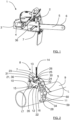
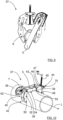
- Figure 2 shows a perspective side view of a cutter clamp 8 that is attached to a pipe 9
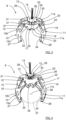
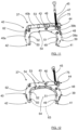
- Figure 3 shows a top perspective view of a cutter clamp 8
- Figure 4 shows a bottom perspective view of a cutter clamp 8
- Figure 5 shows a side perspective view of a cutter clamp 8 with a guide bar mounted. Due to different perspectives and levels of detailing, all Figures mentioned above do not show all details.
- the cutter clamp 8 comprises a first arcuate arm part 10 and a second arcuate arm part 11, where the arm parts 10, 11 are arcuate such that they are arranged to adjustably embrace and at least partially enclose a major part of a circumference 57 having a center 58.
- the arm parts 10, 11 comprise a corresponding first end 27, 28 and second end 29, 30, where the first ends 27, 28 are arranged to be located closer to the pipe 9 than the second ends 29, 30 when the cutter clamp 8 is attached to a pipe 9.
- the cutter clamp 8 further comprises a first intermediate part 12, a second intermediate part 13 and a locking screw 14, where the intermediate parts 12, 13 connect the arm parts 10, 11, and where the locking screw 14 runs through the intermediate parts 12, 13.
- the first intermediate part 12 is arranged to be located closer to the first ends 27, 28 than the second intermediate part 13.
- the circumference 57 and center 58 are only imaginary and are only shown in Figure 4 ; the circumference 57 can according to some aspects represent an outer circumference of a pipe.
- the arm parts 10, 11 are sandwiched between outer plates 17, 18 of the first intermediate part 12, which outer plates 17, 18 are separated in an extension L, and are connected by a first screw holder 19 that comprises a aperture 20 for receiving the and retaining an end of the locking screw 14 in a rotatable manner, and two connecting hollow rods; a first connecting hollow rod 21 and a second connecting hollow rod 22 that run mutually parallel along the extension L.
- the first arm part 10 comprises a first elongated slot 15 and the second arm part 11 comprises a second elongated slot 16, where the first hollow rod 21 runs through the first elongated slot 15 and the second hollow rod 22 runs through the second elongated slot 16.
- the arm parts 10, 11 are also sandwiched between outer plates 23, 24 of the second intermediate part 13, which outer plates 23, 24 are separated in the extension L and are connected by a second screw holder 25 and connecting rods, a first connecting rod 31 and a second connecting rod 32.
- the second screw holder 25 comprises a threaded aperture 26 for receiving the locking screw 14, and the connecting rods 31, 32 connect the arm parts 10, 11 in a pivoting manner.
- the cutter clamp 8 is arranged to contact a pipe by means of contact rods 33, 34 attached to the first ends 27, 28 of the arm parts 10, 11 and by means of a contact plate 35 connected to the outer plates 17, 18 of the first intermediate part 12.
- the chain saw 1 is arranged to be attached to the cutter clamp 8 in such a way that stable and fixed working positions are obtained, enabling a straight cut, as will be described more in detail in the following.
- the chain saw 1 comprises a mounting rod 36 that is arranged to be attached to the cutter clamp 8.
- the cutter clamp 8 is arranged for receiving the mounting rod 36 of a chain saw in one of the connecting hollow rods 21, 22, such that the mounting rod 36 runs through a connecting hollow rod 21, 22, enabling the chain saw to pivot.
- the guide bar 5 and the clutch cover 7 are shown in the Figures, not the whole chain saw 1, even if the chain saw is to be understood to be present in its entirety.
- the hollow rods 21, 22 here constitute attachment points, and in this example, as illustrated for two different pipe dimensions in Figure 6 and Figure 7 , the attachment points 21, 22 move since the hollow rods 21, 22 slide in the elongated slots 15, 16.
- the attachment points 21, 22 have been brought to a position in the elongated slots 15, 16 where the contact surface 35 is brought farther from the contact rods 33, 34 than when a smaller pipe dimension is used, as illustrated in Figure 7 .
- the attachment points 21, 22 and the contact surface 35 adjusts to the current pipe dimension in an automatic manner.
- a shorter guide bar can be used, resulting in a saw that is easier to handle and where the risk of kick-back of the guide bar is reduced, having an enhanced cutting angle.
- a shorter guide bar is enabled since the guide bar 5 always is relatively close to the pipe that is to be cut due to the fact that the attachment points 21, 22 and the contact surface 35 adjusts to the current pipe dimension as described above.
- the arcuate arm parts 10, 11 are in the above each constituted by two arm plates 10a, 10b; 11a, 11b that are separated along the extension L, as in particular shown in Figure 3 and Figure 4 , and are held in positions by means of the the contact rods 33, 34 and additional arm plate holders 59, 60 as illustrated in Figure 1 and Figure 5 .
- the arcuate arm parts may of course be made in many other ways, for example in one piece of material.
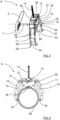
- Figure 10 shows a perspective side view of a cutter clamp 37 that is attached to a pipe 38
- Figure 11 shows a top perspective view of a cutter clamp 37
- Figure 12 shows a bottom perspective view of a cutter clamp 37
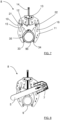
- Figure 13 shows a side perspective view of a cutter clamp 37 with a guide bar mounted. Due to different perspectives and levels of detailing, all Figures mentioned above do not show all details.
- the cutter clamp 37 comprises a first arcuate arm part 39, a second arcuate arm part 40 and a locking screw 45, where the arm parts 39, 40 are arcuate such that they are arranged to adjustably embrace and at least partially enclose a major part of a circumference 63 having a center 64.
- the arm parts 39, 40 comprise a corresponding first end 41, 42 and second end 43, 44, where a first arm second end 43 is attached to the second arm 40 in a pivoting manner by means of an arm attachment rod 53 between a second arm first end 42 and a second arm second end 44.
- the second arm part 40 comprises a first screw holder in the form of a pivoting rod 46 that in turn comprises a threaded aperture 47 arranged for receiving the locking screw 45, where the pivoting rod 46 is positioned between the first arm second end 43 and the second arm second end 44.
- the first arm part 39 comprises a hollow pivoting rod 48 that in turn is attached to a second screw holder 61 adapted for receiving and retaining an end of the locking screw 45 in a rotatable manner.
- the circumference 63 and center 64 are only imaginary and are only shown in Figure 12 ; the circumference 63 can according to some aspects represent an outer circumference of a pipe.
- the cutter clamp 37 is arranged to contact a pipe by means of outer contact rods 49, 50 attached to the first ends 41, 42 of the arm parts 39, 40, or intermediate contact rods 51, 52.
- the intermediate contact rods 51, 52 are attached between the first ends 41, 42 of the arm parts 39, 40 and the arm attachment rod 53.
- the cutter clamp 37 is according to some aspects arranged to contact a pipe by means of means of contact teeth 54 comprised in the second arm part 40.
- the second arm part 40 comprises a hollow rod 62 that runs parallel to the hollow pivoting rod 48 of the first arm part 39, both hollow rods extending along the extension L.
- the cutter clamp 37 is in accordance with the present disclosure arranged for receiving the mounting rod 36 of a chain saw in one of the hollow rods 48, 62, such that the mounting rod 36 runs through a hollow rod 48, 62, enabling the guide bar 5 to pivot.
- the guide bar 5 and the clutch cover 7 are shown, not the whole chain saw 1, even if the chain saw is to be understood to be present in its entirety.
- the the hollow rods 48, 62 here constitute attachment points, and in this example, as discussed above, the attachment points 48, 62 move since the arm parts 39, 40 are tightened against each other for the first direction of rotation of the locking screw 45.
- Each hollow rod 48, 62 moves relative the opposite arm part 39, 40 when the arms parts 39, 40 are adjusted.
- the arcuate arm parts 39, 40 are in the above each constituted by two arm plates 39a, 39b; 40a, 40b that are separated along the extension L, as in particular shown in Figure 11 and Figure 13 , and are held in positions by means of the the contact rods 49, 50; 51, 52 and additional arm plate holders 65, 66, 67 as illustrated in Figure 13 .
- the arcuate arm parts may of course be made in many other ways, for example in one piece of material.
- the cutter clamp 8, 37 comprises a first arm part 10, 39 and a second arm part 11, 40, where the arm parts 10, 11; 39 40 are arcuate and arranged to adjustably at least partially enclose a major part of a circumference 57, 63 having a center 58, 64.
- the adjustment of the arms is performed by means of a locking screw 14, 45.
- the cutter clamp 8, 37 comprises two hollow rods 21, 22; 48, 62, one arranged at each arm part 10, 11; 39, 40, where the hollow rods 21, 22; 48, 62 are arranged for receiving a mounting rod 36 of a power cutter in a pivoting manner.
- the cutter clamp has been shown to comprise two hollow rods 21, 22; 48, 62, but of course there may be only one such hollow rod arranged at one of the arcuate arms, or even more.
- the mounting rod 36 is attached to a rod attachment device 68 which in turn comprises a first leg part 69 and a second leg part 70 which are separated by an intermediate part 74.
- the clutch cover 7a here comprises a first indentation 71 and a second indentation 72, her in the form of millings, where the indentations 71, 72 are positioned on opposite sides of the clutch cover 7a and are adapted to receive the corresponding leg parts 69, 70 when these are slid into the indentations 71, 72 along a mounting direction 73.
- leg parts 69, 70 have a tight fitting in the indentations 71, 72
- the attachment device 68 can be rigidly fastened to the clutch cover 7a as shown in Figure 20 .
- the leg parts 69, 70 are shown to be of different lengths along the mounting direction 73, where the indentations 71, 72 suitably have corresponding lengths.
- the lengths of the leg parts 69, 70 can of course have any suitable relations, according to some aspects the leg parts 69, 70 have the same length.
- the rod attachment device 68 is according to some aspects suitable for attaching other types of mounting rods, or any types of suitable mounting parts, to a power cutter.
- the rod attachment device 68 is therefore generally constituted by an attachment device 68, and suitable mounting parts are according to some aspects adapted to be fastened to a wall-mounted saw holder.
- Each indentations 71, 72 is according to some aspects constituted by any form of suitable leg holding arrangement. Screws, spring-loaded balls or similar are according to some aspects arranged in at least one leg holding arrangement for securing the corresponding leg part.
- a cutter clamp according to the present disclosure can also be used for a ring saw 56.
- a holding frame 76 according to a first example is attached to the ring saw 56.
- the holding frame 76 comprises a first leg part 81 and a second leg part 82 which are separated by an intermediate part 83.
- the leg parts 81, 82 are fastened to the ring saw 56 by means of suitable fastening means 84 on opposite sides of the ring saw 56 with respect to a cutting plane of a ring saw blade 85.
- the holding frame 76 comprises an attachment flange 78 that is attached to the first leg part 81 and is arranged for releasably attaching a mounting rod 77 to the holding frame 76.
- the mounting rod 77 is in turn adapted to be received by a hollow rod 21, 22; 48, 62 of a cutter clamp 8, 37 according to the above.
- the mounting rod 77 has a treaded end 79, and the attachment flange 78 comprises corresponding inner threads 80.
- Other types of attachments are also conceivable, such as for example welding, press-fit or one or more spring-loaded balls.
- the attachment flange 78 of the holding frame 76 is according to some aspects releasably attachable to other items, such as a previously known wall-mounted saw holding device.
- FIG. 22 there is an alternative holding frame 76a according to a second example where a mounting rod 77a is directly attached to the first leg part 81 in a fixed manner.
- the mounting rod 77a is according to some aspects comprised in an extended intermediate part 83 that protrudes via the first leg part 81.
- the second arm part 40 of the cutter clamp 37 comprises a further hollow rod 75 positioned between the first screw holder 46 and the second arm second end 44.
- This further hollow rod 75 can also be adapted for receiving a mounting rod 36 of a power cutter in a pivoting manner.
- This further hollow rod 75 is especially suitable for receiving a mounting rod of a ring saw according to the above.
- Such a cutter clamp is evidently versatile and possible to use for different types of power cutters.
- an alternative cutter clamp 37' is shown.
- alternative arm parts 39', 40' are shown, where only the hollow rod 75 is comprised in the cutter clamp 37'.
- No other hollow rod that is adapted for receiving a mounting rod 36 of a power cutter in a pivoting manner is comprised in the cutter clamp 37'.
- This cutter clamp 37' is especially suitable for a ring saw according to the above.
- the cutter clamp 37' comprises a locking screw 45 that is rotatably attached to a first screw holder 46 and is arranged to engage threads comprised in a second screw holder 61' such that turning the locking screw enables the adjustment of the arm parts 39', 40'.
- the arm parts 39', 40' comprise a corresponding first end 41', 42' and second end 43', 44', where a first arm second end 43' is attached to the second arm 40' in a pivoting manner by means of an arm attachment rod 53 between a second arm first end 42' and a second arm second end 44'.
- the hollow rod 75 is positioned between the first screw holder 46 and the second arm second end 44'.
- the second screw holder 61' is concealed in Figure 23 , see the second screw holder 61 in Figure 13 for an example of the second screw holder 61' in this example. Since there is no hollow pivoting rod to which the second screw holder 61' is attached, other means are conceivable for attaching the second screw holder 61'.
- an attachment rod 86 is shown to be comprised in the first arm part 39' and adapted for being attached to the second screw holder 61' in a manner similar to the one described with reference to Figure 13 , but other alternatives are of course conceivable.
- an alternative cutter clamp 37" is shown.
- an alternative second arm part 40" is shown without contact teeth.
- the cutter clamp 8, 37 is not only suitable for a chain saw or ring saw, but also other types of power cutters that are suitable for cutting pipes are suitable for attachment to a cutter clamp 8, 37 according to the present disclosure.
- the same cutter clamp 8, 37 can according to some aspects be used for both a chain saw and a ring saw 56 as well as for other types of power cutters.
- the cutter clamp 8, 37 may be made in any suitable material, where the arm parts for example can be made of metal plates, molded metal or molded plastic.
- the intermediate parts 12, 13 that connect the arm parts 10, 11 in the first example can be formed in many ways, there do not to have to be any outer plates.
- one intermediate part 12 comprises the first screw holder 19 and the hollow rods 21, 22, while the other intermediate part 13 comprises the second screw holder 25.
- the hollow rods 21, 22 move relative the rest of the cutter clamp 8 and the pipe 9 that is to be retained by means of the elongated slots 15, 16 formed in the arm parts.
- the cutter clamps 8, 37, 37', 37" described are not only suitable when cutting through pipes, but many other items can easily be cut with the help of a cutter clamp 8, 37, 37', 37" according to the present disclosure.
- the chain saw 1 comprises a motor 2 which can be constituted by a combustion engine or an electric motor.
Landscapes
- Engineering & Computer Science (AREA)
- Mechanical Engineering (AREA)
- Life Sciences & Earth Sciences (AREA)
- Physics & Mathematics (AREA)
- Optics & Photonics (AREA)
- Wood Science & Technology (AREA)
- Forests & Forestry (AREA)
- Mining & Mineral Resources (AREA)
- Sawing (AREA)
Description
- The present disclosure relates to cutter clamps that comprise a first arm part and a second arm part, where the arm parts are arcuate and arranged to adjustably at least partially enclose a major part of a circumference having a center. The cutter clamps comprise at least one hollow rod arranged for receiving a mounting rod of a power cutter in a pivoting manner.
- The present disclosure also relates to a cutter clamp kit and cutter clamp and holding frame systems.
- When a pipe or similar is to be cut, for example during construction or due to a water leak, a cutting fixture in the form of a cutter clamp is mounted to the pipe and is connected to a power cutter, for example a suitable chain saw. The cutter clamp is normally in the form of a claw arrangement with a three-point grip that is mounted such that it partly circumvents the pipe to which it is mounted. The power cutter is then connected to the cutting fixture such that it is held in a pivoting manner, for example as described in
US 20150040736 . This results in stable and fixed working positions and provides a straight cut. - Document
CN 101 758 294 B discloses a cutter clamp that comprises a first arm part and a second arm part, where the arm parts are arcuate and arranged to adjustably at least partially enclose a major part of a circumference having a center, where the cutter clamp comprises at least one rod arranged for receiving a mounting hollow cylinder of a power cutter in a pivoting manner, the arm parts comprise a corresponding first end and second end, where a first arm second end is attached to the second arm in a pivoting manner by means of an arm attachment rod between a second arm first end and a second arm second end, where the second arm part comprises a first screw holder in the form of a pivoting rod positioned between the first arm second end and the second arm second end. - It is therefore desired to provide a cutter clamp that decreases the risk of kick-back of the guide bar, and which enables the use of a power cutter with a smaller guide bar.
- It is also desired to provide a cutter clamp that is versatile and possible to use for different types of power cutters.
- It is also desired to provide suitable means for attaching a cutter clamp to a power cutter.
- It is an object of the present disclosure to provide a cutter clamp that prevents kick-back of the guide bar, and which enables the use of a power cutter with a smaller guide bar.
- This object is achieved by means of a cutter clamp defined by the features of
claim 1. - This provides an advantage related to that a shorter guide bar can be used, resulting in a saw that is easier to handle and where the risk of kick-back of the guide bar is reduced, also enabling an enhanced cutting angle.
- According to some aspects, the cutter clamp comprises a locking screw that is rotatably attached to a first screw holder and is arranged to engage threads comprised in a second screw holder such that turning the locking screw enables the adjustment of the arm parts.
- This provides an advantage related to that the cutter clamp can be easily adjusted. According to some aspects, the cutter clamp comprises a first intermediate part and a second intermediate part, where the intermediate parts connect the arm parts. The locking screw at least partly runs via the intermediate parts.
- This provides an advantage related to that the locking screw runs in a rigid manner such that a secure clamping of a pipe can be obtained.
- According to some aspects, when the arm parts are adjusted, each hollow rod moves relative the rest of the cutter clamp by sliding in a corresponding elongated slot formed in a corresponding arm part.
- This provides an advantage related to that a symmetrical clamping arrangement is provided.
- According to some aspects, the arm parts comprise a corresponding first end and second end, where a first arm second end is attached to the second arm in a pivoting manner by means of an arm attachment rod between a second arm first end and a second arm second end.
- This provides an advantage related to that an uncomplicated cutter clamp is provided.
- It is also an object of the present disclosure to provide a cutter clamp that is versatile and possible to use for different types of power cutters.
- This object is achieved by means of a cutter clamp that comprises a first arm part and a second arm part, where the arm parts are arcuate and arranged to adjustably at least partially enclose a major part of a circumference having a center. The cutter clamp comprises one hollow rod arranged for receiving a mounting rod of a power cutter in a pivoting manner. The cutter clamp comprises a locking screw that is rotatably attached to a first screw holder and is arranged to engage threads comprised in a second screw holder such that turning the locking screw enables the adjustment of the arm parts. The arm parts comprise a corresponding first end and second end, where a first arm second end is attached to the second arm in a pivoting manner by means of an arm attachment rod between a second arm first end and a second arm second end. The hollow rod is positioned between the first screw holder and the second arm second end.
- This provides an advantage related to that a cutter clamp that is versatile and possible to use for different types of power cutters, such as a ring saw, is provided. According to some aspects, the second arm part comprises the first screw holder positioned between the first arm second end and the second arm second end, where the first arm part comprises an attachment rod that is attached to the second screw holder.
- This provides an advantage related to that the locking screw runs in a rigid manner such that a secure clamping of a pipe can be obtained.
- It is also an object of the present disclosure to provide suitable means for attaching a cutter clamp to a power cutter.
- This object is also achieved by means of a cutter clamp kit according to
claim 12, that comprises a cutter clamp and a power transfer cover. - This object is also achieved by means of a cutter clamp and holding frame system according to
claim 14. - This provides an advantage related to that an uncomplicated and easily attachable means for attaching a cutter clamp to a ring saw is provided. The holding frame is versatile since the mounting rod is releasably attachable.
- This object is also achieved by means of a cutter clamp and holding frame system according to
claim 16 - This provides an advantage related to that an uncomplicated and easily attachable means for attaching a cutter clamp to a ring saw is provided. The holding frame is rigid since the mounting rod is mounted to the first leg part in a fixed manner.
- The present disclosure will now be described more in detail with reference to the accompanying figures wherein:
- Figure 1
- shows a perspective view of a chain saw;
- Figure 2
- shows a perspective side view of a cutter clamp according to a first example that is attached to a pipe;
- Figure 3
- shows a top perspective view of a cutter clamp according to a first example;
- Figure 4
- shows bottom perspective view of a cutter clamp according to a first example;
- Figure 5
- shows side perspective view of a cutter clamp according to a first example with a guide bar mounted;
- Figure 6
- shows a front view of a cutter clamp according to a first example that is adapted for a first pipe dimension;
- Figure 7
- shows a front view of a cutter clamp according to a first example that is adapted for a second pipe dimension;
- Figure 8
- shows a front view of a cutter clamp according to a first example where a mounted guide bar is pivoted in a first position;
- Figure 9
- shows a front view of a cutter clamp according to a first example where a mounted guide bar is pivoted in a second position;
- Figure 10
- shows a perspective side view of a cutter clamp according to a second example that is attached to a pipe;
- Figure 11
- shows a top perspective view of a cutter clamp according to a second example;
- Figure 12
- shows bottom perspective view of a cutter clamp according to a second example;
- Figure 13
- shows side perspective view of a cutter clamp according to a second example with a guide bar mounted;
- Figure 14
- shows a front view of a cutter clamp according to a second example that is adapted for a first pipe dimension;
- Figure 15
- shows a front view of a cutter clamp according to a second example that is adapted for a second pipe dimension;
- Figure 16
- shows a front view of a cutter clamp according to a second example where a mounted guide bar is pivoted in a first position;
- Figure 17
- shows a front view of a cutter clamp according to a second example where a mounted guide bar is pivoted in a second position;
- Figure 18
- shows a schematic perspective view of an attachment device that is about to be mounted to a clutch cover;
- Figure 19
- shows a schematic perspective view of an attachment device that is mounted to a clutch cover;
- Figure 20
- shows a schematic perspective view of an attachment device that is about to be mounted to a clutch cover according to an alternative:
- Figure 21
- shows a perspective view of a holding frame, according to first example, that is attached to a ring saw;
- Figure 22
- shows a perspective view of a holding frame, according to second example, that is attached to a ring saw;
- Figure 23
- shows a top perspective view of a cutter clamp with only one hollow rod; and
- Figure 24
- shows a top perspective view of a cutter clamp without contact teeth.
- As shown in
Figure 1 , there is power cutter, here in the form of achain saw 1, that comprises amotor 2, ahandle 3 with apower control 4, aguide bar 5 with asaw chain 6 and aclutch cover 7 that is arranged to cover a power transferring arrangement that is adapted to transfer power from themotor 2 to thesaw chain 6, suitably in the form of a clutch and a transmission. - With reference to
Figure 2 ,Figure 3 ,Figure 4 andFigure 5 , a first example of a cutter clamp will be described.Figure 2 shows a perspective side view of acutter clamp 8 that is attached to apipe 9,Figure 3 shows a top perspective view of acutter clamp 8,Figure 4 shows a bottom perspective view of acutter clamp 8, andFigure 5 shows a side perspective view of acutter clamp 8 with a guide bar mounted. Due to different perspectives and levels of detailing, all Figures mentioned above do not show all details. - The
cutter clamp 8 comprises a firstarcuate arm part 10 and a secondarcuate arm part 11, where thearm parts circumference 57 having acenter 58. Thearm parts first end second end pipe 9 than the second ends 29, 30 when thecutter clamp 8 is attached to apipe 9. Thecutter clamp 8 further comprises a firstintermediate part 12, a secondintermediate part 13 and a lockingscrew 14, where theintermediate parts arm parts screw 14 runs through theintermediate parts intermediate part 12 is arranged to be located closer to the first ends 27, 28 than the secondintermediate part 13. Thecircumference 57 andcenter 58 are only imaginary and are only shown inFigure 4 ; thecircumference 57 can according to some aspects represent an outer circumference of a pipe. - The
arm parts outer plates intermediate part 12, whichouter plates first screw holder 19 that comprises aaperture 20 for receiving the and retaining an end of the lockingscrew 14 in a rotatable manner, and two connecting hollow rods; a first connectinghollow rod 21 and a second connectinghollow rod 22 that run mutually parallel along the extension L. Thefirst arm part 10 comprises a firstelongated slot 15 and thesecond arm part 11 comprises a secondelongated slot 16, where the firsthollow rod 21 runs through the firstelongated slot 15 and the secondhollow rod 22 runs through the secondelongated slot 16. When apipe 9 is attached to thecutter clamp 8, it has a longitudinal extension that coincides with the extension L. - The
arm parts outer plates intermediate part 13, whichouter plates second screw holder 25 and connecting rods, a first connectingrod 31 and a second connectingrod 32. Thesecond screw holder 25 comprises a threadedaperture 26 for receiving the lockingscrew 14, and the connectingrods arm parts - The
cutter clamp 8 is arranged to contact a pipe by means ofcontact rods arm parts contact plate 35 connected to theouter plates intermediate part 12. When the lockingscrew 14 is rotated, the end that is retained in thefirst screw holder 19 rotates and is moved towards or away from thesecond screw holder 25 since the lockingscrew 14 engages threads in the threadedaperture 26. This means that the end that is retained in thefirst screw holder 19 is rotatably secured to thefirst screw holder 19, such that the relative position of the lockingscrew 14 and thescrew holder 19 is maintained upon rotation of the screw. - In this manner, with reference also to
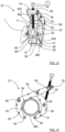
Figure 6 andFigure 7 showing thecutter clamp 8 adapted for twodifferent pipe dimensions 9a, 9b, for a first direction of rotation of the lockingscrew 14, thecontact surface 35 is brought closer to thecontact rods hollow rods elongated slots intermediate part 13. For an opposite second direction of rotation of the lockingscrew 14, thecontact surface 35 is brought away from thecontact rods contact rods hollow rods elongated slots intermediate part 13. For the first direction of rotation, if apipe cutter clamp 8, thecontact surface 35 and thecontact rods pipe pipe - The chain saw 1 is arranged to be attached to the
cutter clamp 8 in such a way that stable and fixed working positions are obtained, enabling a straight cut, as will be described more in detail in the following. For this purpose, the chain saw 1 comprises a mountingrod 36 that is arranged to be attached to thecutter clamp 8. - According to the present disclosure, in particular as shown in
Figure 2 and alsoFigure 5 , thecutter clamp 8 is arranged for receiving the mountingrod 36 of a chain saw in one of the connectinghollow rods rod 36 runs through a connectinghollow rod Figure 1 , only theguide bar 5 and theclutch cover 7 are shown in the Figures, not the whole chain saw 1, even if the chain saw is to be understood to be present in its entirety. - The
hollow rods Figure 6 andFigure 7 , the attachment points 21, 22 move since thehollow rods elongated slots contact surface 35 and the attachment points are brought to thecontact rods elongated slots Figure 6 , the attachment points 21, 22 have been brought to a position in theelongated slots contact surface 35 is brought farther from thecontact rods Figure 7 . By sliding in theelongated slots cutter clamp 8 is tightened against the current pipe, the attachment points 21, 22 and thecontact surface 35 adjusts to the current pipe dimension in an automatic manner. - When the chain saw 1 is attached to the
cutter clamp 8, theguide bar 5 and thus the whole chain saw 1 can be pivoted such that it cuts thepipe 9 in a desired manner as shown inFigure 8 andFigure 9 . - By means of the present disclosure, a shorter guide bar can be used, resulting in a saw that is easier to handle and where the risk of kick-back of the guide bar is reduced, having an enhanced cutting angle. A shorter guide bar is enabled since the
guide bar 5 always is relatively close to the pipe that is to be cut due to the fact that the attachment points 21, 22 and thecontact surface 35 adjusts to the current pipe dimension as described above. - The
arcuate arm parts arm plates Figure 3 and Figure 4 , and are held in positions by means of the thecontact rods arm plate holders Figure 1 andFigure 5 . The arcuate arm parts may of course be made in many other ways, for example in one piece of material. - With reference to
Figure 1 ,Figure 10 ,Figure 11, Figure 12 andFigure 13 , a second example of a cutter clamp will be described.Figure 10 shows a perspective side view of acutter clamp 37 that is attached to apipe 38,Figure 11 shows a top perspective view of acutter clamp 37,Figure 12 shows a bottom perspective view of acutter clamp 37 andFigure 13 shows a side perspective view of acutter clamp 37 with a guide bar mounted. Due to different perspectives and levels of detailing, all Figures mentioned above do not show all details. - The
cutter clamp 37 comprises a firstarcuate arm part 39, a secondarcuate arm part 40 and a lockingscrew 45, where thearm parts circumference 63 having acenter 64. Thearm parts first end second end second end 43 is attached to thesecond arm 40 in a pivoting manner by means of anarm attachment rod 53 between a second armfirst end 42 and a second armsecond end 44. - The
second arm part 40 comprises a first screw holder in the form of a pivotingrod 46 that in turn comprises a threadedaperture 47 arranged for receiving the lockingscrew 45, where the pivotingrod 46 is positioned between the first armsecond end 43 and the second armsecond end 44. Thefirst arm part 39 comprises ahollow pivoting rod 48 that in turn is attached to asecond screw holder 61 adapted for receiving and retaining an end of the lockingscrew 45 in a rotatable manner. When apipe 38 is attached to thecutter clamp 37, it has a longitudinal extension that coincides with an extension L. - The
circumference 63 andcenter 64 are only imaginary and are only shown inFigure 12 ; thecircumference 63 can according to some aspects represent an outer circumference of a pipe. - The
cutter clamp 37 is arranged to contact a pipe by means ofouter contact rods arm parts intermediate contact rods intermediate contact rods arm parts arm attachment rod 53. Thecutter clamp 37 is according to some aspects arranged to contact a pipe by means of means ofcontact teeth 54 comprised in thesecond arm part 40. When the lockingscrew 45 is rotated, the end that is retained in thehollow pivoting rod 48 rotates and is moved towards or away from the pivotingrod 46 since the lockingscrew 45 engages threads in the threadedaperture 47. - In this manner, for a first direction of rotation of the locking
screw 45, initially theouter contact rods intermediate contact rods outer contact rod 49 is brought past a second armouter contact rod 50 and towards a second armintermediate contact rod 52. - This is illustrated for three
different pipe dimensions Figure 10 ,Figure 14 andFigure 15 . InFigure 10 , for the first direction of rotation, theouter contact rods contact teeth 54 are brought into contact with thepipe 38, holding thepipe 38. InFigure 14 , for the first direction of rotation, theintermediate contact rods contact teeth 54 are brought into contact with thepipe 38a, holding thepipe 38a. InFigure 15 , for the first direction of rotation, the first armintermediate contact rod 51, a firstarm contact surface 55 located between the first armintermediate contact rod 51 and thearm attachment rod 53, and thecontact teeth 54 are brought into contact with thepipe 38b, holding thepipe 38b, while the first armouter contact rod 49 is concealed behind thesecond arm part 40. For the second direction of rotation, a retainedpipe - As shown in detail in
Figure 15 , thesecond arm part 40 comprises ahollow rod 62 that runs parallel to thehollow pivoting rod 48 of thefirst arm part 39, both hollow rods extending along the extension L. In the same way as in the first example, thecutter clamp 37 is in accordance with the present disclosure arranged for receiving the mountingrod 36 of a chain saw in one of thehollow rods rod 36 runs through ahollow rod guide bar 5 to pivot. As for the first example, where applicable in the Figures, only theguide bar 5 and theclutch cover 7 are shown, not the whole chain saw 1, even if the chain saw is to be understood to be present in its entirety. - When the chain saw 1 is attached to the
cutter clamp 37, it can be pivoted such that it cuts the pipe in a desired manner as shown inFigure 16 andFigure 17 . - The the
hollow rods arm parts screw 45. Eachhollow rod opposite arm part arms parts center 64 when thecutter clamp 37 is tightened against the current pipe. - The
arcuate arm parts arm plates Figure 11 andFigure 13 , and are held in positions by means of the thecontact rods arm plate holders Figure 13 . The arcuate arm parts may of course be made in many other ways, for example in one piece of material. - In the above, two examples of cutter clamps 8, 37 have been presented. For both examples, the attachment points 21, 22; 48, 62 are automatically adapted to the current pipe dimension when the
cutter clamp cutter clamp first arm part second arm part arm parts circumference center screw - The
cutter clamp hollow rods arm part hollow rods rod 36 of a power cutter in a pivoting manner. The smaller circumference the arm parts are adjusted for, the closer to thecenter hollow rods hollow rods - According to some aspects, with reference to
Figure 18 andFigure 19 , the mountingrod 36 is attached to arod attachment device 68 which in turn comprises afirst leg part 69 and asecond leg part 70 which are separated by anintermediate part 74. Theclutch cover 7a here comprises afirst indentation 71 and asecond indentation 72, her in the form of millings, where theindentations clutch cover 7a and are adapted to receive thecorresponding leg parts indentations direction 73. - Since the
leg parts indentations attachment device 68 can be rigidly fastened to theclutch cover 7a as shown inFigure 20 . Theleg parts direction 73, where theindentations leg parts leg parts - The
rod attachment device 68 is according to some aspects suitable for attaching other types of mounting rods, or any types of suitable mounting parts, to a power cutter. Therod attachment device 68 is therefore generally constituted by anattachment device 68, and suitable mounting parts are according to some aspects adapted to be fastened to a wall-mounted saw holder. - An alternative is shown in
Figure 20 , where an alternativeclutch cover 7b only comprises oneindentation 72 which according to some aspects is sufficient for rigidly fastening theattachment device 68 to theclutch cover 7b. - Each
indentations - With reference to
Figure 21 , a cutter clamp according to the present disclosure can also be used for a ring saw 56. Here, a holdingframe 76 according to a first example is attached to the ring saw 56. The holdingframe 76 comprises afirst leg part 81 and asecond leg part 82 which are separated by anintermediate part 83. Theleg parts blade 85. - The holding
frame 76 comprises anattachment flange 78 that is attached to thefirst leg part 81 and is arranged for releasably attaching a mountingrod 77 to the holdingframe 76. The mountingrod 77 is in turn adapted to be received by ahollow rod cutter clamp - According to some aspects, the mounting
rod 77 has atreaded end 79, and theattachment flange 78 comprises correspondinginner threads 80. Other types of attachments are also conceivable, such as for example welding, press-fit or one or more spring-loaded balls. - The
attachment flange 78 of the holdingframe 76 is according to some aspects releasably attachable to other items, such as a previously known wall-mounted saw holding device. - With reference to
Figure 22 , there is analternative holding frame 76a according to a second example where a mountingrod 77a is directly attached to thefirst leg part 81 in a fixed manner. The mountingrod 77a is according to some aspects comprised in an extendedintermediate part 83 that protrudes via thefirst leg part 81. - According to some aspects, with reference to
Figure 10-15 , thesecond arm part 40 of thecutter clamp 37 according to the second example comprises a furtherhollow rod 75 positioned between thefirst screw holder 46 and the second armsecond end 44. This furtherhollow rod 75 can also be adapted for receiving a mountingrod 36 of a power cutter in a pivoting manner. This furtherhollow rod 75 is especially suitable for receiving a mounting rod of a ring saw according to the above. Such a cutter clamp is evidently versatile and possible to use for different types of power cutters. - According to some aspects with reference to
Figure 23 , which corresponds toFigure 11 , an alternative cutter clamp 37' is shown. Here,alternative arm parts 39', 40' are shown, where only thehollow rod 75 is comprised in the cutter clamp 37'. No other hollow rod that is adapted for receiving a mountingrod 36 of a power cutter in a pivoting manner is comprised in the cutter clamp 37'. This cutter clamp 37' is especially suitable for a ring saw according to the above. - The cutter clamp 37' comprises a locking
screw 45 that is rotatably attached to afirst screw holder 46 and is arranged to engage threads comprised in a second screw holder 61' such that turning the locking screw enables the adjustment of thearm parts 39', 40'. Thearm parts 39', 40' comprise a corresponding first end 41', 42' and second end 43', 44', where a first arm second end 43' is attached to thesecond arm 40' in a pivoting manner by means of anarm attachment rod 53 between a second arm first end 42' and a second arm second end 44'. Thehollow rod 75 is positioned between thefirst screw holder 46 and the second arm second end 44'. - The second screw holder 61' is concealed in
Figure 23 , see thesecond screw holder 61 inFigure 13 for an example of the second screw holder 61' in this example. Since there is no hollow pivoting rod to which the second screw holder 61' is attached, other means are conceivable for attaching the second screw holder 61'. InFigure 23 , anattachment rod 86 is shown to be comprised in the first arm part 39' and adapted for being attached to the second screw holder 61' in a manner similar to the one described with reference toFigure 13 , but other alternatives are of course conceivable. - According to some aspects with reference to
Figure 24 , which corresponds toFigure 11 , analternative cutter clamp 37" is shown. Here, an alternativesecond arm part 40" is shown without contact teeth. - The alternatives and alternative cutter clamps 37, 37', 37" disclosed can naturally be combined in any suitable manner falling within the scope of the claims.
- The present disclosure is not limited to the examples described above, but may vary freely within the scope of the appended claims. For example, the
cutter clamp cutter clamp same cutter clamp - In this context, expressions such as parallel are not intended to be interpreted as mathematically exact, but within what normally is practically obtainable.
- The
cutter clamp - According to some aspects, the
intermediate parts arm parts intermediate part 12 comprises thefirst screw holder 19 and thehollow rods intermediate part 13 comprises thesecond screw holder 25. For the first example, thehollow rods cutter clamp 8 and thepipe 9 that is to be retained by means of theelongated slots - The cutter clamps 8, 37, 37', 37" described are not only suitable when cutting through pipes, but many other items can easily be cut with the help of a
cutter clamp - The chain saw 1 comprises a
motor 2 which can be constituted by a combustion engine or an electric motor. - Depending on the type of power cutter and type of motor, there may not be any clutch comprised in the power transferring arrangement. There is normally always some kind of transmission means for transferring power from the
motor 2 to thesaw chain 6 or sawblade 85, and generally the clutch covers described are constituted by a power transfer cover.
Claims (16)
- A cutter clamp (37, 37', 37") that comprises a first arm part (39, 39') and a second arm part (40, 40', 40"), where the arm parts (39, 40; 39', 40', 40") are arcuate and arranged to adjustably at least partially enclose a major part of a circumference (63) having a center (64), where the cutter clamp (37, 37', 37") comprises at least one hollow rod (48, 62, 75) arranged for receiving a mounting rod (36, 77, 77a) of a power cutter (1, 56) in a pivoting manner, the arm parts (39, 40, 39', 40', 40") comprise a corresponding first end (41, 42, 41', 42') and second end (43, 44, 43', 44'), where a first arm second end (43, 43') is attached to the second arm (40, 40', 40") in a pivoting manner by means of an arm attachment rod (53) between a second arm first end (42, 42') and a second arm second end (44, 44'), where the second arm part (40, 40', 40") comprises a first screw holder in the form of a pivoting rod (46) positioned between the first arm second end (43, 43') and the second arm second end (44, 44'), wherein- the smaller circumference the arm parts (39, 40, 40") are adjusted for, the closer to the center (64) said hollow rod (48, 62) is moved, and the second arm part (40, 40', 40") comprises a further hollow rod (75) positioned between the first screw holder (46) and the second arm second end (44, 44'), or- the second arm part (40, 40', 40") comprises only a hollow rod (75) positioned between the first screw holder (46) and the second arm second end (44, 44').
- A cutter clamp (37, 37', 37") according to any one of the previous claims, wherein the cutter clamp (37, 37') comprises a locking screw (45) that is rotatably attached to the first screw holder (46) and is arranged to engage threads comprised in a second screw holder (61, 61') such that turning the locking screw enables the adjustment of the arm parts (39, 40; 39', 40').
- A cutter clamp (37, 37") according to claim 2, wherein the second arm part (40, 40") comprises the first screw holder (46) positioned between the first arm second end (43) and the second arm second end (44), where the first arm part (39) comprises a hollow pivoting rod (48) that in turn is attached to the second screw holder (61).
- A cutter clamp (37, 37") according to claim 3, wherein each hollow rod (48, 62) is attached to a corresponding arm part (39, 40, 40"), such when the arm parts (39, 40, 40") are adjusted, said hollow rod (48, 62) moves relative the opposite arm part (39, 40, 40").
- A cutter clamp (37, 37', 37") according to any one of the previous claims, wherein the second arm part (40, 40', 40") comprises a further hollow rod (75) positioned between the first screw holder (46) and the second arm second end (44, 44').
- A cutter clamp (37, 37', 37") that comprises a first arm part (39, 39') and a second arm part (40, 40', 40"), where the arm parts (39, 40; 39', 40', 40") are arcuate and arranged to adjustably at least partially enclose a major part of a circumference (63) having a center (64), where the cutter clamp (37, 37', 37") comprises one hollow rod (75) arranged for receiving a mounting rod (36) of a power cutter (1, 56) in a pivoting manner, wherein the cutter clamp (37, 37', 37") comprises a locking screw (45) that is rotatably attached to a first screw holder (46) and is arranged to engage threads comprised in a second screw holder (61, 61') such that turning the locking screw enables the adjustment of the arm parts (39, 40; 39', 40', 40"), where the arm parts (39, 40; 39', 40', 40") comprise a corresponding first end (41, 42; 41', 42') and second end (43, 44; 43', 44'), where a first arm second end (43, 43') is attached to the second arm (40, 40') in a pivoting manner by means of an arm attachment rod (53) between a second arm first end (42, 42') and a second arm second end (44, 44'), where the hollow rod (75) is positioned between the first screw holder (46) and the second arm second end (44, 44').
- A cutter clamp (37') according to claim 6, wherein the second arm part (40') comprises the first screw holder (46') positioned between the first arm second end (43') and the second arm second end (44'), where the first arm part (39') comprises an attachment rod (86) that is attached to the second screw holder (61').
- A cutter clamp (37, 37') according to any one of the claims 6 or 7, wherein the second arm part (40, 40') comprises contact teeth (54) arranged to contact a pipe.
- A cutter clamp (8) that comprises a first arm part (10) and a second arm part (11), where the arm parts (10, 11) are arcuate and arranged to adjustably at least partially enclose a major part of a circumference (57) having a center (58), where the cutter clamp (8) comprises at least one hollow rod (21, 22) arranged for receiving a mounting rod (36) of for a power cutter (1, 56) in a pivoting manner, wherein the smaller circumference the arm parts (10, 11) are adjusted for, the closer to the center (58) said hollow rod (21, 22) is moved, where the cutter clamp (8) comprises a first intermediate part (12) and a second intermediate part (13), where the intermediate parts (12, 13) connect the arm parts (10, 11), and where a locking screw (14) at least partly runs via the intermediate parts (12, 13), and when the arm parts (10, 11) are adjusted, each hollow rod (21, 22) moves relative the arm parts (10, 11) by sliding in a corresponding elongated slot (15, 16) formed in a corresponding arm part (10, 11).
- A cutter clamp (8) according to claim 9, wherein the cutter clamp (8) comprises a locking screw (14) that is rotatably attached to a first screw holder (19) and is arranged to engage threads comprised in a second screw holder (25) such that turning the locking screw enables the adjustment of the arm parts (10, 11).
- A cutter clamp (8) according to claim 10, wherein one intermediate part (12) comprises the first screw holder (19) and said hollow rod (21, 22), while the other intermediate part (13) comprises the second screw holder (25).
- A cutter clamp kit, wherein the cutter clamp kit comprises a cutter clamp (8, 37, 37', 37") according to any one of the claims 1-12, a power transfer cover (7a, 7b) and an attachment device (68) adapted for attaching a mounting part (36) to a power transfer cover (7a, 7b) for a power cutter (1), where the attachment device (68) comprises a first leg part (69) and a second leg part (70), which leg parts (69, 70) are separated by an intermediate part (74), where the mounting part (36) is attached to the first leg part (69), where furthermore the leg parts (69, 70) are adapted to be positioned on opposite sides of the power transfer cover (7a, 7b) such that at least one leg part (69, 70) is received and retained by a corresponding leg holding arrangement (71, 72).
- A cutter clamp kit according to claim 12, wherein the mounting part (36) is constituted by a mounting rod that is adapted to be connected to a cutter clamp (8, 37, 37', 37") according to any one of the claims 1-12.
- A cutter clamp and holding frame system comprising a cutter clamp (8, 37, 37', 37") according to any one of the claims 1-11 and a holding frame (76) adapted to be attached to a ring saw (56), wherein the holding frame (76) comprises a first leg part (81) and a second leg part (82), which leg parts (81, 82) are separated by an intermediate part (83), where the leg parts (81, 82) are adapted to be fastened to a ring saw (56) on opposite sides of the ring saw (56) with respect to a cutting plane of a ring saw blade (85), where the holding frame (76) comprises an attachment flange (78) that is attached to the first leg part (81), where the attachment flange (78) is arranged to be releasably attached to a mounting rod (77) that is adapted to be connected to the cutter clamp (8, 37, 37', 37").
- A cutter clamp and holding frame system according to claim 14, wherein the mounting rod (77) has a threaded end (79), and the attachment flange (78) comprises corresponding inner threads (80).
- A cutter clamp and holding frame system comprising a cutter clamp (8, 37, 37', 37") according to any one of the claims 1-11 and a holding frame (76a) adapted to be attached to a ring saw (56), wherein the holding frame (76a) comprises a first leg part (81) and a second leg part (82), which leg parts (81, 82) are separated by an intermediate part (83), where the leg parts (81, 82) are adapted to be fastened to a ring saw (56) on opposite sides of the ring saw (56) with respect to a cutting plane of a ring saw blade (85), where the holding frame (76a) comprises a mounting rod (77a) that is directly attached to the first leg part (81) in a fixed manner, where the mounting rod (77a) is adapted to be connected to the cutter clamp (8, 37, 37', 37").
Applications Claiming Priority (2)
| Application Number | Priority Date | Filing Date | Title |
|---|---|---|---|
| SE1751027A SE541669C2 (en) | 2017-08-28 | 2017-08-28 | A cutter clamp |
| PCT/SE2018/050449 WO2019045614A1 (en) | 2017-08-28 | 2018-05-02 | A cutter clamp, an attachment device, a cutter clamp kit and a holding frame |
Publications (3)
| Publication Number | Publication Date |
|---|---|
| EP3676037A1 EP3676037A1 (en) | 2020-07-08 |
| EP3676037A4 EP3676037A4 (en) | 2021-08-04 |
| EP3676037B1 true EP3676037B1 (en) | 2024-10-02 |
Family
ID=65525799
Family Applications (1)
| Application Number | Title | Priority Date | Filing Date |
|---|---|---|---|
| EP18851371.7A Active EP3676037B1 (en) | 2017-08-28 | 2018-05-02 | Cutter clamps, cutter clamp kit, and cutter clamp and holding frame systems |
Country Status (4)
| Country | Link |
|---|---|
| US (1) | US11305405B2 (en) |
| EP (1) | EP3676037B1 (en) |
| SE (1) | SE541669C2 (en) |
| WO (1) | WO2019045614A1 (en) |
Families Citing this family (11)
| Publication number | Priority date | Publication date | Assignee | Title |
|---|---|---|---|---|
| SE541669C2 (en) * | 2017-08-28 | 2019-11-26 | Husqvarna Ab | A cutter clamp |
| CN110315126B (en) * | 2019-06-25 | 2020-06-26 | 湖州银都铝业有限公司 | Cutting machine is used in aluminium alloy preparation |
| CN110450116B (en) * | 2019-07-10 | 2020-12-11 | 浙江海州宝实业有限公司 | A clamping table for metal pipe processing |
| DE102019121096A1 (en) * | 2019-08-05 | 2021-02-11 | Mafell Ag | Portable clamping device and power tool with integrated workpiece fixation |
| CN111604541B (en) * | 2020-04-30 | 2021-05-14 | 张家港幸运金属工艺品有限公司 | Cutting device for metal processing |
| CN111390275A (en) * | 2020-05-11 | 2020-07-10 | 郑荣城 | High-precision aluminum profile cutting device and using method thereof |
| CN113601217B (en) * | 2021-07-20 | 2022-06-28 | 青岛理工大学 | An automobile wheel hub fixture, processing equipment and production line |
| WO2023065028A1 (en) | 2021-10-22 | 2023-04-27 | Ring Rescue Inc. | Ring cutter for safely transecting a ring trapped on an appendage |
| CN115824302A (en) * | 2022-11-30 | 2023-03-21 | 西安奕斯伟材料科技有限公司 | Single crystal transfer measuring method and system |
| USD1089340S1 (en) | 2023-06-22 | 2025-08-19 | Ring Rescue Inc. | Ring cutter |
| DE102024212301A1 (en) * | 2024-12-23 | 2026-06-25 | Robert Bosch Gesellschaft mit beschränkter Haftung | Cutting device, in particular pipe cutting device |
Family Cites Families (54)
| Publication number | Priority date | Publication date | Assignee | Title |
|---|---|---|---|---|
| US1086574A (en) | 1914-02-10 | Anton Anderson | Clamp. | |
| US1075384A (en) | 1913-05-13 | 1913-10-14 | Emil K F Seidel | Woodworking-clamp. |
| DE495132C (en) | 1929-05-02 | 1930-04-02 | Ernst A Rueeger | Transportable log and cut-off chainsaw |
| US2567833A (en) | 1948-09-04 | 1951-09-11 | Chester E Warren | Pipe cutter |
| US2890906A (en) * | 1954-08-04 | 1959-06-16 | Jones & Laughlin Steel Corp | Article lifting apparatus |
| US2870536A (en) | 1957-08-26 | 1959-01-27 | Lutsker Simon | Tubing cutter |
| FR2267418B1 (en) * | 1974-04-09 | 1976-10-08 | Mecanique Ste Turripinoise | |
| US4068415A (en) * | 1976-01-12 | 1978-01-17 | Racine Railroad Products, Inc. | Rail cutting apparatus |
| US4156991A (en) * | 1978-01-09 | 1979-06-05 | Racine Railroad Products, Inc. | Rail cutting apparatus |
| US4278246A (en) * | 1979-12-13 | 1981-07-14 | Blake John B | Clamping device |
| CH639588A5 (en) | 1980-04-09 | 1983-11-30 | Walter Oetliker | Holder for a power chain-saw with a pivotable protective hood |
| NO147370C (en) | 1981-03-26 | 1983-03-30 | Norcem As | ADDITIONAL EQUIPMENT FOR MOTOR POWERED CHAIN. |
| US4476759A (en) * | 1982-03-03 | 1984-10-16 | Aderneck Stephen E | Portable chainsaw milling guide attachment |
| DE3521697A1 (en) * | 1984-06-18 | 1986-02-20 | Tetsushi Ichihara Chiba Kubo | PIPE PROCESSING DEVICE |
| JPS6131613U (en) | 1984-07-30 | 1986-02-26 | 勝 北井 | Cutter support device |
| JPS6165718A (en) * | 1984-09-07 | 1986-04-04 | Kusumoto Kazushige | Method of severing water pipe or the like by use of cutting saw having flexible shaft |
| US4689883A (en) | 1985-11-04 | 1987-09-01 | Dent Larry G | Pipe cutting device |
| US4682919A (en) | 1986-05-05 | 1987-07-28 | Reed Manufacturing Company | Portable powered pipe working machine |
| GB8925104D0 (en) | 1989-11-07 | 1989-12-28 | British Gas Plc | Cutting apparatus |
| US5107594A (en) * | 1991-09-03 | 1992-04-28 | Julian Ferreras | Piling cutting tool |
| RU1838054C (en) | 1992-02-05 | 1993-08-30 | Mamedov Ilgam I | Pipe cutter |
| SE506306C2 (en) * | 1993-05-03 | 1997-12-01 | Electrolux Ab | Device for cutting machine or circular saw and a system with a plurality of interchangeable components |
| DE9417353U1 (en) * | 1994-10-28 | 1995-01-26 | Ludwig Hunger Maschinenfabrik GmbH, 86916 Kaufering | Clamping device |
| DE19614611C2 (en) | 1996-04-15 | 2001-01-11 | Spitznas Maschinenfabrik Gmbh | Pipe cutting device |
| FI990167A7 (en) | 1999-01-29 | 2000-07-30 | For Man Trade Oy | Device for machining or processing tubular or round bar-shaped pieces |
| FI108927B (en) | 2000-06-30 | 2002-04-30 | For Man Trade Oy | Apparatus for machining a tubular or circular bar, especially for cutting |
| EP1236551B1 (en) | 2001-03-02 | 2007-10-24 | Landrock GmbH | Device for cutting up bundled wood pieces |
| DE10229671A1 (en) | 2001-07-04 | 2003-01-23 | Klaus Fritsch | Holder for motorised saw, especially chainsaw, allows saw to be pivoted about axis located in cutting plane defined by flat extension of sword part of saw |
| US6619171B2 (en) | 2002-01-09 | 2003-09-16 | Blount, Inc. | Guide bar for tree harvesting including stump treatment |
| FI118076B (en) * | 2003-05-22 | 2007-06-29 | Exact Tools Oy | Apparatus for machining a tubular and circular bar, especially for cutting |
| US6893012B2 (en) * | 2003-05-23 | 2005-05-17 | Valtra, Inc. | Quick release cantilever clamp |
| CA2542630A1 (en) * | 2006-04-10 | 2007-10-10 | Enbridge Gas Distribution Inc. | Service tee cutting apparatus and abandonment method |
| US7703211B1 (en) * | 2007-06-04 | 2010-04-27 | Kirchhoff Robert W | Easy lift saw platform |
| AT505753B1 (en) | 2007-10-22 | 2009-04-15 | Reichart Ing Otto | MOTOR SAGE |
| DE102008025716A1 (en) * | 2008-05-29 | 2009-12-03 | Illinois Tool Works Inc., Glenview | Pipe processing device, in particular pipe separating device |
| US8651005B2 (en) * | 2008-07-09 | 2014-02-18 | Blount, Inc. | Utility chain cutter |
| CN101758294B (en) * | 2008-12-25 | 2012-03-28 | 苏州宝时得电动工具有限公司 | Reciprocating saw |
| DE202009014060U1 (en) | 2009-10-14 | 2010-02-11 | Henkel, Meinolf | chainsaw Bock |
| CN102713068B (en) * | 2009-12-03 | 2014-11-12 | 塞母布雷有限公司 | Apparatus for the tooling of a workpiece |
| DE202010008463U1 (en) | 2010-09-06 | 2011-12-07 | Industriepartners Gmbh | Device for cutting a pipe |
| US9385911B2 (en) | 2011-05-13 | 2016-07-05 | Sameer Vermani | Systems and methods for wireless communication of packets having a plurality of formats |
| FI123764B (en) | 2011-07-06 | 2013-10-31 | Exact Tools Oy | Apparatus for machining a tubular piece |
| DE102011080450A1 (en) | 2011-08-04 | 2013-02-07 | WIDOS Wilhelm Dommer Söhne GmbH | Thick walled large-volume plastic pipe cutting device for use in construction site, has saw chain rotated around strut, where strut is displaceably arranged between resting and cutting positions relative to guide carriage |
| US8720070B2 (en) | 2011-11-04 | 2014-05-13 | Reed Manufacturing Company | Pipe peeler |
| WO2013070203A2 (en) * | 2011-11-09 | 2013-05-16 | Sumner Manufacturing Co.,Inc. | Clamp assembly |
| WO2014007701A1 (en) | 2012-07-04 | 2014-01-09 | Iggesund Forest Ab | Cutting arrangement for gripping and cutting trees or bushes |
| DE102013101046A1 (en) | 2013-02-01 | 2014-08-07 | Alexander van Linn | Device for processing split log bundles for e.g. fireplace wood production for wood-burning stove, has sawing devices pivotably arranged at gripping device around pivot point, and movable by bundles, which are received by gripping device |
| FI125718B (en) | 2014-01-22 | 2016-01-29 | Exact Tools Oy | Apparatus for handling tubular or round bar-like bodies |
| DE102014006255A1 (en) | 2014-04-28 | 2015-10-29 | PF Schweißtechnologie GmbH | Processing device for pipe jacket surfaces |
| WO2016012776A1 (en) | 2014-07-22 | 2016-01-28 | Andrew Page | Tree-cutting head |
| US9724808B2 (en) * | 2016-01-05 | 2017-08-08 | William Blackford | Ergonomic front fork service tool |
| FI20165277A7 (en) * | 2016-04-01 | 2017-10-02 | Exact Tools Oy | An apparatus for supporting a tool unit for manipulating a workpiece |
| CN107052692A (en) * | 2016-12-07 | 2017-08-18 | 西北工业大学(张家港)智能装备技术产业化研究院有限公司 | Pipeline welding fixture |
| SE541669C2 (en) * | 2017-08-28 | 2019-11-26 | Husqvarna Ab | A cutter clamp |
-
2017
- 2017-08-28 SE SE1751027A patent/SE541669C2/en unknown
-
2018
- 2018-05-02 EP EP18851371.7A patent/EP3676037B1/en active Active
- 2018-05-02 WO PCT/SE2018/050449 patent/WO2019045614A1/en not_active Ceased
- 2018-05-02 US US16/640,867 patent/US11305405B2/en active Active
Also Published As
| Publication number | Publication date |
|---|---|
| US20200189070A1 (en) | 2020-06-18 |
| SE541669C2 (en) | 2019-11-26 |
| US11305405B2 (en) | 2022-04-19 |
| EP3676037A1 (en) | 2020-07-08 |
| WO2019045614A1 (en) | 2019-03-07 |
| SE1751027A1 (en) | 2019-03-01 |
| EP3676037A4 (en) | 2021-08-04 |
Similar Documents
| Publication | Publication Date | Title |
|---|---|---|
| US11305405B2 (en) | Cutter clamp, an attachment device, a cutter clamp kit and a holding frame | |
| EP2977155B1 (en) | Power tool accessory with brace | |
| US10945381B1 (en) | Modular tools with detachable coupling | |
| US5806187A (en) | Clamping device | |
| US4402136A (en) | Device for cutting pipes | |
| US5611146A (en) | Clamping device for use with a hand-held tool | |
| CA2974671C (en) | Miter saw | |
| CA2708545C (en) | Hand saw | |
| US7967666B1 (en) | Blade sharpener | |
| EP2492070A1 (en) | Chainsaw, particularly for trimming trees and bushes | |
| US2880773A (en) | Hack saw | |
| FR2964526A1 (en) | Tool carrying arm device for carrying electric, thermal or hydraulic removable tools such as hedge clipper, fixed on lawn tractor in urban place, has flanges allowing locking of frame on lawn tractor, small tractor and power lift truck | |
| US6942416B2 (en) | Device for attaching a handle | |
| KR200484399Y1 (en) | Sickle | |
| EP0032148A4 (en) | Device for cutting pipes. | |
| EP3082396B1 (en) | Handle arrangement for a power tool | |
| JP2013247888A (en) | Portable working machine | |
| CN104271297B (en) | Filing fixture | |
| US2896481A (en) | Saw sharpening apparatus | |
| EP1588817B1 (en) | Adaptation of a portable jig-saw for cutting grooves in walls | |
| US20240051044A1 (en) | Hacksaw | |
| CN105309209A (en) | Multiple-degree-of-freedom hedge trimmer | |
| US3115911A (en) | Guide apparatus for hole saws | |
| US20070130782A1 (en) | Saw alignment device, blade assembly, and method for cutting a workpiece | |
| US20170224186A1 (en) | Hand tool with scraper blade |
Legal Events
| Date | Code | Title | Description |
|---|---|---|---|
| STAA | Information on the status of an ep patent application or granted ep patent |
Free format text: STATUS: THE INTERNATIONAL PUBLICATION HAS BEEN MADE |
|
| PUAI | Public reference made under article 153(3) epc to a published international application that has entered the european phase |
Free format text: ORIGINAL CODE: 0009012 |
|
| STAA | Information on the status of an ep patent application or granted ep patent |
Free format text: STATUS: REQUEST FOR EXAMINATION WAS MADE |
|
| 17P | Request for examination filed |
Effective date: 20200309 |
|
| AK | Designated contracting states |
Kind code of ref document: A1 Designated state(s): AL AT BE BG CH CY CZ DE DK EE ES FI FR GB GR HR HU IE IS IT LI LT LU LV MC MK MT NL NO PL PT RO RS SE SI SK SM TR |
|
| AX | Request for extension of the european patent |
Extension state: BA ME |
|
| DAV | Request for validation of the european patent (deleted) | ||
| DAX | Request for extension of the european patent (deleted) | ||
| RIC1 | Information provided on ipc code assigned before grant |
Ipc: B23D 47/04 20060101AFI20210330BHEP Ipc: B23D 21/10 20060101ALI20210330BHEP Ipc: B23D 45/12 20060101ALI20210330BHEP Ipc: B23D 45/16 20060101ALI20210330BHEP Ipc: B23D 51/04 20060101ALI20210330BHEP Ipc: B23K 37/02 20060101ALI20210330BHEP Ipc: B23Q 3/06 20060101ALI20210330BHEP Ipc: B25B 5/14 20060101ALI20210330BHEP Ipc: B25H 1/00 20060101ALI20210330BHEP Ipc: B27B 17/00 20060101ALI20210330BHEP Ipc: B28D 1/00 20060101ALI20210330BHEP |
|
| A4 | Supplementary search report drawn up and despatched |
Effective date: 20210707 |
|
| RIC1 | Information provided on ipc code assigned before grant |
Ipc: B23D 47/04 20060101AFI20210701BHEP Ipc: B23D 21/10 20060101ALI20210701BHEP Ipc: B23D 45/12 20060101ALI20210701BHEP Ipc: B23D 45/16 20060101ALI20210701BHEP Ipc: B23D 51/04 20060101ALI20210701BHEP Ipc: B23K 37/02 20060101ALI20210701BHEP Ipc: B23Q 3/06 20060101ALI20210701BHEP Ipc: B25B 5/14 20060101ALI20210701BHEP Ipc: B25H 1/00 20060101ALI20210701BHEP Ipc: B27B 17/00 20060101ALI20210701BHEP Ipc: B28D 1/00 20060101ALI20210701BHEP |
|
| STAA | Information on the status of an ep patent application or granted ep patent |
Free format text: STATUS: EXAMINATION IS IN PROGRESS |
|
| 17Q | First examination report despatched |
Effective date: 20230303 |
|
| GRAP | Despatch of communication of intention to grant a patent |
Free format text: ORIGINAL CODE: EPIDOSNIGR1 |
|
| STAA | Information on the status of an ep patent application or granted ep patent |
Free format text: STATUS: GRANT OF PATENT IS INTENDED |
|
| INTG | Intention to grant announced |
Effective date: 20231221 |
|
| GRAJ | Information related to disapproval of communication of intention to grant by the applicant or resumption of examination proceedings by the epo deleted |
Free format text: ORIGINAL CODE: EPIDOSDIGR1 |
|
| STAA | Information on the status of an ep patent application or granted ep patent |
Free format text: STATUS: EXAMINATION IS IN PROGRESS |
|
| INTC | Intention to grant announced (deleted) | ||
| GRAP | Despatch of communication of intention to grant a patent |
Free format text: ORIGINAL CODE: EPIDOSNIGR1 |
|
| STAA | Information on the status of an ep patent application or granted ep patent |
Free format text: STATUS: GRANT OF PATENT IS INTENDED |
|
| INTG | Intention to grant announced |
Effective date: 20240613 |
|
| GRAS | Grant fee paid |
Free format text: ORIGINAL CODE: EPIDOSNIGR3 |
|
| GRAA | (expected) grant |
Free format text: ORIGINAL CODE: 0009210 |
|
| STAA | Information on the status of an ep patent application or granted ep patent |
Free format text: STATUS: THE PATENT HAS BEEN GRANTED |
|
| AK | Designated contracting states |
Kind code of ref document: B1 Designated state(s): AL AT BE BG CH CY CZ DE DK EE ES FI FR GB GR HR HU IE IS IT LI LT LU LV MC MK MT NL NO PL PT RO RS SE SI SK SM TR |
|
| REG | Reference to a national code |
Ref country code: GB Ref legal event code: FG4D |
|
| REG | Reference to a national code |
Ref country code: CH Ref legal event code: EP |
|
| P01 | Opt-out of the competence of the unified patent court (upc) registered |
Free format text: CASE NUMBER: APP_52294/2024 Effective date: 20240918 |
|
| REG | Reference to a national code |
Ref country code: IE Ref legal event code: FG4D |
|
| REG | Reference to a national code |
Ref country code: DE Ref legal event code: R096 Ref document number: 602018075043 Country of ref document: DE |
|
| REG | Reference to a national code |
Ref country code: LT Ref legal event code: MG9D |
|
| REG | Reference to a national code |
Ref country code: NL Ref legal event code: MP Effective date: 20241002 |
|
| REG | Reference to a national code |
Ref country code: AT Ref legal event code: MK05 Ref document number: 1728126 Country of ref document: AT Kind code of ref document: T Effective date: 20241002 |
|
| PG25 | Lapsed in a contracting state [announced via postgrant information from national office to epo] |
Ref country code: NL Free format text: LAPSE BECAUSE OF FAILURE TO SUBMIT A TRANSLATION OF THE DESCRIPTION OR TO PAY THE FEE WITHIN THE PRESCRIBED TIME-LIMIT Effective date: 20241002 |
|
| PG25 | Lapsed in a contracting state [announced via postgrant information from national office to epo] |
Ref country code: NL Free format text: LAPSE BECAUSE OF FAILURE TO SUBMIT A TRANSLATION OF THE DESCRIPTION OR TO PAY THE FEE WITHIN THE PRESCRIBED TIME-LIMIT Effective date: 20241002 |
|
| PG25 | Lapsed in a contracting state [announced via postgrant information from national office to epo] |
Ref country code: HR Free format text: LAPSE BECAUSE OF FAILURE TO SUBMIT A TRANSLATION OF THE DESCRIPTION OR TO PAY THE FEE WITHIN THE PRESCRIBED TIME-LIMIT Effective date: 20241002 Ref country code: PT Free format text: LAPSE BECAUSE OF FAILURE TO SUBMIT A TRANSLATION OF THE DESCRIPTION OR TO PAY THE FEE WITHIN THE PRESCRIBED TIME-LIMIT Effective date: 20250203 Ref country code: IS Free format text: LAPSE BECAUSE OF FAILURE TO SUBMIT A TRANSLATION OF THE DESCRIPTION OR TO PAY THE FEE WITHIN THE PRESCRIBED TIME-LIMIT Effective date: 20250202 |
|
| PG25 | Lapsed in a contracting state [announced via postgrant information from national office to epo] |
Ref country code: FI Free format text: LAPSE BECAUSE OF FAILURE TO SUBMIT A TRANSLATION OF THE DESCRIPTION OR TO PAY THE FEE WITHIN THE PRESCRIBED TIME-LIMIT Effective date: 20241002 |
|
| PG25 | Lapsed in a contracting state [announced via postgrant information from national office to epo] |
Ref country code: BG Free format text: LAPSE BECAUSE OF FAILURE TO SUBMIT A TRANSLATION OF THE DESCRIPTION OR TO PAY THE FEE WITHIN THE PRESCRIBED TIME-LIMIT Effective date: 20241002 |
|
| PG25 | Lapsed in a contracting state [announced via postgrant information from national office to epo] |
Ref country code: ES Free format text: LAPSE BECAUSE OF FAILURE TO SUBMIT A TRANSLATION OF THE DESCRIPTION OR TO PAY THE FEE WITHIN THE PRESCRIBED TIME-LIMIT Effective date: 20241002 |
|
| PG25 | Lapsed in a contracting state [announced via postgrant information from national office to epo] |
Ref country code: NO Free format text: LAPSE BECAUSE OF FAILURE TO SUBMIT A TRANSLATION OF THE DESCRIPTION OR TO PAY THE FEE WITHIN THE PRESCRIBED TIME-LIMIT Effective date: 20250102 |
|
| PG25 | Lapsed in a contracting state [announced via postgrant information from national office to epo] |
Ref country code: AT Free format text: LAPSE BECAUSE OF FAILURE TO SUBMIT A TRANSLATION OF THE DESCRIPTION OR TO PAY THE FEE WITHIN THE PRESCRIBED TIME-LIMIT Effective date: 20241002 Ref country code: LV Free format text: LAPSE BECAUSE OF FAILURE TO SUBMIT A TRANSLATION OF THE DESCRIPTION OR TO PAY THE FEE WITHIN THE PRESCRIBED TIME-LIMIT Effective date: 20241002 Ref country code: GR Free format text: LAPSE BECAUSE OF FAILURE TO SUBMIT A TRANSLATION OF THE DESCRIPTION OR TO PAY THE FEE WITHIN THE PRESCRIBED TIME-LIMIT Effective date: 20250103 |
|
| PG25 | Lapsed in a contracting state [announced via postgrant information from national office to epo] |
Ref country code: CZ Free format text: LAPSE BECAUSE OF FAILURE TO SUBMIT A TRANSLATION OF THE DESCRIPTION OR TO PAY THE FEE WITHIN THE PRESCRIBED TIME-LIMIT Effective date: 20241002 Ref country code: PL Free format text: LAPSE BECAUSE OF FAILURE TO SUBMIT A TRANSLATION OF THE DESCRIPTION OR TO PAY THE FEE WITHIN THE PRESCRIBED TIME-LIMIT Effective date: 20241002 |
|
| PG25 | Lapsed in a contracting state [announced via postgrant information from national office to epo] |
Ref country code: RS Free format text: LAPSE BECAUSE OF FAILURE TO SUBMIT A TRANSLATION OF THE DESCRIPTION OR TO PAY THE FEE WITHIN THE PRESCRIBED TIME-LIMIT Effective date: 20250102 |
|
| PG25 | Lapsed in a contracting state [announced via postgrant information from national office to epo] |
Ref country code: SM Free format text: LAPSE BECAUSE OF FAILURE TO SUBMIT A TRANSLATION OF THE DESCRIPTION OR TO PAY THE FEE WITHIN THE PRESCRIBED TIME-LIMIT Effective date: 20241002 |
|
| REG | Reference to a national code |
Ref country code: DE Ref legal event code: R097 Ref document number: 602018075043 Country of ref document: DE |
|
| PG25 | Lapsed in a contracting state [announced via postgrant information from national office to epo] |
Ref country code: DK Free format text: LAPSE BECAUSE OF FAILURE TO SUBMIT A TRANSLATION OF THE DESCRIPTION OR TO PAY THE FEE WITHIN THE PRESCRIBED TIME-LIMIT Effective date: 20241002 |
|
| PG25 | Lapsed in a contracting state [announced via postgrant information from national office to epo] |
Ref country code: EE Free format text: LAPSE BECAUSE OF FAILURE TO SUBMIT A TRANSLATION OF THE DESCRIPTION OR TO PAY THE FEE WITHIN THE PRESCRIBED TIME-LIMIT Effective date: 20241002 |
|
| PG25 | Lapsed in a contracting state [announced via postgrant information from national office to epo] |
Ref country code: RO Free format text: LAPSE BECAUSE OF FAILURE TO SUBMIT A TRANSLATION OF THE DESCRIPTION OR TO PAY THE FEE WITHIN THE PRESCRIBED TIME-LIMIT Effective date: 20241002 |
|
| PG25 | Lapsed in a contracting state [announced via postgrant information from national office to epo] |
Ref country code: SK Free format text: LAPSE BECAUSE OF FAILURE TO SUBMIT A TRANSLATION OF THE DESCRIPTION OR TO PAY THE FEE WITHIN THE PRESCRIBED TIME-LIMIT Effective date: 20241002 |
|
| PG25 | Lapsed in a contracting state [announced via postgrant information from national office to epo] |
Ref country code: IT Free format text: LAPSE BECAUSE OF FAILURE TO SUBMIT A TRANSLATION OF THE DESCRIPTION OR TO PAY THE FEE WITHIN THE PRESCRIBED TIME-LIMIT Effective date: 20241002 |
|
| PLBE | No opposition filed within time limit |
Free format text: ORIGINAL CODE: 0009261 |
|
| STAA | Information on the status of an ep patent application or granted ep patent |
Free format text: STATUS: NO OPPOSITION FILED WITHIN TIME LIMIT |
|
| PG25 | Lapsed in a contracting state [announced via postgrant information from national office to epo] |
Ref country code: SE Free format text: LAPSE BECAUSE OF FAILURE TO SUBMIT A TRANSLATION OF THE DESCRIPTION OR TO PAY THE FEE WITHIN THE PRESCRIBED TIME-LIMIT Effective date: 20241002 |
|
| 26N | No opposition filed |
Effective date: 20250703 |
|
| REG | Reference to a national code |
Ref country code: DE Ref legal event code: R119 Ref document number: 602018075043 Country of ref document: DE |
|
| REG | Reference to a national code |
Ref country code: CH Ref legal event code: H13 Free format text: ST27 STATUS EVENT CODE: U-0-0-H10-H13 (AS PROVIDED BY THE NATIONAL OFFICE) Effective date: 20251223 |
|
| PG25 | Lapsed in a contracting state [announced via postgrant information from national office to epo] |
Ref country code: LU Free format text: LAPSE BECAUSE OF NON-PAYMENT OF DUE FEES Effective date: 20250502 |
|
| PG25 | Lapsed in a contracting state [announced via postgrant information from national office to epo] |
Ref country code: CH Free format text: LAPSE BECAUSE OF NON-PAYMENT OF DUE FEES Effective date: 20250531 |
|
| GBPC | Gb: european patent ceased through non-payment of renewal fee |
Effective date: 20250502 |
|
| REG | Reference to a national code |
Ref country code: BE Ref legal event code: MM Effective date: 20250531 |
|
| PG25 | Lapsed in a contracting state [announced via postgrant information from national office to epo] |
Ref country code: MC Free format text: LAPSE BECAUSE OF FAILURE TO SUBMIT A TRANSLATION OF THE DESCRIPTION OR TO PAY THE FEE WITHIN THE PRESCRIBED TIME-LIMIT Effective date: 20241002 |
|
| PG25 | Lapsed in a contracting state [announced via postgrant information from national office to epo] |
Ref country code: GB Free format text: LAPSE BECAUSE OF NON-PAYMENT OF DUE FEES Effective date: 20250502 |
|
| PG25 | Lapsed in a contracting state [announced via postgrant information from national office to epo] |
Ref country code: DE Free format text: LAPSE BECAUSE OF NON-PAYMENT OF DUE FEES Effective date: 20251202 Ref country code: IE Free format text: LAPSE BECAUSE OF NON-PAYMENT OF DUE FEES Effective date: 20250502 |
|
| PG25 | Lapsed in a contracting state [announced via postgrant information from national office to epo] |
Ref country code: BE Free format text: LAPSE BECAUSE OF NON-PAYMENT OF DUE FEES Effective date: 20250531 |
|
| PG25 | Lapsed in a contracting state [announced via postgrant information from national office to epo] |
Ref country code: LT Free format text: LAPSE BECAUSE OF FAILURE TO SUBMIT A TRANSLATION OF THE DESCRIPTION OR TO PAY THE FEE WITHIN THE PRESCRIBED TIME-LIMIT Effective date: 20241002 |
|
| PGFP | Annual fee paid to national office [announced via postgrant information from national office to epo] |
Ref country code: FR Payment date: 20260413 Year of fee payment: 9 |
|
| PG25 | Lapsed in a contracting state [announced via postgrant information from national office to epo] |
Ref country code: CY Free format text: LAPSE BECAUSE OF FAILURE TO SUBMIT A TRANSLATION OF THE DESCRIPTION OR TO PAY THE FEE WITHIN THE PRESCRIBED TIME-LIMIT Effective date: 20241002 |