EP3676005B1 - Verfahren und vorrichtungen für akustophoretische operationen in polymerchips - Google Patents
Verfahren und vorrichtungen für akustophoretische operationen in polymerchips Download PDFInfo
- Publication number
- EP3676005B1 EP3676005B1 EP18769088.8A EP18769088A EP3676005B1 EP 3676005 B1 EP3676005 B1 EP 3676005B1 EP 18769088 A EP18769088 A EP 18769088A EP 3676005 B1 EP3676005 B1 EP 3676005B1
- Authority
- EP
- European Patent Office
- Prior art keywords
- substrate
- flow channel
- acoustophoretic
- microfluidic flow
- acoustic
- Prior art date
- Legal status (The legal status is an assumption and is not a legal conclusion. Google has not performed a legal analysis and makes no representation as to the accuracy of the status listed.)
- Active
Links
Images


Classifications
-
- B—PERFORMING OPERATIONS; TRANSPORTING
- B01—PHYSICAL OR CHEMICAL PROCESSES OR APPARATUS IN GENERAL
- B01L—CHEMICAL OR PHYSICAL LABORATORY APPARATUS FOR GENERAL USE
- B01L3/00—Containers or dishes for laboratory use, e.g. laboratory glassware; Droppers
- B01L3/50—Containers for the purpose of retaining a material to be analysed, e.g. test tubes
- B01L3/502—Containers for the purpose of retaining a material to be analysed, e.g. test tubes with fluid transport, e.g. in multi-compartment structures
- B01L3/5027—Containers for the purpose of retaining a material to be analysed, e.g. test tubes with fluid transport, e.g. in multi-compartment structures by integrated microfluidic structures, i.e. dimensions of channels and chambers are such that surface tension forces are important, e.g. lab-on-a-chip
- B01L3/502707—Containers for the purpose of retaining a material to be analysed, e.g. test tubes with fluid transport, e.g. in multi-compartment structures by integrated microfluidic structures, i.e. dimensions of channels and chambers are such that surface tension forces are important, e.g. lab-on-a-chip characterised by the manufacture of the container or its components
-
- B—PERFORMING OPERATIONS; TRANSPORTING
- B01—PHYSICAL OR CHEMICAL PROCESSES OR APPARATUS IN GENERAL
- B01L—CHEMICAL OR PHYSICAL LABORATORY APPARATUS FOR GENERAL USE
- B01L3/00—Containers or dishes for laboratory use, e.g. laboratory glassware; Droppers
- B01L3/50—Containers for the purpose of retaining a material to be analysed, e.g. test tubes
- B01L3/502—Containers for the purpose of retaining a material to be analysed, e.g. test tubes with fluid transport, e.g. in multi-compartment structures
- B01L3/5027—Containers for the purpose of retaining a material to be analysed, e.g. test tubes with fluid transport, e.g. in multi-compartment structures by integrated microfluidic structures, i.e. dimensions of channels and chambers are such that surface tension forces are important, e.g. lab-on-a-chip
- B01L3/50273—Containers for the purpose of retaining a material to be analysed, e.g. test tubes with fluid transport, e.g. in multi-compartment structures by integrated microfluidic structures, i.e. dimensions of channels and chambers are such that surface tension forces are important, e.g. lab-on-a-chip characterised by the means or forces applied to move the fluids
-
- B—PERFORMING OPERATIONS; TRANSPORTING
- B01—PHYSICAL OR CHEMICAL PROCESSES OR APPARATUS IN GENERAL
- B01L—CHEMICAL OR PHYSICAL LABORATORY APPARATUS FOR GENERAL USE
- B01L3/00—Containers or dishes for laboratory use, e.g. laboratory glassware; Droppers
- B01L3/50—Containers for the purpose of retaining a material to be analysed, e.g. test tubes
- B01L3/502—Containers for the purpose of retaining a material to be analysed, e.g. test tubes with fluid transport, e.g. in multi-compartment structures
- B01L3/5027—Containers for the purpose of retaining a material to be analysed, e.g. test tubes with fluid transport, e.g. in multi-compartment structures by integrated microfluidic structures, i.e. dimensions of channels and chambers are such that surface tension forces are important, e.g. lab-on-a-chip
- B01L3/502753—Containers for the purpose of retaining a material to be analysed, e.g. test tubes with fluid transport, e.g. in multi-compartment structures by integrated microfluidic structures, i.e. dimensions of channels and chambers are such that surface tension forces are important, e.g. lab-on-a-chip characterised by bulk separation arrangements on lab-on-a-chip devices, e.g. for filtration or centrifugation
-
- B—PERFORMING OPERATIONS; TRANSPORTING
- B01—PHYSICAL OR CHEMICAL PROCESSES OR APPARATUS IN GENERAL
- B01L—CHEMICAL OR PHYSICAL LABORATORY APPARATUS FOR GENERAL USE
- B01L3/00—Containers or dishes for laboratory use, e.g. laboratory glassware; Droppers
- B01L3/50—Containers for the purpose of retaining a material to be analysed, e.g. test tubes
- B01L3/502—Containers for the purpose of retaining a material to be analysed, e.g. test tubes with fluid transport, e.g. in multi-compartment structures
- B01L3/5027—Containers for the purpose of retaining a material to be analysed, e.g. test tubes with fluid transport, e.g. in multi-compartment structures by integrated microfluidic structures, i.e. dimensions of channels and chambers are such that surface tension forces are important, e.g. lab-on-a-chip
- B01L3/502761—Containers for the purpose of retaining a material to be analysed, e.g. test tubes with fluid transport, e.g. in multi-compartment structures by integrated microfluidic structures, i.e. dimensions of channels and chambers are such that surface tension forces are important, e.g. lab-on-a-chip specially adapted for handling suspended solids or molecules independently from the bulk fluid flow, e.g. for trapping or sorting beads, for physically stretching molecules
-
- B—PERFORMING OPERATIONS; TRANSPORTING
- B01—PHYSICAL OR CHEMICAL PROCESSES OR APPARATUS IN GENERAL
- B01L—CHEMICAL OR PHYSICAL LABORATORY APPARATUS FOR GENERAL USE
- B01L2200/00—Solutions for specific problems relating to chemical or physical laboratory apparatus
- B01L2200/06—Fluid handling related problems
- B01L2200/0647—Handling flowable solids, e.g. microscopic beads, cells, particles
- B01L2200/0652—Sorting or classification of particles or molecules
-
- B—PERFORMING OPERATIONS; TRANSPORTING
- B01—PHYSICAL OR CHEMICAL PROCESSES OR APPARATUS IN GENERAL
- B01L—CHEMICAL OR PHYSICAL LABORATORY APPARATUS FOR GENERAL USE
- B01L2300/00—Additional constructional details
- B01L2300/08—Geometry, shape and general structure
- B01L2300/0809—Geometry, shape and general structure rectangular shaped
- B01L2300/0816—Cards, e.g. flat sample carriers usually with flow in two horizontal directions
-
- B—PERFORMING OPERATIONS; TRANSPORTING
- B01—PHYSICAL OR CHEMICAL PROCESSES OR APPARATUS IN GENERAL
- B01L—CHEMICAL OR PHYSICAL LABORATORY APPARATUS FOR GENERAL USE
- B01L2300/00—Additional constructional details
- B01L2300/08—Geometry, shape and general structure
- B01L2300/0861—Configuration of multiple channels and/or chambers in a single devices
- B01L2300/0864—Configuration of multiple channels and/or chambers in a single devices comprising only one inlet and multiple receiving wells, e.g. for separation, splitting
-
- B—PERFORMING OPERATIONS; TRANSPORTING
- B01—PHYSICAL OR CHEMICAL PROCESSES OR APPARATUS IN GENERAL
- B01L—CHEMICAL OR PHYSICAL LABORATORY APPARATUS FOR GENERAL USE
- B01L2300/00—Additional constructional details
- B01L2300/12—Specific details about materials
-
- B—PERFORMING OPERATIONS; TRANSPORTING
- B01—PHYSICAL OR CHEMICAL PROCESSES OR APPARATUS IN GENERAL
- B01L—CHEMICAL OR PHYSICAL LABORATORY APPARATUS FOR GENERAL USE
- B01L2400/00—Moving or stopping fluids
- B01L2400/04—Moving fluids with specific forces or mechanical means
- B01L2400/0403—Moving fluids with specific forces or mechanical means specific forces
- B01L2400/0433—Moving fluids with specific forces or mechanical means specific forces vibrational forces
- B01L2400/0439—Moving fluids with specific forces or mechanical means specific forces vibrational forces ultrasonic vibrations, vibrating piezo elements
Definitions
- the present invention relates generally to the field of acoustophoresis in which ultrasound is used to actuate waves in liquids and suspensions for interacting with different types of particles in said liquids and suspensions to perform inter alia separation and sorting of the particles.
- the present invention particularly relates to methods and devices for performing such acoustophoretic operations in polymer chips instead of the commonly used glass or silicon chips.
- Acoustophoresis has been used inter alia for separating different types of cells in suspensions such as separating blood cells from plasma or for separating and collecting circulating tumor cells from blood.
- a microfluidic flow channel is fashioned in a substrate and the suspension is pumped through the flow channel under laminar flow conditions, or alternatively is stationary in the flow channel.
- An ultrasound transducer particularly a piezoelectric element, is attached to the substrate and actuated to produce an ultrasonic vibration in the range of about 1-10Mhz.
- the dimensions, in particular height or width, of the flow channel is properly matched with the frequency of the ultrasonic vibration, a standing wave may appear in the channel.
- This standing wave exerts a force on the particles in the suspension dependent on the acoustic contrast of each individual particle as determined by the properties of each particle relative to those of the suspending liquid in the suspension, and thus particles will be forced to move, dependent on the acoustic contrast, towards or away from the pressure node(s) of the standing wave.
- Applications include, as stated above, separation, sorting, trapping and other manipulations of the particles.
- the substrate in which the microfluidic flow channel is fashioned is silicon or glass, or in some cases metal, as these materials have been found to have suitable properties. Attempts have been made to use chip substrates made of out of polymeric materials as such chips would be easier and less costly to manufacture (such chips being for example manufactured by injection moulding as opposed to the etching process commonly used with silicon and glass chips).
- SAW surface acoustic waves
- Jeonghun Nan et al in "Separation of platelets from whole blood using standing surface acoustic waves in a microchannel ", where 0.25 ⁇ L blood was processed per minute, compared to flow rates more than 300 times higher in silicon and glass systems such as the one described by Lenshof et al in " Acoustic Whole Blood Plasmapheresis Chip for Prostate Specific Antigen Microarray Diagnostics ".
- the present invention aims at obviating the aforementioned disadvantages and failings of previously known polymer chips and methods of their use, in particular the low acoustophoretic efficiency
- a primary object of the present invention is therefore to provide a method of performing an acoustophoretic operation in an acoustophoretic chip or device having a polymer substrate.
- a further object of the present invention is to provide such a method having practically useful throughput and separation efficiency
- At least one of the abovementioned objects or at least one of the further objects which will become evident from the below description, are according to a first aspect of the present invention achieved by a method of performing an acoustophoretic operation, the method comprising the steps of:
- a device for performing an acoustophoretic operation comprising:
- the present invention is based on the discovery by the present inventors that, for efficient acoustophoretic operations to be possible in chips having a small difference in acoustic impedance compared to the medium in the channel, such as chips made from polymer substrates, at least one acoustic resonance peak of at least the entire substrate and also including the microfluidic flow channel must be found and the substrate actuated at this frequency.
- the substrate with a frequency that is adapted to the dimensions of the microfluidic channel (where the width and/or height of the channels should correspond to one or more half wawelengths and the corresponding frequencies, as is commonly done in glass or silicon substrates), instead for low acoustic impedance substrates such as polymeric substrates it is the resonance conditions in the entire substrate that are the significant determinator as to whether resonance, and hence a useful acoustic force for performing the acoustophoretic operation, arises.
- simulations in example 1 evidence the unexpectedly strong importance of global three-dimensional resonances.
- conventional glass/silicon chips employ a longitudinal pressure resonance in the channel
- polymeric chips will employ longitudinal or shear wave resonance in the whole substrate.
- the present invention is further based on the discovery by the present inventors that the manner of actuation of a polymeric substrate is also of strong importance to the acoustophoretic effect obtained in the flow channel.
- Actuation of a silicon or glass substrate using a single ultrasound transducer will, dependent on which resonance frequency is used, in the typical case lead to a standing wave and a force which concentrates particles, the particles having a positive acoustic contrast (i.e. depending on their density and compressibility) in relation to the fluid the particles were suspended in, towards the center of the flow channel.
- the same actuation of a dimensionally identical polymeric substrate would instead typically not lead to any effect at all.
- example 1 evidences that, in order to obtain a similar focusing of the particles towards the center of the flow channel at least two ultrasound transducers actuated asymmetrically, e.g. in counter phase where there is a 180° phase shift between the ultrasound emitted from each one ultrasound transducer relative to the other ultrasound transducer, are needed.
- the acoustophoretic operation generally involves affecting a liquid or suspension including any particles in the suspension and may include one or more of focusing, i.e. causing particles to move to discrete areas of the microfluidic flow channel, trapping, i.e. retaining particles in the microfluidic flow channel, separating, i.e. causing different particles (which particle differ in size and/or acoustic contrast compared to the liquid in the microfluidic flow channel) to move in different directions and/or with different speeds.
- focusing i.e. causing particles to move to discrete areas of the microfluidic flow channel
- trapping i.e. retaining particles in the microfluidic flow channel
- separating i.e. causing different particles (which particle differ in size and/or acoustic contrast compared to the liquid in the microfluidic flow channel) to move in different directions and/or with different speeds.
- acoustophoretic chip is to be understood as encompassing acoustophoretic device, acoustophoresis chip, acoustophoresis device.
- the polymer substrate may be made from a number of different polymer materials, in particular plastics such as cyclic olefin copolymer (COP), cyclic olefin polymers (COC), polycarbonate (PC), polypropylene (PP) poly(methyl methacrylate) (PMMA), polystyrene (PS), of which COC, COP, PS and PP are most preferred in the embodiments of the present invention.
- plastics such as cyclic olefin copolymer (COP), cyclic olefin polymers (COC), polycarbonate (PC), polypropylene (PP) poly(methyl methacrylate) (PMMA), polystyrene (PS), of which COC, COP, PS and PP are most preferred in the embodiments of the present invention.
- COP cyclic olefin copolymer
- COC cyclic olefin polymers
- PC polycarbonate
- PP polypropylene
- PMMA poly(methyl
- the substrate may have different shapes, lengths, heights and widths provided that there exists a resonance peak corresponding to resonance in the substrate at a frequency in the ultrasound range, preferable in the range of 0.2 to 20 MHz, more preferably in the range of 0.8 to 8 MHz, most preferably in the range of 1 to 5 MHz.
- the substrate has a bottom surface, an opposing top surface, two opposing side surfaces, and two opposing end surfaces.
- the length, height and width of the substrate are typically in the range of 10-100 mm (length) 0.5 to 3 mm (height), and 1-10 mm (width).
- the microfluidic flow channel may run along at least a part of the substrate and may be provided with inlets and outlets at its opposite ends.
- the microfluidic flow channel may have a floor, a ceiling, and two opposing side walls.
- the microfluidic flow channel will have a rectangular or substantially rectangular cross section.
- the width of the microfluidic flow channel is typically from 0.1 to 1 mm and the height 0.05 to 0.3 mm, depending on the size of any particle that is to pass through the microfluidic flow channel. It is to be understood that a liquid or suspension in the microfluidic flow channel need not be in flow.
- the width the microfluidic flow channel can be up to 2 mm and the height of microfluidic flow channel can be up to 1 mm.
- the microfluidic flow channel is positioned in the polymer substrate such that the resonance in the substrate gives rise to acoustic forces on any particle having a different acoustic contrast than the liquid the particle is suspended in.
- the substrate is fashioned from two parts so that the channel may be easily implemented as a trough or groove in one of the parts whereafter the other part is placed as a lid to seal the trough or groove to form the channel.
- the channel may further have different dimension at different positions along its length.
- the ultrasound transducer is preferably a piezoelectric crystal to which electrodes have been attached in order to supply electric energy to the crystal.
- the ultrasound transducer may be placed at different positions on the substrate.
- the substrate comprises a base substrate in which the channel is formed as a groove or similar, and wherein a lid substrate is attached to the base substrate to cover and together with the base substrate define the channe, the ultrasound transducer may preferably be attached to the lid substrate so that it is close to the microfluidic flow channel.
- the inherent resonance frequency of the ultrasound transducer is preferably the same as the frequency f so as to maximize the efficiency.
- the at least two ultrasound transducers may be in acoustic contact with the substrate by being in direct physical contact, or by being in indirect physical contact via for example an acoustically conducting material.
- Actuating the at least on ultrasound transducer may encompass providing a signal, such as a sine or square wave signal to the ultrasound transducer in order to force the ultrasound transducer to vibrate at or near the frequency of the actuation.
- Actuating the at least two ultrasound transducers at the frequency f is further to be understood as encompassing supplying ultrasound energy at the frequency f to the substrate.
- the frequency f is typically in the range of 0.2 to 20 MHz. Typically the frequency that results in resonance in the substrate is different from the the frequency that would result in resonance in the microfluidic flow channel. In some embodiments of the methods, acoustophoretic device and microfluidic system according to the aspects of the present invention the frequency f therefore does not correspond to any resonance peak of the microfluidic flow channel. Expressed otherwise the frequency f does not correspond to a resonance frequency of the channel alone in these embodiments.
- the acoustic resonance peak corresponds to three-dimensional volume resonance in the substrate including the microfluidic flow channel which three-dimensional volume resonance cannot be described as a one- or two-dimensional resonance in the substrate.
- the acoustic resonance peak is the frequency where the acoustic energy in the substrate reaches a maximum. There may be several acoustic resonance peaks for a given substrate.
- the resonance peak should at least correspond to a resonance peak of the substrate in its entirety.
- the resonance peak should correspond to the resonance of the substrate including the microfluidic flow channel including the liquid inside the flow channel. It is further contemplated that the resonance peak could further correspond to the resonance of the substrate, liquid in the microfluidic channel, and the at least two ultrasound transducers.
- This resonance could be a one- or two-dimensional standing wave, but is preferably a three-dimensional volume resonance of the whole substrate including the microchannel that may or may not be possible to describe as a one- or two-dimensional resonance or superposition of such resonances.
- the liquid suspension may be provided in the microfluidic channel by pumping, suction, etc.
- the liquid suspension may be flowed through the microfluidic flow channel or injected and stopped in the channel.
- the liquid suspension may be a disperse fluid such as undiluted or diluted whole blood, intracellular fluid, interstitial fluid, synovial fluid, peritoneal fluid, urine, yeast cell cultures, bone marrow, stroma, dissociated cells from normal or cancerous tissue, milk.
- the liquid suspension may comprise particles such as red blood cells, white blood cells, platelets, cancer cells, bacterial cells, viruses, yeast cells, dust particles, silica particles and polymer particles.
- the drive circuit may comprise a function generator electrically connected to the ultrasound transducer
- the acoustic resonance peak corresponds to three-dimensional resonance in the substrate, such as three-dimensional volume resonance in the whole substrate including the microfluidic flow channel.
- the at least two ultrasound transducers are actuated in step c out of phase, preferably in antiphase, with respect to each other.
- the drive circuit is further configured to actuate the at least two ultrasound transducers, out of phase relative to each other, at the acoustic resonance frequency f.
- the two ultrasound transducers may be separate, however in preferred embodiments of the method and device they share a single common piezoelectric crystal.
- Such ultrasound transducer may be manufactured by providing both sides of a piezoelectric crystal with an electrode material and cutting one of the sides so as to define two separate electrodes.
- the cutting also involves cutting into the piezoelectric crystal, such as a distance of 0.05 to 0.4 mm, so as to allow the different parts, i.e. the two electrodes/ultrasound transducers, to be actuated with less effect on each other.
- Out of phase is to be understood as any phase shift between the two signals to the two ultrasound transducer.
- the phase shift is 160° to 200°, such as preferably 170° to 190°, such as preferably 175° to 185°, most preferably 180° (antiphase).
- the two ultrasound transducers are in acoustic contact with one surface of the substrate.
- the two ultrasound transducers are preferably positioned side by side in acoustic contact with one surface of the substrate. In other words the two ultrasound transducers may be considered to be non-opposing.
- the one surface of the substrate may be any surface of the substrate, but is typically the bottom surface or the top surface, and preferably the bottom surface.
- the acoustophoretic operation comprises focusing particles, suspended in a suspension within the microfluidic flow channel, towards one or more discrete areas of the microfluidic flow channel.
- Focusing is to be understood as encompassing moving.
- the substrate additionally comprises a further microfluidic flow channel, the further microfluidic flow channel being positioned so that that an acoustic force arises, due to resonance in the substrate including the microfluidic flow channel and the further microfluidic flow channel, on a target particle in the further microfluidic channel, the acoustic force being the same, or different, from an acoustic force arising on a target particle in the microfluidic channel.
- This embodiment utilizes the fact that the present invention takes into account the resonance in the entire substrate.
- the acoustic force may be dependent on the position of a channel within the substrate, thus providing for obtaining different acoustic forces in different parts of the substrate.
- the target particle is the particle or particles which should be moved or otherwise affected by the acoustophoretic operation.
- the further microfluidic flow channel may have the same dimensions and configuration as described above for the microfluidic flow channel.
- the present invention involves a new principle of designing and manufacturing acoustophoretic devices using polymeric substrates. At least one of the abovementioned objects, or at least one of the further objects which will become evident from the below description, is therefore, according to a third aspect of the present invention, achieved by a method of producing an acoustophoretic chip for performing an acoustophoretic operation, the acoustophoretic chip comprising a polymer substrate in which a microfluidic flow channel is provided, comprising the steps of:
- the method according to the third aspect of the present invention takes into account in particular the dimensions of the polymeric substrate and the position of the microfluidic flow channel within the substrate.
- the method according to the third aspect of the present invention may alternatively comprise steps a and b, whereby the selected parameters, i.e. the polymeric substrate material (or a combination of materials) M, the set of substrate dimensions D S , the set of microfluidic flow channel dimensions D C , the microfluidic flow channel position P C within the substrate, the properties of the liquid L in the microfluidic flow channel, the position P U for at least two ultrasound transducers, and the actuation frequency f, define design parameers for designing the acoustophoretic chip.
- the selected parameters i.e. the polymeric substrate material (or a combination of materials) M, the set of substrate dimensions D S , the set of microfluidic flow channel dimensions D C , the microfluidic flow channel position P C within the substrate, the properties of the liquid L in the microfluidic flow channel, the position P U for at least two ultrasound transducers, and the actuation frequency f, define design parameers for designing the acoustophoretic chip
- the calculation or simulation preferably comprises simulating the acoustic resonances in at least a two-dimensional, preferably a three-dimensional, model of the substrate.
- the parameter values may all be varied over a range of possible values, typically however some of the values are set, such as for example substrate material and substrate dimensions. Typically therefore it is the frequency that is varied in order to find a frequency giving rise to resonance.
- the method according to the third aspect of the present invention may also be performed for substrate parameters which include several channels each having its own set of microfluidic flow channel dimensions, microfluidic flow channel positions within the substrate, and properties of a liquid in the microfluidic flow channel.
- the mehod may be used to manufacture or design acoustophoretic chips having more than one channel for performing more than one acoustophoretic operation.
- step a a plurality of more than one actuation frequency may be included in determining the acoustic resonances of the substrate.
- more than one actuation frequency f may be selected in order to generate a superposition of the acoustic fields generated by each frequency.
- This may for example be useful where determining the acoustic resonances of the substrate reveals that there are several useful resonance frequencies or when a superposition of them is desired.
- step a a plurality of positions for two ultrasound transducers is included in determining the acoustic resonances of the substrate, then a plurality of phase difference between the two ultrasound transducers may be included in determining the acoustic resonances of the substrate, and a phase difference between the two ultrasound transducers may be selected in step b.
- the method further comprises the step of attaching at least two ultrasound transducers to the substrate at the position P U for the at least two ultrasound transducers.
- simulation is used in step a, the simulation using as boundaries the polymer/air interface at the outer surfaces of the substrate and the polymer/liquid interface at walls of the microfluidic flow channel.
- step a further comprises determining the acoustic force on a target particle throughout the substrate for each of the plurality of different combinations of parameter values of substrate parameters
- step b further comprises determining the set of microfluidic flow channel dimensions D C and the microfluidic flow channel position P C within the substrate so that the microfluidic flow channel at least partly delimits a region of the substrate in which the acoustic force on the target particle is suitable for performing the acoustophoretic operation.
- the acoustic force on the target particle is determined throughout the microfluidic flow channel for each of the plurality of different combinations of parameter values of substrate parameters.
- Step a and b may be performed without considering the channel or channels in order to find substrate resonances in cases where the channel volume is small enough in relation to the substrate volume to have a small effect on the substrate resonances.
- the channel or channels are however preferaby included if the acoustic field calculation if the acoustic field and resulting particle forces are to be calculated in the channel, unless the acoustic properties are similar enough for the substrate and channel to approximate the channel content with the substrate material.
- the acoustophoretic chip is suitable for performing a further acoustophoretic operation
- the substrate parameters additionally comprises further microfluidic flow channel dimensions and further microfluidic flow channel positions within the substrate, for a further microfluidic flow channel.
- step b further comprises determining a further set of microfluidic flow channel dimensions D C2 and microfluidic flow channel positions P C2 within the substrate so that the further microfluidic flow channel at least partly delimits a further region of the substrate in which the acoustic force on a target particle is suitable for performing the further acoustophoretic operation.
- Having an acoustophoretic device having a polymeric substrate further allows for including acoustophoretic devices and operations in microfluid systems.
- a microfluidic system comprising the device according to the second aspect of the present invention, comprising
- the polymeric main substrate is preferably made of any one or more of the materials of the polymeric substrates described above.
- the polymeric main substrate is typically planar with a rectangular form.
- the polymeric lid is preferably made of any one or more of the materials of the polymeric substrates described above, that may or may not be the same as the substrate material.
- the polymeric lid is preferably shaped to correspond to the shape of the polymeric main substrate; however, it is preferably thinner.
- the second set of projections or depressions may, in the case of depressions, be so deep as to pierce the polymeric main substrate so as to the highest extent possible separate the acoustophoretic region from the remainder of the main substrate.
- the acoustophoretic region may encompass an acoustophoretic chip or device according to the second aspect of the present invention
- FEM Finite element method
- the simulations made use of an Eigenmode analysis of Eigenfrequency for various widths of the simulated chip/substrate and introduced additional resonance modes beyond resonance in merely one dimension of the substrate.
- a frequency-response analysis established resonance frequencies of the substrate, and, taking into account and modeling the dissipative losses in the fluid (water filled channel) and the bulk material (the PMMA) the magnitude and direction of the displacement field in the substrate and the pressure field in the channel, could be determined. From this the acoustic radiation force on a potential particle in the channel could be determined using the formula:
- Example 1 shows that chips having substrates made from PMMA and other similar polymeric materials can be actuated to provide strong useful resonances, but that the actuation frequencies cannot be determined as for the conventional silicon or glass chips based on the dimensions of the microfluidic flow channel alone, but rather requires considering the resonances in the whole substrate including the microfluidic flow channel.
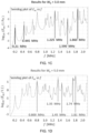
- Fig. 1M shows F rad for symmetric actuation at 1.380 MHz.
- the force vectors are directed towards the side walls of the channel.
- Fig. 1N shows F rad for symmetric actuation at 1.745 MHz.
- the force vectors are directed towards the ceiling of the channel and also towards the side walls of the channel.
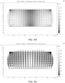
- Fig. 3A shows the acoustic energy E ac for chip 1B
- Fig. 3C shows the acoustic energy E ac for chip 1F
- the microfluidic flow channel was provided on one surface of the substrate to which the lid was bonded so as to seal the channel.
- a planar piezoceramic crystal was provided with a common grounded single bottom electrode attached to its bottom surface.
- First and second top electrode were formed on the top surface by deposition on an electrode material after which the electrode material was divided into the first and second top electrodes by sawing through the electrode material and approximately 400 ⁇ m into the top surface of the piezoceramic crystal.
- the gap between the first and second top electrodes was approximately 100 ⁇ m.
- a solution of 8 um diameter polystyrene beads in water with Tween (detergent) was used.
- the piezoceramic crystal was actuated in an asymmetric manner, i.e. with the part of the piezoceramic crystal defined between the first top electrode and the single bottom electrode being actuated out of phase, by 180°, to the part of the piezoceramic crystal defined between the second top electrode and the single bottom electrode.
- the frequency was manually scanned in 10 kHz steps from 0.6 to 2 MHz.
- the function generator was set to 10 Vpp with a 180° phase difference between the transducers.
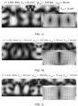
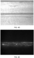
- Fig. 4A shows a microscope bright field image of chip 1A, showing the channel.
- Fig. 4B is a fluorescence image showing beads in channel without ultrasound at 50 ⁇ l/min. As seen from the image there is no focusing of the beads in the channel.
- Fig. 4C shows how beads are focused to the center of the channel when the chip is actuated asymmetrically at a frequency of 1.3 MHz, with an amplitude of 10 V pp , and at a flowrate of 50 ⁇ l/min.
- Fig. 4D shows a microscope bright field image of chip 1B, which is of the same type as chip 1A.
- Fig. 4E is a Fluorescence image showing beads in channel without ultrasound at 50 ⁇ L/min. As seen from the image there is no focusing of the beads in the channel.
- Fig. 4F shows how beads are focused to the center of the channel when the chip is actuated asymmetrically at a frequency of 1.55 MHz, with an amplitude of 10 V pp , and at a flowrate of 100 ⁇ l/min.
- Fig. 4G shows how beads are focused to the center of the channel when the chip is actuated asymmetrically at a frequency of 1.55 MHz, with an amplitude of 10 V pp , and at a flowrate of 200 ⁇ l/min.
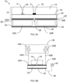
- the general construction of an acoustophoretic chip of an acoustophoretic device according to the second aspect of the present invention is shown schematically and in cross section in fig. 5A .
- the acoustophoretic chip or device 10 thus comprises a polymeric substrate 12 made up of a base substrate 14 into which lower surface 16 (or upper surface depending on the orientation) a microfluidic flow channel 18 is provided, either during a moulding step when the base substrate is moulded, such as by injection moulding, or in a subsequent step of precision machining, such as by milling.
- the microfluidic flow channel 18 thus initially resembles a groove or trough on one of the surfaces of the base substrate 14, a floor, or roof depending on the orientation, to the channel 18 is provided by bonding, such as by solvent bonding (where a solvent partially dissolves the surfaces of two objects to be joined) or using an adhesive, a lid substrate 20 to the lower surface 16 of the base substrate 14. A fluid may then be led through the flow channel 18 so as to introduce and/or pass a liquid or fluid sample through the chip 10.
- Actuation of the polymeric substrate is provided by first and second ultrasound transducers 22A and 22B which are constructed so as to share a single common piezoelectric crystal 24.
- An electrode material is provided on the upper surface 26 of the piezoelectric crystal 24, whereafter a cut is made through this layer of electrode material and also preferably, as shown, partially down into the upper surface 26 of the piezoelectric crystal 24 to form a cut-out or groove 28 in the electrode material and the upper surface 26, thus leading to the formation of first and second 30A, 30B spaced apart electrodes.
- On the bottom surface 32 of the piezoelectric crystal 24 a layer of electrode material is similarly applied, however no cut is needed as this layer is to form a common ground electrode 34 for the first and second electrodes 30A; 30B.
- the thus formed two ultrasound transducers 22A and 22B are then attached to the lid substrate 20 by a bonding layer of for instance adhesive 36.
- a liquid or suspension 2 is provided in the flow channel 18. Acoustic forces then affect particles in the liquid, such as particle 4 in the further microfluidic flow channel 18', and thereby perform an acoustophoretic operation in the liquid and the particles.
- the generally non-homogenous pressure fields arising in the substrate when in resonance can be used by placing a further, or a plurality of further, microfluidic flow channel(s) 18' in the substrate 12. If the forces arising on the particle 4 in the further microfluidic flow channel are the same as would affect the same particle in the microfluidic flow channel 18, then both microfluidic flow channel 19 and 18' may be used to perform the same acoustophoretic operation. If that is not the case different acoustophoretic operations may be performed in the different flow channels.
- the ultrasound transducers 22A, 22B are attached to the lid substrate 20, thus providing a shorter distance between the ultrasound actuators and the microfluidic flow channel 18.
- Fig. 5B shows an acoustophoretic device according to the second aspect of the present invention including, in addition to the substrate with the ultrasound transducers shown in Fig. 5A also the drive circuit.
- a drive circuit 38 includes two function generators 40A and 40B capable of sending out signals at or near a resonance frequency of the substrate 12 including the base substrate 14 and the lid substrate 20 (see fig. 5A ) by first and second signal leads 42A and 42B connected to the first and second electrodes 30A and 30B on the piezoelectric crystal 24.
- the ground electrode 34 is then connected to ground 44 via a ground lead 46.
- drive circuit 38 outputs, using function generators 40A and 40B, signals, which preferably are in antiphase, which are led to the first and second electrodes 30A and 30B, so as to actuate the polymeric substrate 12 asymmetrically at the resonance frequency of the polymeric substrate 12 in order to perform an acoustophoretic operation in the channel 18.
- the resonance frequency is the resonance frequency of the combination of the polymeric substrate 12, preferably including the microfluidic flow channel 18, and the ultrasound transducer 22A, 22B (including the piezoelectric crystal 24 with the electrodes 30, 30B and 34).
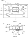
- Figs. 5C and 5D shows a top view and a cross sectional view, respectively, of a microfluidic system 100 according to the fourth aspect of the present invention.
- the microfluidic system 100 includes a main substrate 102, which is made from a polymeric material, and which includes at least one microfluidic channel 104 having an at least one inlet 106 and one or more outlets 108, 110, 112, the channel being formed by milling or moulding grooves or troughs in the surface of the main substrate 102.
- Microfluidic systems typically comprise modules for performing various functions such as mixing, reacting, collecting a fluidic sample, such modules being exemplified by a collection cavity 114 for collecting a fluid sample, and also by holding and/or mixing section 116 in which the channel 104 is convoluted.
- microfluidic systems typically are made from polymeric materials
- the inclusion of an acoustophoretic region or module where acoustophoretic operations are to be carried out would be difficult or complicated if silicon or glass were to be used for these functions, as these materials differ from the material of the main substrate 102 of the microfluidic system 100, thus requiring separate manufacturing followed by assembling the silicon/glass parts with the main substrate.
- the acoustophoretic operations may be performed using a module or chip integrated with the main substrate 102 of the microfluidic system 100.
- a section 118 of the microfluidic channel 104 may thus be arranged to pass through a region 120 of the base substrate 102 in which region 120 an acoustophoretic operation is to be carried out.
- Fig. 5D which is a cross section of Fig. 5C through the line AA', it can be seen that the main substrate 102 comprises a main base substrate 122 joined to is joined with a lid substrate 124, which similar to the device in fig.
- 5A serves to define the floor or ceiling of the channel 118.
- the ultrasound transducers 22A and 22B are attached to the lid substrate 124 opposite the region 120.
- these grooves may even pass right through the main base substrate 122 all the way to the other surface 128 so as to define a chip 130 that is integrated in the base substrate 102 and which only connects to the remainder of the base substrate 102 where the channel 118 enters and exits the region 120.
- the ultrasound transducers 22A and 22B are actuated.
- a sample flowing through the region 120 is exposed to acoustic forces in the channel 118, such as for example forces that focus particles towards the center of the channel 118.
- the channel 118 branches into the first and second side channels 132 and 134, the concentrated and focused particles thus flow, due to the laminar nature of the flow, into the central channel 136 and outlet 110, whereas other parts of the sample are led to outlet 108 and 112.
- Fig. 6A shows the method according to the first aspect of the present invention, including the steps of:
- Fig. 6B shows the method according to the third aspect of present invention, including the steps of:
Landscapes
- Chemical & Material Sciences (AREA)
- Health & Medical Sciences (AREA)
- Clinical Laboratory Science (AREA)
- Analytical Chemistry (AREA)
- General Health & Medical Sciences (AREA)
- Hematology (AREA)
- Dispersion Chemistry (AREA)
- Chemical Kinetics & Catalysis (AREA)
- Physics & Mathematics (AREA)
- Fluid Mechanics (AREA)
- Life Sciences & Earth Sciences (AREA)
- Molecular Biology (AREA)
- Physical Or Chemical Processes And Apparatus (AREA)
Claims (15)
- Verfahren zum Durchführen einer akustophoretischen Operation, umfassend die Schritte:a. Bereitstellen eines akustophoretischen Chips (10), der ein Polymersubstrat (12) umfasst, in dem ein mikrofluidischer Strömungskanal (18) positioniert ist,b. Bereitstellen von mindestens zwei Ultraschallwandlern (22A, 22B) in akustischem Kontakt mit einer Oberfläche des Substrats,c. Ansteuern der mindestens zwei Ultraschallwandler mit einer Frequenz f, die einem akustischen Resonanzpeak des Substrats einschließlich des mit einer Flüssigkeitssuspension (2) gefüllten mikrofluidischen Strömungskanals entspricht, undd. Bereitstellen der Flüssigkeitssuspension in dem Strömungskanal, um die akustophoretische Operation an der Flüssigkeitssuspension durchzuführen.
- Verfahren nach Anspruch 1, wobei der akustische Resonanzpeak der dreidimensionalen Volumenresonanz in dem Substrat einschließlich des mikrofluidischen Strömungskanals entspricht, wobei die dreidimensionale Volumenresonanz nicht als ein- oder zweidimensionale Resonanz in dem Substrat beschrieben werden kann.
- Verfahren nach Anspruch 1 oder 2, wobei die Frequenz f nicht einer Resonanzfrequenz des Kanals allein entspricht.
- Verfahren nach einem der Ansprüche 1-3, wobei in Schritt c die mindestens zwei Ultraschallwandler phasenverschoben, vorzugsweise gegenphasig, zueinander angesteuert werden.
- Verfahren nach Anspruch 4, wobei sich die wenigstens zwei Ultraschallwandler einen gemeinsamen piezoelektrischen Kristall (24) teilen.
- Verfahren nach einem der Ansprüche 1-5, wobei die akustophoretische Operation Fokussieren von Partikeln, suspendiert in einer Suspension innerhalb des mikrofluidischen Strömungskanals, in Richtung eines oder mehrerer diskreter Bereiche des mikrofluidischen Strömungskanals umfasst.
- Vorrichtung zum Durchführen einer akustophoretischen Operation,
umfassend:einen akustophoretischen Chip (10), der ein Polymersubstrat (12) und einen mikrofluidischen Strömungskanal (18), der innerhalb des Substrats positioniert ist, umfasstmindestens zwei Ultraschallwandler (22A, 22B) in akustischem Kontakt mit einer Oberfläche des Substrats undeine Ansteuerschaltung (38), die mit den mindestens zwei Ultraschallwandlern verbunden ist und dazu konfiguriert ist, die mindestens zwei Ultraschallwandler mit einer Frequenz f anzusteuern, die einem akustischen Resonanzpeak des Substrats einschließlich des mit einer flüssigen Suspension gefüllten mikrofluidischen Strömungskanals entspricht. - Akustophoretische Vorrichtung nach Anspruch 7, wobei die Ansteuerschaltung ferner dazu konfiguriert ist, die wenigstens zwei Ultraschallwandler bei der akustischen Resonanzfrequenz f phasenverschoben, vorzugsweise gegenphasig, zueinander anzusteuern.
- Akustophoretische Vorrichtung nach einem der Ansprüche 7-8, wobei das Substrat zusätzlich einen weiteren mikrofluidischen Strömungskanal (18') umfasst, wobei der weitere mikrofluidische Strömungskanal so positioniert ist, dass eine akustische Kraft aufgrund von Resonanz in dem Substrat einschließlich des mikrofluidischen Strömungskanals und des weiteren mikrofluidischen Strömungskanals auf ein Zielpartikel (4) in dem weiteren mikrofluidischen Kanal entsteht, wobei die akustische Kraft gleich oder verschieden von einer akustischen Kraft ist, die auf ein Zielpartikel in dem mikrofluidischen Kanal entsteht.
- Verfahren zum Herstellen eines akustophoretischen Chips (12) zum Durchführen einer akustophoretischen Operation, wobei der akustophoretische Chip ein Polymersubstrat (12) umfasst, in dem ein mikrofluidischer Strömungskanal (18) bereitgestellt ist, umfassend die Schritte:a. Bestimmen der akustischen Resonanzen des Substrats für jede einer Vielzahl von verschiedenen Kombinationen von Parameterwerten von Substratparametern durch Berechnung oder Simulation, wobei die Substratparameter polymeres Substratmaterial, Substratabmessungen, Abmessungen des mikrofluidischen Strömungskanals, Positionen des mikrofluidischen Strömungskanals innerhalb des Substrats, Eigenschaften einer Flüssigkeit in dem mikrofluidischen Strömungskanal, Positionen für mindestens zwei Ultraschallwandler in akustischem Kontakt mit einer Oberfläche des Substrats und Ansteuerfrequenz f umfassen, undb. Auswählen eines polymeren Substratmaterials M, eines Satzes von Substratdimensionen DS, eines Satzes von Abmessungen des mikrofluidischen Strömungskanals DC, einer Position des mikrofluidischen Strömungskanal PC innerhalb des Substrats, Eigenschaften der Flüssigkeit L in dem mikrofluidischen Strömungskanal, einer Position PU für mindestens zwei Ultraschallwandler in akustischem Kontakt mit einer Oberfläche des Substrats und einer Ansteuerfrequenz f unter den mehreren verschiedenen Kombinationen der Parameterwerte der Substratparameter, die akustische Resonanz innerhalb des Substrats einschließlich des mit einer Flüssigkeitssuspension gefüllten mikrofluidischen Strömungskanals zum Durchführen der akustophoretischen Operation ergeben undc. Herstellen des akustophoretischen Chips aus dem Substratmaterial M mit den Substratabmessungen DS und versehen mit einem mikrofluidischen Strömungskanal mit den Abmessungend des mikrofluidischen Strömungskanals DC und der Position des mikrofluidischen Strömungskanals P C innerhalb des Substrats.
- Verfahren nach Anspruch 10, wobei in Schritt a) eine Simulation verwendet wird, wobei die Simulation die Polymer/Luft-Grenzfläche an den Außenflächen des Substrats und die Polymer/Flüssigkeit-Grenzfläche an Wänden des mikrofluidischen Strömungskanals als Grenzen verwendet.
- Verfahren nach einem der Ansprüche 10-11, wobei Schritt a ferner Bestimmen der akustischen Kraft auf ein Zielpartikel (4) im gesamten Substrat für jede der Vielzahl von verschiedenen Kombinationen von Parameterwerten von Substratparametern umfasst, und Schritt b ferner Bestimmen des Satzes von Abmessungen des mikrofluidischen Strömungskanals DC und der Position des mikrofluidischen Strömungskanals PC innerhalb des Substrats umfasst, sodass der mikrofluidische Strömungskanal mindestens teilweise einen Bereich des Substrats begrenzt, in dem die akustische Kraft auf das Zielpartikel zum Durchführen der akustophoretischen Operation geeignet ist.
- Verfahren nach einem der Ansprüche 10-12, wobei der akustophoretische Chip zum Durchführen einer weiteren akustophoretischen Operation geeignet ist, und wobei die Substratparameter zusätzlich weitere Abmessungen des mikrofluidischen Strömungskanals und weitere Positionen des mikrofluidischen Strömungskanals innerhalb des Substrats für einen weiteren mikrofluidischen Strömungskanal (18') umfassen.
- Verfahren nach Anspruch 13, wobei sich die akustophoretische Operation und die weitere akustophoretische Operation unterscheiden, und wobei Schritt b ferner das Bestimmen eines weiteren Satzes von Abmessungen des mikrofluidischen Strömungskanals DC2 und von Positionen des mikrofluidischen Strömungskanals PC2 innerhalb des Substrats umfasst, sodass der weitere mikrofluidische Strömungskanal mindestens teilweise einen weiteren Bereich des Substrats begrenzt, in dem die akustische Kraft auf ein Zielpartikel zum Durchführen der weiteren akustophoretischen Operation geeignet ist.
- Mikrofluidisches System, umfassend die Vorrichtung nach einem der Ansprüche 7-9, umfassendein polymeres Hauptsubstrat (122) mit einer Substratoberfläche, in der ein erster Satz von Vorsprüngen, wie etwa Wänden, oder Vertiefungen, wie etwa Nuten, ausgebildet ist,ein polymeres Deckelsubstrat (124), das über der Substratoberfläche platziert ist, um zusammen mit dem ersten Satz von Vorsprüngen oder Vertiefungen mindestens einen mikrofluidischen Strömungskanal (104) zu definieren,wobei sich ein Teil (118) des mikrofluidischen Strömungskanals durch einen akustophoretischen Bereich (120) des Hauptsubstrats erstreckt, in dem eine akustophoretische Operation durchgeführt werden soll, wobei der akustophoretische Bereich den akustophoretischen Chip definiert,wobei ein zweiter Satz von Vorsprüngen oder Vertiefungen (126A, 126B) in dem polymeren Hauptsubstrat in oder neben dem akustophoretischen Bereich vorgesehen ist, um den akustophoretischen Bereich mindestens teilweise von dem Rest des polymeren Hauptsubstrats zu trennen, undwobei die mindestens zwei Ultraschallwandler (22A, 22B) auf der von der Substratoberfläche abgewandten Seite des polymeren Deckelsubstrats in akustischem Kontakt mit dem polymeren Deckelsubstrat stehen, wobei die mindestens zwei Ultraschallwandler auf dem polymeren Deckelsubstrat so positioniert sind, dass sie mindestens einen Teil des akustophoretischen Bereichs bedecken, undwobei die Ansteuerschaltung (38) mit den mindestens zwei Ultraschallwandlern verbunden und dazu konfiguriert ist, die mindestens zwei Ultraschallwandler bei einer Frequenz f entsprechend einem Resonanzpeak des akustophoretischen Bereichs des polymeren Hauptsubstrats, einschließlich des mit einer flüssigen Suspension gefüllten mikrofluidischen Strömungskanals und eines Teils des polymeren Deckelsubstrats, der dem akustophoretischen Bereich zugewandt ist, vorzugsweise phasenverschoben oder gegenphasig anzusteuern.
Applications Claiming Priority (2)
| Application Number | Priority Date | Filing Date | Title |
|---|---|---|---|
| EP17188920 | 2017-08-31 | ||
| PCT/EP2018/073542 WO2019043198A1 (en) | 2017-08-31 | 2018-08-31 | METHODS AND DEVICES FOR ACOUSTOPHORETICAL OPERATIONS IN POLYMERIC CHIPS |
Publications (2)
| Publication Number | Publication Date |
|---|---|
| EP3676005A1 EP3676005A1 (de) | 2020-07-08 |
| EP3676005B1 true EP3676005B1 (de) | 2024-09-25 |
Family
ID=59923223
Family Applications (1)
| Application Number | Title | Priority Date | Filing Date |
|---|---|---|---|
| EP18769088.8A Active EP3676005B1 (de) | 2017-08-31 | 2018-08-31 | Verfahren und vorrichtungen für akustophoretische operationen in polymerchips |
Country Status (4)
| Country | Link |
|---|---|
| US (1) | US11331668B2 (de) |
| EP (1) | EP3676005B1 (de) |
| JP (1) | JP7232246B2 (de) |
| WO (1) | WO2019043198A1 (de) |
Families Citing this family (7)
| Publication number | Priority date | Publication date | Assignee | Title |
|---|---|---|---|---|
| EP4035776A1 (de) | 2021-01-28 | 2022-08-03 | AcouSort AB | Vorrichtungen und verfahren für akustofluidische operationen unter verwendung von dünnschicht-ultraschallwandlern |
| EP4094833A1 (de) * | 2021-05-25 | 2022-11-30 | AcouSort AB | Akustofluidische verfahren und vorrichtungen mit verwendung von schwebender elektrode |
| EP4101535A1 (de) * | 2021-06-11 | 2022-12-14 | AcouSort AB | Akustofluidische vorrichtung mit konfiguration zur ermöglichung von resonanzfrequenzverfolgung und verfahren dafür |
| JP2023037337A (ja) * | 2021-09-03 | 2023-03-15 | セイコーエプソン株式会社 | 流体デバイス |
| TR2021018663A2 (tr) * | 2021-11-29 | 2023-06-21 | Ihsan Dogramaci Bilkent Ueniversitesi | Çok aşamalı mikro ve biyolojik parçacık manipülasyonu için çok katmanlı entegre akustoforetik mikro akışkan cihaz |
| WO2023244275A1 (en) * | 2022-06-17 | 2023-12-21 | Siemens Healthcare Diagnostics Inc. | Acoustophoresis devices having conductive electrodes and methods |
| TR2022021706A2 (tr) * | 2022-12-30 | 2024-07-22 | Koc Ueniversitesi | Hibrit yapıda bir mikroakışkan çip ve bunun kanser türevi hastalıkların erken tanısında kullanımı. |
Family Cites Families (7)
| Publication number | Priority date | Publication date | Assignee | Title |
|---|---|---|---|---|
| JP4770251B2 (ja) | 2005-04-25 | 2011-09-14 | パナソニック株式会社 | 成分分離デバイスおよびこれを用いた成分の分離方法 |
| WO2007083295A2 (en) | 2006-01-19 | 2007-07-26 | Yeda Research And Development Co. Ltd. | Device and method for particle manipulation in fluid |
| JP4984849B2 (ja) | 2006-11-27 | 2012-07-25 | パナソニック株式会社 | 成分分離デバイスと、この成分分離デバイスを用いた化学分析デバイス |
| ATE538377T1 (de) | 2007-04-02 | 2012-01-15 | Acoustic Cytometry Systems Inc | Verfahren zur verbesserten analyse von in einem akustischen feld fokussierten zellen und partikeln |
| JP5118714B2 (ja) | 2010-03-10 | 2013-01-16 | エムエス・ソリューションズ株式会社 | マイクロ流体デバイス |
| US9695390B2 (en) * | 2010-08-23 | 2017-07-04 | President And Fellows Of Harvard College | Acoustic waves in microfluidics |
| US9821310B2 (en) * | 2011-03-31 | 2017-11-21 | The University Of Akron | Two-stage microfluidic device for acoustic particle manipulation and methods of separation |
-
2018
- 2018-08-31 EP EP18769088.8A patent/EP3676005B1/de active Active
- 2018-08-31 WO PCT/EP2018/073542 patent/WO2019043198A1/en not_active Ceased
- 2018-08-31 JP JP2020512542A patent/JP7232246B2/ja active Active
- 2018-08-31 US US16/641,421 patent/US11331668B2/en active Active
Also Published As
| Publication number | Publication date |
|---|---|
| JP2020532418A (ja) | 2020-11-12 |
| US20200238280A1 (en) | 2020-07-30 |
| JP7232246B2 (ja) | 2023-03-02 |
| WO2019043198A1 (en) | 2019-03-07 |
| EP3676005A1 (de) | 2020-07-08 |
| US11331668B2 (en) | 2022-05-17 |
Similar Documents
| Publication | Publication Date | Title |
|---|---|---|
| EP3676005B1 (de) | Verfahren und vorrichtungen für akustophoretische operationen in polymerchips | |
| US8865003B2 (en) | Apparatus and method for separation of particles suspended in a liquid from the liquid in which they are suspended | |
| Ma et al. | Mechanical properties based particle separation via traveling surface acoustic wave | |
| EP2903715B1 (de) | Technologie für akustophoretische trennung mit mehrdimensionalen stehenden wellen | |
| US20170080423A1 (en) | Device for the Separation of Particles Using a Bulk Acoustic Wave Field | |
| Lickert et al. | Acoustophoresis in polymer-based microfluidic devices: Modeling and experimental validation | |
| US20050106064A1 (en) | Microfluidic cell and method for sample handling | |
| CN107921332A (zh) | 用于倾斜波颗粒偏转的声泳装置 | |
| US10807029B2 (en) | High throughput acoustic particle separation methods and devices | |
| Shields IV et al. | Fabrication and operation of acoustofluidic devices supporting bulk acoustic standing waves for sheathless focusing of particles | |
| Zaheri-Ghannad et al. | Acoustic-assisted centrifugal microfluidics for particle/cell separation | |
| Jonai et al. | Two-dimensional acoustic focusing of microparticles in a rectangular microchannel using a dual-frequency-excited single transducer | |
| CN220425377U (zh) | 一种基于声子晶体结构进行粒子分选的微流控装置 | |
| CN116393183B (zh) | 一种基于声子晶体结构进行粒子分选的微流控装置 | |
| Ahmad et al. | Evaluation of acoustic-based particle separation methods | |
| EP4534172A1 (de) | Zweidimensionale akustische partikelfokussierungsvorrichtung und akustische konzentrationsvorrichtung damit | |
| Luzuriaga et al. | Acoustophoretic particle manipulation in hybrid solid/gel resonators | |
| US20260049911A1 (en) | Particle two-dimensional acoustic focusing device, and acoustic concentration device using the same | |
| WO2023096612A1 (en) | Multilayer integrated acoustophoretic microfluidic device for multi-stage micro and biological particle manipulation | |
| Yigit et al. | Acoustofluidic microdevice for precise control of pressure nodal positions | |
| Zaheri-Ghannad et al. | Cell/particle manipulation using Bulk Acoustic Waves (BAWs) on centrifugal microfluidic platforms: A mathematical study | |
| Taheri et al. | Analysis of Newtonian and non-Newtonian impacts on acoustic separation of CTCs | |
| CN120861179A (zh) | 一种基于声流控的亚波长颗粒分离装置 | |
| Vuille-dit-Bille et al. | On-chip particle levitation and micromanipulation using bulk acoustic waves | |
| Jonai et al. | Two-dimensional acoustic focusing of microparticles in a rectangular microchannel using a dual |
Legal Events
| Date | Code | Title | Description |
|---|---|---|---|
| STAA | Information on the status of an ep patent application or granted ep patent |
Free format text: STATUS: UNKNOWN |
|
| STAA | Information on the status of an ep patent application or granted ep patent |
Free format text: STATUS: THE INTERNATIONAL PUBLICATION HAS BEEN MADE |
|
| PUAI | Public reference made under article 153(3) epc to a published international application that has entered the european phase |
Free format text: ORIGINAL CODE: 0009012 |
|
| STAA | Information on the status of an ep patent application or granted ep patent |
Free format text: STATUS: REQUEST FOR EXAMINATION WAS MADE |
|
| 17P | Request for examination filed |
Effective date: 20200124 |
|
| AK | Designated contracting states |
Kind code of ref document: A1 Designated state(s): AL AT BE BG CH CY CZ DE DK EE ES FI FR GB GR HR HU IE IS IT LI LT LU LV MC MK MT NL NO PL PT RO RS SE SI SK SM TR |
|
| AX | Request for extension of the european patent |
Extension state: BA ME |
|
| DAV | Request for validation of the european patent (deleted) | ||
| DAX | Request for extension of the european patent (deleted) | ||
| STAA | Information on the status of an ep patent application or granted ep patent |
Free format text: STATUS: EXAMINATION IS IN PROGRESS |
|
| 17Q | First examination report despatched |
Effective date: 20230706 |
|
| GRAP | Despatch of communication of intention to grant a patent |
Free format text: ORIGINAL CODE: EPIDOSNIGR1 |
|
| STAA | Information on the status of an ep patent application or granted ep patent |
Free format text: STATUS: GRANT OF PATENT IS INTENDED |
|
| INTG | Intention to grant announced |
Effective date: 20231025 |
|
| GRAJ | Information related to disapproval of communication of intention to grant by the applicant or resumption of examination proceedings by the epo deleted |
Free format text: ORIGINAL CODE: EPIDOSDIGR1 |
|
| STAA | Information on the status of an ep patent application or granted ep patent |
Free format text: STATUS: EXAMINATION IS IN PROGRESS |
|
| INTC | Intention to grant announced (deleted) | ||
| GRAP | Despatch of communication of intention to grant a patent |
Free format text: ORIGINAL CODE: EPIDOSNIGR1 |
|
| STAA | Information on the status of an ep patent application or granted ep patent |
Free format text: STATUS: GRANT OF PATENT IS INTENDED |
|
| INTG | Intention to grant announced |
Effective date: 20240424 |
|
| GRAS | Grant fee paid |
Free format text: ORIGINAL CODE: EPIDOSNIGR3 |
|
| GRAA | (expected) grant |
Free format text: ORIGINAL CODE: 0009210 |
|
| STAA | Information on the status of an ep patent application or granted ep patent |
Free format text: STATUS: THE PATENT HAS BEEN GRANTED |
|
| AK | Designated contracting states |
Kind code of ref document: B1 Designated state(s): AL AT BE BG CH CY CZ DE DK EE ES FI FR GB GR HR HU IE IS IT LI LT LU LV MC MK MT NL NO PL PT RO RS SE SI SK SM TR |
|
| REG | Reference to a national code |
Ref country code: GB Ref legal event code: FG4D |
|
| REG | Reference to a national code |
Ref country code: CH Ref legal event code: EP |
|
| REG | Reference to a national code |
Ref country code: DE Ref legal event code: R096 Ref document number: 602018074727 Country of ref document: DE |
|
| REG | Reference to a national code |
Ref country code: IE Ref legal event code: FG4D |
|
| P01 | Opt-out of the competence of the unified patent court (upc) registered |
Free format text: CASE NUMBER: APP_56718/2024 Effective date: 20241017 |
|
| REG | Reference to a national code |
Ref country code: LT Ref legal event code: MG9D |
|
| PG25 | Lapsed in a contracting state [announced via postgrant information from national office to epo] |
Ref country code: NO Free format text: LAPSE BECAUSE OF FAILURE TO SUBMIT A TRANSLATION OF THE DESCRIPTION OR TO PAY THE FEE WITHIN THE PRESCRIBED TIME-LIMIT Effective date: 20241225 |
|
| PG25 | Lapsed in a contracting state [announced via postgrant information from national office to epo] |
Ref country code: GR Free format text: LAPSE BECAUSE OF FAILURE TO SUBMIT A TRANSLATION OF THE DESCRIPTION OR TO PAY THE FEE WITHIN THE PRESCRIBED TIME-LIMIT Effective date: 20241226 Ref country code: FI Free format text: LAPSE BECAUSE OF FAILURE TO SUBMIT A TRANSLATION OF THE DESCRIPTION OR TO PAY THE FEE WITHIN THE PRESCRIBED TIME-LIMIT Effective date: 20240925 |
|
| PG25 | Lapsed in a contracting state [announced via postgrant information from national office to epo] |
Ref country code: BG Free format text: LAPSE BECAUSE OF FAILURE TO SUBMIT A TRANSLATION OF THE DESCRIPTION OR TO PAY THE FEE WITHIN THE PRESCRIBED TIME-LIMIT Effective date: 20240925 |
|
| PG25 | Lapsed in a contracting state [announced via postgrant information from national office to epo] |
Ref country code: LV Free format text: LAPSE BECAUSE OF FAILURE TO SUBMIT A TRANSLATION OF THE DESCRIPTION OR TO PAY THE FEE WITHIN THE PRESCRIBED TIME-LIMIT Effective date: 20240925 |
|
| PG25 | Lapsed in a contracting state [announced via postgrant information from national office to epo] |
Ref country code: RS Free format text: LAPSE BECAUSE OF FAILURE TO SUBMIT A TRANSLATION OF THE DESCRIPTION OR TO PAY THE FEE WITHIN THE PRESCRIBED TIME-LIMIT Effective date: 20241225 |
|
| REG | Reference to a national code |
Ref country code: NL Ref legal event code: MP Effective date: 20240925 |
|
| PG25 | Lapsed in a contracting state [announced via postgrant information from national office to epo] |
Ref country code: RS Free format text: LAPSE BECAUSE OF FAILURE TO SUBMIT A TRANSLATION OF THE DESCRIPTION OR TO PAY THE FEE WITHIN THE PRESCRIBED TIME-LIMIT Effective date: 20241225 Ref country code: NO Free format text: LAPSE BECAUSE OF FAILURE TO SUBMIT A TRANSLATION OF THE DESCRIPTION OR TO PAY THE FEE WITHIN THE PRESCRIBED TIME-LIMIT Effective date: 20241225 Ref country code: LV Free format text: LAPSE BECAUSE OF FAILURE TO SUBMIT A TRANSLATION OF THE DESCRIPTION OR TO PAY THE FEE WITHIN THE PRESCRIBED TIME-LIMIT Effective date: 20240925 Ref country code: GR Free format text: LAPSE BECAUSE OF FAILURE TO SUBMIT A TRANSLATION OF THE DESCRIPTION OR TO PAY THE FEE WITHIN THE PRESCRIBED TIME-LIMIT Effective date: 20241226 Ref country code: FI Free format text: LAPSE BECAUSE OF FAILURE TO SUBMIT A TRANSLATION OF THE DESCRIPTION OR TO PAY THE FEE WITHIN THE PRESCRIBED TIME-LIMIT Effective date: 20240925 Ref country code: BG Free format text: LAPSE BECAUSE OF FAILURE TO SUBMIT A TRANSLATION OF THE DESCRIPTION OR TO PAY THE FEE WITHIN THE PRESCRIBED TIME-LIMIT Effective date: 20240925 |
|
| REG | Reference to a national code |
Ref country code: AT Ref legal event code: MK05 Ref document number: 1726228 Country of ref document: AT Kind code of ref document: T Effective date: 20240925 |
|
| PG25 | Lapsed in a contracting state [announced via postgrant information from national office to epo] |
Ref country code: NL Free format text: LAPSE BECAUSE OF FAILURE TO SUBMIT A TRANSLATION OF THE DESCRIPTION OR TO PAY THE FEE WITHIN THE PRESCRIBED TIME-LIMIT Effective date: 20240925 |
|
| PG25 | Lapsed in a contracting state [announced via postgrant information from national office to epo] |
Ref country code: PT Free format text: LAPSE BECAUSE OF FAILURE TO SUBMIT A TRANSLATION OF THE DESCRIPTION OR TO PAY THE FEE WITHIN THE PRESCRIBED TIME-LIMIT Effective date: 20250127 Ref country code: IS Free format text: LAPSE BECAUSE OF FAILURE TO SUBMIT A TRANSLATION OF THE DESCRIPTION OR TO PAY THE FEE WITHIN THE PRESCRIBED TIME-LIMIT Effective date: 20250125 |
|
| PG25 | Lapsed in a contracting state [announced via postgrant information from national office to epo] |
Ref country code: RO Free format text: LAPSE BECAUSE OF FAILURE TO SUBMIT A TRANSLATION OF THE DESCRIPTION OR TO PAY THE FEE WITHIN THE PRESCRIBED TIME-LIMIT Effective date: 20240925 Ref country code: SM Free format text: LAPSE BECAUSE OF FAILURE TO SUBMIT A TRANSLATION OF THE DESCRIPTION OR TO PAY THE FEE WITHIN THE PRESCRIBED TIME-LIMIT Effective date: 20240925 |
|
| PG25 | Lapsed in a contracting state [announced via postgrant information from national office to epo] |
Ref country code: ES Free format text: LAPSE BECAUSE OF FAILURE TO SUBMIT A TRANSLATION OF THE DESCRIPTION OR TO PAY THE FEE WITHIN THE PRESCRIBED TIME-LIMIT Effective date: 20240925 |
|
| PG25 | Lapsed in a contracting state [announced via postgrant information from national office to epo] |
Ref country code: EE Free format text: LAPSE BECAUSE OF FAILURE TO SUBMIT A TRANSLATION OF THE DESCRIPTION OR TO PAY THE FEE WITHIN THE PRESCRIBED TIME-LIMIT Effective date: 20240925 Ref country code: AT Free format text: LAPSE BECAUSE OF FAILURE TO SUBMIT A TRANSLATION OF THE DESCRIPTION OR TO PAY THE FEE WITHIN THE PRESCRIBED TIME-LIMIT Effective date: 20240925 |
|
| PG25 | Lapsed in a contracting state [announced via postgrant information from national office to epo] |
Ref country code: CZ Free format text: LAPSE BECAUSE OF FAILURE TO SUBMIT A TRANSLATION OF THE DESCRIPTION OR TO PAY THE FEE WITHIN THE PRESCRIBED TIME-LIMIT Effective date: 20240925 Ref country code: PL Free format text: LAPSE BECAUSE OF FAILURE TO SUBMIT A TRANSLATION OF THE DESCRIPTION OR TO PAY THE FEE WITHIN THE PRESCRIBED TIME-LIMIT Effective date: 20240925 |
|
| PG25 | Lapsed in a contracting state [announced via postgrant information from national office to epo] |
Ref country code: SK Free format text: LAPSE BECAUSE OF FAILURE TO SUBMIT A TRANSLATION OF THE DESCRIPTION OR TO PAY THE FEE WITHIN THE PRESCRIBED TIME-LIMIT Effective date: 20240925 Ref country code: IT Free format text: LAPSE BECAUSE OF FAILURE TO SUBMIT A TRANSLATION OF THE DESCRIPTION OR TO PAY THE FEE WITHIN THE PRESCRIBED TIME-LIMIT Effective date: 20240925 |
|
| REG | Reference to a national code |
Ref country code: DE Ref legal event code: R097 Ref document number: 602018074727 Country of ref document: DE |
|
| PG25 | Lapsed in a contracting state [announced via postgrant information from national office to epo] |
Ref country code: DK Free format text: LAPSE BECAUSE OF FAILURE TO SUBMIT A TRANSLATION OF THE DESCRIPTION OR TO PAY THE FEE WITHIN THE PRESCRIBED TIME-LIMIT Effective date: 20240925 |
|
| PLBE | No opposition filed within time limit |
Free format text: ORIGINAL CODE: 0009261 |
|
| STAA | Information on the status of an ep patent application or granted ep patent |
Free format text: STATUS: NO OPPOSITION FILED WITHIN TIME LIMIT |
|
| 26N | No opposition filed |
Effective date: 20250626 |
|
| PG25 | Lapsed in a contracting state [announced via postgrant information from national office to epo] |
Ref country code: SE Free format text: LAPSE BECAUSE OF FAILURE TO SUBMIT A TRANSLATION OF THE DESCRIPTION OR TO PAY THE FEE WITHIN THE PRESCRIBED TIME-LIMIT Effective date: 20240925 |
|
| PGFP | Annual fee paid to national office [announced via postgrant information from national office to epo] |
Ref country code: DE Payment date: 20250819 Year of fee payment: 8 |
|
| PGFP | Annual fee paid to national office [announced via postgrant information from national office to epo] |
Ref country code: GB Payment date: 20250819 Year of fee payment: 8 |
|
| PGFP | Annual fee paid to national office [announced via postgrant information from national office to epo] |
Ref country code: FR Payment date: 20250818 Year of fee payment: 8 |
|
| PG25 | Lapsed in a contracting state [announced via postgrant information from national office to epo] |
Ref country code: HR Free format text: LAPSE BECAUSE OF FAILURE TO SUBMIT A TRANSLATION OF THE DESCRIPTION OR TO PAY THE FEE WITHIN THE PRESCRIBED TIME-LIMIT Effective date: 20240925 |