EP3675786B1 - Adult incontinent device - Google Patents
Adult incontinent device Download PDFInfo
- Publication number
- EP3675786B1 EP3675786B1 EP18773311.8A EP18773311A EP3675786B1 EP 3675786 B1 EP3675786 B1 EP 3675786B1 EP 18773311 A EP18773311 A EP 18773311A EP 3675786 B1 EP3675786 B1 EP 3675786B1
- Authority
- EP
- European Patent Office
- Prior art keywords
- stretch
- wing
- zone
- nonwoven
- stretch zone
- Prior art date
- Legal status (The legal status is an assumption and is not a legal conclusion. Google has not performed a legal analysis and makes no representation as to the accuracy of the status listed.)
- Active
Links
Images


Classifications
-
- A—HUMAN NECESSITIES
- A61—MEDICAL OR VETERINARY SCIENCE; HYGIENE
- A61F—FILTERS IMPLANTABLE INTO BLOOD VESSELS; PROSTHESES; DEVICES PROVIDING PATENCY TO, OR PREVENTING COLLAPSING OF, TUBULAR STRUCTURES OF THE BODY, e.g. STENTS; ORTHOPAEDIC, NURSING OR CONTRACEPTIVE DEVICES; FOMENTATION; TREATMENT OR PROTECTION OF EYES OR EARS; BANDAGES, DRESSINGS OR ABSORBENT PADS; FIRST-AID KITS
- A61F13/00—Bandages or dressings; Absorbent pads
- A61F13/15—Absorbent pads, e.g. sanitary towels, swabs or tampons for external or internal application to the body; Supporting or fastening means therefor; Tampon applicators
- A61F13/56—Supporting or fastening means
- A61F13/5605—Supporting or fastening means specially adapted for sanitary napkins or the like
- A61F13/5616—Supporting or fastening means specially adapted for sanitary napkins or the like using flaps, e.g. adhesive, for attachment to the undergarment
-
- A—HUMAN NECESSITIES
- A61—MEDICAL OR VETERINARY SCIENCE; HYGIENE
- A61F—FILTERS IMPLANTABLE INTO BLOOD VESSELS; PROSTHESES; DEVICES PROVIDING PATENCY TO, OR PREVENTING COLLAPSING OF, TUBULAR STRUCTURES OF THE BODY, e.g. STENTS; ORTHOPAEDIC, NURSING OR CONTRACEPTIVE DEVICES; FOMENTATION; TREATMENT OR PROTECTION OF EYES OR EARS; BANDAGES, DRESSINGS OR ABSORBENT PADS; FIRST-AID KITS
- A61F13/00—Bandages or dressings; Absorbent pads
- A61F13/15—Absorbent pads, e.g. sanitary towels, swabs or tampons for external or internal application to the body; Supporting or fastening means therefor; Tampon applicators
- A61F13/45—Absorbent pads, e.g. sanitary towels, swabs or tampons for external or internal application to the body; Supporting or fastening means therefor; Tampon applicators characterised by the shape
- A61F13/49—Absorbent pads, e.g. sanitary towels, swabs or tampons for external or internal application to the body; Supporting or fastening means therefor; Tampon applicators characterised by the shape specially adapted to be worn around the waist, e.g. diapers, nappies
- A61F13/49007—Form-fitting, self-adjusting disposable diapers
- A61F13/49009—Form-fitting, self-adjusting disposable diapers with elastic means
- A61F13/49014—Form-fitting, self-adjusting disposable diapers with elastic means the elastic means is located at the side panels
- A61F13/49015—Form-fitting, self-adjusting disposable diapers with elastic means the elastic means is located at the side panels the elastic means being elastic panels
-
- A—HUMAN NECESSITIES
- A61—MEDICAL OR VETERINARY SCIENCE; HYGIENE
- A61F—FILTERS IMPLANTABLE INTO BLOOD VESSELS; PROSTHESES; DEVICES PROVIDING PATENCY TO, OR PREVENTING COLLAPSING OF, TUBULAR STRUCTURES OF THE BODY, e.g. STENTS; ORTHOPAEDIC, NURSING OR CONTRACEPTIVE DEVICES; FOMENTATION; TREATMENT OR PROTECTION OF EYES OR EARS; BANDAGES, DRESSINGS OR ABSORBENT PADS; FIRST-AID KITS
- A61F13/00—Bandages or dressings; Absorbent pads
- A61F13/15—Absorbent pads, e.g. sanitary towels, swabs or tampons for external or internal application to the body; Supporting or fastening means therefor; Tampon applicators
- A61F13/15577—Apparatus or processes for manufacturing
- A61F13/15756—Applying tabs, strips, tapes, loops; Knotting the ends of pads
-
- A—HUMAN NECESSITIES
- A61—MEDICAL OR VETERINARY SCIENCE; HYGIENE
- A61F—FILTERS IMPLANTABLE INTO BLOOD VESSELS; PROSTHESES; DEVICES PROVIDING PATENCY TO, OR PREVENTING COLLAPSING OF, TUBULAR STRUCTURES OF THE BODY, e.g. STENTS; ORTHOPAEDIC, NURSING OR CONTRACEPTIVE DEVICES; FOMENTATION; TREATMENT OR PROTECTION OF EYES OR EARS; BANDAGES, DRESSINGS OR ABSORBENT PADS; FIRST-AID KITS
- A61F13/00—Bandages or dressings; Absorbent pads
- A61F13/15—Absorbent pads, e.g. sanitary towels, swabs or tampons for external or internal application to the body; Supporting or fastening means therefor; Tampon applicators
- A61F13/45—Absorbent pads, e.g. sanitary towels, swabs or tampons for external or internal application to the body; Supporting or fastening means therefor; Tampon applicators characterised by the shape
- A61F13/47—Sanitary towels, incontinence pads or napkins
- A61F13/474—Sanitary towels, incontinence pads or napkins adjustable
-
- A—HUMAN NECESSITIES
- A61—MEDICAL OR VETERINARY SCIENCE; HYGIENE
- A61F—FILTERS IMPLANTABLE INTO BLOOD VESSELS; PROSTHESES; DEVICES PROVIDING PATENCY TO, OR PREVENTING COLLAPSING OF, TUBULAR STRUCTURES OF THE BODY, e.g. STENTS; ORTHOPAEDIC, NURSING OR CONTRACEPTIVE DEVICES; FOMENTATION; TREATMENT OR PROTECTION OF EYES OR EARS; BANDAGES, DRESSINGS OR ABSORBENT PADS; FIRST-AID KITS
- A61F13/00—Bandages or dressings; Absorbent pads
- A61F13/15—Absorbent pads, e.g. sanitary towels, swabs or tampons for external or internal application to the body; Supporting or fastening means therefor; Tampon applicators
- A61F13/45—Absorbent pads, e.g. sanitary towels, swabs or tampons for external or internal application to the body; Supporting or fastening means therefor; Tampon applicators characterised by the shape
- A61F13/49—Absorbent pads, e.g. sanitary towels, swabs or tampons for external or internal application to the body; Supporting or fastening means therefor; Tampon applicators characterised by the shape specially adapted to be worn around the waist, e.g. diapers, nappies
- A61F13/49007—Form-fitting, self-adjusting disposable diapers
- A61F13/49009—Form-fitting, self-adjusting disposable diapers with elastic means
- A61F13/4902—Form-fitting, self-adjusting disposable diapers with elastic means characterised by the elastic material
-
- A—HUMAN NECESSITIES
- A61—MEDICAL OR VETERINARY SCIENCE; HYGIENE
- A61F—FILTERS IMPLANTABLE INTO BLOOD VESSELS; PROSTHESES; DEVICES PROVIDING PATENCY TO, OR PREVENTING COLLAPSING OF, TUBULAR STRUCTURES OF THE BODY, e.g. STENTS; ORTHOPAEDIC, NURSING OR CONTRACEPTIVE DEVICES; FOMENTATION; TREATMENT OR PROTECTION OF EYES OR EARS; BANDAGES, DRESSINGS OR ABSORBENT PADS; FIRST-AID KITS
- A61F13/00—Bandages or dressings; Absorbent pads
- A61F13/15—Absorbent pads, e.g. sanitary towels, swabs or tampons for external or internal application to the body; Supporting or fastening means therefor; Tampon applicators
- A61F13/45—Absorbent pads, e.g. sanitary towels, swabs or tampons for external or internal application to the body; Supporting or fastening means therefor; Tampon applicators characterised by the shape
- A61F13/49—Absorbent pads, e.g. sanitary towels, swabs or tampons for external or internal application to the body; Supporting or fastening means therefor; Tampon applicators characterised by the shape specially adapted to be worn around the waist, e.g. diapers, nappies
- A61F13/493—Absorbent pads, e.g. sanitary towels, swabs or tampons for external or internal application to the body; Supporting or fastening means therefor; Tampon applicators characterised by the shape specially adapted to be worn around the waist, e.g. diapers, nappies adjustable by adding or removing material, e.g. umbilical cord arrangements
-
- A—HUMAN NECESSITIES
- A61—MEDICAL OR VETERINARY SCIENCE; HYGIENE
- A61F—FILTERS IMPLANTABLE INTO BLOOD VESSELS; PROSTHESES; DEVICES PROVIDING PATENCY TO, OR PREVENTING COLLAPSING OF, TUBULAR STRUCTURES OF THE BODY, e.g. STENTS; ORTHOPAEDIC, NURSING OR CONTRACEPTIVE DEVICES; FOMENTATION; TREATMENT OR PROTECTION OF EYES OR EARS; BANDAGES, DRESSINGS OR ABSORBENT PADS; FIRST-AID KITS
- A61F13/00—Bandages or dressings; Absorbent pads
- A61F13/15—Absorbent pads, e.g. sanitary towels, swabs or tampons for external or internal application to the body; Supporting or fastening means therefor; Tampon applicators
- A61F13/45—Absorbent pads, e.g. sanitary towels, swabs or tampons for external or internal application to the body; Supporting or fastening means therefor; Tampon applicators characterised by the shape
- A61F13/49—Absorbent pads, e.g. sanitary towels, swabs or tampons for external or internal application to the body; Supporting or fastening means therefor; Tampon applicators characterised by the shape specially adapted to be worn around the waist, e.g. diapers, nappies
- A61F13/496—Absorbent pads, e.g. sanitary towels, swabs or tampons for external or internal application to the body; Supporting or fastening means therefor; Tampon applicators characterised by the shape specially adapted to be worn around the waist, e.g. diapers, nappies in the form of pants or briefs
-
- A—HUMAN NECESSITIES
- A61—MEDICAL OR VETERINARY SCIENCE; HYGIENE
- A61F—FILTERS IMPLANTABLE INTO BLOOD VESSELS; PROSTHESES; DEVICES PROVIDING PATENCY TO, OR PREVENTING COLLAPSING OF, TUBULAR STRUCTURES OF THE BODY, e.g. STENTS; ORTHOPAEDIC, NURSING OR CONTRACEPTIVE DEVICES; FOMENTATION; TREATMENT OR PROTECTION OF EYES OR EARS; BANDAGES, DRESSINGS OR ABSORBENT PADS; FIRST-AID KITS
- A61F13/00—Bandages or dressings; Absorbent pads
- A61F13/15—Absorbent pads, e.g. sanitary towels, swabs or tampons for external or internal application to the body; Supporting or fastening means therefor; Tampon applicators
- A61F13/56—Supporting or fastening means
- A61F13/5622—Supporting or fastening means specially adapted for diapers or the like
- A61F13/565—Supporting or fastening means specially adapted for diapers or the like pants type diaper
- A61F13/5655—Supporting or fastening means specially adapted for diapers or the like pants type diaper adjustable pants type diapers
-
- B—PERFORMING OPERATIONS; TRANSPORTING
- B32—LAYERED PRODUCTS
- B32B—LAYERED PRODUCTS, i.e. PRODUCTS BUILT-UP OF STRATA OF FLAT OR NON-FLAT, e.g. CELLULAR OR HONEYCOMB, FORM
- B32B5/00—Layered products characterised by the non- homogeneity or physical structure, i.e. comprising a fibrous, filamentary, particulate or foam layer; Layered products characterised by having a layer differing constitutionally or physically in different parts
- B32B5/02—Layered products characterised by the non- homogeneity or physical structure, i.e. comprising a fibrous, filamentary, particulate or foam layer; Layered products characterised by having a layer differing constitutionally or physically in different parts characterised by structural features of a fibrous or filamentary layer
- B32B5/022—Non-woven fabric
-
- B—PERFORMING OPERATIONS; TRANSPORTING
- B32—LAYERED PRODUCTS
- B32B—LAYERED PRODUCTS, i.e. PRODUCTS BUILT-UP OF STRATA OF FLAT OR NON-FLAT, e.g. CELLULAR OR HONEYCOMB, FORM
- B32B5/00—Layered products characterised by the non- homogeneity or physical structure, i.e. comprising a fibrous, filamentary, particulate or foam layer; Layered products characterised by having a layer differing constitutionally or physically in different parts
- B32B5/22—Layered products characterised by the non- homogeneity or physical structure, i.e. comprising a fibrous, filamentary, particulate or foam layer; Layered products characterised by having a layer differing constitutionally or physically in different parts characterised by the presence of two or more layers which are next to each other and are fibrous, filamentary, formed of particles or foamed
- B32B5/24—Layered products characterised by the non- homogeneity or physical structure, i.e. comprising a fibrous, filamentary, particulate or foam layer; Layered products characterised by having a layer differing constitutionally or physically in different parts characterised by the presence of two or more layers which are next to each other and are fibrous, filamentary, formed of particles or foamed one layer being a fibrous or filamentary layer
- B32B5/26—Layered products characterised by the non- homogeneity or physical structure, i.e. comprising a fibrous, filamentary, particulate or foam layer; Layered products characterised by having a layer differing constitutionally or physically in different parts characterised by the presence of two or more layers which are next to each other and are fibrous, filamentary, formed of particles or foamed one layer being a fibrous or filamentary layer another layer next to it also being fibrous or filamentary
-
- A—HUMAN NECESSITIES
- A61—MEDICAL OR VETERINARY SCIENCE; HYGIENE
- A61F—FILTERS IMPLANTABLE INTO BLOOD VESSELS; PROSTHESES; DEVICES PROVIDING PATENCY TO, OR PREVENTING COLLAPSING OF, TUBULAR STRUCTURES OF THE BODY, e.g. STENTS; ORTHOPAEDIC, NURSING OR CONTRACEPTIVE DEVICES; FOMENTATION; TREATMENT OR PROTECTION OF EYES OR EARS; BANDAGES, DRESSINGS OR ABSORBENT PADS; FIRST-AID KITS
- A61F13/00—Bandages or dressings; Absorbent pads
- A61F13/15—Absorbent pads, e.g. sanitary towels, swabs or tampons for external or internal application to the body; Supporting or fastening means therefor; Tampon applicators
- A61F2013/15008—Absorbent pads, e.g. sanitary towels, swabs or tampons for external or internal application to the body; Supporting or fastening means therefor; Tampon applicators characterized by the use
- A61F2013/15121—Absorbent pads, e.g. sanitary towels, swabs or tampons for external or internal application to the body; Supporting or fastening means therefor; Tampon applicators characterized by the use for mild incontinence
-
- A—HUMAN NECESSITIES
- A61—MEDICAL OR VETERINARY SCIENCE; HYGIENE
- A61F—FILTERS IMPLANTABLE INTO BLOOD VESSELS; PROSTHESES; DEVICES PROVIDING PATENCY TO, OR PREVENTING COLLAPSING OF, TUBULAR STRUCTURES OF THE BODY, e.g. STENTS; ORTHOPAEDIC, NURSING OR CONTRACEPTIVE DEVICES; FOMENTATION; TREATMENT OR PROTECTION OF EYES OR EARS; BANDAGES, DRESSINGS OR ABSORBENT PADS; FIRST-AID KITS
- A61F13/00—Bandages or dressings; Absorbent pads
- A61F13/15—Absorbent pads, e.g. sanitary towels, swabs or tampons for external or internal application to the body; Supporting or fastening means therefor; Tampon applicators
- A61F2013/15008—Absorbent pads, e.g. sanitary towels, swabs or tampons for external or internal application to the body; Supporting or fastening means therefor; Tampon applicators characterized by the use
- A61F2013/1513—Absorbent pads, e.g. sanitary towels, swabs or tampons for external or internal application to the body; Supporting or fastening means therefor; Tampon applicators characterized by the use for anal discharge
-
- A—HUMAN NECESSITIES
- A61—MEDICAL OR VETERINARY SCIENCE; HYGIENE
- A61F—FILTERS IMPLANTABLE INTO BLOOD VESSELS; PROSTHESES; DEVICES PROVIDING PATENCY TO, OR PREVENTING COLLAPSING OF, TUBULAR STRUCTURES OF THE BODY, e.g. STENTS; ORTHOPAEDIC, NURSING OR CONTRACEPTIVE DEVICES; FOMENTATION; TREATMENT OR PROTECTION OF EYES OR EARS; BANDAGES, DRESSINGS OR ABSORBENT PADS; FIRST-AID KITS
- A61F13/00—Bandages or dressings; Absorbent pads
- A61F13/15—Absorbent pads, e.g. sanitary towels, swabs or tampons for external or internal application to the body; Supporting or fastening means therefor; Tampon applicators
- A61F2013/15008—Absorbent pads, e.g. sanitary towels, swabs or tampons for external or internal application to the body; Supporting or fastening means therefor; Tampon applicators characterized by the use
- A61F2013/15146—Absorbent pads, e.g. sanitary towels, swabs or tampons for external or internal application to the body; Supporting or fastening means therefor; Tampon applicators characterized by the use for urine collection
Definitions
- the invention is generally directed to adult incontinent devices, particularly the 'wings' used in those devices.
- the incontinent device market may be divided into two segments, baby devices (or diapers) and adult devices (or briefs).
- the baby and adult segments are different because of many factors including, but not limited to: wearer considerations (babies versus adults), purchasers (parents versus wearer), and needs (toilet training for babies versus medical needs for adults). Accordingly, the innovation drivers for these two segments are different and cannot be conflated.
- the current products need improvement.
- the components used to fasten the device around the adult wearer typically a wing
- the wings used on adult incontinent devices are made from two or more subcomponents that must be joined together before attachment to the device.
- Such multi-component wings at least, increase the complexity (and cost) of manufacture, and render a less attractive device.
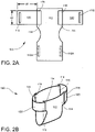
- FIGs 1A and 1B such a prior art device is illustrated.
- device 10 has a chassis 12 including an attachment surface 14, and a wing 20 attached, via a bond 16, to the chassis 12.
- the wing 20 is made from several subcomponents, e.g., first non-stretch zone 22 overlapping and joined to stretch zone 26 overlapping and joined to second non-stretch zone 24.
- the device 10 may include a fastener (or fastener component) 18 at the distal end of wing 20.
- the overlapping components are illustrated in cross-section based on a partial cross-section of the figure 1A . At the overlaps (or seams) 28, 30, the subcomponents are joined together.
- overlaps at least, increase the complexity of manufacture, increase waste by underutilizing a portion of the subcomponent, decrease the attractiveness of the device, decrease the comfort of the device, and increase the risk of skin irritations by friction.
- the device with such overlaps introduces winding and unwinding difficulties due to different thickness of the product packaged on a roll.
- multi-components wings introduce insecurity for the user. For example, the joint between the two adjacent components may unintentionally break during the use of the device, thereby putting the user in a difficult/uncomfortable/embarrassing position.
- the invention provides a method for making an adult incontinent device as defined comprising the steps of:
- a wing for an adult incontinent device as defined in claim 7 is disclosed.
- the adult incontinent device has a chassis with a lateral attachment surface.
- the wing includes a stretch laminate with at least one nonwoven layer and at least one elastic layer.
- the nonwoven layer and the elastic layer are bound together in face-to-face contact.
- the stretch laminate has at least one stretch zone and at least one non-stretch zone, a width of the elastic layer in the stretch zone is equal to or in a range of 25-90% of a width of the non-stretch zone.
- the stretch laminate has no overlap portions between the stretch zone and the non-stretch zone.
- One end of the wing is affixed to the lateral attachment surface of the chassis.
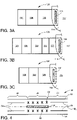
- the device 100 generally includes a chassis 112 (conventional) with wings 120 affixed thereto, in particular two wings.
- the device is closable, meaning that on the free (or distal) end of wing 120 is added a fastener component (e.g., hook & loop fastener and/or adhesive) 118 (and a mate 118A, if necessary, on another part of the chassis) that allows multiple openings and closing of the device, and the fixed (or proximal) end is affixed (in any conventional manner - e.g., bonded 116 with adhesive, thermal weld, ultrasound weld, stitching) to the attachment surface 114 of the chassis 112.
- a fastener component e.g., hook & loop fastener and/or adhesive
- the device 100 is closed, meaning that both ends of the wing 120 are fixedly attached (in any conventional manner - e.g., bonded 116 with adhesive, thermal weld, ultrasound weld, stitching) to the attachment surfaces 114 of the chassis 112.
- any conventional manner - e.g., bonded 116 with adhesive, thermal weld, ultrasound weld, stitching
- the invention will be discussed with reference to the embodiment shown in Figure 2A , but the invention is equally applicable to either embodiment.
- Wing 120 generally includes at least one stretch zone 126 and one non-stretch zone 122 and/or 124.
- the stretch zone 126 and non-stretch zones 122, 124 may alternate with one another.
- the wing 120 has no overlaps (or seams), as discussed above, and may be made using a continuous layer (from one lateral side to an opposite lateral side) of nonwoven, i.e., no overlap or seam.
- the wing 120 is an integral (or unitary or seamless) component with no seams joining the subcomponent, i.e., the stretch zone 126 and the non-stretch zones 122, 124.
- Wing 120 may be a stretch laminate or a stretch laminate with at least one stretch zone and at least one non-stretch zone.
- a stretch zone may be elastic in at least the cross-machine direction (CD).
- the non-stretch zone may be non-elastic (or non-stretchable) in at least the cross-machine direction.
- Each wing has at least one elastic layer.
- the wing may have two, or at least two, elastic layers.
- the wing may have three, or at least three, elastic layers.
- the wing may have four, or at least four, elastic layers.
- a stretch laminate may comprise four elastic layers from which two wings may be formed. When a prior art wing is compared to the inventive wing, for the same extension, the width of the inventive wing may be less than the width of the prior art wing.
- the stretch laminate may be any stretch laminate.
- Stretch laminate generally refers to a material comprising a nonwoven layer and an elastic layer bonded together in face-to-face contact. The bonding may be autogenous and/or facilitated by adhesives and/or welding (e.g., thermal, ultrasonic, or both).
- the area of the elastic layer (or film) may be less than the area of the nonwoven layer, whereby elastic lanes (or zones) are created between inelastic lanes (or zones).
- the elastic lanes may be activated, non-activated, partially activated (activated over only a portion of the elastic lane) and/or activated to varying degrees. Activation may be accomplished by stretching (e.g., ring rolling).
- the stretch laminate includes a top nonwoven, a bottom nonwoven with an elastic film sandwiched therebetween. Thereinafter for convenience, the stretch laminate 120 will be described as the latter.
- Stretch laminate 50 shown exploded, generally includes a top nonwoven 52, a bottom nonwoven 54, and an elastic film 56 sandwiched therebetween.
- the portion 58 of the stretch laminate with the elastic film defines the stretch zone (or elastic lane), and the portion 60 of the stretch laminate without the elastic film defines the non-stretch zone (or inelastic lane).
- the nonwovens 52, 54 are bonded to the elastic film via a bond pattern 62, so that the elasticity of the film is not impeded (or only partially impeded) by the nonwovens.
- the nonwovens 52, 54 are bonded together via a bond pattern 64 and/or by use of a stiffening material (e.g., non-elastic film or foil), so that any possible stretchability of the bonded nonwovens is reduced or eliminated.
- the non-stretch zone may comprise two nonwoven layers that is fixed between them by fixing means selected from the group consisting of an adhesive layer, an ultrasonic bonding, thermo-calendering, cold calendering or a combination thereof.
- the non-stretch zone may comprise an additional material as reinforcing material between the two nonwoven layers.
- the non-stretch zone may not have to require an additional material for integrity or reinforcement as the two fixed nonwoven layers will be of adequate strength, corresponding to the non-stretch zone.
- stretch laminates in general, reference is made to US Patent No. 7794819 , to which one can refer when reading the present application.
- the bond pattern 64 may be any bond pattern.
- the bond pattern 64 may be made with adhesives and/or welding (heat and/or ultrasonic).
- the stretch zone, the elastic layer, and the non-stretch zone each have a width.
- the width of the elastic layer equal to the width of the non-stretch zone, or the width of the elastic layer is within the range of 25-90% of the non-stretch zone, and/or the width of the elastic layer may be within the range of 40-80% of the width of the non-stretch zone.
- Nonwoven refers to any nonwoven.
- the nonwoven may be: a carded nonwoven, an air laid nonwoven, a wet laid nonwoven, a melt-blown (M) nonwoven, a spunbonded (S) nonwoven, a spunlaced nonwoven, a combined M and S nonwoven (for example, SM, SMS, SMMS, SSMMS), and/or combinations thereof.
- the nonwoven is a spunbond nonwoven.
- the fibers (staple and/or filament) may be made of any material, for example, polyester (e.g., PET), polyamide (e.g., nylon), polyolefin (e.g., PE, PP), copolymers thereof, or a blend thereof.
- the nonwoven may have a basis weight in the range of 10-40 g/m 2 , and in another embodiment, in the range of 22-30 g/m 2 .
- the top and bottom nonwovens may be the same or different.
- the nonwoven may have apertures or be in a precut form.
- Elastic refers to any elastic material.
- the elastic films may be made from any elastomeric polymer mainly a thermoplastic elastomer.
- the elastomeric polymers may be styrenic block copolymers.
- Styrenic block copolymers include, but are not limited to, SIS (styrene-isoprene-styrene) block copolymers, SBS (styrene-butene-styrene) block copolymers, or SEBS (Styrene-Ethylene-Butene-Styrene) or oleophilic elastomer based as for example Vistamaxx TM polymer available by ExxonMobil Chemical and combinations thereof.
- the elastic film may have any basis weight, in one embodiment, of 20-100 g/m 2 , and in another 40-100 g/m 2 , or in another 30-90 g/m 2 or in another 40-70 g/m 2 .
- the elastic film could be a unique elastic film structure or a multilayer elastic film structure comprising an elastic film structure and at least one layer of skin layer structure or at least an elastic film structure in sandwich between two skin layer structures.
- Wing 120 has one stretch zone 126 between two non-stretch zones, 122, 124.
- the one (or proximal) end, e.g., a non-stretch zone, of the wing 120 is affixed to the attachment surface 114 of the chassis 112 via bond 116.
- the other (or distal) end of the wing may include a fastener component 118 or be affixed to another part of the chassis 112.
- the widths and lengths of the stretch zones and non-stretch zones may vary.
- a second embodiment of the wing 120 is shown.
- the wing may have multiple stretch zones 126 and multiple non-stretch zones 122, 124.
- the stretch zones alternate with the non-stretch zones.
- multiple stretch zones and multiple non-stretch zones maybe grouped together.
- the one (or proximal) end, e.g., a non-stretch zone, of the wing 120 is affixed to the attachment surface 114 of the chassis 112 via bond 116.
- the other (or distal) end of the wing may include a fastener component 118 or be affixed to another part of the chassis 112.
- the widths and lengths of the stretch zones and non-stretch zones may vary.
- a third embodiment of wing 120 is shown.
- the wing has a different order of stretch zones 126 and non-stretch zones 124.
- the one (or proximal) end, e.g., a stretch zone, of the wing 120 is affixed to the attachment surface 114 of the chassis 112 via bond 116.
- the other (or distal) end of the wing may include a fastener component 118 or be affixed to another part of the chassis 112.
- the widths and lengths of the stretch zones and non-stretch zones may vary.
- One layer of non-woven extending continuously and approximately in a unique plane from an area of the layer of non-woven layer intended to be join to one attachment surface 114 of the chassis 112 to an opposite area of the layer of non-woven layer intended to be join to an opposite attachment surface 114 of the chassis 112.
- This unique plane may be approximately flattened when the wing is laid on a flattened support. This unique plane could be curved if the wing is joined to the chassis.
- One layer of nonwoven of the wing may have a continuous path from an area near to one attachment surfaces 114 of the chassis 112 to an opposite area.
- the opposite area may either near to another attachment surface 114 of the chassis 112 or near to the free end of the wing, in particular near to the fastener component 118.
- the continuous path is defined as without passing through an interface as another layer of nonwoven or a join of two wings of multi-component wings as defined in the background.
- Each of the two nonwoven layers of the wing according to the invention may have a continuous path between an area near to one attachment surface 114 of the chassis 112 and an opposite area near to an opposite attachment surface 114 of the chassis 112.
- the wing 120 may have a dimension d1, see Figure 2A (i.e., in the cross-machine direction or CD).
- the dimension d1 may be greater than 100mm, 110mm, 120mm, 130mm, 140mm, 150mm, 160mm or 170mm. In wing 120, d1 may be less than 400mm.
- the dimension d1 may be less than 600mm.
- the dimension d1 is measured, in Figure 2A - from the chassis to the free end of the wing or in Figure 2B - between the two opposite edges of the chassis, in particular in a direction sensibly perpendicular to a direction defined by the chassis or in a direction sensibly perpendicular to the edge of the wing bond to the chassis.
- Wing 120 may have a dimension d2, see Figure 2A (i.e., in the machine direction or MD) between 100 mm and 300 mm, in some embodiment between 125 mm and 250 mm. Wing 120, when used in the adult device, may have a circumference of between 400mm and 3000mm, or between 550mm and 2500mm. In some embodiment, the circumference may be 559mm (22 inch) for a small size and may be, at least, 2438mm (96 inches) for bariatric size (alternatively, 2591 mm (102 inches) for bariatric size, or 2693mm (106 inches) for bariatric size).
- the wing may have one surface area higher than 10 000 mm 2 , 11 000 mm 2 , 12 000 mm 2 , 13 000 mm 2 , 14 000 mm 2 , 15 000 mm 2 , 16 000 mm 2 , 17 000 mm 2 , 20 000 mm 2 , 25 000 mm 2 , 30 000 mm 2 , 35 000 mm 2 , 40 000 mm 2 .
- the wing may have one surface area between 11 000 mm 2 and 200 000 mm 2 , in particular between 11 000 mm 2 and 150 000 mm 2 , in particular between 15 000 mm 2 and 120 000mm 2 , in particular between 50 000 mm 2 and 85 000 mm 2 .
- the wing may have one surface area between 50,000 mm2 and 150,000mm2. The dimension of the wing is measured when the wing is at a relaxed stage, just before using it, for example just after removing it from the bag.
- the 'capacity of utilization' of the one elastic layer of the wing may be defined by the following ratio: B"/B', see Figure 1B .
- 'capacity of utilization' indicates the portion of the elastic layer that is used for stretching and represents waste (or underutilization of the elastic layer - the elastic layer is relatively more expensive that the nonwoven layer and un-utilized elastic increases the cost of the device without increased benefit).
- the 'capacity of utilization' of the one elastic layer of the wing is around 60% (or 40% of the elastic layer of the wing is not utilized (or un-utilized) for elasticity).
- the 'capacity of utilization' of the one elastic layer of the wing according to the invention is approximately 100%.
- the wing 120 has a reduced cost when compared to prior art wings.
- the present invention may be directed to the adult devices and may have no applicability to baby devices (or not directed to the baby devices). However, some aspects of the invention may have applicability to baby devices.
- one stretch zone may have a middle line ML extending in the middle of the stretch zone in parallel of the two opposite outside faces of the stretch zone, in MD direction and/or in CD direction.
- the middle line ML of the stretch zone extending in the thickness of the stretch zone.
- One non-stretch zone may have one middle line ML extending in the middle of the non-stretch zone in parallel of the two opposite outside faces of the non-stretch zone, in MD direction or in CD direction.
- the middle line ML of the non-stretch zone extending in the thickness of the non-stretch zone.
- a middle line ML of one stretch zone and a middle line of one adjacent non-stretch zone may be the same.
- one middle line of the stretch zone and a middle line of one adjacent non-stretch zone may define a gap G.
- the gap is less than 50% of the thickness of the stretch zone and/or the gap G is less than 50% of the thickness of the non-stretch zone.
- the gap may be less than one of the following rate 45%, 40%, 35%, 30%, 25%, 20% or 15% of the thickness of one stretch zone and/or one non-stretch zone.
- the gap may be between 0 mm and 15 mm, in particular between 0 mm and 10 mm, in particular between 0 mm and 5 mm, in particular between 0 mm and 2 mm, in particular between 0 mm and 1 mm.
- the thicknesses of the stretch zone and the non-stretch zone may be measured with the method described in ASTM D3774-96(2004).
- a stretch zone is a zone having an elastic set less than a non-stretch zone.
- a stretch zone may be a zone having elastic set less than 40%, in particular less than 20%.
- the elastic set may be measured according to the method described in ASTM D2731-15.
- the stretch zone and/or the non-stretch zone may be aperture in full width or partially.
- aperture in general, reference is made to US Patent application No. 15/489,812 , to which one can refer when reading the present application.
- One elastic layer may have a middle line extending in the middle of the elastic layer in parallel of the two opposite outside faces of the elastic layer, in MD direction and/or in CD direction.
- One nonwoven layer may have a middle line extending in the middle of the nonwoven layer in parallel of the two opposite outside faces of the nonwoven layer, in MD direction or in CD direction.
- the middle line of a nonwoven layer extends in the thickness of the nonwoven layer.
- a middle line of one elastic layer and a middle line of one adjacent nonwoven layer may be the same.
- one middle line of the elastic layer and one middle line of one adjacent nonwoven layer may define a gap.
- the gap is less than 50% of the thickness of the elastic layer and/or the gap is less than 50% of the thickness of the nonwoven layer. In some embodiments, the gap may be less than one of the following rate 45%, 40%, 35%, 30%, 25%, 20% or 15% of the thickness of one elastic layer and/or one nonwoven layer.
- the gap may be between 0 mm and 15 mm, in particular between 0 mm and 10 mm, in particular between 0 mm and 5 mm, in particular between 0 mm and 2 mm, in particular between 0 mm and 1 mm.
- the gap (“gap") according to the Fig 1B (Prior art) is at least 400% of the thickness (e1, e2) respectively of the stretch zone and the non-stretch zone.
- the thicknesses of the elastic layer and the nonwoven layer may be measured according to the method described in ASTM D3774-96(2004).
- An elastic layer is a layer having an elastic set less than a nonwoven layer.
- An elastic layer may be a zone having elastic set less than 40%, in particular less than 20%.
- the elastic set may be measured according to the method described in ASTM D2731-15.
- the elastic layer and/or the nonwoven layer may be apertured in full width or partially.
- Apertured means that the wing (or stretch laminate) is provided with a plurality of holes or small holes, so that that the wing (or stretch laminate) may breathe when in contact with the wearer (or in contact with the wearer's skin).
- the apertures may be any aperture that is sufficient to provide breathability (or comfort) to the wearer.
- the aperture may have an area of 0.2-0.6 mm 2 . In another the area may be of 0.30-0.50 mm 2 . In another, the area may be of 0.02-0.20 mm 2 . In yet another embodiment, the area may be about 0.04 mm 2 .
- the apertures may be formed by pins (or heated pins).
- the number of apertures may be in the range of 2-6 apertures/cm 2 .
- the number of apertures may be in a range of 3-5 apertures/ cm 2 .
- the apertures may be in about 4/cm 2 .
- the wing (or stretch laminate) may be fully or partially apertured.
- the wing (or stretch laminate) may have at least 45% or 50% or 60% or 70%, or 80%, or 90%, or 95% of the surface area of the wing (or stretch laminate) apertured.
- the stretch laminate may comprise at least one pattern of adhesive layer.
- One stretch zone may have a pattern of adhesive layer and one non-stretch zone may have a pattern of adhesive layer, the pattern of adhesive layer of the stretch zone and the pattern of adhesive layer of the non-stretch zone may be similar, in particular are in full shape or in stripe shape extending in machine direction and spaced in cross direction.
- the stretch laminate may comprise a unique pattern of adhesive layer.
- One stretch zone may have a pattern of adhesive layer and one non-stretch zone may have a pattern of adhesive layer, the pattern of adhesive layer of the stretch zone may be different of the pattern of adhesive layer of the non-stretch zone, in particular in full shape in the non-stretch zone and in stripe shape extending in machine direction and spaced in cross direction in the stretch zone.
- the fastener components 118 and 118A may be a hook and loop fastener.
- the hook and loop fastener may be any hook and loop fastener.
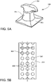
- FIGS 5A and 5B one embodiment of a hook 300 is illustrated and is further disclosed in WO2017187096 ; WO2017187097 ; and WO2017187098 , to which one can refer when reading the present application.
- Figure 5A shows that hook 300 has a base 302, a stem 304, and a cap 306. Cap 306 has a greater diameter than stem 304.
- a plurality of hooks 300 may be disposed (or formed with or formed integrally with) a ribbon 310.
- Fastener component 118 (which may be hooks or mushroom) may be affixed along a lateral edge portion or the roll good.
- fastener components 118 (which may be hooks or mushroom) may be affixed along a center portion of the roll, or along the lateral edge portions of the roll good.
- the fastener may be manufacture by using a molding apparatus, comprising a molding belt.
- the molding belt may be mounted on rotating drive means (for example, comprising at least two rollers), the molding belt comprising an inner face and an outer face, the inner face being mounted against the rotating drive means, the molding belt comprising a plurality of cavities, each cavity defining a stem extending from the outer face towards the inner face, and comprising an end forming a head extending from the stem towards the inner face of the molding belt.
- a molding material may be distributed on the outer side of the molding belt by a material distribution means arranged opposite the molding belt so as to define an air gap between the material distribution means and the molding belt, the step of dispensing the molding material being carried out so as to fill said air gap and the molding material cavities to form a tape comprising a base the thickness of which is defined by the air gap, and the stem and the head, the stem and the head being formed by the plastic material in the cavities of the molding belt, the stem and the head being demolded in order to obtain directly or indirectly the fastener.
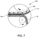
- FIG. 7 illustrates an embodiment of the method 400 for affixing a thermoplastic ribbon 310 of hooks 300 to a nonwoven (e.g., 52 and/or 54) via an autogenous bond 330. While bond 330 is illustrated as pressing the softened thermoplastic of the ribbon into the nonwoven (e.g., without the use of adhesive), the bond may be formed with an adhesive and/or by welding (e.g., thermal and/or ultrasonic).
- wings 120 may be supplied in roll form (or roll goods).
- the wings 120 may be disposed across the width of the roll and down the length of the roll. Any number of wings 120 may be disposed across the width of the roll and down the length of the roll.
- Figure 6A illustrates a cross-section of an embodiment of a roll with four stretch zones 58 and five non-stretch zones 60.
- Figure 6B illustrates a cross-section of an embodiment of a roll with a single wing 120 with two stretch zones 58 and three non-stretch zones 60.
- Figure 6C illustrates a cross-section of an embodiment of a roll with two wings 120 (note the dashed dividing line) disposed across the width of the roll.
- the dimension d1 is 288 mm
- d2 is 240 mm
- the width of the elastic lanes are equal and that width is 45 mm
- the wing have a surface area of 69,120 mm 2
- the middle line of the stretch zone and the middle line of the non-stretch zone are the same, thus the gap is 0 mm.
- the dimension d1 is 288 mm
- d2 is 240 mm
- the width of the elastic lanes are equal and that width is 45 mm
- the wing have a surface area of 69,120 mm 2
- the middle line of the stretch zone and the middle line of the non-stretch zone are the same, thus the gap is 0 mm.
Landscapes
- Health & Medical Sciences (AREA)
- Engineering & Computer Science (AREA)
- Epidemiology (AREA)
- Life Sciences & Earth Sciences (AREA)
- Heart & Thoracic Surgery (AREA)
- Vascular Medicine (AREA)
- Biomedical Technology (AREA)
- Animal Behavior & Ethology (AREA)
- General Health & Medical Sciences (AREA)
- Public Health (AREA)
- Veterinary Medicine (AREA)
- Textile Engineering (AREA)
- Manufacturing & Machinery (AREA)
- Absorbent Articles And Supports Therefor (AREA)
- Orthopedics, Nursing, And Contraception (AREA)
Description
- The invention is generally directed to adult incontinent devices, particularly the 'wings' used in those devices.
- The incontinent device market may be divided into two segments, baby devices (or diapers) and adult devices (or briefs). The baby and adult segments are different because of many factors including, but not limited to: wearer considerations (babies versus adults), purchasers (parents versus wearer), and needs (toilet training for babies versus medical needs for adults). Accordingly, the innovation drivers for these two segments are different and cannot be conflated.
- In the adult incontinent device market, the current products need improvement. For example, the components used to fasten the device around the adult wearer, typically a wing, are wanting from a manufacturing point of view and a utility point of view. Currently, the wings used on adult incontinent devices are made from two or more subcomponents that must be joined together before attachment to the device. Such multi-component wings, at least, increase the complexity (and cost) of manufacture, and render a less attractive device.
- In
Figures 1A and 1B , such a prior art device is illustrated. InFigure 1A ,device 10 has achassis 12 including anattachment surface 14, and awing 20 attached, via abond 16, to thechassis 12. Thewing 20 is made from several subcomponents, e.g.,first non-stretch zone 22 overlapping and joined tostretch zone 26 overlapping and joined tosecond non-stretch zone 24. Thedevice 10 may include a fastener (or fastener component) 18 at the distal end ofwing 20. InFigure 1B , the overlapping components are illustrated in cross-section based on a partial cross-section of thefigure 1A . At the overlaps (or seams) 28, 30, the subcomponents are joined together. These overlaps (or seams), at least, increase the complexity of manufacture, increase waste by underutilizing a portion of the subcomponent, decrease the attractiveness of the device, decrease the comfort of the device, and increase the risk of skin irritations by friction. In addition, the device with such overlaps introduces winding and unwinding difficulties due to different thickness of the product packaged on a roll. Additionally, such multi-components wings introduce insecurity for the user. For example, the joint between the two adjacent components may unintentionally break during the use of the device, thereby putting the user in a difficult/uncomfortable/embarrassing position. - Accordingly, there is a need for new wings for use in adult incontinent devices (or briefs).
- For the purpose of illustrating the invention, there is shown in the drawings a form that is presently preferred; it being understood, however, that this invention is not limited to the precise arrangements and instrumentalities shown.
-
Figures 1A and 1B illustrate a conventional (prior art) wing used in adult incontinent devices, theFigure 1B is a cross sectional view of the wing of thefigure 1A according to thecut 1B-1B. -
Figures 2A and 2B illustrate embodiments of adult incontinent devices utilizing embodiments of the instant invention. -
Figures 3A, 3B, and 3C illustrate various embodiments of the instant invention. -
Figure 4 illustrates an embodiment of a stretch laminate used in the instant invention. -
Figures 5A and 5B illustrate an embodiment of a hook and a ribbon carrying a plurality of hooks. -
Figures 6A ,6B, and 6C illustrate embodiments of the invention. -
Figure 7 illustrates an embodiment of a method for joining a fastener component with the invention. - The invention provides a method for making an adult incontinent device as defined comprising the steps of:
- providing a chassis for the adult incontinent device, the chassis having a lateral attachment surface;
- affixing a wing to the lateral attachment surface, the wing is a stretch laminate with at least one nonwoven layer and at least one elastic layer, the nonwoven layer and the elastic layer are bound together in face-to-face contact, the stretch laminate has at least one stretch zone with the elastic layer and at least one non-stretch zone without the elastic layer, a width of the elastic layer in the stretch zone is equal to or in a range of 25-90% of a width of the non-stretch zone, the stretch laminate has no overlap portions between the stretch zone and the non-stretch zone; and
- thereby forming the adult incontinent device.
- A wing for an adult incontinent device as defined in claim 7 is disclosed. The adult incontinent device has a chassis with a lateral attachment surface. The wing includes a stretch laminate with at least one nonwoven layer and at least one elastic layer. The nonwoven layer and the elastic layer are bound together in face-to-face contact. The stretch laminate has at least one stretch zone and at least one non-stretch zone, a width of the elastic layer in the stretch zone is equal to or in a range of 25-90% of a width of the non-stretch zone. The stretch laminate has no overlap portions between the stretch zone and the non-stretch zone. One end of the wing is affixed to the lateral attachment surface of the chassis.
- Referring to
Figures 2A, 2B ,3A, 3B ,3C ,6A ,6B, and 6C , several exemplary embodiments of the instant invention are illustrated. Like numerals are used for like elements. - Referring to
Figures 2A and 2B , two embodiments of theadult incontinent device 100 are illustrated. Thedevice 100 generally includes a chassis 112 (conventional) withwings 120 affixed thereto, in particular two wings. InFigure 2A , the device is closable, meaning that on the free (or distal) end ofwing 120 is added a fastener component (e.g., hook & loop fastener and/or adhesive) 118 (and amate 118A, if necessary, on another part of the chassis) that allows multiple openings and closing of the device, and the fixed (or proximal) end is affixed (in any conventional manner - e.g., bonded 116 with adhesive, thermal weld, ultrasound weld, stitching) to theattachment surface 114 of thechassis 112. InFigure 2B , thedevice 100 is closed, meaning that both ends of thewing 120 are fixedly attached (in any conventional manner - e.g., bonded 116 with adhesive, thermal weld, ultrasound weld, stitching) to theattachment surfaces 114 of thechassis 112. Thereinafter for convenience, the invention will be discussed with reference to the embodiment shown inFigure 2A , but the invention is equally applicable to either embodiment. - Referring to
Figures 3A, 3B, and 3C , several embodiments ofwing 120 are illustrated. Wing 120 generally includes at least onestretch zone 126 and onenon-stretch zone 122 and/or 124. Thestretch zone 126 andnon-stretch zones wing 120 has no overlaps (or seams), as discussed above, and may be made using a continuous layer (from one lateral side to an opposite lateral side) of nonwoven, i.e., no overlap or seam. Thewing 120 is an integral (or unitary or seamless) component with no seams joining the subcomponent, i.e., thestretch zone 126 and thenon-stretch zones - The stretch laminate may be any stretch laminate. Stretch laminate generally refers to a material comprising a nonwoven layer and an elastic layer bonded together in face-to-face contact. The bonding may be autogenous and/or facilitated by adhesives and/or welding (e.g., thermal, ultrasonic, or both). In the stretch laminate, the area of the elastic layer (or film) may be less than the area of the nonwoven layer, whereby elastic lanes (or zones) are created between inelastic lanes (or zones). The elastic lanes may be activated, non-activated, partially activated (activated over only a portion of the elastic lane) and/or activated to varying degrees. Activation may be accomplished by stretching (e.g., ring rolling). In some embodiments, the stretch laminate includes a top nonwoven, a bottom nonwoven with an elastic film sandwiched therebetween. Thereinafter for convenience, the
stretch laminate 120 will be described as the latter. - One embodiment of a portion of a
stretch laminate 50 is illustrated inFigure 4 .Stretch laminate 50, shown exploded, generally includes a top nonwoven 52, abottom nonwoven 54, and anelastic film 56 sandwiched therebetween. Theportion 58 of the stretch laminate with the elastic film defines the stretch zone (or elastic lane), and theportion 60 of the stretch laminate without the elastic film defines the non-stretch zone (or inelastic lane). In thestretch zone 58, thenonwovens bond pattern 62, so that the elasticity of the film is not impeded (or only partially impeded) by the nonwovens. In the non-stretch zone, 60, thenonwovens bond pattern 64 and/or by use of a stiffening material (e.g., non-elastic film or foil), so that any possible stretchability of the bonded nonwovens is reduced or eliminated. The non-stretch zone may comprise two nonwoven layers that is fixed between them by fixing means selected from the group consisting of an adhesive layer, an ultrasonic bonding, thermo-calendering, cold calendering or a combination thereof. The non-stretch zone may comprise an additional material as reinforcing material between the two nonwoven layers. The non-stretch zone may not have to require an additional material for integrity or reinforcement as the two fixed nonwoven layers will be of adequate strength, corresponding to the non-stretch zone. Regarding stretch laminates, in general, reference is made toUS Patent No. 7794819 , to which one can refer when reading the present application. Thebond pattern 64 may be any bond pattern. Thebond pattern 64 may be made with adhesives and/or welding (heat and/or ultrasonic). - The stretch zone, the elastic layer, and the non-stretch zone each have a width. In the stretch zone, the width of the elastic layer equal to the width of the non-stretch zone, or the width of the elastic layer is within the range of 25-90% of the non-stretch zone, and/or the width of the elastic layer may be within the range of 40-80% of the width of the non-stretch zone. For example, if the inventive wing is 300mm wide and has 2 elastic films, each with a 45mm width, then the elastic film is 43% (90/(300-90)x100=43% [stretch:non-stretch ratio]; if the inventive wing is 225mm wide and has 2 elastic films, each with a 45mm width, then the elastic film is 67% (90/(225-90)x100=67% [stretch:non-stretch ratio]; , if the inventive wing is 215mm wide and has 2 elastic films, each with a 45mm width, then the elastic film is 72% (90/(215-90)x100=72% [stretch:non-stretch ratio]; if the inventive wing is 205mm wide and has 2 elastic films, each with a 45mm width, then the elastic film is 78% (90/(205-90)x100=78% [stretch:non-stretch ratio]
- Nonwoven refers to any nonwoven. The nonwoven may be: a carded nonwoven, an air laid nonwoven, a wet laid nonwoven, a melt-blown (M) nonwoven, a spunbonded (S) nonwoven, a spunlaced nonwoven, a combined M and S nonwoven (for example, SM, SMS, SMMS, SSMMS), and/or combinations thereof. In one embodiment, the nonwoven is a spunbond nonwoven. The fibers (staple and/or filament) may be made of any material, for example, polyester (e.g., PET), polyamide (e.g., nylon), polyolefin (e.g., PE, PP), copolymers thereof, or a blend thereof. In one embodiment, the nonwoven may have a basis weight in the range of 10-40 g/m2, and in another embodiment, in the range of 22-30 g/m2. The top and bottom nonwovens may be the same or different. The nonwoven may have apertures or be in a precut form.
- Elastic refers to any elastic material. The elastic films may be made from any elastomeric polymer mainly a thermoplastic elastomer. In one embodiment, the elastomeric polymers may be styrenic block copolymers. Styrenic block copolymers include, but are not limited to, SIS (styrene-isoprene-styrene) block copolymers, SBS (styrene-butene-styrene) block copolymers, or SEBS (Styrene-Ethylene-Butene-Styrene) or oleophilic elastomer based as for example Vistamaxx™ polymer available by ExxonMobil Chemical and combinations thereof. The elastic film may have any basis weight, in one embodiment, of 20-100 g/m2, and in another 40-100 g/m2, or in another 30-90 g/m2 or in another 40-70 g/m2. The elastic film could be a unique elastic film structure or a multilayer elastic film structure comprising an elastic film structure and at least one layer of skin layer structure or at least an elastic film structure in sandwich between two skin layer structures.
- In
Figure 3A , a first embodiment of thewing 120 is shown.Wing 120 has onestretch zone 126 between two non-stretch zones, 122, 124. The one (or proximal) end, e.g., a non-stretch zone, of thewing 120 is affixed to theattachment surface 114 of thechassis 112 viabond 116. The other (or distal) end of the wing may include afastener component 118 or be affixed to another part of thechassis 112. The widths and lengths of the stretch zones and non-stretch zones may vary. - In
Figure 3B , a second embodiment of thewing 120 is shown. In this embodiment, the wing may havemultiple stretch zones 126 and multiplenon-stretch zones wing 120 is affixed to theattachment surface 114 of thechassis 112 viabond 116. The other (or distal) end of the wing may include afastener component 118 or be affixed to another part of thechassis 112. The widths and lengths of the stretch zones and non-stretch zones may vary. - In
Figure 3C , a third embodiment ofwing 120 is shown. In this embodiment, the wing has a different order ofstretch zones 126 andnon-stretch zones 124. The one (or proximal) end, e.g., a stretch zone, of thewing 120 is affixed to theattachment surface 114 of thechassis 112 viabond 116. The other (or distal) end of the wing may include afastener component 118 or be affixed to another part of thechassis 112. The widths and lengths of the stretch zones and non-stretch zones may vary. - One layer of non-woven extending continuously and approximately in a unique plane from an area of the layer of non-woven layer intended to be join to one
attachment surface 114 of thechassis 112 to an opposite area of the layer of non-woven layer intended to be join to anopposite attachment surface 114 of thechassis 112. This unique plane may be approximately flattened when the wing is laid on a flattened support. This unique plane could be curved if the wing is joined to the chassis. - One layer of nonwoven of the wing may have a continuous path from an area near to one attachment surfaces 114 of the
chassis 112 to an opposite area. The opposite area may either near to anotherattachment surface 114 of thechassis 112 or near to the free end of the wing, in particular near to thefastener component 118. In other word, the continuous path is defined as without passing through an interface as another layer of nonwoven or a join of two wings of multi-component wings as defined in the background. - Each of the two nonwoven layers of the wing according to the invention may have a continuous path between an area near to one
attachment surface 114 of thechassis 112 and an opposite area near to anopposite attachment surface 114 of thechassis 112. - The
wing 120 may have a dimension d1, seeFigure 2A (i.e., in the cross-machine direction or CD). The dimension d1 may be greater than 100mm, 110mm, 120mm, 130mm, 140mm, 150mm, 160mm or 170mm. Inwing 120, d1 may be less than 400mm. The dimension d1 may be less than 600mm. The dimension d1 is measured, inFigure 2A - from the chassis to the free end of the wing or inFigure 2B - between the two opposite edges of the chassis, in particular in a direction sensibly perpendicular to a direction defined by the chassis or in a direction sensibly perpendicular to the edge of the wing bond to the chassis. The ears for the baby device have a length in CD from the chassis to the end hook tab of less than 100mm.Wing 120 may have a dimension d2, seeFigure 2A (i.e., in the machine direction or MD) between 100 mm and 300 mm, in some embodiment between 125 mm and 250 mm.Wing 120, when used in the adult device, may have a circumference of between 400mm and 3000mm, or between 550mm and 2500mm. In some embodiment, the circumference may be 559mm (22 inch) for a small size and may be, at least, 2438mm (96 inches) for bariatric size (alternatively, 2591 mm (102 inches) for bariatric size, or 2693mm (106 inches) for bariatric size). The wing may have one surface area higher than 10 000 mm2, 11 000 mm2, 12 000 mm2, 13 000 mm2, 14 000 mm2, 15 000 mm2, 16 000 mm2, 17 000 mm2, 20 000 mm2, 25 000 mm2, 30 000 mm2, 35 000 mm2, 40 000 mm2. The wing may have one surface area between 11 000 mm2 and 200 000 mm2, in particular between 11 000 mm2 and 150 000 mm2, in particular between 15 000 mm2 and 120 000mm2, in particular between 50 000 mm2 and 85 000 mm2. The wing may have one surface area between 50,000 mm2 and 150,000mm2. The dimension of the wing is measured when the wing is at a relaxed stage, just before using it, for example just after removing it from the bag. - The 'capacity of utilization' of the one elastic layer of the wing may be defined by the following ratio: B"/B', see
Figure 1B . In general, 'capacity of utilization' indicates the portion of the elastic layer that is used for stretching and represents waste (or underutilization of the elastic layer - the elastic layer is relatively more expensive that the nonwoven layer and un-utilized elastic increases the cost of the device without increased benefit). For the prior art wing, generally represented inFigures 1A and 1B , the 'capacity of utilization' of the one elastic layer of the wing is around 60% (or 40% of the elastic layer of the wing is not utilized (or un-utilized) for elasticity). The 'capacity of utilization' of the one elastic layer of the wing according to the invention is approximately 100%. Thewing 120 has a reduced cost when compared to prior art wings. - The present invention may be directed to the adult devices and may have no applicability to baby devices (or not directed to the baby devices). However, some aspects of the invention may have applicability to baby devices.
- Referring to
Figure 1B , one stretch zone may have a middle line ML extending in the middle of the stretch zone in parallel of the two opposite outside faces of the stretch zone, in MD direction and/or in CD direction. In other words, the middle line ML of the stretch zone extending in the thickness of the stretch zone. One non-stretch zone may have one middle line ML extending in the middle of the non-stretch zone in parallel of the two opposite outside faces of the non-stretch zone, in MD direction or in CD direction. In other words, the middle line ML of the non-stretch zone extending in the thickness of the non-stretch zone. In the invention, a middle line ML of one stretch zone and a middle line of one adjacent non-stretch zone may be the same. In the invention, one middle line of the stretch zone and a middle line of one adjacent non-stretch zone may define a gap G. The gap is less than 50% of the thickness of the stretch zone and/or the gap G is less than 50% of the thickness of the non-stretch zone. In some embodiments, the gap may be less than one of the following rate 45%, 40%, 35%, 30%, 25%, 20% or 15% of the thickness of one stretch zone and/or one non-stretch zone. The gap may be between 0 mm and 15 mm, in particular between 0 mm and 10 mm, in particular between 0 mm and 5 mm, in particular between 0 mm and 2 mm, in particular between 0 mm and 1 mm. The thicknesses of the stretch zone and the non-stretch zone may be measured with the method described in ASTM D3774-96(2004). - A stretch zone is a zone having an elastic set less than a non-stretch zone. A stretch zone may be a zone having elastic set less than 40%, in particular less than 20%. The elastic set may be measured according to the method described in ASTM D2731-15.
- The stretch zone and/or the non-stretch zone may be aperture in full width or partially. Regarding aperture, in general, reference is made to
US Patent application No. 15/489,812 , to which one can refer when reading the present application. - One elastic layer may have a middle line extending in the middle of the elastic layer in parallel of the two opposite outside faces of the elastic layer, in MD direction and/or in CD direction. One nonwoven layer may have a middle line extending in the middle of the nonwoven layer in parallel of the two opposite outside faces of the nonwoven layer, in MD direction or in CD direction. In other words, the middle line of a nonwoven layer extends in the thickness of the nonwoven layer. In the invention, a middle line of one elastic layer and a middle line of one adjacent nonwoven layer may be the same. In the invention, one middle line of the elastic layer and one middle line of one adjacent nonwoven layer may define a gap. The gap is less than 50% of the thickness of the elastic layer and/or the gap is less than 50% of the thickness of the nonwoven layer. In some embodiments, the gap may be less than one of the following rate 45%, 40%, 35%, 30%, 25%, 20% or 15% of the thickness of one elastic layer and/or one nonwoven layer. The gap may be between 0 mm and 15 mm, in particular between 0 mm and 10 mm, in particular between 0 mm and 5 mm, in particular between 0 mm and 2 mm, in particular between 0 mm and 1 mm. The gap ("gap") according to the
Fig 1B (Prior art) is at least 400% of the thickness (e1, e2) respectively of the stretch zone and the non-stretch zone. The thicknesses of the elastic layer and the nonwoven layer may be measured according to the method described in ASTM D3774-96(2004). - An elastic layer is a layer having an elastic set less than a nonwoven layer. An elastic layer may be a zone having elastic set less than 40%, in particular less than 20%. The elastic set may be measured according to the method described in ASTM D2731-15.
- The elastic layer and/or the nonwoven layer may be apertured in full width or partially. Apertured, as used herein, means that the wing (or stretch laminate) is provided with a plurality of holes or small holes, so that that the wing (or stretch laminate) may breathe when in contact with the wearer (or in contact with the wearer's skin). The apertures may be any aperture that is sufficient to provide breathability (or comfort) to the wearer. In one embodiment, the aperture may have an area of 0.2-0.6 mm2. In another the area may be of 0.30-0.50 mm2. In another, the area may be of 0.02-0.20 mm2. In yet another embodiment, the area may be about 0.04 mm2. The apertures may be formed by pins (or heated pins). In one embodiment, the number of apertures may be in the range of 2-6 apertures/cm2. In another embodiment, the number of apertures may be in a range of 3-5 apertures/ cm2. In yet another embodiment, the apertures may be in about 4/cm2. The wing (or stretch laminate) may be fully or partially apertured. The wing (or stretch laminate) may have at least 45% or 50% or 60% or 70%, or 80%, or 90%, or 95% of the surface area of the wing (or stretch laminate) apertured.
- The stretch laminate may comprise at least one pattern of adhesive layer. One stretch zone may have a pattern of adhesive layer and one non-stretch zone may have a pattern of adhesive layer, the pattern of adhesive layer of the stretch zone and the pattern of adhesive layer of the non-stretch zone may be similar, in particular are in full shape or in stripe shape extending in machine direction and spaced in cross direction. The stretch laminate may comprise a unique pattern of adhesive layer. One stretch zone may have a pattern of adhesive layer and one non-stretch zone may have a pattern of adhesive layer, the pattern of adhesive layer of the stretch zone may be different of the pattern of adhesive layer of the non-stretch zone, in particular in full shape in the non-stretch zone and in stripe shape extending in machine direction and spaced in cross direction in the stretch zone.
- The
fastener components Figure 2A , may be a hook and loop fastener. The hook and loop fastener may be any hook and loop fastener. Infigures 5A and 5B , one embodiment of ahook 300 is illustrated and is further disclosed inWO2017187096 ;WO2017187097 ; andWO2017187098 , to which one can refer when reading the present application.Figure 5A shows thathook 300 has abase 302, astem 304, and acap 306.Cap 306 has a greater diameter thanstem 304. InFigure 5B , a plurality ofhooks 300 may be disposed (or formed with or formed integrally with) aribbon 310. - Fastener component 118 (which may be hooks or mushroom) may be affixed along a lateral edge portion or the roll good. In
Figs. 6B and 6C , fastener components 118 (which may be hooks or mushroom) may be affixed along a center portion of the roll, or along the lateral edge portions of the roll good. - The fastener may be manufacture by using a molding apparatus, comprising a molding belt. The molding belt may be mounted on rotating drive means (for example, comprising at least two rollers), the molding belt comprising an inner face and an outer face, the inner face being mounted against the rotating drive means, the molding belt comprising a plurality of cavities, each cavity defining a stem extending from the outer face towards the inner face, and comprising an end forming a head extending from the stem towards the inner face of the molding belt. In a next steep, a molding material may be distributed on the outer side of the molding belt by a material distribution means arranged opposite the molding belt so as to define an air gap between the material distribution means and the molding belt, the step of dispensing the molding material being carried out so as to fill said air gap and the molding material cavities to form a tape comprising a base the thickness of which is defined by the air gap, and the stem and the head, the stem and the head being formed by the plastic material in the cavities of the molding belt, the stem and the head being demolded in order to obtain directly or indirectly the fastener. The process of manufacture is illustrated and is further disclosed in
WO2017187096 ;WO2017187097 ;WO2017187098 ,WO2017187099 ;WO2017187101 ;WO2017187102 andWO2017187103 to which one can refer when reading the present application.Figure 7 illustrates an embodiment of themethod 400 for affixing athermoplastic ribbon 310 ofhooks 300 to a nonwoven (e.g., 52 and/or 54) via anautogenous bond 330. Whilebond 330 is illustrated as pressing the softened thermoplastic of the ribbon into the nonwoven (e.g., without the use of adhesive), the bond may be formed with an adhesive and/or by welding (e.g., thermal and/or ultrasonic). - In use,
wings 120 may be supplied in roll form (or roll goods). Thewings 120 may be disposed across the width of the roll and down the length of the roll. Any number ofwings 120 may be disposed across the width of the roll and down the length of the roll.Figure 6A illustrates a cross-section of an embodiment of a roll with fourstretch zones 58 and fivenon-stretch zones 60.Figure 6B illustrates a cross-section of an embodiment of a roll with asingle wing 120 with twostretch zones 58 and threenon-stretch zones 60.Figure 6C illustrates a cross-section of an embodiment of a roll with two wings 120 (note the dashed dividing line) disposed across the width of the roll. For the wing illustrated onFigure 6B , the dimension d1 is 288 mm, d2 is 240 mm, the width of the elastic lanes are equal and that width is 45 mm, the wing have a surface area of 69,120 mm2, the middle line of the stretch zone and the middle line of the non-stretch zone are the same, thus the gap is 0 mm. For wing illustrated onFigure 6C , the dimension d1 is 288 mm, d2 is 240 mm, the width of the elastic lanes are equal and that width is 45 mm, the wing have a surface area of 69,120 mm2, the middle line of the stretch zone and the middle line of the non-stretch zone are the same, thus the gap is 0 mm.
Claims (12)
- A method for making an adult incontinent device (100) comprising the steps of:providing a chassis (112) for the adult incontinent device, the chassis (112) having a lateral attachment surface (114);affixing a wing (120) to the lateral attachment surface (114), the wing (120) is a stretch laminate with at least one nonwoven layer and at least one elastic layer, the nonwoven layer and the elastic layer are bound together in face-to-face contact, the stretch laminate has at least one stretch zone with the elastic layer and at least one non-stretch zone without the elastic layer, a width of the elastic layer in the stretch zone is equal to or in a range of 25-90% of a width of the non-stretch zone, the stretch laminate has no overlap portions between the stretch zone and the non-stretch zone; andthereby forming the adult incontinent device (100).
- The method of claim 1 wherein the wing (120) has: one stretch zone located between two non-stretch zones, and one non-stretch zone is affixed to the lateral attachment surface (114); or at least two stretch zones and at least three non-stretch zones, the stretch zones and the non-stretch zones alternating across the wing, and one non-stretch zone is affixed to the lateral attachment surface (114); or at least two stretch zones and at least one non-stretch zone, the stretch zones and the non-stretch zones alternating across the wing (120), and one stretch zone is affixed to the lateral attachment surface (114).
- The method of claim 1 wherein the stretch laminate comprises: a first nonwoven, a second nonwoven, and elastic film sandwiched therebetween; or a first spunbond nonwoven, a second nonwoven, and elastic film sandwiched therebetween; or a first spunbond nonwoven, a second spunbond nonwoven, and elastic film sandwiched therebetween.
- The method of claim 1 wherein the elastic layer is: activated, non-activated, partially activated; and/or activated to varying degrees.
- The method of claim 1 wherein the wing (120) further comprises hooks (300) affixed at an end of the wing (120) opposite the lateral attachment surface (114), and/or wherein the wing (120) has a dimension (d1) and d1 is greater than 100mm.
- The method of claim 1 wherein the stretch laminate having no overlap portions between the stretch zone and the non-stretch zone is characterized by the nonwoven layer having a continuous path from the lateral attachment area to either another lateral attachment area on the chassis or a free end of the wing (120).
- An adult incontinent device (100) comprises:a chassis (112) with a lateral attachment surface (114), anda wing (120) including a stretch laminate with at least one nonwoven layer and at least one elastic layer, the nonwoven layer and the elastic layer are bound together in face-to-face contact, the stretch laminate has at least one stretch zone with the elastic layer and at least one non-stretch zone without the elastic layer, a width of the elastic layer in the stretch zone is equal to or in a range of 25-90% of a width of the non-stretch zone,_the stretch laminate has no overlap portions between the stretch zone and the non-stretch zone, and one end of the wing (120) is affixed to the lateral attachment surface (114) of the chassis (112).
- The adult incontinent device (100) of claim 7 further comprising: one stretch zone located between two non-stretch zones, and one non-stretch zone is affixed to the lateral attachment surface (114); or at least two stretch zones and at least three non-stretch zones, the stretch zones and the non-stretch zones alternating across the wing (120), and one non-stretch zone is affixed to the lateral attachment surface (114); or at least two stretch zones and at least one non-stretch zone, the stretch zones and the non-stretch zones alternating across the wing (120), and one stretch zone is affixed to the lateral attachment surface (114).
- The adult incontinent device (100) of claim 7 wherein the stretch laminate comprises: a first nonwoven, a second nonwoven, and elastic film sandwiched therebetween; or a first spunbond nonwoven, a second nonwoven, and elastic film sandwiched therebetween; or a first spunbond nonwoven, a second spunbond nonwoven, and elastic film sandwiched therebetween.
- The adult incontinent device (100) of claim 7 wherein the elastic layer is: activated, non-activated, partially activated; and/or activated to varying degrees.
- The adult incontinent device (100) of claim 7 further comprises hooks (300) affixed at an end of the wing (120) opposite the lateral attachment surface (114), and/or a dimension (d1) and d1 is greater than 100mm.
- The adult incontinent device (100) of claim 7 wherein the stretch laminate having no overlap portions between the stretch zone and the non-stretch zone is characterized by the nonwoven layer having a continuous path from the lateral attachment area (114) to either another lateral attachment area on the chassis (112) or a free end of the wing (120).
Applications Claiming Priority (2)
| Application Number | Priority Date | Filing Date | Title |
|---|---|---|---|
| US201762553299P | 2017-09-01 | 2017-09-01 | |
| PCT/US2018/048483 WO2019046388A1 (en) | 2017-09-01 | 2018-08-29 | INCONTINENCE DEVICE FOR ADULTS |
Publications (2)
| Publication Number | Publication Date |
|---|---|
| EP3675786A1 EP3675786A1 (en) | 2020-07-08 |
| EP3675786B1 true EP3675786B1 (en) | 2022-11-23 |
Family
ID=63643068
Family Applications (1)
| Application Number | Title | Priority Date | Filing Date |
|---|---|---|---|
| EP18773311.8A Active EP3675786B1 (en) | 2017-09-01 | 2018-08-29 | Adult incontinent device |
Country Status (5)
| Country | Link |
|---|---|
| US (1) | US11478388B2 (en) |
| EP (1) | EP3675786B1 (en) |
| JP (1) | JP2020532377A (en) |
| CN (2) | CN111201003B (en) |
| WO (1) | WO2019046388A1 (en) |
Families Citing this family (2)
| Publication number | Priority date | Publication date | Assignee | Title |
|---|---|---|---|---|
| EP4304543A1 (en) * | 2021-03-12 | 2024-01-17 | Aplix, SA | Stretch laminate for incontinent device |
| CN119486695A (en) * | 2022-07-22 | 2025-02-18 | 宝洁公司 | Pants-type absorbent products |
Citations (7)
| Publication number | Priority date | Publication date | Assignee | Title |
|---|---|---|---|---|
| WO2007054823A2 (en) | 2005-04-22 | 2007-05-18 | Dsg Technology Holdings, Inc. | Convertible absorbent article with extensible side els |
| WO2009042556A1 (en) | 2007-09-26 | 2009-04-02 | Avery Dennison Corporation | Elastic laminate |
| US7794819B2 (en) | 2006-08-24 | 2010-09-14 | Aplix, Inc. | Elastic composite |
| EP2029079B1 (en) | 2006-06-21 | 2012-08-08 | SCA Hygiene Products AB | Belted absorbent garment |
| EP2340794B1 (en) | 2009-12-29 | 2013-10-23 | Nordenia Deutschland Gronau GmbH | Incontinence article |
| DE102015226815A1 (en) | 2015-12-29 | 2017-06-29 | Paul Hartmann Ag | Disposable incontinence diaper |
| DE102015226814A1 (en) | 2015-12-29 | 2017-06-29 | Paul Hartmann Ag | Disposable incontinence diaper |
Family Cites Families (17)
| Publication number | Priority date | Publication date | Assignee | Title |
|---|---|---|---|---|
| JP3100300B2 (en) * | 1994-01-18 | 2000-10-16 | 株式会社日本吸収体技術研究所 | Composite elastic body having multi-stage elongation characteristics and method for producing the same |
| US6159584A (en) * | 1998-03-27 | 2000-12-12 | 3M Innovative Properties Company | Elastic tab laminate |
| US6475600B1 (en) * | 1998-12-23 | 2002-11-05 | Kimberly-Clark Worldwide, Inc. | Composite material having stretch and recovery including a layer of an elastic material and a transversely extensible and retractable necked laminate of non-elastic sheet layers |
| WO2000046023A2 (en) * | 1999-02-02 | 2000-08-10 | The Procter & Gamble Company | Elastic laminate and disposable article including spunbonded nonwoven of polypropylene/polyethylene copolymer |
| US6255236B1 (en) | 2000-01-24 | 2001-07-03 | Tredegar Film Products Corporation | Stiffened lane elastic laminate and method of forming |
| TW583085B (en) * | 2000-01-24 | 2004-04-11 | Tredegar Film Prod Corp | Stiffened lane elastic laminate |
| US20020128626A1 (en) * | 2000-12-21 | 2002-09-12 | S. Scott Friderich | Body fluid sealing extensible gaskets for personal care products |
| US7855316B2 (en) * | 2002-12-20 | 2010-12-21 | Kimberly-Clark Worldwide, Inc. | Preferentially stretchable laminates with perforated layers |
| US7905872B2 (en) * | 2004-06-04 | 2011-03-15 | The Procter & Gamble Company | Absorbent articles comprising a slow recovery stretch laminate |
| CN101505700A (en) * | 2006-08-24 | 2009-08-12 | 雅柏利公司 | elastic composite material |
| EP2177654B1 (en) * | 2008-10-20 | 2013-07-24 | Mondi Consumer Packaging Technologies GmbH | Method for manufacturing a non-woven fabric compound material and device for executing the method |
| WO2010098792A1 (en) * | 2009-02-27 | 2010-09-02 | Exxonmobil Chemical Patents Inc. | Multi-layer nonwoven in situ laminates and method of producing the same |
| FR2943356B1 (en) * | 2009-03-23 | 2011-07-08 | Aplix Sa | ELASTIC AND NON-WOVEN REINFORCED LAMINATE |
| EP2689760A1 (en) * | 2012-07-24 | 2014-01-29 | Ontex BVBA | Absorbent article |
| US9533067B2 (en) * | 2013-05-03 | 2017-01-03 | The Procter & Gamble Company | Absorbent articles comprising stretch laminates |
| US20150257945A1 (en) * | 2014-03-17 | 2015-09-17 | First Quality Baby Products, Llc | Refastenable training pant |
| RU2744279C2 (en) | 2016-04-29 | 2021-03-04 | Апликс | Enhanced restraint device comprising reinforced restraint elements |
-
2018
- 2018-08-29 EP EP18773311.8A patent/EP3675786B1/en active Active
- 2018-08-29 CN CN201880056222.1A patent/CN111201003B/en active Active
- 2018-08-29 US US16/115,933 patent/US11478388B2/en active Active
- 2018-08-29 WO PCT/US2018/048483 patent/WO2019046388A1/en not_active Ceased
- 2018-08-29 JP JP2020512703A patent/JP2020532377A/en active Pending
- 2018-08-29 CN CN202210976079.6A patent/CN115300235A/en active Pending
Patent Citations (7)
| Publication number | Priority date | Publication date | Assignee | Title |
|---|---|---|---|---|
| WO2007054823A2 (en) | 2005-04-22 | 2007-05-18 | Dsg Technology Holdings, Inc. | Convertible absorbent article with extensible side els |
| EP2029079B1 (en) | 2006-06-21 | 2012-08-08 | SCA Hygiene Products AB | Belted absorbent garment |
| US7794819B2 (en) | 2006-08-24 | 2010-09-14 | Aplix, Inc. | Elastic composite |
| WO2009042556A1 (en) | 2007-09-26 | 2009-04-02 | Avery Dennison Corporation | Elastic laminate |
| EP2340794B1 (en) | 2009-12-29 | 2013-10-23 | Nordenia Deutschland Gronau GmbH | Incontinence article |
| DE102015226815A1 (en) | 2015-12-29 | 2017-06-29 | Paul Hartmann Ag | Disposable incontinence diaper |
| DE102015226814A1 (en) | 2015-12-29 | 2017-06-29 | Paul Hartmann Ag | Disposable incontinence diaper |
Also Published As
| Publication number | Publication date |
|---|---|
| JP2020532377A (en) | 2020-11-12 |
| CN115300235A (en) | 2022-11-08 |
| BR112020004204A2 (en) | 2020-09-01 |
| CN111201003A (en) | 2020-05-26 |
| EP3675786A1 (en) | 2020-07-08 |
| US20190070048A1 (en) | 2019-03-07 |
| CN111201003B (en) | 2022-09-16 |
| WO2019046388A1 (en) | 2019-03-07 |
| US11478388B2 (en) | 2022-10-25 |
Similar Documents
| Publication | Publication Date | Title |
|---|---|---|
| JP5070288B2 (en) | Elastic composite material | |
| JP6329571B2 (en) | Hook part of hook-and-loop type closure, method for obtaining the hook part, and diaper | |
| TWI571250B (en) | Fastening tab and method of making the same | |
| US7943537B2 (en) | Stretch laminate material and methods of making same | |
| JP6641461B2 (en) | Method of manufacturing a chassis web having a waistband component and disposable pant article manufactured from the chassis web | |
| JP2005526530A (en) | Method and apparatus for assembling a refastenable absorbent garment | |
| EP1252015B1 (en) | Stiffened lane elastic laminate and method of forming | |
| JP6157110B2 (en) | Disposable diapers | |
| CN103282004A (en) | Pant-type clothing article and production method therefor | |
| JP2012125483A (en) | Disposable diaper | |
| EP3675786B1 (en) | Adult incontinent device | |
| US9962301B2 (en) | Absorbent article with compound material web | |
| JP2005312707A (en) | Manufacturing method of fastening tape and manufacturing method of disposable diaper using the fastening tape | |
| JP5277302B2 (en) | Manufacturing method for pants-type wearing articles | |
| WO2014042088A1 (en) | Disposable diaper | |
| JP5685238B2 (en) | Disposable diaper and method for producing elastic sheet | |
| BR112020004204B1 (en) | METHOD FOR MANUFACTURING AN ADULT INCONTINENT DEVICE AND ADULT INCONTINENT DEVICE | |
| CA2602991C (en) | Stretch laminate material and methods of making same |
Legal Events
| Date | Code | Title | Description |
|---|---|---|---|
| STAA | Information on the status of an ep patent application or granted ep patent |
Free format text: STATUS: UNKNOWN |
|
| STAA | Information on the status of an ep patent application or granted ep patent |
Free format text: STATUS: THE INTERNATIONAL PUBLICATION HAS BEEN MADE |
|
| PUAI | Public reference made under article 153(3) epc to a published international application that has entered the european phase |
Free format text: ORIGINAL CODE: 0009012 |
|
| STAA | Information on the status of an ep patent application or granted ep patent |
Free format text: STATUS: REQUEST FOR EXAMINATION WAS MADE |
|
| 17P | Request for examination filed |
Effective date: 20200227 |
|
| AK | Designated contracting states |
Kind code of ref document: A1 Designated state(s): AL AT BE BG CH CY CZ DE DK EE ES FI FR GB GR HR HU IE IS IT LI LT LU LV MC MK MT NL NO PL PT RO RS SE SI SK SM TR |
|
| AX | Request for extension of the european patent |
Extension state: BA ME |
|
| DAV | Request for validation of the european patent (deleted) | ||
| DAX | Request for extension of the european patent (deleted) | ||
| STAA | Information on the status of an ep patent application or granted ep patent |
Free format text: STATUS: EXAMINATION IS IN PROGRESS |
|
| 17Q | First examination report despatched |
Effective date: 20210122 |
|
| GRAP | Despatch of communication of intention to grant a patent |
Free format text: ORIGINAL CODE: EPIDOSNIGR1 |
|
| STAA | Information on the status of an ep patent application or granted ep patent |
Free format text: STATUS: GRANT OF PATENT IS INTENDED |
|
| INTG | Intention to grant announced |
Effective date: 20220627 |
|
| GRAS | Grant fee paid |
Free format text: ORIGINAL CODE: EPIDOSNIGR3 |
|
| GRAA | (expected) grant |
Free format text: ORIGINAL CODE: 0009210 |
|
| STAA | Information on the status of an ep patent application or granted ep patent |
Free format text: STATUS: THE PATENT HAS BEEN GRANTED |
|
| AK | Designated contracting states |
Kind code of ref document: B1 Designated state(s): AL AT BE BG CH CY CZ DE DK EE ES FI FR GB GR HR HU IE IS IT LI LT LU LV MC MK MT NL NO PL PT RO RS SE SI SK SM TR |
|
| REG | Reference to a national code |
Ref country code: GB Ref legal event code: FG4D |
|
| REG | Reference to a national code |
Ref country code: CH Ref legal event code: EP |
|
| REG | Reference to a national code |
Ref country code: DE Ref legal event code: R096 Ref document number: 602018043406 Country of ref document: DE |
|
| REG | Reference to a national code |
Ref country code: AT Ref legal event code: REF Ref document number: 1532702 Country of ref document: AT Kind code of ref document: T Effective date: 20221215 |
|
| REG | Reference to a national code |
Ref country code: IE Ref legal event code: FG4D |
|
| REG | Reference to a national code |
Ref country code: DE Ref legal event code: R082 Ref document number: 602018043406 Country of ref document: DE Representative=s name: CBDL PATENTANWAELTE GBR, DE Ref country code: DE Ref legal event code: R082 Ref document number: 602018043406 Country of ref document: DE Representative=s name: CBDL PATENTANWAELTE EGBR, DE |
|
| REG | Reference to a national code |
Ref country code: LT Ref legal event code: MG9D |
|
| REG | Reference to a national code |
Ref country code: NL Ref legal event code: MP Effective date: 20221123 |
|
| REG | Reference to a national code |
Ref country code: AT Ref legal event code: MK05 Ref document number: 1532702 Country of ref document: AT Kind code of ref document: T Effective date: 20221123 |
|
| PG25 | Lapsed in a contracting state [announced via postgrant information from national office to epo] |
Ref country code: SE Free format text: LAPSE BECAUSE OF FAILURE TO SUBMIT A TRANSLATION OF THE DESCRIPTION OR TO PAY THE FEE WITHIN THE PRESCRIBED TIME-LIMIT Effective date: 20221123 Ref country code: PT Free format text: LAPSE BECAUSE OF FAILURE TO SUBMIT A TRANSLATION OF THE DESCRIPTION OR TO PAY THE FEE WITHIN THE PRESCRIBED TIME-LIMIT Effective date: 20230323 Ref country code: NO Free format text: LAPSE BECAUSE OF FAILURE TO SUBMIT A TRANSLATION OF THE DESCRIPTION OR TO PAY THE FEE WITHIN THE PRESCRIBED TIME-LIMIT Effective date: 20230223 Ref country code: LT Free format text: LAPSE BECAUSE OF FAILURE TO SUBMIT A TRANSLATION OF THE DESCRIPTION OR TO PAY THE FEE WITHIN THE PRESCRIBED TIME-LIMIT Effective date: 20221123 Ref country code: FI Free format text: LAPSE BECAUSE OF FAILURE TO SUBMIT A TRANSLATION OF THE DESCRIPTION OR TO PAY THE FEE WITHIN THE PRESCRIBED TIME-LIMIT Effective date: 20221123 Ref country code: ES Free format text: LAPSE BECAUSE OF FAILURE TO SUBMIT A TRANSLATION OF THE DESCRIPTION OR TO PAY THE FEE WITHIN THE PRESCRIBED TIME-LIMIT Effective date: 20221123 Ref country code: AT Free format text: LAPSE BECAUSE OF FAILURE TO SUBMIT A TRANSLATION OF THE DESCRIPTION OR TO PAY THE FEE WITHIN THE PRESCRIBED TIME-LIMIT Effective date: 20221123 |
|
| PG25 | Lapsed in a contracting state [announced via postgrant information from national office to epo] |
Ref country code: RS Free format text: LAPSE BECAUSE OF FAILURE TO SUBMIT A TRANSLATION OF THE DESCRIPTION OR TO PAY THE FEE WITHIN THE PRESCRIBED TIME-LIMIT Effective date: 20221123 Ref country code: PL Free format text: LAPSE BECAUSE OF FAILURE TO SUBMIT A TRANSLATION OF THE DESCRIPTION OR TO PAY THE FEE WITHIN THE PRESCRIBED TIME-LIMIT Effective date: 20221123 Ref country code: LV Free format text: LAPSE BECAUSE OF FAILURE TO SUBMIT A TRANSLATION OF THE DESCRIPTION OR TO PAY THE FEE WITHIN THE PRESCRIBED TIME-LIMIT Effective date: 20221123 Ref country code: IS Free format text: LAPSE BECAUSE OF FAILURE TO SUBMIT A TRANSLATION OF THE DESCRIPTION OR TO PAY THE FEE WITHIN THE PRESCRIBED TIME-LIMIT Effective date: 20230323 Ref country code: HR Free format text: LAPSE BECAUSE OF FAILURE TO SUBMIT A TRANSLATION OF THE DESCRIPTION OR TO PAY THE FEE WITHIN THE PRESCRIBED TIME-LIMIT Effective date: 20221123 Ref country code: GR Free format text: LAPSE BECAUSE OF FAILURE TO SUBMIT A TRANSLATION OF THE DESCRIPTION OR TO PAY THE FEE WITHIN THE PRESCRIBED TIME-LIMIT Effective date: 20230224 |
|
| PG25 | Lapsed in a contracting state [announced via postgrant information from national office to epo] |
Ref country code: NL Free format text: LAPSE BECAUSE OF FAILURE TO SUBMIT A TRANSLATION OF THE DESCRIPTION OR TO PAY THE FEE WITHIN THE PRESCRIBED TIME-LIMIT Effective date: 20221123 |
|
| PG25 | Lapsed in a contracting state [announced via postgrant information from national office to epo] |
Ref country code: SM Free format text: LAPSE BECAUSE OF FAILURE TO SUBMIT A TRANSLATION OF THE DESCRIPTION OR TO PAY THE FEE WITHIN THE PRESCRIBED TIME-LIMIT Effective date: 20221123 Ref country code: RO Free format text: LAPSE BECAUSE OF FAILURE TO SUBMIT A TRANSLATION OF THE DESCRIPTION OR TO PAY THE FEE WITHIN THE PRESCRIBED TIME-LIMIT Effective date: 20221123 Ref country code: EE Free format text: LAPSE BECAUSE OF FAILURE TO SUBMIT A TRANSLATION OF THE DESCRIPTION OR TO PAY THE FEE WITHIN THE PRESCRIBED TIME-LIMIT Effective date: 20221123 Ref country code: DK Free format text: LAPSE BECAUSE OF FAILURE TO SUBMIT A TRANSLATION OF THE DESCRIPTION OR TO PAY THE FEE WITHIN THE PRESCRIBED TIME-LIMIT Effective date: 20221123 Ref country code: CZ Free format text: LAPSE BECAUSE OF FAILURE TO SUBMIT A TRANSLATION OF THE DESCRIPTION OR TO PAY THE FEE WITHIN THE PRESCRIBED TIME-LIMIT Effective date: 20221123 |
|
| REG | Reference to a national code |
Ref country code: DE Ref legal event code: R026 Ref document number: 602018043406 Country of ref document: DE |
|
| PLBI | Opposition filed |
Free format text: ORIGINAL CODE: 0009260 |
|
| PG25 | Lapsed in a contracting state [announced via postgrant information from national office to epo] |
Ref country code: SK Free format text: LAPSE BECAUSE OF FAILURE TO SUBMIT A TRANSLATION OF THE DESCRIPTION OR TO PAY THE FEE WITHIN THE PRESCRIBED TIME-LIMIT Effective date: 20221123 Ref country code: AL Free format text: LAPSE BECAUSE OF FAILURE TO SUBMIT A TRANSLATION OF THE DESCRIPTION OR TO PAY THE FEE WITHIN THE PRESCRIBED TIME-LIMIT Effective date: 20221123 |
|
| PLAX | Notice of opposition and request to file observation + time limit sent |
Free format text: ORIGINAL CODE: EPIDOSNOBS2 |
|
| 26 | Opposition filed |
Opponent name: NITTO ADVANCED FILM GRONAU GMBH Effective date: 20230823 |
|
| PG25 | Lapsed in a contracting state [announced via postgrant information from national office to epo] |
Ref country code: SI Free format text: LAPSE BECAUSE OF FAILURE TO SUBMIT A TRANSLATION OF THE DESCRIPTION OR TO PAY THE FEE WITHIN THE PRESCRIBED TIME-LIMIT Effective date: 20221123 |
|
| PLAF | Information modified related to communication of a notice of opposition and request to file observations + time limit |
Free format text: ORIGINAL CODE: EPIDOSCOBS2 |
|
| PG25 | Lapsed in a contracting state [announced via postgrant information from national office to epo] |
Ref country code: MC Free format text: LAPSE BECAUSE OF FAILURE TO SUBMIT A TRANSLATION OF THE DESCRIPTION OR TO PAY THE FEE WITHIN THE PRESCRIBED TIME-LIMIT Effective date: 20221123 |
|
| PLBB | Reply of patent proprietor to notice(s) of opposition received |
Free format text: ORIGINAL CODE: EPIDOSNOBS3 |
|
| REG | Reference to a national code |
Ref country code: CH Ref legal event code: PL |
|
| PG25 | Lapsed in a contracting state [announced via postgrant information from national office to epo] |
Ref country code: MC Free format text: LAPSE BECAUSE OF FAILURE TO SUBMIT A TRANSLATION OF THE DESCRIPTION OR TO PAY THE FEE WITHIN THE PRESCRIBED TIME-LIMIT Effective date: 20221123 |
|
| PG25 | Lapsed in a contracting state [announced via postgrant information from national office to epo] |
Ref country code: LU Free format text: LAPSE BECAUSE OF NON-PAYMENT OF DUE FEES Effective date: 20230829 |
|
| GBPC | Gb: european patent ceased through non-payment of renewal fee |
Effective date: 20230829 |
|
| PG25 | Lapsed in a contracting state [announced via postgrant information from national office to epo] |
Ref country code: LU Free format text: LAPSE BECAUSE OF NON-PAYMENT OF DUE FEES Effective date: 20230829 Ref country code: CH Free format text: LAPSE BECAUSE OF NON-PAYMENT OF DUE FEES Effective date: 20230831 |
|
| REG | Reference to a national code |
Ref country code: BE Ref legal event code: MM Effective date: 20230831 |
|
| REG | Reference to a national code |
Ref country code: IE Ref legal event code: MM4A |
|
| PG25 | Lapsed in a contracting state [announced via postgrant information from national office to epo] |
Ref country code: IT Free format text: LAPSE BECAUSE OF FAILURE TO SUBMIT A TRANSLATION OF THE DESCRIPTION OR TO PAY THE FEE WITHIN THE PRESCRIBED TIME-LIMIT Effective date: 20221123 |
|
| PG25 | Lapsed in a contracting state [announced via postgrant information from national office to epo] |
Ref country code: IE Free format text: LAPSE BECAUSE OF NON-PAYMENT OF DUE FEES Effective date: 20230829 |
|
| PG25 | Lapsed in a contracting state [announced via postgrant information from national office to epo] |
Ref country code: GB Free format text: LAPSE BECAUSE OF NON-PAYMENT OF DUE FEES Effective date: 20230829 |
|
| PG25 | Lapsed in a contracting state [announced via postgrant information from national office to epo] |
Ref country code: IE Free format text: LAPSE BECAUSE OF NON-PAYMENT OF DUE FEES Effective date: 20230829 Ref country code: GB Free format text: LAPSE BECAUSE OF NON-PAYMENT OF DUE FEES Effective date: 20230829 |
|
| PG25 | Lapsed in a contracting state [announced via postgrant information from national office to epo] |
Ref country code: BE Free format text: LAPSE BECAUSE OF NON-PAYMENT OF DUE FEES Effective date: 20230831 |
|
| PLAY | Examination report in opposition despatched + time limit |
Free format text: ORIGINAL CODE: EPIDOSNORE2 |
|
| PLBC | Reply to examination report in opposition received |
Free format text: ORIGINAL CODE: EPIDOSNORE3 |
|
| PG25 | Lapsed in a contracting state [announced via postgrant information from national office to epo] |
Ref country code: BG Free format text: LAPSE BECAUSE OF FAILURE TO SUBMIT A TRANSLATION OF THE DESCRIPTION OR TO PAY THE FEE WITHIN THE PRESCRIBED TIME-LIMIT Effective date: 20221123 |
|
| PG25 | Lapsed in a contracting state [announced via postgrant information from national office to epo] |
Ref country code: BG Free format text: LAPSE BECAUSE OF FAILURE TO SUBMIT A TRANSLATION OF THE DESCRIPTION OR TO PAY THE FEE WITHIN THE PRESCRIBED TIME-LIMIT Effective date: 20221123 |
|
| PLBP | Opposition withdrawn |
Free format text: ORIGINAL CODE: 0009264 |
|
| PG25 | Lapsed in a contracting state [announced via postgrant information from national office to epo] |
Ref country code: CY Free format text: LAPSE BECAUSE OF FAILURE TO SUBMIT A TRANSLATION OF THE DESCRIPTION OR TO PAY THE FEE WITHIN THE PRESCRIBED TIME-LIMIT; INVALID AB INITIO Effective date: 20180829 |
|
| PG25 | Lapsed in a contracting state [announced via postgrant information from national office to epo] |
Ref country code: HU Free format text: LAPSE BECAUSE OF FAILURE TO SUBMIT A TRANSLATION OF THE DESCRIPTION OR TO PAY THE FEE WITHIN THE PRESCRIBED TIME-LIMIT; INVALID AB INITIO Effective date: 20180829 |
|
| PGFP | Annual fee paid to national office [announced via postgrant information from national office to epo] |
Ref country code: DE Payment date: 20250812 Year of fee payment: 8 |
|
| PGFP | Annual fee paid to national office [announced via postgrant information from national office to epo] |
Ref country code: FR Payment date: 20250822 Year of fee payment: 8 |
|
| PG25 | Lapsed in a contracting state [announced via postgrant information from national office to epo] |
Ref country code: TR Free format text: LAPSE BECAUSE OF FAILURE TO SUBMIT A TRANSLATION OF THE DESCRIPTION OR TO PAY THE FEE WITHIN THE PRESCRIBED TIME-LIMIT Effective date: 20221123 |