EP3675685B1 - Foundation container having discharge pump therein - Google Patents
Foundation container having discharge pump therein Download PDFInfo
- Publication number
- EP3675685B1 EP3675685B1 EP18925470.9A EP18925470A EP3675685B1 EP 3675685 B1 EP3675685 B1 EP 3675685B1 EP 18925470 A EP18925470 A EP 18925470A EP 3675685 B1 EP3675685 B1 EP 3675685B1
- Authority
- EP
- European Patent Office
- Prior art keywords
- container
- contents
- discharge
- pump
- protrusion
- Prior art date
- Legal status (The legal status is an assumption and is not a legal conclusion. Google has not performed a legal analysis and makes no representation as to the accuracy of the status listed.)
- Active
Links
- 230000008878 coupling Effects 0.000 claims description 22
- 238000010168 coupling process Methods 0.000 claims description 22
- 238000005859 coupling reaction Methods 0.000 claims description 22
- 238000005086 pumping Methods 0.000 claims description 19
- 239000000463 material Substances 0.000 claims description 10
- 238000007599 discharging Methods 0.000 claims description 5
- 238000000926 separation method Methods 0.000 claims description 4
- 238000009423 ventilation Methods 0.000 claims description 4
- 239000002537 cosmetic Substances 0.000 description 12
- 230000007257 malfunction Effects 0.000 description 4
- 229920001971 elastomer Polymers 0.000 description 3
- 230000000694 effects Effects 0.000 description 2
- 239000007788 liquid Substances 0.000 description 2
- 238000000034 method Methods 0.000 description 2
- 239000007787 solid Substances 0.000 description 2
- JOYRKODLDBILNP-UHFFFAOYSA-N Ethyl urethane Chemical compound CCOC(N)=O JOYRKODLDBILNP-UHFFFAOYSA-N 0.000 description 1
- 229920006311 Urethane elastomer Polymers 0.000 description 1
- 238000007792 addition Methods 0.000 description 1
- 239000003086 colorant Substances 0.000 description 1
- 238000011109 contamination Methods 0.000 description 1
- 230000007547 defect Effects 0.000 description 1
- 230000001419 dependent effect Effects 0.000 description 1
- 230000006866 deterioration Effects 0.000 description 1
- 239000000499 gel Substances 0.000 description 1
- 239000011521 glass Substances 0.000 description 1
- 230000001939 inductive effect Effects 0.000 description 1
- 238000012986 modification Methods 0.000 description 1
- 230000004048 modification Effects 0.000 description 1
- 238000006467 substitution reaction Methods 0.000 description 1
Images


Classifications
-
- A—HUMAN NECESSITIES
- A45—HAND OR TRAVELLING ARTICLES
- A45D—HAIRDRESSING OR SHAVING EQUIPMENT; EQUIPMENT FOR COSMETICS OR COSMETIC TREATMENTS, e.g. FOR MANICURING OR PEDICURING
- A45D33/00—Containers or accessories specially adapted for handling powdery toiletry or cosmetic substances
- A45D33/02—Containers or accessories specially adapted for handling powdery toiletry or cosmetic substances with dispensing means, e.g. sprinkling means
- A45D33/06—Containers or accessories specially adapted for handling powdery toiletry or cosmetic substances with dispensing means, e.g. sprinkling means with diaphragm bases
-
- A—HUMAN NECESSITIES
- A45—HAND OR TRAVELLING ARTICLES
- A45D—HAIRDRESSING OR SHAVING EQUIPMENT; EQUIPMENT FOR COSMETICS OR COSMETIC TREATMENTS, e.g. FOR MANICURING OR PEDICURING
- A45D33/00—Containers or accessories specially adapted for handling powdery toiletry or cosmetic substances
- A45D33/02—Containers or accessories specially adapted for handling powdery toiletry or cosmetic substances with dispensing means, e.g. sprinkling means
- A45D33/025—Containers or accessories specially adapted for handling powdery toiletry or cosmetic substances with dispensing means, e.g. sprinkling means for compacts, vanity boxes or cases
-
- A—HUMAN NECESSITIES
- A45—HAND OR TRAVELLING ARTICLES
- A45D—HAIRDRESSING OR SHAVING EQUIPMENT; EQUIPMENT FOR COSMETICS OR COSMETIC TREATMENTS, e.g. FOR MANICURING OR PEDICURING
- A45D34/00—Containers or accessories specially adapted for handling liquid toiletry or cosmetic substances, e.g. perfumes
- A45D34/04—Appliances specially adapted for applying liquid, e.g. using roller or ball
-
- A—HUMAN NECESSITIES
- A45—HAND OR TRAVELLING ARTICLES
- A45D—HAIRDRESSING OR SHAVING EQUIPMENT; EQUIPMENT FOR COSMETICS OR COSMETIC TREATMENTS, e.g. FOR MANICURING OR PEDICURING
- A45D40/00—Casings or accessories specially adapted for storing or handling solid or pasty toiletry or cosmetic substances, e.g. shaving soaps or lipsticks
- A45D40/0068—Jars
- A45D40/0075—Jars with dispensing means
-
- A—HUMAN NECESSITIES
- A45—HAND OR TRAVELLING ARTICLES
- A45D—HAIRDRESSING OR SHAVING EQUIPMENT; EQUIPMENT FOR COSMETICS OR COSMETIC TREATMENTS, e.g. FOR MANICURING OR PEDICURING
- A45D40/00—Casings or accessories specially adapted for storing or handling solid or pasty toiletry or cosmetic substances, e.g. shaving soaps or lipsticks
- A45D40/22—Casings characterised by a hinged cover
- A45D40/221—Features of the hinge
-
- A—HUMAN NECESSITIES
- A45—HAND OR TRAVELLING ARTICLES
- A45D—HAIRDRESSING OR SHAVING EQUIPMENT; EQUIPMENT FOR COSMETICS OR COSMETIC TREATMENTS, e.g. FOR MANICURING OR PEDICURING
- A45D40/00—Casings or accessories specially adapted for storing or handling solid or pasty toiletry or cosmetic substances, e.g. shaving soaps or lipsticks
- A45D40/26—Appliances specially adapted for applying pasty paint, e.g. using roller, using a ball
-
- B—PERFORMING OPERATIONS; TRANSPORTING
- B65—CONVEYING; PACKING; STORING; HANDLING THIN OR FILAMENTARY MATERIAL
- B65D—CONTAINERS FOR STORAGE OR TRANSPORT OF ARTICLES OR MATERIALS, e.g. BAGS, BARRELS, BOTTLES, BOXES, CANS, CARTONS, CRATES, DRUMS, JARS, TANKS, HOPPERS, FORWARDING CONTAINERS; ACCESSORIES, CLOSURES, OR FITTINGS THEREFOR; PACKAGING ELEMENTS; PACKAGES
- B65D43/00—Lids or covers for rigid or semi-rigid containers
- B65D43/14—Non-removable lids or covers
- B65D43/16—Non-removable lids or covers hinged for upward or downward movement
-
- A—HUMAN NECESSITIES
- A45—HAND OR TRAVELLING ARTICLES
- A45D—HAIRDRESSING OR SHAVING EQUIPMENT; EQUIPMENT FOR COSMETICS OR COSMETIC TREATMENTS, e.g. FOR MANICURING OR PEDICURING
- A45D34/00—Containers or accessories specially adapted for handling liquid toiletry or cosmetic substances, e.g. perfumes
- A45D2034/002—Accessories
-
- A—HUMAN NECESSITIES
- A45—HAND OR TRAVELLING ARTICLES
- A45D—HAIRDRESSING OR SHAVING EQUIPMENT; EQUIPMENT FOR COSMETICS OR COSMETIC TREATMENTS, e.g. FOR MANICURING OR PEDICURING
- A45D40/00—Casings or accessories specially adapted for storing or handling solid or pasty toiletry or cosmetic substances, e.g. shaving soaps or lipsticks
- A45D2040/0006—Accessories
-
- A—HUMAN NECESSITIES
- A45—HAND OR TRAVELLING ARTICLES
- A45D—HAIRDRESSING OR SHAVING EQUIPMENT; EQUIPMENT FOR COSMETICS OR COSMETIC TREATMENTS, e.g. FOR MANICURING OR PEDICURING
- A45D2200/00—Details not otherwise provided for in A45D
- A45D2200/05—Details of containers
- A45D2200/054—Means for supplying liquid to the outlet of the container
- A45D2200/056—Reciprocating pumps, i.e. with variable volume chamber wherein pressure and vacuum are alternately generated
-
- A—HUMAN NECESSITIES
- A45—HAND OR TRAVELLING ARTICLES
- A45D—HAIRDRESSING OR SHAVING EQUIPMENT; EQUIPMENT FOR COSMETICS OR COSMETIC TREATMENTS, e.g. FOR MANICURING OR PEDICURING
- A45D33/00—Containers or accessories specially adapted for handling powdery toiletry or cosmetic substances
- A45D33/006—Vanity boxes or cases, compacts, i.e. containing a powder receptacle and a puff or applicator
Definitions
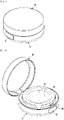
- the present invention relates generally to a foundation container having a discharge pump therein, in which a discharge plate above a container main body is pressed to discharge contents in the container main body by a pumping operation of a pump.
- the present invention relates to a foundation container having a discharge pump therein, in which contents are contained in a contents container of stretchable material inside the container main body, and the contents container is gradually compressed from an outer lower side to a center thereof by pumping operation of a pump to evenly distribute and discharge the contents, thereby minimizing the remaining amount of the contents compared to the conventional container.
- foundations are used for a base makeup and are used to make skin colors uniform and to cover defects. Foundations are classified into solid, liquid or gel types.
- the solid foundation has a good covering power, but it has a disadvantage that it is cakey during makeup correction.
- the liquid foundation has a good adhesion, but it has a weak sustainability.
- the gel foundation is conventionally contained in a glass container or a tube container, and is taken out to the user's hand or squeezed and applied to the skin with puff or by hand.
- a user should wash hands every time it is used.
- Patent Document 1 Korean Utility Model Registration No. 20-0470757
- a compact container having an airless pump which is configured such that between an outer container and a lid, a container main body, a pump, a discharge plate are coupled to each other, and the discharge plate is elastically pressed such that cosmetic contents in the container main body are pumped out and discharged to the discharge plate, and are used with a puff or the like, whereby there is no need to take out the contents by hand, and it is possible to easily carry the compact container.
- the conventional compact container having an airless pump is disadvantageous in that since, in order to effectively discharge the contents inside the the container main body during the pumping operation of the pump the container main body is provided with a piston at the inner bottom thereof, so that the piston is raised while discharging the contents during the pumping operation of the pump, in the case of the above piston type, the airtightness is deteriorated due to the horizontal disparity thereof, and it is difficult to discharge all the final residual contents, which lowers the user satisfaction considerably.
- the conventional compact container is further disadvantageous in that since a contents container of rubber material having elasticity is mounted in the container main body, the contents are discharged while the contents container is pressed during the pumping operation of the pump, the contents container has good airtightness but is not pressed evenly by the pumping force of the pump, and in particular, the contents container is pressed firstly around contents discharge holes, which interferes with the discharge of the contents, so that the discharge of the contents is not smooth, and it is difficult to discharge all the final residual contents, which lowers the user satisfaction considerably.
- the applicant of the present invention has sought to develop an improved product, which facilitates the discharge of contents, whereby a contents container is evenly compressed by the pumping operation of the pump to minimize the final residual contents, while using a contents container of rubber material having elasticity.
- US 2017/049213 A discloses a foundation container including a discharge pump having a short working stroke, the foundation container including an outer container main body; an outer container cap coupled to the outer container main body and opened/closed; a container main body coupled inside the outer container main body; and a container cap coupled to the upper portion of the container main body (30) and opened/closed.
- an object of the present invention is to provide a foundation container having a discharge pump therein, in which contents are contained in a contents container of stretchable material inside the container main body, and the contents container is gradually compressed from an outer lower side to a center thereof by pumping operation of a pump to evenly distribute and discharge the contents, thereby minimizing the remaining amount of the contents compared to the conventional container, and improving use efficiency.
- Another object of the present invention is to provide a foundation container having a discharge pump therein, in which a refill container, to which a container main body, a middle cap, a contents container, a pump, and a discharge plate are integrally coupled, is simply inserted into an outer container to enable refill use, whereby it is possible to improve economic feasibility and efficiency.
- a further object of the present invention is to provide a foundation container having a discharge pump therein, in which by a locking structure by a discharge plate, a stop portion, and a support portion of a middle cap, the pressing operation of the pump is not performed when initially used, and only after unlocking by rotating the discharge plate, the pumping operation is enabled by the pressing operation of the pump, whereby it is possible to prevent malfunctions.
- a foundation container having a discharge pump therein including: an outer container; a lid hinged to the outer container to be opened and closed vertically; a container main body mounted in the outer container; a pump coupled to an upper center portion of the container main body; and a discharge plate coupled to an upper portion of the pump, and formed with contents discharge holes, wherein the container main body is provided with a ventilation hole formed through a lower portion thereof, a contents container of stretchable material having a space portion for storing contents is inserted in the container main body, and an upper end of the contents container is seated on an upper portion of the container main body to be fixedly coupled by a middle cap coupled to the upper portion of the container main body, such that the contents container is gradually pressed by pumping operation of the pump by elastic pressing action of the discharge plate, so as to discharge the
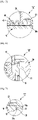
- the contents container is configured such that a lower edge thereof is provided with a rounded curved portion and a bottom thereof is provided with at least one annular bent portion formed to be bent upward and downward at a position outside a pump accommodating portion of a lower center portion of the middle cap, so as to induce the contents container to be gradually pressed from the rounded curved portion thereof.
- the contents container is provided on an upper bottom surface thereof with spaced protrusions protruding radially to form a gap for discharging the contents from an outer wall surface of the pump accommodating portion of the middle cap when the contents container is pressed.
- the outer container may be coupled to a coupling ring body to fix an inserted state of a button for opening and closing the lid in an assembly hole formed at a front of the outer container, wherein the coupling ring body is integrally provided at a back thereof with a slit cut in a circumferential direction, and a tension protrusion protruding from a center of the slit to provide a tension force at an initial stage of opening the lid.
- a distribution plate coupled to an upper portion of a piston rod of the pump may be provided at an upper portion thereof with branch passages formed radially at an equal angle interval from a contents supply hole at a center of the distribution plate to discharge the contents evenly to the discharge plate, each of the branch passages having a first branch passage for guiding discharge of the contents from the contents supply hole, and at least two second branch passages configured such that the second branch passages are branched in different directions at an end of the first branch passage to guide discharge of the contents and the contents discharge holes of the discharge plate are disposed to be aligned with end portions of the second branch passages.
- a refill container with the container main body, the middle cap, the contents container, the pump, and the discharge plate coupled thereto may be integrally provided and inserted in the outer container for refill use
- the outer container may be formed at a bottom thereof with an annular assembly hole, and a stop step having an inclined portion inclined from an upper portion to a lower portion thereof at an upper edge of the assembly hole
- the container main body may include: a ring-shaped coupling protrusion provided on an outer lower side thereof to be inserted into an assembly hole of the outer container to prevent separation, with a lower edge thereof formed with a rounded portion; and a seat protrusion provided at a position above the coupling protrusion to be seated in an inner bottom of the outer container.
- the outer container may be further provided with a knurling portion on a circumferential surface of an upper bottom thereof, and the seat protrusion of the container main body may be further provided with a support protrusion on a lower surface thereof to be engaged with the knurling portion to prevent rotation.
- the discharge plate may be provided on an outer side thereof radially at an equal angle interval with stop portions each having a stop protrusion at a lower portion of the outer side and a stop groove at a position above the stop protrusion
- the middle cap may be provided on an outer side thereof radially at an equal angle interval to correspond to the stop portions with support portions each having a lower support protrusion for supporting the stop protrusion of the discharge plate to restrict rotation of the stop protrusion toward lower and first sides thereof, an upper support protrusion for supporting an upper portion of the discharge plate, and a side support protrusion for engagement with the stop portion while being tensioned inward and outward by a slit formed on a second side thereof, whereby, at initial use, the stop portion of the discharge plate is forcibly rotated to be separated from the side support protrusion of the support portion, such that the discharge plate is released from a locked state to enable the pump to be operated.
- the contents container of stretchable material for storing cosmetic contents is coupled inside the container main body, and is fixed by the middle cap, and the contents container is provided with a rounded curved portion at a lower edge thereof, an annular bent portion bent upward and downward at a lower center portion thereof, and spaced protrusions protruding radially on an upper bottom surface, such that the contents container is evenly pressed from the rounded curved portion of the lower edge during the pumping operation of the pump, and even when the contents container is compressed, the gap is secured to discharge minimal contents, whereby the contents are smoothly discharged, and by the branch structure of the distribution plate and the discharge plate, it is possible to minimize the residual contents and improve use efficiency while discharging the cosmetic contents evenly.
- the present invention is advantageous in that a refill container, to which a container main body, a middle cap, a contents container, a pump, and a discharge plate are integrally coupled, is simply inserted into an outer container to enable refill use, whereby it is possible to improve economic feasibility and efficiency.
- a locking structure by a discharge plate, a stop portion, and a support portion of a middle cap the pressing operation of the pump is not performed when initially used, and only after unlocking by rotating the discharge plate, the pumping operation is enabled by the pressing operation of the pump, whereby it is possible to prevent malfunctions, and is possible to prevent contamination of the container and around the container due to cosmetic contents discharge by malfunction.
- a foundation container having a discharge pump therein of the present invention includes: an outer container 10; a lid 20 hinged to the outer container 10 to be opened and closed vertically; a container main body 30 mounted in the outer container 10; a pump 50 coupled to an upper center portion of the container main body 30; and a discharge plate 60 coupled to an upper portion of the pump 50 and formed with contents discharge holes 63.
- the container main body 30 is provided with a ventilation hole 31 formed through a lower portion thereof, a contents container 40 of stretchable material (for example, rubber materials such as urethane to prevent deterioration of cosmetic contents) having a space portion 41 for storing contents is inserted in the container main body, and an upper end of the contents container 40 is seated on an upper portion of the container main body to be fixedly coupled by a middle cap 35 coupled to the upper portion of the container main body, such that the contents container 40 is gradually pressed by pumping operation of the pump 50 by elastic pressing action of the discharge plate 60, so as to discharge the contents to the contents discharge holes 63 of the discharge plate.
- stretchable material for example, rubber materials such as urethane to prevent deterioration of cosmetic contents
- the contents container 40 is configured such that a lower edge thereof is provided with a rounded curved portion 42, and a bottom thereof is provided with at least one annular bent portion 43 formed to be bent upward and downward at a position outside a pump accommodating portion 36 of a lower center portion of the middle cap 35, so as to induce the contents container to be gradually pressed from the rounded curved portion of the contents container.
- the contents container 40 is provided on an upper bottom surface thereof with spaced protrusions 44 protruding radially to form a gap t for discharging the contents from an outer wall surface of the pump accommodating portion 36 of the middle cap when the contents container is pressed.
- the outer container 10 is coupled to a coupling ring body 15 to fix an inserted state of a button 12 for opening and closing the lid 20 in an assembly hole 11 formed at a front of the outer container.
- the button 12 is provided with right and left tension pieces 12a, a locking protrusion 12b protruding from an upper portion thereof to perform locking operation by being engaged with a locking groove 21 of the lid.
- the coupling ring body 15 is integrally provided at a back thereof with a slit 16 cut in a circumferential direction, and a tension protrusion 17 protruding from a center of the slit to provide a tension force at an initial stage of opening the lid 20, such that, compared to the conventional case where a tension protrusion is separately provided, it simplifies the structure and further improves tension operation by slit 16 space.
- the pump 50 includes: a check valve 51 configured to open and close a through-hole 36a formed through a bottom of the pump accommodating portion 36 at the lower center portion of the middle cap; a fixed piston 52 inside the pump accommodating portion; a piston rod 53 configured to open and close a discharge path of the cosmetic contents by vertically moving in the fixed piston; and a distribution plate 55 coupled to an upper portion of the piston rod to distribute the contents pumped out, wherein the distribution plate 55 is bonded to a coupling groove 65 formed in the lower portion of the discharge plate by ultrasonic bonding.
- the distribution plate 55 is provided at an upper portion thereof with branch passages 57 formed radially at an equal angle interval from a contents supply hole 56 at a center of the distribution plate to discharge the contents evenly to the discharge plate, each of the branch passages having a first branch passage 57a for guiding discharge of the contents, and at least two second branch passages 57b configured such that the second branch passages are branched in different directions at an end of the first branch passage to guide discharge of the contents and the contents discharge holes 63 of the discharge plate 60 are disposed to be aligned with end portions of the second branch passages.
- the container of the present invention is integrally provided with a refill container 100 coupled with the container main body 30, the middle cap 35, the contents container 40, the pump 50, and the discharge plate 60, for refill use by being inserted into the outer container 10.
- the outer container 10 is formed at a bottom thereof with an annular assembly hole 13, and a stop step 14 having an inclined portion 14a inclined from an upper portion to a lower portion thereof at an upper edge of the assembly hole.
- the container main body 30 includes: a ring-shaped coupling protrusion 32 provided on an outer lower side thereof to be inserted into the assembly hole 13 of the outer container to prevent separation, with a lower edge thereof formed with a rounded portion 32a; and a seat protrusion 33 provided at a position above the coupling protrusion to be seated in an inner bottom of the outer container.
- the outer container 10 may be further provided with a knurling portion 18 on a circumferential surface of an upper bottom thereof, and the seat protrusion 33 of the container main body 30 may be further provided with a support protrusion 34 on a lower surface thereof to be engaged with the knurling portion 18 to prevent rotation.
- the container of the present invention is configured such that, when initially provided, the pumping operation of the pump 50 by the discharge plate 60 is restricted by a locking structure to prevent malfunctions
- the locking structure is configured such that the discharge plate 60 is provided in an outer side thereof radially at an equal angle interval with stop portions 61 each having a stop protrusion 61a at a lower portion of the outer side and a stop groove 61b at a position above the stop protrusion
- the middle cap 35 is provided in an outer side thereof radially at an equal angle interval to correspond to the stop portion 61 with a support portion 37 having a lower support protrusion 37a for supporting the stop protrusion 61a of the discharge plate to restrict rotation toward lower and first sides thereof, an upper support protrusion 37b for supporting an upper portion of the discharge plate, and a side support protrusion 37c for engagement while being tensioned inward and outward by a slit 37d formed on a second side thereof, whereby, at initial use, the stop portion 61 of the discharge plate is
- the discharge plate 60 when the discharge plate 60 is forcibly rotated, the middle cap 35, the contents container 40, and the container main body 30 are prevented from being rotated by the knurling portion 18 of the outer container 10 and the support protrusion 34 of the container main body 30 being engaged with each other.
- reference numerals 71 and 72 denote an elastic spring
- reference numeral 80 denotes a puff
- the button 12 at the front of the outer container 10 is pressed to unlock the lid 20.
- the tension protrusion 17 of the coupling ring body 15 coupled to the inside of the outer container pushes the unlocked lid 20, and a user rotates the partially opened lid 20 to fully open the lid 20.
- the tension protrusion 17 of the coupling ring body 15 is operated by a simple structure integrally formed with the coupling ring body 15 instead of a conventional structure in which urethane rubber or the like is fitted separately, wherein the tension protrusion 17 is integrally protrudingly formed with the center of the slit 16 cut at the back of the coupling ring body in the circumferential direction to simplify the assembly structure, and also, the tension protrusion 17 is tensioned by the slit 16 to open the lid effectively at the initial stage of the opening.
- the discharge plate 60 is pressed by the puff 80 to enable the pump 50 to be operated.
- the discharge plate 60 is locked by the locking structure not to actuate pumping operation, whereby the discharge of the contents is prevented before the initial use.
- the locking structure of the discharge plate should be released at the initial use.
- the stop protrusion 61a of the discharge plate 60 is supported by being inserted into a space among the lower support protrusion 37a, the upper support protrusion 37b, and the side support protrusion 37c of the middle cap 35, the discharge plate is in the locked state where the downward movement and rotation of the discharge plate 60 are restricted, and in this state, the user forcibly rotates the discharge plate 60 in the direction of the side support protrusion 37c.
- the stop protrusion 61a of the discharge plate is rotated to be separated from the supported state, wherein since the upper support protrusion 37b inserted in the stop groove 61b of the discharge plate is rotated to the position where rotation is restricted, the lower portion of the stop protrusion 61a of the discharge plate is completely separated from the lower support protrusion 37a, so as to be in the unlocked state where elastic downward movement is possible.
- the discharge plate 60 when the discharge plate 60 is forcibly rotated, the middle cap 35, the contents container 40, and the container main body 30 are prevented from being rotated since the knurling portion 18 of the outer container and the support protrusion 34 of the container main body are engaged with each other.
- the discharge plate 60 is elastically pressed along with the puff 80 to enable the pump 50 to be operated, and thus, the cosmetic contents contained in the contents container 40 inside the container main body is discharged to be used.
- the check valve 51 opens the through-hole 36a formed through the bottom of the pump accommodating portion 36, and the contents container 40 inside the container main body is pressed to discharge the contents, whereby the contents are discharged to the distribution plate 55 and the discharge plate 60 through the through-hole 36a and the discharge path of the pump.
- the contents container 40 inside the container main body is made of stretchable material to be compressed by the pumping force of the pump, wherein the bottom of the contents container 40 is provided with the annular bent portion 43 formed to be bent upward and downward at a position outside the pump accommodating portion 36 of the lower center portion of the middle cap 35, and the lower edge thereof is provided with the rounded curved portion 42, whereby the contents are discharged while gradually inducing to be pressed from the rounded curved portion 42 of the lower edge rather than the central position where the bent portion of the contents container is formed.
- the cosmetic contents of the contents container are induced to be pressed evenly and the discharge is induced.
- the contents container 40 is provided on the upper bottom surface thereof with the spaced protrusions 44 protruding radially, even when the bottom surface is pressed to be brought into close contact with the outer wall surface of the pump accommodating portion 36 of the middle cap, the gap t is provided between the contents container and the outer wall of the pump accommodating portion by the spaced protrusions, so that the final residual contents are induced to be smoothly discharged.
- the contents discharged by the pumping operation of the pump are discharged to the first branch passage 57a of the branch passage formed radially from the contents supply hole, and to the second branch passages 57b configured such that the second branch passages are branched in different directions at the end of the first branch passage, through the contents supply hole 56 at the center of the distribution plate 55 of the pump, and then at the end of the second branch passage, the contents are distributed and discharged to the contents discharge holes 63 of the discharge plate, whereby the cosmetic contents are evenly distributed and smeared on the entire lower portion of the puff 80 to be used.
- the cosmetic contents are evenly smeared on the entire lower portion of the puff 80, so that the makeup application can be performed more efficiently.
- the refill container 100 to which the container main body 30, the middle cap 35, the contents container 40, pump 50, and the discharge plate 60 are integrally coupled, can be coupled to the inside of the outer container 10 for refill use.
- the refill container 100 to which the container main body 30, the middle cap 35, the contents container 40, pump 50, and the discharge plate 60 are integrally coupled, is inserted from the upper portion of the outer container 10 to the inside thereof.
- the seat protrusion 33 of the container main body is seated in the inner bottom of the outer container 10, whereby the coupling protrusion 32 is inserted into the assembly hole 13, and thus, the refill container is assembled to be prevented from separation by the stop step 14 and is reusable as described above.
Landscapes
- Engineering & Computer Science (AREA)
- Mechanical Engineering (AREA)
- Containers And Packaging Bodies Having A Special Means To Remove Contents (AREA)
- Closures For Containers (AREA)
Applications Claiming Priority (2)
| Application Number | Priority Date | Filing Date | Title |
|---|---|---|---|
| KR1020180077413A KR101915937B1 (ko) | 2018-07-04 | 2018-07-04 | 배출 펌프 내장형 파운데이션 용기 |
| PCT/KR2018/015417 WO2020009289A1 (en) | 2018-07-04 | 2018-12-06 | Foundation container having discharge pump therein |
Publications (3)
| Publication Number | Publication Date |
|---|---|
| EP3675685A1 EP3675685A1 (en) | 2020-07-08 |
| EP3675685A4 EP3675685A4 (en) | 2020-09-30 |
| EP3675685B1 true EP3675685B1 (en) | 2022-08-03 |
Family
ID=64329684
Family Applications (1)
| Application Number | Title | Priority Date | Filing Date |
|---|---|---|---|
| EP18925470.9A Active EP3675685B1 (en) | 2018-07-04 | 2018-12-06 | Foundation container having discharge pump therein |
Country Status (6)
| Country | Link |
|---|---|
| US (1) | US11337503B2 (zh) |
| EP (1) | EP3675685B1 (zh) |
| JP (1) | JP6934689B2 (zh) |
| KR (1) | KR101915937B1 (zh) |
| CN (1) | CN110891455B (zh) |
| WO (1) | WO2020009289A1 (zh) |
Families Citing this family (8)
| Publication number | Priority date | Publication date | Assignee | Title |
|---|---|---|---|---|
| KR101915937B1 (ko) * | 2018-07-04 | 2018-11-06 | 김진우 | 배출 펌프 내장형 파운데이션 용기 |
| KR102188196B1 (ko) * | 2019-04-15 | 2020-12-09 | 주식회사 삼화 | 화장품 용기 |
| CN210213332U (zh) * | 2019-05-14 | 2020-03-31 | 上海爱派娅科技有限公司 | 一种按压式化妆瓶 |
| CN210630798U (zh) | 2019-06-24 | 2020-05-29 | 上海爱派娅科技有限公司 | 一种按钮式唇彩管 |
| KR102212050B1 (ko) * | 2019-12-03 | 2021-02-04 | 주식회사 월드스폰지 | 펌핑구조가 구비된 파우더용 화장품 용기 |
| USD933301S1 (en) * | 2020-02-28 | 2021-10-12 | Pum-Tech Korea Co., Ltd | Compact container |
| USD933300S1 (en) * | 2020-02-28 | 2021-10-12 | Pum-Tech Korea Co., Ltd | Compact container |
| KR102573559B1 (ko) * | 2022-04-08 | 2023-09-01 | 주식회사 탭코리아 | 에어리스 펌프를 가지는 콤팩트 화장품용기 |
Family Cites Families (21)
| Publication number | Priority date | Publication date | Assignee | Title |
|---|---|---|---|---|
| US5411182A (en) * | 1993-04-19 | 1995-05-02 | Colgate-Palmolive Co. | Dispensing device for viscous materials |
| FR2903092B1 (fr) * | 2006-07-03 | 2008-10-17 | Airlessystems Soc Par Actions | Distributeur de produit fluide |
| KR101378521B1 (ko) * | 2012-10-29 | 2014-03-27 | 변재삼 | 기밀 화장품용기 |
| KR101403741B1 (ko) | 2012-12-14 | 2014-06-03 | 오세웅 | 화장품 용기 |
| KR200470757Y1 (ko) | 2013-06-18 | 2014-01-09 | (주)아모레퍼시픽 | 혼합부재를 구비한 에어리스펌프를 갖는 콤팩트 용기 |
| KR200477829Y1 (ko) * | 2013-09-24 | 2015-08-06 | 강성일 | 행정거리가 짧은 배출펌프와 내용물 확산부재를 구비한 파운데이션 용기 |
| KR200480194Y1 (ko) | 2013-12-12 | 2016-04-22 | 강성일 | 배출펌프를 구비한 파운데이션 용기 |
| KR102071998B1 (ko) * | 2014-02-14 | 2020-02-03 | 주식회사 엘지생활건강 | 화장품 용기 |
| KR200481481Y1 (ko) | 2014-09-05 | 2016-10-06 | 강성일 | 펌프가 구비된 겔상 파운데이션 용기 |
| KR200479429Y1 (ko) * | 2014-09-05 | 2016-02-12 | 강성일 | 가압이 편리한 펌프를 구비한 파운데이션 용기 |
| KR200483846Y1 (ko) | 2014-12-12 | 2017-07-11 | 강성일 | 메시망을 구비한 겔상 화장료용 콤팩트 용기 |
| KR101663782B1 (ko) * | 2015-01-29 | 2016-10-10 | 주식회사 케이알 | 펌프식 화장품 용기 |
| KR101730441B1 (ko) * | 2015-08-03 | 2017-04-27 | 펌텍코리아 (주) | 행정거리가 짧은 펌프와 링버튼부재를 구비한 콤팩트 용기 |
| US10857554B2 (en) * | 2015-08-27 | 2020-12-08 | Pum-Tech Korea Co., Ltd. | Compact container including pump having short stroke |
| KR200486987Y1 (ko) * | 2016-04-28 | 2018-07-23 | 주식회사 엘지생활건강 | 화장품 용기 |
| US20170318938A1 (en) * | 2016-05-09 | 2017-11-09 | Pum-Tech Korea Co., Ltd | Compact container having insert-molded discharge plate supported by fixing member |
| KR20180012517A (ko) * | 2016-07-27 | 2018-02-06 | (주)연우 | 크림타입 화장품 용기의 씰링구조 |
| KR101897954B1 (ko) * | 2016-07-28 | 2018-09-14 | 펌텍코리아(주) | 링버튼부재가 구비되고 배출판이 인서트 사출된 콤팩트 용기 |
| KR101796899B1 (ko) * | 2017-07-10 | 2017-11-10 | 김석린 | 화장품 용기 |
| KR101942665B1 (ko) * | 2017-10-17 | 2019-01-25 | 옴니시스템 주식회사 | 토출구가 형성된 가압 플레이트를 갖는 콤팩트형 화장품 케이스 |
| KR101915937B1 (ko) | 2018-07-04 | 2018-11-06 | 김진우 | 배출 펌프 내장형 파운데이션 용기 |
-
2018
- 2018-07-04 KR KR1020180077413A patent/KR101915937B1/ko active IP Right Grant
- 2018-12-06 JP JP2020506352A patent/JP6934689B2/ja active Active
- 2018-12-06 EP EP18925470.9A patent/EP3675685B1/en active Active
- 2018-12-06 CN CN201880047357.1A patent/CN110891455B/zh active Active
- 2018-12-06 WO PCT/KR2018/015417 patent/WO2020009289A1/en unknown
- 2018-12-06 US US16/634,670 patent/US11337503B2/en active Active
Also Published As
| Publication number | Publication date |
|---|---|
| EP3675685A4 (en) | 2020-09-30 |
| US20200205544A1 (en) | 2020-07-02 |
| KR101915937B1 (ko) | 2018-11-06 |
| CN110891455A (zh) | 2020-03-17 |
| JP2020537548A (ja) | 2020-12-24 |
| JP6934689B2 (ja) | 2021-09-15 |
| WO2020009289A1 (en) | 2020-01-09 |
| US11337503B2 (en) | 2022-05-24 |
| CN110891455B (zh) | 2022-03-04 |
| EP3675685A1 (en) | 2020-07-08 |
Similar Documents
| Publication | Publication Date | Title |
|---|---|---|
| EP3675685B1 (en) | Foundation container having discharge pump therein | |
| EP3419473B1 (en) | Push type cosmetic container | |
| JP6514339B2 (ja) | リングボタン部材を備えたコンパクト容器 | |
| KR101715180B1 (ko) | 화장품 용기 | |
| KR101777317B1 (ko) | 리필용기가 구비된 화장품 용기 | |
| KR101527758B1 (ko) | 에어리스 콤팩트 용기 | |
| US20170095055A1 (en) | Compact using applicator as pushbutton | |
| KR101663782B1 (ko) | 펌프식 화장품 용기 | |
| JP2021010737A (ja) | 便利なリフィル構造を有する化粧品容器 | |
| KR200479429Y1 (ko) | 가압이 편리한 펌프를 구비한 파운데이션 용기 | |
| KR101521396B1 (ko) | 밀폐식 액상 콤팩트 용기 | |
| KR200489985Y1 (ko) | 화장품 용기 | |
| KR101535087B1 (ko) | 펌프 타입 콤팩트 용기 | |
| KR200464876Y1 (ko) | 진동수단이 구비된 펌프형 마사지 용기 | |
| KR101661581B1 (ko) | 펌프 타입 콤팩트 용기 | |
| KR101689389B1 (ko) | 펌프 타입 콤팩트 용기 | |
| JP6676818B1 (ja) | 化粧品容器 | |
| US20210378382A1 (en) | Grinding powder refill cosmetic container | |
| KR20190001535U (ko) | 화장품 용기 | |
| KR101784737B1 (ko) | 탄성 재질의 내용물용기가 구비된 화장품 용기 | |
| US8602671B2 (en) | Cosmetics container with a puff rotatably mounted on a container body | |
| KR200471504Y1 (ko) | 색조화장품 수납용 복합용기 | |
| KR200494911Y1 (ko) | 화장품 용기 | |
| KR101902268B1 (ko) | 에어리스 펌프를 가지는 콤팩트 화장품용기 | |
| KR101729072B1 (ko) | 자동으로 개방되는 뚜껑을 구비한 펌핑 파운데이션 용기 |
Legal Events
| Date | Code | Title | Description |
|---|---|---|---|
| STAA | Information on the status of an ep patent application or granted ep patent |
Free format text: STATUS: THE INTERNATIONAL PUBLICATION HAS BEEN MADE |
|
| PUAI | Public reference made under article 153(3) epc to a published international application that has entered the european phase |
Free format text: ORIGINAL CODE: 0009012 |
|
| STAA | Information on the status of an ep patent application or granted ep patent |
Free format text: STATUS: REQUEST FOR EXAMINATION WAS MADE |
|
| 17P | Request for examination filed |
Effective date: 20200331 |
|
| AK | Designated contracting states |
Kind code of ref document: A1 Designated state(s): AL AT BE BG CH CY CZ DE DK EE ES FI FR GB GR HR HU IE IS IT LI LT LU LV MC MK MT NL NO PL PT RO RS SE SI SK SM TR |
|
| AX | Request for extension of the european patent |
Extension state: BA ME |
|
| A4 | Supplementary search report drawn up and despatched |
Effective date: 20200827 |
|
| RIC1 | Information provided on ipc code assigned before grant |
Ipc: A45D 34/04 20060101AFI20200821BHEP Ipc: A45D 33/00 20060101ALI20200821BHEP Ipc: A45D 40/26 20060101ALI20200821BHEP Ipc: A45D 40/22 20060101ALI20200821BHEP Ipc: B65D 43/16 20060101ALI20200821BHEP Ipc: A45D 40/00 20060101ALI20200821BHEP Ipc: A45D 34/00 20060101ALI20200821BHEP Ipc: A45D 33/06 20060101ALI20200821BHEP |
|
| DAV | Request for validation of the european patent (deleted) | ||
| DAX | Request for extension of the european patent (deleted) | ||
| RIC1 | Information provided on ipc code assigned before grant |
Ipc: A45D 33/00 20060101ALI20220228BHEP Ipc: A45D 33/06 20060101ALI20220228BHEP Ipc: A45D 34/00 20060101ALI20220228BHEP Ipc: A45D 40/00 20060101ALI20220228BHEP Ipc: A45D 40/22 20060101ALI20220228BHEP Ipc: B65D 43/16 20060101ALI20220228BHEP Ipc: A45D 40/26 20060101ALI20220228BHEP Ipc: A45D 34/04 20060101AFI20220228BHEP |
|
| GRAP | Despatch of communication of intention to grant a patent |
Free format text: ORIGINAL CODE: EPIDOSNIGR1 |
|
| STAA | Information on the status of an ep patent application or granted ep patent |
Free format text: STATUS: GRANT OF PATENT IS INTENDED |
|
| INTG | Intention to grant announced |
Effective date: 20220412 |
|
| GRAS | Grant fee paid |
Free format text: ORIGINAL CODE: EPIDOSNIGR3 |
|
| GRAA | (expected) grant |
Free format text: ORIGINAL CODE: 0009210 |
|
| STAA | Information on the status of an ep patent application or granted ep patent |
Free format text: STATUS: THE PATENT HAS BEEN GRANTED |
|
| AK | Designated contracting states |
Kind code of ref document: B1 Designated state(s): AL AT BE BG CH CY CZ DE DK EE ES FI FR GB GR HR HU IE IS IT LI LT LU LV MC MK MT NL NO PL PT RO RS SE SI SK SM TR |
|
| REG | Reference to a national code |
Ref country code: AT Ref legal event code: REF Ref document number: 1508050 Country of ref document: AT Kind code of ref document: T Effective date: 20220815 Ref country code: CH Ref legal event code: EP |
|
| REG | Reference to a national code |
Ref country code: DE Ref legal event code: R096 Ref document number: 602018038949 Country of ref document: DE |
|
| REG | Reference to a national code |
Ref country code: IE Ref legal event code: FG4D |
|
| REG | Reference to a national code |
Ref country code: LT Ref legal event code: MG9D |
|
| REG | Reference to a national code |
Ref country code: NL Ref legal event code: MP Effective date: 20220803 |
|
| PG25 | Lapsed in a contracting state [announced via postgrant information from national office to epo] |
Ref country code: SE Free format text: LAPSE BECAUSE OF FAILURE TO SUBMIT A TRANSLATION OF THE DESCRIPTION OR TO PAY THE FEE WITHIN THE PRESCRIBED TIME-LIMIT Effective date: 20220803 Ref country code: RS Free format text: LAPSE BECAUSE OF FAILURE TO SUBMIT A TRANSLATION OF THE DESCRIPTION OR TO PAY THE FEE WITHIN THE PRESCRIBED TIME-LIMIT Effective date: 20220803 Ref country code: PT Free format text: LAPSE BECAUSE OF FAILURE TO SUBMIT A TRANSLATION OF THE DESCRIPTION OR TO PAY THE FEE WITHIN THE PRESCRIBED TIME-LIMIT Effective date: 20221205 Ref country code: NO Free format text: LAPSE BECAUSE OF FAILURE TO SUBMIT A TRANSLATION OF THE DESCRIPTION OR TO PAY THE FEE WITHIN THE PRESCRIBED TIME-LIMIT Effective date: 20221103 Ref country code: NL Free format text: LAPSE BECAUSE OF FAILURE TO SUBMIT A TRANSLATION OF THE DESCRIPTION OR TO PAY THE FEE WITHIN THE PRESCRIBED TIME-LIMIT Effective date: 20220803 Ref country code: LV Free format text: LAPSE BECAUSE OF FAILURE TO SUBMIT A TRANSLATION OF THE DESCRIPTION OR TO PAY THE FEE WITHIN THE PRESCRIBED TIME-LIMIT Effective date: 20220803 Ref country code: LT Free format text: LAPSE BECAUSE OF FAILURE TO SUBMIT A TRANSLATION OF THE DESCRIPTION OR TO PAY THE FEE WITHIN THE PRESCRIBED TIME-LIMIT Effective date: 20220803 Ref country code: FI Free format text: LAPSE BECAUSE OF FAILURE TO SUBMIT A TRANSLATION OF THE DESCRIPTION OR TO PAY THE FEE WITHIN THE PRESCRIBED TIME-LIMIT Effective date: 20220803 Ref country code: ES Free format text: LAPSE BECAUSE OF FAILURE TO SUBMIT A TRANSLATION OF THE DESCRIPTION OR TO PAY THE FEE WITHIN THE PRESCRIBED TIME-LIMIT Effective date: 20220803 |
|
| REG | Reference to a national code |
Ref country code: AT Ref legal event code: MK05 Ref document number: 1508050 Country of ref document: AT Kind code of ref document: T Effective date: 20220803 |
|
| PG25 | Lapsed in a contracting state [announced via postgrant information from national office to epo] |
Ref country code: PL Free format text: LAPSE BECAUSE OF FAILURE TO SUBMIT A TRANSLATION OF THE DESCRIPTION OR TO PAY THE FEE WITHIN THE PRESCRIBED TIME-LIMIT Effective date: 20220803 Ref country code: IS Free format text: LAPSE BECAUSE OF FAILURE TO SUBMIT A TRANSLATION OF THE DESCRIPTION OR TO PAY THE FEE WITHIN THE PRESCRIBED TIME-LIMIT Effective date: 20221203 Ref country code: HR Free format text: LAPSE BECAUSE OF FAILURE TO SUBMIT A TRANSLATION OF THE DESCRIPTION OR TO PAY THE FEE WITHIN THE PRESCRIBED TIME-LIMIT Effective date: 20220803 Ref country code: GR Free format text: LAPSE BECAUSE OF FAILURE TO SUBMIT A TRANSLATION OF THE DESCRIPTION OR TO PAY THE FEE WITHIN THE PRESCRIBED TIME-LIMIT Effective date: 20221104 |
|
| PG25 | Lapsed in a contracting state [announced via postgrant information from national office to epo] |
Ref country code: SM Free format text: LAPSE BECAUSE OF FAILURE TO SUBMIT A TRANSLATION OF THE DESCRIPTION OR TO PAY THE FEE WITHIN THE PRESCRIBED TIME-LIMIT Effective date: 20220803 Ref country code: RO Free format text: LAPSE BECAUSE OF FAILURE TO SUBMIT A TRANSLATION OF THE DESCRIPTION OR TO PAY THE FEE WITHIN THE PRESCRIBED TIME-LIMIT Effective date: 20220803 Ref country code: DK Free format text: LAPSE BECAUSE OF FAILURE TO SUBMIT A TRANSLATION OF THE DESCRIPTION OR TO PAY THE FEE WITHIN THE PRESCRIBED TIME-LIMIT Effective date: 20220803 Ref country code: CZ Free format text: LAPSE BECAUSE OF FAILURE TO SUBMIT A TRANSLATION OF THE DESCRIPTION OR TO PAY THE FEE WITHIN THE PRESCRIBED TIME-LIMIT Effective date: 20220803 Ref country code: AT Free format text: LAPSE BECAUSE OF FAILURE TO SUBMIT A TRANSLATION OF THE DESCRIPTION OR TO PAY THE FEE WITHIN THE PRESCRIBED TIME-LIMIT Effective date: 20220803 |
|
| REG | Reference to a national code |
Ref country code: DE Ref legal event code: R097 Ref document number: 602018038949 Country of ref document: DE |
|
| PG25 | Lapsed in a contracting state [announced via postgrant information from national office to epo] |
Ref country code: SK Free format text: LAPSE BECAUSE OF FAILURE TO SUBMIT A TRANSLATION OF THE DESCRIPTION OR TO PAY THE FEE WITHIN THE PRESCRIBED TIME-LIMIT Effective date: 20220803 Ref country code: EE Free format text: LAPSE BECAUSE OF FAILURE TO SUBMIT A TRANSLATION OF THE DESCRIPTION OR TO PAY THE FEE WITHIN THE PRESCRIBED TIME-LIMIT Effective date: 20220803 |
|
| PLBE | No opposition filed within time limit |
Free format text: ORIGINAL CODE: 0009261 |
|
| STAA | Information on the status of an ep patent application or granted ep patent |
Free format text: STATUS: NO OPPOSITION FILED WITHIN TIME LIMIT |
|
| PG25 | Lapsed in a contracting state [announced via postgrant information from national office to epo] |
Ref country code: AL Free format text: LAPSE BECAUSE OF FAILURE TO SUBMIT A TRANSLATION OF THE DESCRIPTION OR TO PAY THE FEE WITHIN THE PRESCRIBED TIME-LIMIT Effective date: 20220803 |
|
| 26N | No opposition filed |
Effective date: 20230504 |
|
| REG | Reference to a national code |
Ref country code: CH Ref legal event code: PL |
|
| REG | Reference to a national code |
Ref country code: BE Ref legal event code: MM Effective date: 20221231 |
|
| PG25 | Lapsed in a contracting state [announced via postgrant information from national office to epo] |
Ref country code: SI Free format text: LAPSE BECAUSE OF FAILURE TO SUBMIT A TRANSLATION OF THE DESCRIPTION OR TO PAY THE FEE WITHIN THE PRESCRIBED TIME-LIMIT Effective date: 20220803 Ref country code: LU Free format text: LAPSE BECAUSE OF NON-PAYMENT OF DUE FEES Effective date: 20221206 |
|
| PG25 | Lapsed in a contracting state [announced via postgrant information from national office to epo] |
Ref country code: LI Free format text: LAPSE BECAUSE OF NON-PAYMENT OF DUE FEES Effective date: 20221231 Ref country code: IE Free format text: LAPSE BECAUSE OF NON-PAYMENT OF DUE FEES Effective date: 20221206 Ref country code: CH Free format text: LAPSE BECAUSE OF NON-PAYMENT OF DUE FEES Effective date: 20221231 |
|
| PG25 | Lapsed in a contracting state [announced via postgrant information from national office to epo] |
Ref country code: BE Free format text: LAPSE BECAUSE OF NON-PAYMENT OF DUE FEES Effective date: 20221231 |
|
| PGFP | Annual fee paid to national office [announced via postgrant information from national office to epo] |
Ref country code: GB Payment date: 20231124 Year of fee payment: 6 |
|
| PGFP | Annual fee paid to national office [announced via postgrant information from national office to epo] |
Ref country code: FR Payment date: 20231122 Year of fee payment: 6 Ref country code: DE Payment date: 20231121 Year of fee payment: 6 |
|
| PG25 | Lapsed in a contracting state [announced via postgrant information from national office to epo] |
Ref country code: HU Free format text: LAPSE BECAUSE OF FAILURE TO SUBMIT A TRANSLATION OF THE DESCRIPTION OR TO PAY THE FEE WITHIN THE PRESCRIBED TIME-LIMIT; INVALID AB INITIO Effective date: 20181206 |
|
| PG25 | Lapsed in a contracting state [announced via postgrant information from national office to epo] |
Ref country code: CY Free format text: LAPSE BECAUSE OF FAILURE TO SUBMIT A TRANSLATION OF THE DESCRIPTION OR TO PAY THE FEE WITHIN THE PRESCRIBED TIME-LIMIT Effective date: 20220803 |
|
| PG25 | Lapsed in a contracting state [announced via postgrant information from national office to epo] |
Ref country code: MK Free format text: LAPSE BECAUSE OF FAILURE TO SUBMIT A TRANSLATION OF THE DESCRIPTION OR TO PAY THE FEE WITHIN THE PRESCRIBED TIME-LIMIT Effective date: 20220803 Ref country code: IT Free format text: LAPSE BECAUSE OF FAILURE TO SUBMIT A TRANSLATION OF THE DESCRIPTION OR TO PAY THE FEE WITHIN THE PRESCRIBED TIME-LIMIT Effective date: 20220803 |
|
| PG25 | Lapsed in a contracting state [announced via postgrant information from national office to epo] |
Ref country code: MC Free format text: LAPSE BECAUSE OF FAILURE TO SUBMIT A TRANSLATION OF THE DESCRIPTION OR TO PAY THE FEE WITHIN THE PRESCRIBED TIME-LIMIT Effective date: 20220803 |
|
| PG25 | Lapsed in a contracting state [announced via postgrant information from national office to epo] |
Ref country code: TR Free format text: LAPSE BECAUSE OF FAILURE TO SUBMIT A TRANSLATION OF THE DESCRIPTION OR TO PAY THE FEE WITHIN THE PRESCRIBED TIME-LIMIT Effective date: 20220803 Ref country code: MC Free format text: LAPSE BECAUSE OF FAILURE TO SUBMIT A TRANSLATION OF THE DESCRIPTION OR TO PAY THE FEE WITHIN THE PRESCRIBED TIME-LIMIT Effective date: 20220803 |
|
| PG25 | Lapsed in a contracting state [announced via postgrant information from national office to epo] |
Ref country code: BG Free format text: LAPSE BECAUSE OF FAILURE TO SUBMIT A TRANSLATION OF THE DESCRIPTION OR TO PAY THE FEE WITHIN THE PRESCRIBED TIME-LIMIT Effective date: 20220803 |