EP3675659B1 - Smoking article and method for cooling a heated particle-loaded gas - Google Patents
Smoking article and method for cooling a heated particle-loaded gas Download PDFInfo
- Publication number
- EP3675659B1 EP3675659B1 EP18762025.7A EP18762025A EP3675659B1 EP 3675659 B1 EP3675659 B1 EP 3675659B1 EP 18762025 A EP18762025 A EP 18762025A EP 3675659 B1 EP3675659 B1 EP 3675659B1
- Authority
- EP
- European Patent Office
- Prior art keywords
- cooling
- particle
- smoking article
- loaded gas
- endothermic process
- Prior art date
- Legal status (The legal status is an assumption and is not a legal conclusion. Google has not performed a legal analysis and makes no representation as to the accuracy of the status listed.)
- Active
Links
- 238000001816 cooling Methods 0.000 title claims description 137
- 230000000391 smoking effect Effects 0.000 title claims description 54
- 238000000034 method Methods 0.000 title claims description 43
- 239000002245 particle Substances 0.000 title claims description 27
- 239000000463 material Substances 0.000 claims description 69
- 239000012876 carrier material Substances 0.000 claims description 44
- XLYOFNOQVPJJNP-UHFFFAOYSA-N water Substances O XLYOFNOQVPJJNP-UHFFFAOYSA-N 0.000 claims description 10
- 230000008018 melting Effects 0.000 claims description 6
- 238000002844 melting Methods 0.000 claims description 6
- 238000003795 desorption Methods 0.000 claims description 5
- 229910017053 inorganic salt Inorganic materials 0.000 claims description 4
- 230000008016 vaporization Effects 0.000 claims description 4
- 238000002425 crystallisation Methods 0.000 claims description 3
- 230000008025 crystallization Effects 0.000 claims description 3
- 239000007789 gas Substances 0.000 description 58
- 241000208125 Nicotiana Species 0.000 description 20
- 235000002637 Nicotiana tabacum Nutrition 0.000 description 20
- 235000019504 cigarettes Nutrition 0.000 description 12
- 239000000779 smoke Substances 0.000 description 11
- 239000007788 liquid Substances 0.000 description 8
- 239000000126 substance Substances 0.000 description 8
- 239000013078 crystal Substances 0.000 description 4
- 239000000203 mixture Substances 0.000 description 4
- 239000007787 solid Substances 0.000 description 4
- CSNNHWWHGAXBCP-UHFFFAOYSA-L Magnesium sulfate Chemical compound [Mg+2].[O-][S+2]([O-])([O-])[O-] CSNNHWWHGAXBCP-UHFFFAOYSA-L 0.000 description 3
- 238000002485 combustion reaction Methods 0.000 description 3
- 239000003571 electronic cigarette Substances 0.000 description 3
- 238000009834 vaporization Methods 0.000 description 3
- OKTJSMMVPCPJKN-UHFFFAOYSA-N Carbon Chemical compound [C] OKTJSMMVPCPJKN-UHFFFAOYSA-N 0.000 description 2
- 229920000742 Cotton Polymers 0.000 description 2
- PMZURENOXWZQFD-UHFFFAOYSA-L Sodium Sulfate Chemical compound [Na+].[Na+].[O-]S([O-])(=O)=O PMZURENOXWZQFD-UHFFFAOYSA-L 0.000 description 2
- 239000000443 aerosol Substances 0.000 description 2
- 239000002826 coolant Substances 0.000 description 2
- 230000000694 effects Effects 0.000 description 2
- 239000003344 environmental pollutant Substances 0.000 description 2
- 238000001704 evaporation Methods 0.000 description 2
- 238000004519 manufacturing process Methods 0.000 description 2
- 231100000719 pollutant Toxicity 0.000 description 2
- 150000003839 salts Chemical class 0.000 description 2
- 229920001131 Pulp (paper) Polymers 0.000 description 1
- VYPSYNLAJGMNEJ-UHFFFAOYSA-N Silicium dioxide Chemical compound O=[Si]=O VYPSYNLAJGMNEJ-UHFFFAOYSA-N 0.000 description 1
- 229910021536 Zeolite Inorganic materials 0.000 description 1
- 238000004220 aggregation Methods 0.000 description 1
- 230000002776 aggregation Effects 0.000 description 1
- 230000015572 biosynthetic process Effects 0.000 description 1
- 238000009835 boiling Methods 0.000 description 1
- 239000002775 capsule Substances 0.000 description 1
- 229920002301 cellulose acetate Polymers 0.000 description 1
- HNPSIPDUKPIQMN-UHFFFAOYSA-N dioxosilane;oxo(oxoalumanyloxy)alumane Chemical compound O=[Si]=O.O=[Al]O[Al]=O HNPSIPDUKPIQMN-UHFFFAOYSA-N 0.000 description 1
- HFCSXCKLARAMIQ-UHFFFAOYSA-L disodium;sulfate;hydrate Chemical compound O.[Na+].[Na+].[O-]S([O-])(=O)=O HFCSXCKLARAMIQ-UHFFFAOYSA-L 0.000 description 1
- 238000009826 distribution Methods 0.000 description 1
- 230000009977 dual effect Effects 0.000 description 1
- 230000008020 evaporation Effects 0.000 description 1
- 239000000945 filler Substances 0.000 description 1
- 238000001914 filtration Methods 0.000 description 1
- 239000003365 glass fiber Substances 0.000 description 1
- 230000036571 hydration Effects 0.000 description 1
- 238000006703 hydration reaction Methods 0.000 description 1
- 229910052739 hydrogen Inorganic materials 0.000 description 1
- 239000001257 hydrogen Substances 0.000 description 1
- 150000002500 ions Chemical group 0.000 description 1
- 229910052943 magnesium sulfate Inorganic materials 0.000 description 1
- 235000019341 magnesium sulphate Nutrition 0.000 description 1
- 239000000155 melt Substances 0.000 description 1
- 239000010446 mirabilite Substances 0.000 description 1
- 239000003595 mist Substances 0.000 description 1
- 230000035699 permeability Effects 0.000 description 1
- 231100000614 poison Toxicity 0.000 description 1
- 239000011148 porous material Substances 0.000 description 1
- 239000000843 powder Substances 0.000 description 1
- 239000000741 silica gel Substances 0.000 description 1
- 229910002027 silica gel Inorganic materials 0.000 description 1
- 229910052938 sodium sulfate Inorganic materials 0.000 description 1
- RSIJVJUOQBWMIM-UHFFFAOYSA-L sodium sulfate decahydrate Chemical compound O.O.O.O.O.O.O.O.O.O.[Na+].[Na+].[O-]S([O-])(=O)=O RSIJVJUOQBWMIM-UHFFFAOYSA-L 0.000 description 1
- 235000011152 sodium sulphate Nutrition 0.000 description 1
- 229910001220 stainless steel Inorganic materials 0.000 description 1
- 239000010935 stainless steel Substances 0.000 description 1
- 238000005979 thermal decomposition reaction Methods 0.000 description 1
- 239000003440 toxic substance Substances 0.000 description 1
- 239000006200 vaporizer Substances 0.000 description 1
- 239000010457 zeolite Substances 0.000 description 1
Images
Classifications
-
- A—HUMAN NECESSITIES
- A24—TOBACCO; CIGARS; CIGARETTES; SIMULATED SMOKING DEVICES; SMOKERS' REQUISITES
- A24D—CIGARS; CIGARETTES; TOBACCO SMOKE FILTERS; MOUTHPIECES FOR CIGARS OR CIGARETTES; MANUFACTURE OF TOBACCO SMOKE FILTERS OR MOUTHPIECES
- A24D3/00—Tobacco smoke filters, e.g. filter-tips, filtering inserts; Filters specially adapted for simulated smoking devices; Mouthpieces for cigars or cigarettes
- A24D3/04—Tobacco smoke filters characterised by their shape or structure
- A24D3/048—Tobacco smoke filters characterised by their shape or structure containing additives
-
- A—HUMAN NECESSITIES
- A24—TOBACCO; CIGARS; CIGARETTES; SIMULATED SMOKING DEVICES; SMOKERS' REQUISITES
- A24D—CIGARS; CIGARETTES; TOBACCO SMOKE FILTERS; MOUTHPIECES FOR CIGARS OR CIGARETTES; MANUFACTURE OF TOBACCO SMOKE FILTERS OR MOUTHPIECES
- A24D3/00—Tobacco smoke filters, e.g. filter-tips, filtering inserts; Filters specially adapted for simulated smoking devices; Mouthpieces for cigars or cigarettes
- A24D3/17—Filters specially adapted for simulated smoking devices
-
- A—HUMAN NECESSITIES
- A24—TOBACCO; CIGARS; CIGARETTES; SIMULATED SMOKING DEVICES; SMOKERS' REQUISITES
- A24F—SMOKERS' REQUISITES; MATCH BOXES; SIMULATED SMOKING DEVICES
- A24F13/00—Appliances for smoking cigars or cigarettes
- A24F13/02—Cigar or cigarette holders
- A24F13/04—Cigar or cigarette holders with arrangements for cleaning or cooling the smoke
Definitions
- the invention relates to a smoking article with a mouthpiece for sucking in a particle-laden gas, the particle-laden gas being heated.
- the invention also relates to a method for cooling a heated particle-laden gas in a smoking article.
- a smoking article typically a cigarette, includes at least one column of tobacco wrapped by a wrapping material.
- smoking articles are also equipped with filters to affect the type and amount of substances in the smoke.
- filters mostly made of cellulose acetate or paper, can reduce the particulate content of the smoke. Filters can also contain other substances such as activated carbon or flavorings.
- a liquid or liquid contained in a tank is supplied to an evaporator in which it is vaporized.
- the vapor is then directed via a flow channel to an outlet opening in a mouthpiece and can be inhaled by the user.
- Carrier materials are usually used to transport the liquid to the vaporizer. These can be formed, for example, from glass fibers, cotton material formed like cotton wool, stainless steel screens or the like.
- tobacco not burn products are becoming increasingly popular. Unlike a conventional cigarette, the tobacco is not burned, but only heated up with an additional electronic device. This prevents the formation of harmful substances that would be produced by thermal decomposition of the tobacco when it is burned.
- the US 3,547,130A discloses a method for cooling the smoke of a cigarette and a corresponding cigarette, in which capsules containing liquid are arranged in a filler of the cigarette.
- the present invention is therefore based on the object of specifying a smoking article and a method for cooling a heated particle-laden gas, in which the temperature of the gas, aerosol or vapor taken up by the user of a smoking article can be reduced.
- the cooling device has an elongate carrier material which comprises the cooling material, the cooling material being applied to the surface of the carrier material. It makes sense for the cooling material to be printed or painted on. This enables the cooling material to be applied over as large an area as possible, as a result of which the particle-laden gas can be cooled better.
- the carrier material can also form the cooling device at the same time.
- the cooling device an elongate support material comprising the cooling material, the support material being folded multiple times. In this way, the largest possible surface area is created, past which the particle-laden gas flows or through which the particle-laden gas flows.
- the carrier material can consist of a thin material so that as many folds as possible and a correspondingly large surface can be realized without disproportionately increasing the dimensions of the smoking article.
- the folds can also be designed in such a way that the carrier material is rolled or cut and placed one on top of the other in parts.
- the cooling material can be printed or painted on the carrier material beforehand. In this way, the cooling material can be applied over as large an area as possible, as a result of which the particle-laden gas can be cooled better.
- a particle-laden gas is generally understood to mean gases that contain another component, especially aerosols with solid and/or liquid components, as well as vapour, mist and smoke.
- the user When consuming a smoking article, the user typically sucks in air through a mouthpiece. The air flows through the smoking article. In a conventional cigarette, tobacco smoke is also sucked in, which first flows through the tobacco rod and possibly through a filter before it exits the mouthpiece and can be inhaled by the user.
- a cooling device is additionally provided, through which the sucked air and, for example, tobacco smoke must flow before the gas flow, i.e. the mixture of the sucked air and the tobacco smoke, or wet vapor of an e-cigarette, hereinafter generally referred to as particle-laden gas, can escape from the mouthpiece.
- the cooling device comprises a cooling material which the particle-laden gas can flow past and/or through.
- the particle-laden gas is heated due to an evaporation or a combustion process. This amount of heat serves to activate an endothermic process in the cooling material.
- energy must be supplied from the outside so that the process can start and run. This energy is supplied by the heated or heated particle-laden gas.
- the particle-laden gas when leaving the cooling device, the particle-laden gas has a lower enthalpy than before entering it cooling device.
- Lower enthalpy means lower temperature.
- the particle-laden gas consequently exits the nozzle at a significantly lower temperature than it would have had if the endothermic process of the cooling material in the cooling device had not been activated.
- the manner in which the endothermic process occurs depends on the type and nature of the cooling material. In an advantageous embodiment of the invention, it is therefore provided that the endothermic process is implemented by means of desorption. It has proven to be advantageous to use substances as cooling material that can release absorbed water to the environment. In particular, silica gel and/or zeolite can therefore be used as coolants.
- the endothermic process is realized by melting and/or evaporating the cooling material.
- Energy is also introduced into the cooling material when it melts or evaporates.
- the required melting or vaporization enthalpy i.e. the amount of energy required to melt a substance sample at its melting point at constant pressure or to vaporize it at its boiling point, i.e. to convert it from a solid to a liquid or from a liquid to a gaseous state of aggregation , which is introduced from the outside, ensures that the particle-laden gas cools down before it exits the mouthpiece.
- Both inorganic and organic substances are suitable as cooling material.
- a further additional or alternative possibility of designing the endothermic process provides that the endothermic process is realized by releasing water of crystallization of an inorganic salt. Therefore, in particular, Glauber's salt, ie sodium sulphate hydrate, and Epsom salt, ie magnesium sulphate hydrate, can be used as coolants. Sodium sulphate is sometimes used in the tobacco industry to inhibit the smoldering of wrapping material so that the wrapping material does not burn off too quickly. These and correspondingly similar inorganic salts exist as crystalline solids under standard conditions. The crystal water or water of hydration is bound by the crystalline lattice structure within the solid.
- the cooling device can be arranged at different points of the smoking article.
- a filter element is included, that the filter element is arranged in front of the mouthpiece in the direction of flow of the particle-laden gas, and that the filter element includes the cooling device.
- the carrier material can be introduced into the smoking article in such a way that the folds are arranged transversely to the direction of flow of the particle-laden gas. In this way, the particle-laden gas must flow through the carrier material. For this configuration, it is advisable to select a carrier material that does not cause too great a pressure loss when the user sucks on the mouthpiece, so that the user does not perceive the sucking as strenuous or uncomfortable.
- the carrier material must therefore be air-permeable.
- the carrier material can also be introduced into the smoking article in such a way that the folds are arranged in the direction of flow of the particle-laden gas. In this way, the particle-laden gas flows against the carrier material, but does not flow through it. Air permeability of the carrier material is therefore not absolutely necessary in this configuration.
- the carrier material is part of the cooling device and the filter element at the same time. If the folds are arranged in or transversely to the direction of flow of the particle-laden gas, filter material for filtering the particle-laden gas can also be introduced into the spaces between the folds. It is also conceivable that the carrier material is already made of filter material. Besides, they can alternative arrangements of the folds of the carrier material in the smoking article can also be realized at the same time.
- the smoking article then has a section in which the folds of the carrier material are aligned in the flow direction of the particle-laden gas and a section in which the folds are aligned transversely to the flow direction of the particle-laden gas.
- the cooling material is introduced into the carrier material.
- the cooling material can already be incorporated into the paper pulp during the manufacture of the carrier material, which can be made from paper, for example.
- the cooling material can be introduced into the cooling device in small particles.
- the small particles can, for example, be introduced into the spaces between the folds of the carrier material in order to further improve the effect of the cooling device.
- the cooling material can also be sprinkled into the filter material.
- the filter element then takes on a dual function, since it filters toxic substances from the particle-laden gas and at the same time ensures the cooling of the particle-laden gas.
- the cooling device can also be provided directly in the tobacco mixture in a smoking article with a tobacco mixture, with the small particles then being introduced into the tobacco mixture.
- the size of the particles also depends on the nature of the cooling material. In general, all particle size distributions that do not disproportionately increase the dimensions of the smoking article are conceivable. Disproportionate in this context means a strong deviation from the dimensions of a conventional smoking article.
- a further embodiment of the smoking article according to the invention provides that the cooling device is arranged as a separate segment in the direction of flow of the particle-laden gas in front of the mouthpiece.
- the separate segment can have a variety of shapes. A preferred cylindrical shape is described as an example, to which the invention should not be limited.
- Conventional smoking articles are mostly configured essentially in the form of a cylinder.
- the separate segment can also be in the direction of flow of the particle-laden gas can be arranged in front of a possible filter.
- the cooling device as a separate segment can, for example, consist entirely of the cooling material. It is also conceivable that the separate segment has a type of housing, so that the cooling material can be encapsulated as a porous material or as a powder in the housing.
- the housing has an inlet opening and an outlet opening for the particle-laden gas, through which it flows as a result of being sucked in through the user's mouthpiece.
- the cooling device can also optionally be attachable in or on the smoking article. In this way, a user has the option of only cooling the particle-laden gas if they deem it necessary.
- the aforementioned object is achieved in a method for cooling a heated particle-laden gas in a smoking article with the features of claim 10, as described at the outset, in that the particle-laden gas is passed through a cooling device when it is sucked in, that the cooling device has a cooling material that the cooling is realized by the cooling device by means of an endothermic process of the cooling material and that the endothermic process is activated by the heated particle-laden gas.
- the cooling material can be selected in such a way that various endothermic processes can be started.
- the endothermic process will be realized by means of desorption.
- the endothermic process is realized by melting the cooling material.
- the endothermic process is realized by releasing crystal water of an inorganic salt.
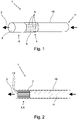
- the smoking article 1 in the form of a cigarette has a cooling device 4 , the cooling device 4 including a cooling material 5 .
- the cooling device 4 is arranged in front of a filter element 6 in the flow direction of the particle-laden gas 3 (represented by the arrows).
- a carrier material 7 is arranged inside the cooling device 4 (cf. 3 ), on which particles 8 of the cooling material 5 are scattered in the interstices of the folded carrier material 7 .
- the cooling device 4 is designed as a separate segment 9 in the cylindrical arrangement of the cigarette.
- the filter element 6 with the mouthpiece 2 adjoins one end of the cooling device 4.
- the tobacco smoke or generally the particle-laden gas 3 flows through the smoking article 1 and accordingly through the cooling device 4 in which the cooling material 5 is arranged.
- the high temperature of the particle-laden gas 3 is sufficient to activate an endothermic process in the cooling material 5 . In this endothermic process, energy is required, which is extracted from the gas 3 laden with particles. The extracted energy results in a decrease in temperature of the particle-laden gas 3, which then flows further into the filter element 6 and exits the mouthpiece 2 at a temperature that the user finds comfortable.
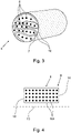
- the cooling device 5 is of a multiple folded carrier material 7 formed.
- the folds 12 are aligned transversely to the direction of flow of the particle-laden gas 3 .
- the carrier material 7 is designed to be air-permeable so that the user can suck it up without any problems.
- the carrier material 7 is coated with the cooling material 5 .
- the cooling material 5 was previously printed onto the carrier material 7 during production.
- the cooling device 4 simultaneously represents the filter element 6, filter material being interspersed between the folds 12 of the carrier material 7 in order to filter out pollutants in the particle-laden gas 3 formed by the burning tobacco rod 11.
- FIG. 3 shows a cooling device 4 for a smoking article 1 in a sectional view.
- a carrier material 7 is shown which is folded several times.
- the carrier material 7 is coated with the cooling material 5 by prior printing of the carrier material 7 with the cooling material 5 .
- small particles 8 of the cooling material 5 are arranged between the folds 12 of the carrier material 7 in order to maximize the cooling effect of the cooling device 4 .
- the carrier material 7 of the cooling device 4 is not made of an air-permeable material.
- the folds 12 of the carrier material 7 must therefore be aligned in a smoking article 1 in the flow direction of the particle-laden gas 3 so that the particle-laden gas 3 can easily flow through the cooling device 4 when the user sucks it.
- the surface of the carrier material 7 is only flowed against, but not flowed through.
- the cooling device 4 shows a detail of a smoking article 1 in a sectional view with a separate cooling device 4.
- the cooling device 4 has a housing 13 in which the cooling material 5 is arranged in small porous particles 8.
- FIG. The housing 13 serves to enclose the cooling material 5 so that it cannot be distributed in the smoking article 1.
- the housing 13 of the cooling device 4 has a perforated inlet opening 14 for incoming particle-laden gas 3 and a perforated outlet opening 15 .
- the particle-laden gas 3 can flow through the inlet opening 14 and through the outlet opening 15 and thereby comes into contact with the cooling material 5, whereby the cooling of the particle-laden gas 3 is activated due to the high temperature of the particle-laden gas.
- the cooling device 4 as a separate segment 9 can be removed from the smoking article 1 and used if necessary. In this way, a user can decide for himself when he thinks it makes sense to cool the particle-laden gas 3 emerging from the mouthpiece 2 .
Description
Die Erfindung betrifft einen Rauchartikel mit einem Mundstück zum Ansaugen eines partikelbeladenen Gases, wobei das partikelbeladene Gas erwärmt ist. Daneben betrifft die Erfindung noch ein Verfahren zum Kühlen eines erwärmten partikelbeladenen Gases in einem Rauchartikel.The invention relates to a smoking article with a mouthpiece for sucking in a particle-laden gas, the particle-laden gas being heated. In addition, the invention also relates to a method for cooling a heated particle-laden gas in a smoking article.
Ein Rauchartikel, typischerweise eine Zigarette, umfasst zumindest eine Tabaksäule, die von einem Umhüllungsmaterial umhüllt wird. In vielen Fällen sind Rauchartikel auch mit Filtern ausgestattet, um die Art und Menge der Substanzen im Rauch zu beeinflussen. Solche Filter, meist aus Zelluloseacetat oder Papier, können den partikulären Anteil des Rauchs vermindern. Filter können auch andere Stoffe, wie Aktivkohle oder Aromastoffe enthalten.A smoking article, typically a cigarette, includes at least one column of tobacco wrapped by a wrapping material. In many cases, smoking articles are also equipped with filters to affect the type and amount of substances in the smoke. Such filters, mostly made of cellulose acetate or paper, can reduce the particulate content of the smoke. Filters can also contain other substances such as activated carbon or flavorings.
Es ist allgemein bekannt, dass bei der Verbrennung von Tabak in Rauchartikeln viele gesundheitsschädliche Substanzen entstehen. Es besteht daher ein Interesse der Industrie, Rauchartikel zu produzieren, deren Rauch nennenswert weniger schädliche Substanzen enthält.It is well known that the combustion of tobacco in smoking articles produces many harmful substances. There is therefore an interest in the industry to produce smoking articles whose smoke contains significantly fewer harmful substances.
Mittlerweile sind im Stand der Technik auch elektronische Zigaretten, oder kurz E-Zigaretten, aber auch elektronische Verdampfungsgeräte weit verbreitet. Diese sind in unterschiedlichen Ausführungsformen im Stand der Technik bekannt und werden als Ersatz für herkömmliche Tabak-Zigaretten, die abgebrannt werden, verwendet. Sie sind gegenüber den Tabak-Zigaretten gesundheitlich vorteilhafter, da aufgrund des für die Verdampfung vorgesehenen Liquids keine Verbrennung stattfindet, bei der ansonsten eine größere Anzahl an Schadstoffen freigesetzt wird, wodurch sie somit als weniger gesundheitsschädlich anzusehen sind.In the meantime, electronic cigarettes, or e-cigarettes for short, but also electronic vaporization devices are also widespread in the prior art. These are known in various embodiments in the prior art and are used as a substitute for conventional tobacco cigarettes that are burned off. Compared to tobacco cigarettes, they are healthier because the liquid intended for vaporization means that there is no combustion, which would otherwise release a larger number of pollutants, which means that they are considered to be less harmful to health.
Bei den bekannten elektronischen Zigaretten werden eine in einem Tank enthaltene Flüssigkeit oder Liquid einem Verdampfer zugeführt, in dem sie verdampft werden. Der Dampf wird dann über einen Strömungskanal zu einer Auslassöffnung in ein Mundstück geleitet und kann von dem Anwender eingeatmet werden. Um das Liquid zu dem Verdampfer zu befördern, werden in der Regel Trägermaterialien verwendet. Diese können beispielsweise aus Glasfasern, watteartig gebildetem Baumwollmaterial, Edelstahlsieben oder Ähnlichem gebildet sein.In the case of the known electronic cigarettes, a liquid or liquid contained in a tank is supplied to an evaporator in which it is vaporized. The vapor is then directed via a flow channel to an outlet opening in a mouthpiece and can be inhaled by the user. Carrier materials are usually used to transport the liquid to the vaporizer. These can be formed, for example, from glass fibers, cotton material formed like cotton wool, stainless steel screens or the like.
Daneben erfreuen sich sogenannte "Heat not Burn Produkte" immer größerer Beliebtheit. Dabei wird der Tabak nicht, wie bei einer herkömmlichen Zigarette, verbrannt, sondern lediglich mit einem elektronischen Zusatzgerät aufgeheizt. Dadurch wird die Bildung von gesundheitsschädlichen Stoffen verhindert, die beim thermischen Zerfall des Tabaks entstehen würden, wenn dieser verbrannt wird.In addition, so-called "heat not burn products" are becoming increasingly popular. Unlike a conventional cigarette, the tobacco is not burned, but only heated up with an additional electronic device. This prevents the formation of harmful substances that would be produced by thermal decomposition of the tobacco when it is burned.
Alle vorgenannten Produkte, sowie herkömmliche Rauchartikel, weisen allgemein den Nachteil auf, dass der eingeatmete Dampf oder Rauch beim Anwender mit einer hohen Temperatur aufgenommen wird. Dies ist für den Anwender mitunter unangenehm.All of the aforementioned products, as well as conventional smoking articles, generally have the disadvantage that the vapor or smoke inhaled by the user is absorbed at a high temperature. This is sometimes uncomfortable for the user.
Die
Der vorliegenden Erfindung liegt daher die Aufgabe zugrunde, einen Rauchartikel sowie ein Verfahren zum Kühlen eines erwärmten partikelbeladenen Gases anzugeben, bei denen die Temperatur des vom Anwender von einem Rauchartikel aufgenommenen Gases, Aerosols oder Dampfes reduziert werden kann.The present invention is therefore based on the object of specifying a smoking article and a method for cooling a heated particle-laden gas, in which the temperature of the gas, aerosol or vapor taken up by the user of a smoking article can be reduced.
Diese Aufgabe ist bei dem eingangs genannten Rauchartikel gemäß dem Patentanspruch 1 dadurch gelöst, dass mindestens eine Kühleinrichtung zum Kühlen des partikelbeladenen Gases umfasst ist, dass das partikelbeladene Gas beim Ansaugen durch die Kühleinrichtung strömt, dass die Kühleinrichtung ein Kühlmaterial aufweist, dass das Kühlen durch die Kühleinrichtung mittels eines endothermen Prozesses des Kühlmaterials realisiert ist und dass der endotherme Prozess durch das erwärmte partikelbeladene Gas aktiviert ist. Erfindungsgemäß weist die Kühleinrichtung ein längliches Trägermaterial auf, das das Kühlmaterial umfasst, wobei das Kühlmaterial auf der Oberfläche des Trägermaterials aufgebracht ist. Es bietet sich an, dass das Kühlmaterial aufgedruckt oder aufgestrichen ist. Somit ist ein möglichst großflächiger Auftrag des Kühlmaterials möglich, wodurch das partikelbeladene Gas besser abgekühlt werden kann. Das Trägermaterial kann auch gleichzeitig die Kühleinrichtung bilden.This object is achieved with the smoking article mentioned at the outset according to
Die zuvor genannte Aufgabe ist bei einer alternativen Ausgestalung der Erfindung gemäß dem Patentanspruch 3 dadurch gelöst, dass die Kühleinrichtung ein längliches Trägermaterial aufweist, das das Kühlmaterial umfasst, wobei das Trägermaterial mehrfach gefaltet ist. Auf diese Weise ist eine möglichst große Oberfläche geschaffen, an der das partikelbeladene Gas vorbei- oder durch die das partikelbeladene Gas hindurchströmt.The aforementioned object is achieved in an alternative embodiment of the invention according to
Das Trägermaterial kann aus einem dünnen Material bestehen, damit möglichst viele Faltungen und eine entsprechend große Oberfläche realisiert werden können, ohne die Dimensionen des Rauchartikels unverhältnismäßig zu vergrößern. Die Faltungen können auch derart ausgestaltet sein, dass das Trägermaterial gerollt oder geschnitten und in Teilen übereinander gelegt ist. Das Kühlmaterial kann zuvor auf das Trägermaterial aufgedruckt oder aufgestrichen werden. Auf diese Weise ist ein möglichst großflächiger Auftrag des Kühlmaterials möglich, wodurch das partikelbeladene Gas besser abgekühlt werden kann.The carrier material can consist of a thin material so that as many folds as possible and a correspondingly large surface can be realized without disproportionately increasing the dimensions of the smoking article. The folds can also be designed in such a way that the carrier material is rolled or cut and placed one on top of the other in parts. The cooling material can be printed or painted on the carrier material beforehand. In this way, the cooling material can be applied over as large an area as possible, as a result of which the particle-laden gas can be cooled better.
Unter einem partikelbeladenen Gas sind Gase allgemein zu verstehen, die einen weiteren Bestandteil enthalten, vor allem auch Aerosole mit festen und/oder flüssigen Bestandteilen sowie Dampf, Nebel und Rauch. Beim Konsum eines Rauchartikels saugt der Anwender in der Regel Luft durch ein Mundstück an. Die Luft strömt durch den Rauchartikel. Bei einer herkömmlichen Zigarette wird zusätzlich Tabakrauch angesaugt, der zunächst durch den Tabakstrang und möglicherweise durch einen Filter strömt, bevor er aus dem Mundstück austritt und vom Anwender inhaliert werden kann.A particle-laden gas is generally understood to mean gases that contain another component, especially aerosols with solid and/or liquid components, as well as vapour, mist and smoke. When consuming a smoking article, the user typically sucks in air through a mouthpiece. The air flows through the smoking article. In a conventional cigarette, tobacco smoke is also sucked in, which first flows through the tobacco rod and possibly through a filter before it exits the mouthpiece and can be inhaled by the user.
Bei der vorliegenden Erfindung ist zusätzlich eine Kühleinrichtung vorgesehen, durch die die angesaugte Luft und beispielsweise Tabakrauch strömen muss, bevor der Gasstrom, also das Gemisch aus der angesaugten Luft und dem Tabakrauch, oder Nassdampf einer E-Zigarette, im Folgenden allgemein partikelbeladenes Gas genannt, aus dem Mundstück austreten kann. Die Kühleinrichtung umfasst ein Kühlmaterial, an dem das partikelbeladene Gas vorbeiströmen und/oder hindurchströmen kann. Das partikelbeladene Gas ist aufgrund einer Verdampfung oder eines Verbrennungsprozesses aufgeheizt. Diese Wärmemenge dient dazu, um bei dem Kühlmaterial einen endothermen Prozess zu aktivieren. Bei einem endothermen Prozess muss von außen Energie zugeführt werden, damit der Vorgang gestartet wird und ablaufen kann. Diese Energie wird von dem aufgeheizten bzw. erwärmten partikelbeladenen Gas geliefert. Beim Verlassen der Kühleinrichtung hat das partikelbeladene Gas infolgedessen eine geringere Enthalpie als vor Eintritt in die Kühleinrichtung. Eine geringere Enthalpie ist gleichbedeutend mit einer geringeren Temperatur. Das partikelbeladene Gas tritt folglich mit einer deutlich geringeren Temperatur aus dem Mundstück aus, als es gehabt hätte, wenn der endotherme Prozess des Kühlmaterials in der Kühleinrichtung nicht aktiviert worden wäre.In the present invention, a cooling device is additionally provided, through which the sucked air and, for example, tobacco smoke must flow before the gas flow, i.e. the mixture of the sucked air and the tobacco smoke, or wet vapor of an e-cigarette, hereinafter generally referred to as particle-laden gas, can escape from the mouthpiece. The cooling device comprises a cooling material which the particle-laden gas can flow past and/or through. The particle-laden gas is heated due to an evaporation or a combustion process. This amount of heat serves to activate an endothermic process in the cooling material. In an endothermic process, energy must be supplied from the outside so that the process can start and run. This energy is supplied by the heated or heated particle-laden gas. As a result, when leaving the cooling device, the particle-laden gas has a lower enthalpy than before entering it cooling device. Lower enthalpy means lower temperature. The particle-laden gas consequently exits the nozzle at a significantly lower temperature than it would have had if the endothermic process of the cooling material in the cooling device had not been activated.
Die Art und Weise des Ablaufs des endothermen Prozesses richtet sich nach der Art und Beschaffenheit des Kühlmaterials. Bei einer vorteilhaften Ausgestaltung der Erfindung ist daher vorgesehen, dass der endotherme Prozess mittels Desorption realisiert ist. Dabei hat es sich als vorteilhaft erwiesen, Stoffe als Kühlmaterial zu verwenden, die absorbiertes Wasser an die Umgebung abgeben können. Als Kühlmittel können daher insbesondere Kieselgel und/oder Zeolith verwendet werden.The manner in which the endothermic process occurs depends on the type and nature of the cooling material. In an advantageous embodiment of the invention, it is therefore provided that the endothermic process is implemented by means of desorption. It has proven to be advantageous to use substances as cooling material that can release absorbed water to the environment. In particular, silica gel and/or zeolite can therefore be used as coolants.
Bei einer weiteren Ausgestaltung der Erfindung ist vorgesehen, dass der endotherme Prozess mittels Schmelzen und/oder Verdampfen des Kühlmaterials realisiert ist. Auch beim Schmelzen bzw. Verdampfen wird Energie in das Kühlmaterial eingebracht. Die benötigte Schmelz- bzw. Verdampfungsenthalpie, also die Energiemenge, die benötigt wird, um eine Stoffprobe an ihrem Schmelzpunkt bei konstantem Druck zu schmelzen bzw. an ihrem Siedepunkt zu verdampfen, also vom festen in den flüssigen oder vom flüssigen in den gasförmigen Aggregatzustand zu überführen, die von außen eingebracht wird, sorgt dafür, dass sich das partikelbeladene Gas abkühlt, bevor es aus dem Mundstück austritt. Als Kühlmaterial eignen sich sowohl anorganische als auch organische Substanzen.In a further embodiment of the invention, it is provided that the endothermic process is realized by melting and/or evaporating the cooling material. Energy is also introduced into the cooling material when it melts or evaporates. The required melting or vaporization enthalpy, i.e. the amount of energy required to melt a substance sample at its melting point at constant pressure or to vaporize it at its boiling point, i.e. to convert it from a solid to a liquid or from a liquid to a gaseous state of aggregation , which is introduced from the outside, ensures that the particle-laden gas cools down before it exits the mouthpiece. Both inorganic and organic substances are suitable as cooling material.
Eine weitere zusätzliche oder alternative Möglichkeit, den endothermen Prozess auszugestalten, sieht vor, dass der endotherme Prozess mittels Freisetzen von Kristallwasser eines anorganischen Salzes realisiert ist. Als Kühlmittel können daher insbesondere Glaubersalz, also Natriumsulfat-Hydrat, und Bittersalz, also Magnesiumsulfat-Hydrat, verwendet werden. Natriumsulfat wird in der Tabakindustrie teilweise zur Glimmhemmung von Umhüllungsmaterial verwendet, damit das Umhüllungsmaterial nicht zu schnell abbrennt. Diese und entsprechend ähnliche anorganischen Salze liegen unter Normalbedingungen als kristalliner Festkörper vor. Das Kristallwasser bzw. Hydratwasser ist durch die kristalline Gitterstruktur innerhalb des Festkörpers gebunden. Im Gegensatz zur Desorption, bei denen die Wassermoleküle nicht am Kristallgitter beteiligt sind, werden die Wassermoleküle bei diesen Salzen koordinativ an Ionen oder über Wasserstoffbrückenbindungen gebunden. Für das Freisetzen des Kristallwassers wird Energie benötigt. Die Energie wird durch das erwärmte partikelbeladene Gas zur Verfügung gestellt. Bei diesem Vorgang kühlt sich das partikelbeladene Gas folglich ab, bevor es aus dem Mundstück austreten kann.A further additional or alternative possibility of designing the endothermic process provides that the endothermic process is realized by releasing water of crystallization of an inorganic salt. Therefore, in particular, Glauber's salt, ie sodium sulphate hydrate, and Epsom salt, ie magnesium sulphate hydrate, can be used as coolants. Sodium sulphate is sometimes used in the tobacco industry to inhibit the smoldering of wrapping material so that the wrapping material does not burn off too quickly. These and correspondingly similar inorganic salts exist as crystalline solids under standard conditions. The crystal water or water of hydration is bound by the crystalline lattice structure within the solid. In contrast to desorption, in which the water molecules do not participate in the crystal lattice, in these salts the water molecules become coordinative bound to ions or via hydrogen bonds. Energy is required to release the crystal water. The energy is provided by the heated, particle-laden gas. During this process, the particle-laden gas cools down before it can exit the mouthpiece.
Die Kühleinrichtung kann an verschiedenen Stellen des Rauchartikels angeordnet sein. Bei einer Ausgestaltung der Erfindung ist vorgesehen, dass ein Filterelement umfasst ist, dass das Filterelement in Strömungsrichtung des partikelbeladenen Gases vor dem Mundstück angeordnet ist und dass das Filterelement die Kühleinrichtung umfasst. Durch die Anordnung der Kühleinrichtung im Filterelement kann der Rauchartikel, wenn es sich beispielsweise um eine herkömmliche Zigarette handelt, beinahe ohne Änderung ausgestaltet werden. Eine Zigarette mit einem Filterelement weist bereits Strukturen auf, in denen die Kühleinrichtung mit dem Kühlmaterial eingebracht werden kann.The cooling device can be arranged at different points of the smoking article. In one embodiment of the invention, it is provided that a filter element is included, that the filter element is arranged in front of the mouthpiece in the direction of flow of the particle-laden gas, and that the filter element includes the cooling device. By arranging the cooling device in the filter element, the smoking article, for example if it is a conventional cigarette, can be designed almost without any changes. A cigarette with a filter element already has structures in which the cooling device can be introduced with the cooling material.
Das Trägermaterial kann derart in den Rauchartikel eingebracht werden, dass die Faltungen quer zur Strömungsrichtung des partikelbeladenen Gases angeordnet sind. Auf diese Weise muss das partikelbeladene Gas durch das Trägermaterial hindurchströmen. Für diese Ausgestaltung empfiehlt es sich, ein Trägermaterial auszuwählen, das keinen zu großen Druckverlust beim Ansaugen des Anwenders am Mundstück verursacht, damit das Ansaugen vom Anwender nicht als anstrengend oder unangenehm aufgefasst wird. Das Trägermaterial muss daher luftdurchlässig sein.The carrier material can be introduced into the smoking article in such a way that the folds are arranged transversely to the direction of flow of the particle-laden gas. In this way, the particle-laden gas must flow through the carrier material. For this configuration, it is advisable to select a carrier material that does not cause too great a pressure loss when the user sucks on the mouthpiece, so that the user does not perceive the sucking as strenuous or uncomfortable. The carrier material must therefore be air-permeable.
Das Trägermaterial kann ebenfalls derart in dem Rauchartikel eingebracht sein, dass die Faltungen in Strömungsrichtung des partikelbeladenen Gases angeordnet sind. Auf diese Weise wird das Trägermaterial von dem partikelbeladenen Gas angeströmt, aber nicht durchströmt. Eine Luftdurchlässigkeit des Trägermaterials ist bei dieser Ausgestaltung daher nicht zwingend notwendig.The carrier material can also be introduced into the smoking article in such a way that the folds are arranged in the direction of flow of the particle-laden gas. In this way, the particle-laden gas flows against the carrier material, but does not flow through it. Air permeability of the carrier material is therefore not absolutely necessary in this configuration.
Darüber hinaus kann vorgesehen sein, dass das Trägermaterial gleichzeitig Teil der Kühleinrichtung und des Filterelements ist. Bei Anordnung der Faltungen in oder quer zur Strömungsrichtung des partikelbeladenen Gases kann zusätzlich Filtermaterial zur Filterung des partikelbeladenen Gases in den Zwischenräumen der Faltungen eingebracht sein. Denkbar ist auch, dass das Trägermaterial bereits aus Filtermaterial hergestellt ist. Außerdem können die alternativen Anordnungen der Faltungen des Trägermaterials in dem Rauchartikel auch gleichzeitig realisiert werden. Der Rauchartikel weist dann einen Abschnitt auf, in dem die Faltungen des Trägermaterials in Strömungsrichtung des partikelbeladenen Gases ausgerichtet sind und einen Abschnitt, in dem die Faltungen quer zur Strömungsrichtung des partikelbeladenen Gases ausgerichtet sind.In addition, it can be provided that the carrier material is part of the cooling device and the filter element at the same time. If the folds are arranged in or transversely to the direction of flow of the particle-laden gas, filter material for filtering the particle-laden gas can also be introduced into the spaces between the folds. It is also conceivable that the carrier material is already made of filter material. Besides, they can alternative arrangements of the folds of the carrier material in the smoking article can also be realized at the same time. The smoking article then has a section in which the folds of the carrier material are aligned in the flow direction of the particle-laden gas and a section in which the folds are aligned transversely to the flow direction of the particle-laden gas.
Zusätzlich kann vorgesehen sein, dass das Kühlmaterial in das Trägermaterial eingebracht ist. Das Kühlmaterial kann schon bei der Herstellung des Trägermaterials, das beispielsweise aus Papier hergestellt werden kann, in die Papiermasse mit eingearbeitet werden.In addition, it can be provided that the cooling material is introduced into the carrier material. The cooling material can already be incorporated into the paper pulp during the manufacture of the carrier material, which can be made from paper, for example.
Zusätzlich kann bei einer weiteren Ausgestaltung der Erfindung das Kühlmaterial in kleinen Partikeln in die Kühleinrichtung eingebracht sein. Die kleinen Partikel können beispielsweise zusätzlich zu der zuvor beschriebenen Ausgestaltung in die Zwischenräume der Faltungen des Trägermaterials eingebracht werden, um den Effekt der Kühleinrichtung weiter zu verbessern. Weist der Rauchartikel einen herkömmlichen Filter auf, der auch die Kühleinrichtung umfasst, kann das Kühlmaterial auch in das Filtermaterial eingestreut werden. Das Filterelement übernimmt dann eine Doppelfunktion, da es toxische Stoffe aus dem partikelbeladenen Gas filtert und gleichzeitig für die Kühlung des partikelbeladenen Gases sorgt. Zusätzlich oder alternativ kann die Kühleinrichtung bei einem Rauchartikel mit Tabakmischung auch direkt in der Tabakmischung vorgesehen sein, wobei die kleinen Partikel dann in die Tabakmischung eingebracht werden. Die Größe der Partikel hängt auch von der Beschaffenheit des Kühlmaterials ab. Denkbar sind generell alle Korngrößenverteilungen, die die Dimensionen des Rauchartikels nicht unverhältnismäßig vergrößern. Unverhältnismäßig bedeutet in diesem Zusammenhang eine starke Abweichung zu den Dimensionen eines herkömmlichen Rauchartikels.In addition, in a further embodiment of the invention, the cooling material can be introduced into the cooling device in small particles. In addition to the configuration described above, the small particles can, for example, be introduced into the spaces between the folds of the carrier material in order to further improve the effect of the cooling device. If the smoking article has a conventional filter which also includes the cooling device, the cooling material can also be sprinkled into the filter material. The filter element then takes on a dual function, since it filters toxic substances from the particle-laden gas and at the same time ensures the cooling of the particle-laden gas. In addition or as an alternative, the cooling device can also be provided directly in the tobacco mixture in a smoking article with a tobacco mixture, with the small particles then being introduced into the tobacco mixture. The size of the particles also depends on the nature of the cooling material. In general, all particle size distributions that do not disproportionately increase the dimensions of the smoking article are conceivable. Disproportionate in this context means a strong deviation from the dimensions of a conventional smoking article.
Eine weitere Ausgestaltung des erfindungsgemäßen Rauchartikels sieht vor, dass die Kühleinrichtung als separates Segment in Strömungsrichtung des partikelbeladenen Gases vor dem Mundstück angeordnet ist. Das separate Segment kann eine Vielzahl an Formen aufweisen. Beispielhaft sei eine bevorzugte Zylinderform beschrieben, auf die die Erfindung nicht begrenzt sein soll. Herkömmliche Rauchartikel sind meist im wesentlichen zylinderförmig ausgestaltet. Das separate Segment kann dabei außerdem in Strömungsrichtung des partikelbeladenen Gases vor einem möglichen Filter angeordnet sein. Die Kühleinrichtung als separates Segment kann beispielsweise vollständig aus dem Kühlmaterial bestehen. Denkbar ist auch, dass das separate Segment eine Art Gehäuse aufweist, so dass das Kühlmaterial gekapselt als poröses Material oder als Pulver in dem Gehäuse vorliegen kann. Das Gehäuse weist eine Eintrittsöffnung und eine Austrittsöffnung für das partikelbeladene Gas auf, durch die es aufgrund des Ansaugens durch das Mundstück vom Anwender hindurchströmt. Die Kühleinrichtung kann auch optional in bzw. an dem Rauchartikel anbringbar sein. Auf diese Weise hat ein Anwender die Option, das partikelbeladene Gas nur zu kühlen, wenn er es für notwendig hält.A further embodiment of the smoking article according to the invention provides that the cooling device is arranged as a separate segment in the direction of flow of the particle-laden gas in front of the mouthpiece. The separate segment can have a variety of shapes. A preferred cylindrical shape is described as an example, to which the invention should not be limited. Conventional smoking articles are mostly configured essentially in the form of a cylinder. The separate segment can also be in the direction of flow of the particle-laden gas can be arranged in front of a possible filter. The cooling device as a separate segment can, for example, consist entirely of the cooling material. It is also conceivable that the separate segment has a type of housing, so that the cooling material can be encapsulated as a porous material or as a powder in the housing. The housing has an inlet opening and an outlet opening for the particle-laden gas, through which it flows as a result of being sucked in through the user's mouthpiece. The cooling device can also optionally be attachable in or on the smoking article. In this way, a user has the option of only cooling the particle-laden gas if they deem it necessary.
Die zuvor genannte Aufgabe ist bei einem eingangs beschriebenen Verfahren zum Kühlen eines erwärmten partikelbeladenen Gases in einem Rauchartikel mit den Merkmalen des Patentanspruchs 10 dadurch gelöst, dass das partikelbeladene Gas bei Ansaugen durch eine Kühleinrichtung geleitet wird, dass die Kühleinrichtung ein Kühlmaterial aufweist, dass das Kühlen durch die Kühleinrichtung mittels eines endothermen Prozesses des Kühlmaterials realisiert wird und dass der endotherme Prozess durch das erwärmte partikelbeladene Gas aktiviert wird.The aforementioned object is achieved in a method for cooling a heated particle-laden gas in a smoking article with the features of
Bei dem erfindungsgemäßen Verfahren ist das Kühlmaterial derart wählbar, dass verschiedene endotherme Prozesse in Gang gesetzt werden können. Zum einen ist vorgesehen, dass der endotherme Prozess mittels Desorption realisiert wird. Eine weitere Möglichkeit besteht darin, dass der endotherme Prozess mittels Schmelzen des Kühlmaterials realisiert wird. Außerdem ist es möglich, dass der endotherme Prozess mittels Freisetzen von Kristallwasser eines anorganischen Salzes realisiert wird.In the method according to the invention, the cooling material can be selected in such a way that various endothermic processes can be started. On the one hand, it is planned that the endothermic process will be realized by means of desorption. Another possibility is that the endothermic process is realized by melting the cooling material. In addition, it is possible that the endothermic process is realized by releasing crystal water of an inorganic salt.
Im Einzelnen gibt es mehrere Möglichkeiten, den erfindungsgemäßen Rauchartikel und das erfindungsgemäße Verfahren auszugestalten und weiterzubilden. Dazu wird verwiesen sowohl auf die den Patentansprüchen 1, 3 und 10 nachgeordneten Patentansprüche, als auch auf die nachfolgende Beschreibung bevorzugter Ausführungsbeispiele in Verbindung mit der Zeichnung. In der Zeichnung zeigen
- Fig. 1
- eine schematische Darstellung eines Ausführungsbeispiels eines Rauchartikels mit einer Kühleinrichtung,
- Fig. 2
- eine schematische Schnittdarstellung eines Rauchartikels mit einer Kühleinrichtung,
- Fig. 3
- eine schematische Darstellung einer Kühleinrichtung für einen Rauchartikel und
- Fig. 4
- eine schematische Schnittdarstellung einer gekapselten Kühleinrichtung in einem Rauchartikel.
- 1
- a schematic representation of an embodiment of a smoking article with a cooling device,
- 2
- a schematic sectional view of a smoking article with a cooling device,
- 3
- a schematic representation of a cooling device for a smoking article and
- 4
- a schematic sectional view of an encapsulated cooling device in a smoking article.
- 11
- Rauchartikelsmoking articles
- 22
- Mundstückmouthpiece
- 33
- partikelbeladenes Gasparticle laden gas
- 44
- Kühleinrichtungcooling device
- 55
- Kühlmaterialcooling material
- 66
- Filterelementfilter element
- 77
- Trägermaterialcarrier material
- 88th
- Partikelparticles
- 99
- Segmentsegment
- 1010
- Umhüllungsmaterialwrapping material
- 1111
- Tabakstrangtobacco rod
- 1212
- Faltungenfolds
- 1313
- GehäuseHousing
- 1414
- Eintrittsöffnungentry opening
- 1515
- Austrittsöffnungexit port
Claims (13)
- Smoking article (1), having a mouthpiece (2) for drawing in a particle-loaded gas (3), wherein the particle-loaded gas (3) is heated,wherein at least one cooling element (4) is included for cooling the particle-loaded gas (3), that the particle-loaded gas (3) flows through the cooling element (4) during the drawing-in action, that the cooling element (4) has a cooling material (5), that the cooling by the cooling element (4) is implemented by means of an endothermic process of the cooling material (5) and that the endothermic process is activated by the heated particle-loaded gas (3),characterized inthat the cooling element (4) has an elongate carrier material (7), that the elongate carrier material (7) comprises the cooling material (5) and that the cooling material (5) is applied to the surface of the carrier material (7).
- Smoking article (1) according to claim 1, characterized in that the carrier material (7) is folded several times.
- Smoking article (1), having a mouthpiece (2) for drawing in a particle-loaded gas (3), wherein the particle-loaded gas (3) is heated,wherein at least one cooling element (4) is included for cooling the particle-loaded gas (3), that the particle-loaded gas (3) flows through the cooling element (4) during the drawing-in action, that the cooling element (4) has a cooling material (5), that the cooling by the cooling element (4) is implemented by means of an endothermic process of the cooling material (5) and that the endothermic process is activated by the heated particle-loaded gas (3),characterized inthat the cooling element (4) has an elongate carrier material (7), that the elongate carrier material (7) comprises the cooling material (5) and that the carrier material (7) is folded several times.
- Smoking article (1) according to any one of claims 1 to 3, characterized in that the endothermic process is implemented by means of desorption.
- Smoking article (1) according to any one of claims 1 to 4, characterized in that the endothermic process is implemented by melting and/or vaporizing the cooling material (5).
- Smoking article (1) according to claim 1 to 5, characterized in that the endothermic process is implemented by releasing water of crystallization of an inorganic salt.
- Smoking article (1) according to any one of claims 1 to 6, characterized in that a filter element (6) is included, that the filter element (6) is arranged in front of the mouthpiece (2) in the flow direction of the particle-loaded gas (3) and that the filter element (6) includes the cooling element (4).
- Smoking article (1) according to any one of claims 1 to 7, characterized in that the cooling material (5) is incorporated in the carrier material (7).
- Smoking article (1) according to any one of claims 1 to 8, characterized in that the cooling element (4) is arranged as a separate segment (9) in front of the mouthpiece (2) in the direction of flow of the particle-loaded gas (3).
- Method for cooling a heated particle-loaded gas (3) in a smoking article according to any one of claims 1 to 9,
characterized in
that the particle-loaded gas (3) is guided through a cooling element (4) during the drawing-in action, that the cooling element (4) has a cooling material (5), that the cooling by the cooling element (4) is implemented by means of an endothermic process of the cooling material (5), and that the endothermic process is activated by the heated particle-loaded gas (4). - Method according to claim 10, characterized in that the endothermic process is implemented by means of desorption.
- Method according to claim 10 or 11, characterized in that the endothermic process is implemented by melting the cooling material (5).
- Method according to any one of claims 10 to 12, characterized in that the endothermic process is implemented by releasing water of crystallization of an inorganic salt.
Applications Claiming Priority (2)
| Application Number | Priority Date | Filing Date | Title |
|---|---|---|---|
| DE102017120202.1A DE102017120202B4 (en) | 2017-09-01 | 2017-09-01 | Smoking article and method for cooling a heated particulate-laden gas |
| PCT/EP2018/072033 WO2019042762A1 (en) | 2017-09-01 | 2018-08-14 | Smoking article and method for cooling a heated particle-loaded gas |
Publications (2)
| Publication Number | Publication Date |
|---|---|
| EP3675659A1 EP3675659A1 (en) | 2020-07-08 |
| EP3675659B1 true EP3675659B1 (en) | 2023-01-25 |
Family
ID=63407183
Family Applications (1)
| Application Number | Title | Priority Date | Filing Date |
|---|---|---|---|
| EP18762025.7A Active EP3675659B1 (en) | 2017-09-01 | 2018-08-14 | Smoking article and method for cooling a heated particle-loaded gas |
Country Status (10)
| Country | Link |
|---|---|
| US (1) | US20200329757A1 (en) |
| EP (1) | EP3675659B1 (en) |
| JP (1) | JP2020531052A (en) |
| KR (1) | KR20200044933A (en) |
| CN (1) | CN111601519A (en) |
| DE (1) | DE102017120202B4 (en) |
| ES (1) | ES2943087T3 (en) |
| LT (1) | LT3675659T (en) |
| PL (1) | PL3675659T3 (en) |
| WO (1) | WO2019042762A1 (en) |
Families Citing this family (5)
| Publication number | Priority date | Publication date | Assignee | Title |
|---|---|---|---|---|
| CN110063528B (en) * | 2019-05-27 | 2020-09-04 | 江南大学 | Cigarette heater |
| CN112401298A (en) * | 2019-08-27 | 2021-02-26 | 湖北中烟工业有限责任公司 | Cooling filter rod and low-temperature cigarette with same |
| WO2022215174A1 (en) * | 2021-04-06 | 2022-10-13 | 日本たばこ産業株式会社 | Coolant for heat-not-burn tobacco, heat-not-burn tobacco, and electrically heated tobacco product |
| WO2022215177A1 (en) * | 2021-04-06 | 2022-10-13 | 日本たばこ産業株式会社 | Porous material for non-combustion-heating tobacco, non-combustion-heating tobacco, and electric heating tobacco product |
| KR20230104394A (en) * | 2021-12-31 | 2023-07-10 | 주식회사 케이티앤지 | Cooling filter and smoking article comprising same |
Family Cites Families (17)
| Publication number | Priority date | Publication date | Assignee | Title |
|---|---|---|---|---|
| US3513859A (en) * | 1967-11-06 | 1970-05-26 | H2O Filter Corp The | Filter for smoking devices |
| US3547130A (en) * | 1968-02-12 | 1970-12-15 | American Tobacco Co | Method of cooling cigarette smoke |
| US3625228A (en) * | 1969-10-16 | 1971-12-07 | H 2 O Filter Corp The | Heat activated filter for smoking devices |
| US3669128A (en) * | 1970-11-09 | 1972-06-13 | Joseph H Cohen | Device for filtering tobacco smoke |
| GB8329501D0 (en) * | 1983-11-04 | 1983-12-07 | British American Tobacco Co | Smoking articles |
| JP4166365B2 (en) * | 1999-04-09 | 2008-10-15 | 秀希 青木 | Cigarettes and cigarettes |
| DE102004043222A1 (en) * | 2004-09-03 | 2006-03-23 | Fachhochschule Jena | Cigarette, has fire protection filter with filter mouthpiece and tobacco strand, and fire protection layer provided between mouthpiece and strand, where layer consists of crystal aqueous salt such as calcium sulphate dihydrate |
| GB0915814D0 (en) * | 2009-09-10 | 2009-10-07 | British American Tobacco Co | Smoke filtration |
| GB201114675D0 (en) * | 2011-08-25 | 2011-10-12 | British American Tobacco Co | Smoking article filter |
| EP2625975A1 (en) * | 2012-02-13 | 2013-08-14 | Philip Morris Products S.A. | Aerosol-generating article having an aerosol-cooling element |
| EP2625974A1 (en) * | 2012-02-13 | 2013-08-14 | Philip Morris Products S.A. | Aerosol-generating article having a flavour-generating component |
| SG11201406966TA (en) * | 2012-04-30 | 2014-11-27 | Philip Morris Products Sa | Smoking article mouthpiece with cooling agent inclusion complex |
| GB201318055D0 (en) * | 2013-10-11 | 2013-11-27 | British American Tobacco Co | Additive Releasing Materials |
| CN104449586B (en) * | 2014-11-06 | 2017-06-06 | 湖南中烟工业有限责任公司 | A kind of organic/inorganic composite phase-change material of controllable cigarette filter flue-gas temperature and its preparation method and application |
| CN104720101B (en) * | 2015-01-29 | 2017-10-10 | 湖南中烟工业有限责任公司 | A kind of cigarette filter and cigarette |
| CN104720112B (en) * | 2015-01-29 | 2017-09-29 | 湖南中烟工业有限责任公司 | A kind of external cigarette holder for being used to heat the tobacco product that do not burn |
| CN107087811B (en) * | 2017-05-26 | 2019-10-11 | 湖北中烟工业有限责任公司 | With the low temperature cigarette for reducing flue-gas temperature and preventing mouth stick heat from collapsing |
-
2017
- 2017-09-01 DE DE102017120202.1A patent/DE102017120202B4/en active Active
-
2018
- 2018-08-08 US US16/643,017 patent/US20200329757A1/en active Pending
- 2018-08-14 CN CN201880070796.4A patent/CN111601519A/en active Pending
- 2018-08-14 EP EP18762025.7A patent/EP3675659B1/en active Active
- 2018-08-14 JP JP2020533351A patent/JP2020531052A/en active Pending
- 2018-08-14 KR KR1020207009243A patent/KR20200044933A/en not_active Application Discontinuation
- 2018-08-14 ES ES18762025T patent/ES2943087T3/en active Active
- 2018-08-14 WO PCT/EP2018/072033 patent/WO2019042762A1/en unknown
- 2018-08-14 LT LTEPPCT/EP2018/072033T patent/LT3675659T/en unknown
- 2018-08-14 PL PL18762025.7T patent/PL3675659T3/en unknown
Also Published As
| Publication number | Publication date |
|---|---|
| DE102017120202B4 (en) | 2022-08-11 |
| LT3675659T (en) | 2023-07-25 |
| WO2019042762A1 (en) | 2019-03-07 |
| ES2943087T3 (en) | 2023-06-08 |
| CN111601519A (en) | 2020-08-28 |
| EP3675659A1 (en) | 2020-07-08 |
| DE102017120202A1 (en) | 2019-03-07 |
| KR20200044933A (en) | 2020-04-29 |
| JP2020531052A (en) | 2020-11-05 |
| US20200329757A1 (en) | 2020-10-22 |
| PL3675659T3 (en) | 2023-09-04 |
Similar Documents
| Publication | Publication Date | Title |
|---|---|---|
| EP3675659B1 (en) | Smoking article and method for cooling a heated particle-loaded gas | |
| DE102011011676B4 (en) | Smoke-free cigarette, cigar or pipe | |
| EP2456329B1 (en) | Smokeless cigarette substitute | |
| CH679632A5 (en) | ||
| CH679106A5 (en) | ||
| CH712991B1 (en) | Open-pored sintered glasses for use in electronic cigarettes. | |
| DE1517297B1 (en) | Smoke filters for tobacco products | |
| DE102008030548A1 (en) | Smoke-free cigarette | |
| WO2009155958A1 (en) | Smoke-free cigarette | |
| DE3439861A1 (en) | SMOKING ITEMS | |
| CH679631A5 (en) | ||
| EP2277398A1 (en) | Smoke-free cigarette substitute | |
| DE1517312A1 (en) | Filters for smoking articles and cigarettes equipped with them | |
| DE102019135114A1 (en) | FILTER AND / OR FILLING MATERIAL FOR MOUTHPIECES FOR USE WITH SMOKED PRODUCTS OR HNB PRODUCTS, MOUTHPIECES AND CIGARETTE FILTERS WITH SUCH FILTER AND / OR FILLING MATERIAL, AS WELL AS PROCESS FOR PRODUCING SUCH FILTER AND / OR FILTER | |
| DE3715842A1 (en) | SMOKABLE ITEM | |
| DE4001394C2 (en) | Smoking articles | |
| DE1767024C3 (en) | Use of a porous magnesium silicate hydrate as a filter medium for tobacco smoke | |
| WO2009006936A1 (en) | Cigarette filter | |
| EP2269475B1 (en) | Filter for a smoke-free cigarette | |
| EP2269476B1 (en) | Nicotine and aroma matrix | |
| DE1692945C3 (en) | Smoke filter made from sintered plastic particles, especially for cigarettes, and process for its manufacture | |
| DE202022105551U1 (en) | Evaporator with active filter | |
| EP4221522A1 (en) | Assembly for generating aerosol | |
| DE202019100405U1 (en) | Device for avoiding odor nuisance from e-cigarettes | |
| DE202019002370U1 (en) | Substitute for hookah tobacco |
Legal Events
| Date | Code | Title | Description |
|---|---|---|---|
| STAA | Information on the status of an ep patent application or granted ep patent |
Free format text: STATUS: UNKNOWN |
|
| STAA | Information on the status of an ep patent application or granted ep patent |
Free format text: STATUS: THE INTERNATIONAL PUBLICATION HAS BEEN MADE |
|
| PUAI | Public reference made under article 153(3) epc to a published international application that has entered the european phase |
Free format text: ORIGINAL CODE: 0009012 |
|
| STAA | Information on the status of an ep patent application or granted ep patent |
Free format text: STATUS: REQUEST FOR EXAMINATION WAS MADE |
|
| 17P | Request for examination filed |
Effective date: 20200319 |
|
| AK | Designated contracting states |
Kind code of ref document: A1 Designated state(s): AL AT BE BG CH CY CZ DE DK EE ES FI FR GB GR HR HU IE IS IT LI LT LU LV MC MK MT NL NO PL PT RO RS SE SI SK SM TR |
|
| AX | Request for extension of the european patent |
Extension state: BA ME |
|
| DAV | Request for validation of the european patent (deleted) | ||
| DAX | Request for extension of the european patent (deleted) | ||
| REG | Reference to a national code |
Ref country code: DE Ref legal event code: R079 Ref document number: 502018011516 Country of ref document: DE Free format text: PREVIOUS MAIN CLASS: A24D0003000000 Ipc: A24D0003040000 |
|
| GRAP | Despatch of communication of intention to grant a patent |
Free format text: ORIGINAL CODE: EPIDOSNIGR1 |
|
| STAA | Information on the status of an ep patent application or granted ep patent |
Free format text: STATUS: GRANT OF PATENT IS INTENDED |
|
| RIC1 | Information provided on ipc code assigned before grant |
Ipc: A24F 13/04 20060101ALN20220707BHEP Ipc: A24D 3/04 20060101AFI20220707BHEP |
|
| RIC1 | Information provided on ipc code assigned before grant |
Ipc: A24F 13/04 20060101ALN20220725BHEP Ipc: A24D 3/04 20060101AFI20220725BHEP |
|
| INTG | Intention to grant announced |
Effective date: 20220808 |
|
| GRAS | Grant fee paid |
Free format text: ORIGINAL CODE: EPIDOSNIGR3 |
|
| GRAA | (expected) grant |
Free format text: ORIGINAL CODE: 0009210 |
|
| STAA | Information on the status of an ep patent application or granted ep patent |
Free format text: STATUS: THE PATENT HAS BEEN GRANTED |
|
| AK | Designated contracting states |
Kind code of ref document: B1 Designated state(s): AL AT BE BG CH CY CZ DE DK EE ES FI FR GB GR HR HU IE IS IT LI LT LU LV MC MK MT NL NO PL PT RO RS SE SI SK SM TR |
|
| REG | Reference to a national code |
Ref country code: GB Ref legal event code: FG4D Free format text: NOT ENGLISH |
|
| REG | Reference to a national code |
Ref country code: CH Ref legal event code: EP |
|
| REG | Reference to a national code |
Ref country code: DE Ref legal event code: R096 Ref document number: 502018011516 Country of ref document: DE |
|
| REG | Reference to a national code |
Ref country code: AT Ref legal event code: REF Ref document number: 1545375 Country of ref document: AT Kind code of ref document: T Effective date: 20230215 Ref country code: IE Ref legal event code: FG4D Free format text: LANGUAGE OF EP DOCUMENT: GERMAN |
|
| REG | Reference to a national code |
Ref country code: NL Ref legal event code: MP Effective date: 20230125 |
|
| REG | Reference to a national code |
Ref country code: ES Ref legal event code: FG2A Ref document number: 2943087 Country of ref document: ES Kind code of ref document: T3 Effective date: 20230608 |
|
| PG25 | Lapsed in a contracting state [announced via postgrant information from national office to epo] |
Ref country code: NL Free format text: LAPSE BECAUSE OF FAILURE TO SUBMIT A TRANSLATION OF THE DESCRIPTION OR TO PAY THE FEE WITHIN THE PRESCRIBED TIME-LIMIT Effective date: 20230125 |
|
| PG25 | Lapsed in a contracting state [announced via postgrant information from national office to epo] |
Ref country code: RS Free format text: LAPSE BECAUSE OF FAILURE TO SUBMIT A TRANSLATION OF THE DESCRIPTION OR TO PAY THE FEE WITHIN THE PRESCRIBED TIME-LIMIT Effective date: 20230125 Ref country code: PT Free format text: LAPSE BECAUSE OF FAILURE TO SUBMIT A TRANSLATION OF THE DESCRIPTION OR TO PAY THE FEE WITHIN THE PRESCRIBED TIME-LIMIT Effective date: 20230525 Ref country code: NO Free format text: LAPSE BECAUSE OF FAILURE TO SUBMIT A TRANSLATION OF THE DESCRIPTION OR TO PAY THE FEE WITHIN THE PRESCRIBED TIME-LIMIT Effective date: 20230425 Ref country code: LV Free format text: LAPSE BECAUSE OF FAILURE TO SUBMIT A TRANSLATION OF THE DESCRIPTION OR TO PAY THE FEE WITHIN THE PRESCRIBED TIME-LIMIT Effective date: 20230125 Ref country code: HR Free format text: LAPSE BECAUSE OF FAILURE TO SUBMIT A TRANSLATION OF THE DESCRIPTION OR TO PAY THE FEE WITHIN THE PRESCRIBED TIME-LIMIT Effective date: 20230125 |
|
| PG25 | Lapsed in a contracting state [announced via postgrant information from national office to epo] |
Ref country code: SE Free format text: LAPSE BECAUSE OF FAILURE TO SUBMIT A TRANSLATION OF THE DESCRIPTION OR TO PAY THE FEE WITHIN THE PRESCRIBED TIME-LIMIT Effective date: 20230125 Ref country code: IS Free format text: LAPSE BECAUSE OF FAILURE TO SUBMIT A TRANSLATION OF THE DESCRIPTION OR TO PAY THE FEE WITHIN THE PRESCRIBED TIME-LIMIT Effective date: 20230525 Ref country code: GR Free format text: LAPSE BECAUSE OF FAILURE TO SUBMIT A TRANSLATION OF THE DESCRIPTION OR TO PAY THE FEE WITHIN THE PRESCRIBED TIME-LIMIT Effective date: 20230426 Ref country code: FI Free format text: LAPSE BECAUSE OF FAILURE TO SUBMIT A TRANSLATION OF THE DESCRIPTION OR TO PAY THE FEE WITHIN THE PRESCRIBED TIME-LIMIT Effective date: 20230125 |
|
| REG | Reference to a national code |
Ref country code: DE Ref legal event code: R097 Ref document number: 502018011516 Country of ref document: DE |
|
| PG25 | Lapsed in a contracting state [announced via postgrant information from national office to epo] |
Ref country code: SM Free format text: LAPSE BECAUSE OF FAILURE TO SUBMIT A TRANSLATION OF THE DESCRIPTION OR TO PAY THE FEE WITHIN THE PRESCRIBED TIME-LIMIT Effective date: 20230125 Ref country code: EE Free format text: LAPSE BECAUSE OF FAILURE TO SUBMIT A TRANSLATION OF THE DESCRIPTION OR TO PAY THE FEE WITHIN THE PRESCRIBED TIME-LIMIT Effective date: 20230125 Ref country code: DK Free format text: LAPSE BECAUSE OF FAILURE TO SUBMIT A TRANSLATION OF THE DESCRIPTION OR TO PAY THE FEE WITHIN THE PRESCRIBED TIME-LIMIT Effective date: 20230125 Ref country code: CZ Free format text: LAPSE BECAUSE OF FAILURE TO SUBMIT A TRANSLATION OF THE DESCRIPTION OR TO PAY THE FEE WITHIN THE PRESCRIBED TIME-LIMIT Effective date: 20230125 |
|
| PGFP | Annual fee paid to national office [announced via postgrant information from national office to epo] |
Ref country code: TR Payment date: 20230811 Year of fee payment: 6 Ref country code: RO Payment date: 20230803 Year of fee payment: 6 Ref country code: IT Payment date: 20230825 Year of fee payment: 6 Ref country code: GB Payment date: 20230822 Year of fee payment: 6 Ref country code: CH Payment date: 20230902 Year of fee payment: 6 Ref country code: AT Payment date: 20230822 Year of fee payment: 6 |
|
| PG25 | Lapsed in a contracting state [announced via postgrant information from national office to epo] |
Ref country code: SK Free format text: LAPSE BECAUSE OF FAILURE TO SUBMIT A TRANSLATION OF THE DESCRIPTION OR TO PAY THE FEE WITHIN THE PRESCRIBED TIME-LIMIT Effective date: 20230125 |
|
| PGFP | Annual fee paid to national office [announced via postgrant information from national office to epo] |
Ref country code: PL Payment date: 20230804 Year of fee payment: 6 Ref country code: FR Payment date: 20230828 Year of fee payment: 6 |
|
| PLBE | No opposition filed within time limit |
Free format text: ORIGINAL CODE: 0009261 |
|
| STAA | Information on the status of an ep patent application or granted ep patent |
Free format text: STATUS: NO OPPOSITION FILED WITHIN TIME LIMIT |
|
| PGFP | Annual fee paid to national office [announced via postgrant information from national office to epo] |
Ref country code: LT Payment date: 20230721 Year of fee payment: 6 |
|
| 26N | No opposition filed |
Effective date: 20231026 |
|
| PGFP | Annual fee paid to national office [announced via postgrant information from national office to epo] |
Ref country code: ES Payment date: 20231027 Year of fee payment: 6 |
|
| PG25 | Lapsed in a contracting state [announced via postgrant information from national office to epo] |
Ref country code: SI Free format text: LAPSE BECAUSE OF FAILURE TO SUBMIT A TRANSLATION OF THE DESCRIPTION OR TO PAY THE FEE WITHIN THE PRESCRIBED TIME-LIMIT Effective date: 20230125 |
|
| PGFP | Annual fee paid to national office [announced via postgrant information from national office to epo] |
Ref country code: DE Payment date: 20231025 Year of fee payment: 6 |
|
| PG25 | Lapsed in a contracting state [announced via postgrant information from national office to epo] |
Ref country code: MC Free format text: LAPSE BECAUSE OF FAILURE TO SUBMIT A TRANSLATION OF THE DESCRIPTION OR TO PAY THE FEE WITHIN THE PRESCRIBED TIME-LIMIT Effective date: 20230125 |
|
| PG25 | Lapsed in a contracting state [announced via postgrant information from national office to epo] |
Ref country code: MC Free format text: LAPSE BECAUSE OF FAILURE TO SUBMIT A TRANSLATION OF THE DESCRIPTION OR TO PAY THE FEE WITHIN THE PRESCRIBED TIME-LIMIT Effective date: 20230125 |
|
| PG25 | Lapsed in a contracting state [announced via postgrant information from national office to epo] |
Ref country code: LU Free format text: LAPSE BECAUSE OF NON-PAYMENT OF DUE FEES Effective date: 20230814 |