EP3674853A1 - Bildbasiertes informationsverarbeitungsverfahren und -system - Google Patents
Bildbasiertes informationsverarbeitungsverfahren und -system Download PDFInfo
- Publication number
- EP3674853A1 EP3674853A1 EP20156185.9A EP20156185A EP3674853A1 EP 3674853 A1 EP3674853 A1 EP 3674853A1 EP 20156185 A EP20156185 A EP 20156185A EP 3674853 A1 EP3674853 A1 EP 3674853A1
- Authority
- EP
- European Patent Office
- Prior art keywords
- image
- reference image
- obtaining
- identification code
- identification
- Prior art date
- Legal status (The legal status is an assumption and is not a legal conclusion. Google has not performed a legal analysis and makes no representation as to the accuracy of the status listed.)
- Withdrawn
Links
Images











Classifications
-
- G—PHYSICS
- G06—COMPUTING OR CALCULATING; COUNTING
- G06F—ELECTRIC DIGITAL DATA PROCESSING
- G06F3/00—Input arrangements for transferring data to be processed into a form capable of being handled by the computer; Output arrangements for transferring data from processing unit to output unit, e.g. interface arrangements
- G06F3/01—Input arrangements or combined input and output arrangements for interaction between user and computer
- G06F3/017—Gesture based interaction, e.g. based on a set of recognized hand gestures
-
- G—PHYSICS
- G06—COMPUTING OR CALCULATING; COUNTING
- G06F—ELECTRIC DIGITAL DATA PROCESSING
- G06F18/00—Pattern recognition
- G06F18/20—Analysing
- G06F18/22—Matching criteria, e.g. proximity measures
-
- G—PHYSICS
- G06—COMPUTING OR CALCULATING; COUNTING
- G06F—ELECTRIC DIGITAL DATA PROCESSING
- G06F3/00—Input arrangements for transferring data to be processed into a form capable of being handled by the computer; Output arrangements for transferring data from processing unit to output unit, e.g. interface arrangements
- G06F3/01—Input arrangements or combined input and output arrangements for interaction between user and computer
- G06F3/03—Arrangements for converting the position or the displacement of a member into a coded form
- G06F3/0304—Detection arrangements using opto-electronic means
-
- G—PHYSICS
- G06—COMPUTING OR CALCULATING; COUNTING
- G06F—ELECTRIC DIGITAL DATA PROCESSING
- G06F3/00—Input arrangements for transferring data to be processed into a form capable of being handled by the computer; Output arrangements for transferring data from processing unit to output unit, e.g. interface arrangements
- G06F3/01—Input arrangements or combined input and output arrangements for interaction between user and computer
- G06F3/03—Arrangements for converting the position or the displacement of a member into a coded form
- G06F3/0304—Detection arrangements using opto-electronic means
- G06F3/0317—Detection arrangements using opto-electronic means in co-operation with a patterned surface, e.g. absolute position or relative movement detection for an optical mouse or pen positioned with respect to a coded surface
-
- G—PHYSICS
- G06—COMPUTING OR CALCULATING; COUNTING
- G06F—ELECTRIC DIGITAL DATA PROCESSING
- G06F3/00—Input arrangements for transferring data to be processed into a form capable of being handled by the computer; Output arrangements for transferring data from processing unit to output unit, e.g. interface arrangements
- G06F3/01—Input arrangements or combined input and output arrangements for interaction between user and computer
- G06F3/03—Arrangements for converting the position or the displacement of a member into a coded form
- G06F3/033—Pointing devices displaced or positioned by the user, e.g. mice, trackballs, pens or joysticks; Accessories therefor
- G06F3/0346—Pointing devices displaced or positioned by the user, e.g. mice, trackballs, pens or joysticks; Accessories therefor with detection of the device orientation or free movement in a three-dimensional [3D] space, e.g. 3D mice, 6-DOF [six degrees of freedom] pointers using gyroscopes, accelerometers or tilt-sensors
-
- G—PHYSICS
- G06—COMPUTING OR CALCULATING; COUNTING
- G06K—GRAPHICAL DATA READING; PRESENTATION OF DATA; RECORD CARRIERS; HANDLING RECORD CARRIERS
- G06K19/00—Record carriers for use with machines and with at least a part designed to carry digital markings
- G06K19/06—Record carriers for use with machines and with at least a part designed to carry digital markings characterised by the kind of the digital marking, e.g. shape, nature, code
- G06K19/06009—Record carriers for use with machines and with at least a part designed to carry digital markings characterised by the kind of the digital marking, e.g. shape, nature, code with optically detectable marking
- G06K19/06037—Record carriers for use with machines and with at least a part designed to carry digital markings characterised by the kind of the digital marking, e.g. shape, nature, code with optically detectable marking multi-dimensional coding
-
- G—PHYSICS
- G06—COMPUTING OR CALCULATING; COUNTING
- G06K—GRAPHICAL DATA READING; PRESENTATION OF DATA; RECORD CARRIERS; HANDLING RECORD CARRIERS
- G06K7/00—Methods or arrangements for sensing record carriers, e.g. for reading patterns
- G06K7/10—Methods or arrangements for sensing record carriers, e.g. for reading patterns by electromagnetic radiation, e.g. optical sensing; by corpuscular radiation
- G06K7/14—Methods or arrangements for sensing record carriers, e.g. for reading patterns by electromagnetic radiation, e.g. optical sensing; by corpuscular radiation using light without selection of wavelength, e.g. sensing reflected white light
- G06K7/1404—Methods for optical code recognition
- G06K7/1408—Methods for optical code recognition the method being specifically adapted for the type of code
- G06K7/1417—2D bar codes
-
- G—PHYSICS
- G06—COMPUTING OR CALCULATING; COUNTING
- G06K—GRAPHICAL DATA READING; PRESENTATION OF DATA; RECORD CARRIERS; HANDLING RECORD CARRIERS
- G06K7/00—Methods or arrangements for sensing record carriers, e.g. for reading patterns
- G06K7/10—Methods or arrangements for sensing record carriers, e.g. for reading patterns by electromagnetic radiation, e.g. optical sensing; by corpuscular radiation
- G06K7/14—Methods or arrangements for sensing record carriers, e.g. for reading patterns by electromagnetic radiation, e.g. optical sensing; by corpuscular radiation using light without selection of wavelength, e.g. sensing reflected white light
- G06K7/1404—Methods for optical code recognition
- G06K7/1439—Methods for optical code recognition including a method step for retrieval of the optical code
- G06K7/1443—Methods for optical code recognition including a method step for retrieval of the optical code locating of the code in an image
-
- G—PHYSICS
- G06—COMPUTING OR CALCULATING; COUNTING
- G06K—GRAPHICAL DATA READING; PRESENTATION OF DATA; RECORD CARRIERS; HANDLING RECORD CARRIERS
- G06K7/00—Methods or arrangements for sensing record carriers, e.g. for reading patterns
- G06K7/10—Methods or arrangements for sensing record carriers, e.g. for reading patterns by electromagnetic radiation, e.g. optical sensing; by corpuscular radiation
- G06K7/14—Methods or arrangements for sensing record carriers, e.g. for reading patterns by electromagnetic radiation, e.g. optical sensing; by corpuscular radiation using light without selection of wavelength, e.g. sensing reflected white light
- G06K7/1404—Methods for optical code recognition
- G06K7/1439—Methods for optical code recognition including a method step for retrieval of the optical code
- G06K7/1447—Methods for optical code recognition including a method step for retrieval of the optical code extracting optical codes from image or text carrying said optical code
-
- G—PHYSICS
- G06—COMPUTING OR CALCULATING; COUNTING
- G06K—GRAPHICAL DATA READING; PRESENTATION OF DATA; RECORD CARRIERS; HANDLING RECORD CARRIERS
- G06K7/00—Methods or arrangements for sensing record carriers, e.g. for reading patterns
- G06K7/10—Methods or arrangements for sensing record carriers, e.g. for reading patterns by electromagnetic radiation, e.g. optical sensing; by corpuscular radiation
- G06K7/14—Methods or arrangements for sensing record carriers, e.g. for reading patterns by electromagnetic radiation, e.g. optical sensing; by corpuscular radiation using light without selection of wavelength, e.g. sensing reflected white light
- G06K7/1404—Methods for optical code recognition
- G06K7/1439—Methods for optical code recognition including a method step for retrieval of the optical code
- G06K7/1456—Methods for optical code recognition including a method step for retrieval of the optical code determining the orientation of the optical code with respect to the reader and correcting therefore
-
- G—PHYSICS
- G06—COMPUTING OR CALCULATING; COUNTING
- G06T—IMAGE DATA PROCESSING OR GENERATION, IN GENERAL
- G06T7/00—Image analysis
- G06T7/70—Determining position or orientation of objects or cameras
- G06T7/73—Determining position or orientation of objects or cameras using feature-based methods
- G06T7/74—Determining position or orientation of objects or cameras using feature-based methods involving reference images or patches
-
- G—PHYSICS
- G06—COMPUTING OR CALCULATING; COUNTING
- G06F—ELECTRIC DIGITAL DATA PROCESSING
- G06F2200/00—Indexing scheme relating to G06F1/04 - G06F1/32
- G06F2200/16—Indexing scheme relating to G06F1/16 - G06F1/18
- G06F2200/163—Indexing scheme relating to constructional details of the computer
- G06F2200/1637—Sensing arrangement for detection of housing movement or orientation, e.g. for controlling scrolling or cursor movement on the display of an handheld computer
-
- G—PHYSICS
- G06—COMPUTING OR CALCULATING; COUNTING
- G06T—IMAGE DATA PROCESSING OR GENERATION, IN GENERAL
- G06T2207/00—Indexing scheme for image analysis or image enhancement
- G06T2207/10—Image acquisition modality
- G06T2207/10016—Video; Image sequence
-
- G—PHYSICS
- G06—COMPUTING OR CALCULATING; COUNTING
- G06T—IMAGE DATA PROCESSING OR GENERATION, IN GENERAL
- G06T2207/00—Indexing scheme for image analysis or image enhancement
- G06T2207/30—Subject of image; Context of image processing
- G06T2207/30204—Marker
- G06T2207/30208—Marker matrix
Definitions
- the present application relates to an information processing method and system.
- Three-dimensional registration involves computing transformational relationships between a world coordinate system and a screen coordinate system to thereby compute a position and orientation of a current video-capable equipment and then combining virtual objects with real scenery based on the computed position and orientation of the current video-capable equipment.
- An example of research being performed on augmented reality registration includes Chinese patent "A marker point-based augmented reality three-dimensional registration method and system" (App. no. 20071011266.6 ).
- This method includes projecting marker points which are invisible to the naked eye onto a bearing surface of a real environment. Then, the projected invisible marker points are filmed using a video camera having an invisible light filter. Registration is performed using two-dimensional coordinate data acquired from the invisible marker points on a screen. This method has high hardware requirements.
- Another example is Chinese patent application "A cloud computing-based natural feature registration method" (app. no. 201110180881.6 ). This method first extracts sets of natural feature points for reference images. The natural feature points are extracted from image key frames obtained by image-capturing equipment. Then, positions and angles of the image-capturing equipment are calculated based on the results of cloud computing-based natural feature point matching and then three-dimensional registration is performed. This method utilizes a background server and also has high network communication requirements.
- identification code such as a two-dimensional code or quick response (QR) code
- QR code designs arc simple, easy to recognize, and standardized.
- the identification code designs can correspond to a plurality of products.
- the identification code designs entail relatively simple calculations, which can be more easily performed on cell phones and other mobile equipment.
- a traditional identification code such as a two-dimensional code
- a user scans the two-dimensional code with a cell phone lens or inputs a number or keyword under the two-dimensional code.
- the user can quickly go online via the cell phone and browse web pages, download images, text, music, and videos, acquire coupons, participate in drawings, and learn about a company's products, all without inputting a uniform resource location (URL) into the cell phone.
- a uniform resource location URL
- the cell phone can also be used to identify and store business cards, automatically input short messages, acquire public services (such as weather forecasts), and perform electronic map searching and positioning, cell phone reading, and other such functions.
- Traditional identification code apps only use two-dimensional codes to read certain information. Then the traditional identification code apps use the read information to open additional links, etc.
- the invention can be implemented in numerous ways, including as a process; an apparatus; a system; a composition of matter; a computer program product embodied on a computer readable storage medium; and/or a processor, such as a processor configured to execute instructions stored on and/or provided by a memory coupled to the processor.
- these implementations, or any other form that the invention may take, may be referred to as techniques.
- the order of the steps of disclosed processes may be altered within the scope of the invention.
- a component such as a processor or a memory described as being configured to perform a task may be implemented as a general component that is temporarily configured to perform the task at a given time or a specific component that is manufactured to perform the task.
- the term 'processor' refers to one or more devices, circuits, and/or processing cores configured to process data, such as computer program instructions.
- the present application provides a technique for obtaining, during a three-dimensional interaction process, a predictive homography matrix to obtain a predicted image.
- the technique applies a predictive homography matrix to feature point matching, obtains a homography matrix of reference image-to-current image, obtains a position and/or orientation of video-capable equipment from a homography matrix of reference image-to-current image, and thereby conducts three-dimensional interactions.
- Three-dimensional interaction refers to obtaining status information on physical objects in a three-dimensional space and interacting with users based on the status information in the three-dimensional space.
- An example of an interaction includes controlling the distance between a mobile phone and an image to control the displayed 3-D object's size or orientation.
- the mobile phone changes the relative position and orientation of the image to control movements or other actions in a game to make the game more realistic.
- the physical objects can include devices or equipment held by users, items designated by users, etc.
- the status information in the three-dimensional space can include positions in three-dimensional space, orientations in three-dimensional space, etc.
- Identification code relates to information stored using images. Examples of identification codes include a barcode and a Quick Response (QR) or QuickMark code.
- QR or QuickMark code are a type of 2-dimensional barcode.
- Identification-coded real object corresponds to an identification code displayed using a real object. To identify objects that are coded, objects are scanned like products in a supermarket. The goal is to identify objects via the code. Examples of identification-coded real objects include a typed identification code, a printed identification code, an identification code displayed on a display device, etc.
- Standard identification code corresponds to an accurate, undistorted identification code generated based on information.
- the information includes alphanumeric strings, such as www.alibaba-inc.com, a number such as "12197116415,” a contact such as "Name: Zhou Shiqi, Company: Facebook, Phone number: 1234567991,” etc.
- a reference image corresponds to an image that was used in a three-dimensional interaction.
- the reference image can be used to describe an initial status or standard status of a photographed object.
- the reference image serves as a reference for a current image.
- the reference image can be obtained through photography, be based on a standard identification code generated by an identification code-generating algorithm, or the reference image can be obtained by querying a database or a network with an identification code.
- Reference image feature points refer to points corresponding to distinct features in a reference image.
- the reference image feature points can be obtained through a feature point detection algorithm. Examples of feature point detection algorithms include Scale Invariant Feature Transform (SIFT) and Speed Up Robust Feature (SURF).
- SIFT Scale Invariant Feature Transform
- SURF Speed Up Robust Feature
- the reference image feature points can include reference vertices. For example, if a reference image is a rectangle, the feature points include the four vertices of the rectangle.
- a current image corresponds to a present image that was obtained with video-capable equipment and that includes an identification-coded real object or a reference image real object.
- the current image can be used to describe the current status of the video-capable equipment relative to the photographed object.
- the position and orientation of the current video-capable equipment can be obtained through calculations using the current image and the reference image.
- the predicted image is first obtained by calculating a position and orientation of the video-capable equipment based on a reference image and a current image.
- the predicted image is a simulated forecast image.
- the predicted image can be obtained based on the reference image and a predictive homography matrix.
- a homography is an isomorphism of projective spaces, induced by an isomorphism of the vector spaces from which they are derived. It is a bijection that maps lines to lines, and thus a collineation.
- the system can first obtain a predictive homography matrix. Then, the system obtains the predicted image by applying the predictive homography matrix to the reference image.
- the predictive homography matrix embodies the calculating of the predicted image. Different predictive homography matrix calculation approaches exist, and are discussed in greater detail below.
- P k H k ⁇ 1 k ⁇ 2 ⁇ H k ⁇ 1 S
- P k is the predictive homography matrix.
- P k is determined based on the homography matrix of the previous frame, H k ⁇ 1 S and the homography matrix of the (k-1)th to (k-2) th frame H k ⁇ 1 k ⁇ 2 .
- a class 1 feature point matching algorithm includes Scale Invariant Feature Transform (SIFT), Speed Up Robust Feature (SURF), or other feature point matching algorithms with similar functions.
- SIFT Scale Invariant Feature Transform
- SURF Speed Up Robust Feature
- a class 2 feature point matching algorithm includes template matching, cross correlation, normalized cross correlation, or other feature point matching algorithms with similar functions.
- An identification code-based three-dimensional interactive technique is provided.
- An example of this technique is applied as follows: a user is viewing a product package including an identification code, and the product package includes a product. The user takes out their cell phone (an example of video-capable equipment), activates on the cell phone's picture-taking function, and takes an image of the identification code.
- the present technique uses the image taken by the cell phone to determine a position and orientation of the phone relative to the product package and adds information (e.g., a three-dimensional image) on the product identified based on the identification code to the position of the product package in the phone's current image, thus enhancing the user's experience.
- information e.g., a three-dimensional image
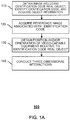
- FIG. 1A is a flowchart of an embodiment of an identification code-based three-dimensional interactive process.
- the process 100 is performed by a client 920 of FIG. 9 and includes:
- the client communicates with the server, such as, for example, to transfer images obtained by a camera on the client side to the server side, and then the server completes all the computation. However, this relies on the network.
- the computations take place at the client.
- the server obtains an image including an identification-coded real object and taken by video-capable equipment, identifies an identification code from the identification-coded real object, and acquires object information corresponding to the identified identification code.
- the object information includes basic information (e.g., object ID) obtained using the identification code.
- the identification code is a bar code or a 2D bar code, which has other information, and the object ID is one type of other information.
- the object information also includes target data obtained from a local database or a network based on the basic information.
- the target information can include a great deal of information. For example, target information includes a list of ingredients of the product, product specification, or a link to a website for promotional purposes.
- the target data includes a three-dimensional image corresponding to the object information.
- the target data include JPEG, TIF, etc.
- the video-capable equipment can be a video camera, mobile equipment having an image capturing function, portable equipment with an image capturing function, etc.
- the identification-coded real object is captured using the video-capable equipment.
- the image including the identification-coded real object is obtained.
- This identification code is identified (e.g., looked up in a database) to obtain the object information included in the identification code.
- the server acquires a reference image associated with the identification code and feature points of the reference image.
- data associated with identification codes is stored in a database.
- the data can include object IDs corresponding to the identification codes, reference images associated with the identification codes, feature points of these reference images, and other such content.
- the server queries the database using an object ID obtained by the identifying of the identification code.
- the server acquires the reference image.
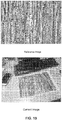
- FIG. 1B is a diagram of an example of a reference image and a current image.
- the server obtains a reference image associated with the identification code. An example of the obtaining of the reference image is provided in operation 210 of FIG. 2A .
- the server obtains the reference image feature points and stores the reference image feature points in the database. An example of the obtaining of the reference image feature points is provided in operation 220 of FIG. 2A .
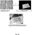
- FIG. 1C is a diagram of an example of a reference image and a current image including a black spot. Using the black spot in the reference image of FIG. 1C as a feature point, the black spot is found in the current image frame using a matching algorithm. Then, a homography matrix is used to compute the relative position of the image capturing equipment with respect to the printed image's position and orientation.
- the server conducts three-dimensional interactions based on the position and/or orientation of the video-capable equipment relative to the identification-coded real object and the object information corresponding to the identification code.
- An example of a three-dimensional interaction includes a person holding a card, and a flying iron man in a video game is controlled by moving the card around.
- a video camera on a side of the television locates the card, and computes, in real time, relative position, orientation, and movement of the card relative to the video camera, and uses the computed position, orientation, and movement to control the flying iron man.
- the user After the obtaining of the position and/or orientation of the video-capable equipment relative to the identification-coded real object, the user, for example, adds object information (e.g., the three-dimensional image of the object) to the identification code-containing image in order to attain a virtual-real composite effect of the object information located at the position of the identification-coded real object and thus be able to interact in a three-dimensional manner.
- object information e.g., the three-dimensional image of the object
- a program identifies a target ID, sets up target information, and provides a button in the program, where the user can activate the button and show the information on the display.
- the server continuously obtains the position and/or orientation of the video-capable equipment relative to the identification-coded real object, and then, in operation 140, the server obtains a relative motion speed, acceleration, or a combination thereof of the video-capable equipment and the identification code or the real object where the identification code is located, and transmits the relative motion speed, acceleration, or a combination thereof of the video-capable equipment and the identification code or the real object where the identification code is located in a predetermined manner to a user interface.
- the predetermined manner is via a data display, a three-dimensional image display, or symbols (such as arrows or bar charts).
- moving the card relative to the video camera allows control of the flying iron man in the video game.
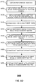
- FIG. 2A is a flowchart of an embodiment of a process for obtaining a position and/or orientation of video-capable equipment relative to an identification-coded real object.
- the process 200 is performed by a client 920 of FIG. 9 and includes:
- the server obtains an identification code reference image based on the obtained identification-coded real object of the image.
- the reference image corresponds to the image including the identification-coded real object.
- FIG. 2B is a diagram of an example of a 2D code. In the example of FIG. 2B , the 2D code that is extracted from the image is used as a reference image, even though the 2D code is not very clear and is rotated.
- the reference image corresponds to a standard identification code image generated based on the image of the identification-coded real object.
- FIG. 2C is a diagram of an example of a standard identification code image.
- a 2D code is generated based on a 2D code generation algorithm.
- Such a 2D code can be stored and used as the standard identification code image because there is no rotation, etc.
- the image including the identification-coded real object is obtained from the image captured by the video-capable equipment, and the object information corresponding to the identification code is identified.
- object information include product type, price, place of manufacture, web links etc.
- a standard identification code image is generated based on the object information and in accordance with an identification code generating algorithm, and the standard identification code image serves as the reference image.
- An example of the identification code generating algorithm includes a "PDF417" code generation algorithm.
- the reference image is stored in a storage device.
- the server obtains size information on the reference image, position information on the reference image, color value information on the reference image, and other information on selected points in the reference image.
- the server detects feature points of the reference image.
- the server detects a plurality of feature points in the reference image, and records coordinate positions of these feature points in the reference image.
- the feature points include vertices of the reference image.
- the reference image corresponds to a standard identification code generated from object information and the standard identification code is a rectangle
- the 4 vertices of the standard identification code are obtained as soon as the standard identification code is generated, and the four vertices serve as the positions of the feature points.
- the matrix calculations utilize at least 4 point pairs. Therefore, if only the vertices are used to perform matrix calculations, the standard identification code should have at least 4 vertices. In another example, the standard identification code should not be triangular because performing matrix calculations with only its 3 vertices is not possible.
- the image used to generate the reference image serves as a first frame image.
- the server obtains the current image including the identification-coded real object.
- the current image is taken by video-capable equipment.
- the server obtains a homography matrix of reference image-to-current image based on reference image and the current image. How to acquire a homography matrix that relates a reference image to a current image (also referred to as a homography matrix of reference image-to-current image) is discussed in FIGS. 3 and 4A .
- the server obtains a position and/or orientation of the video-capable equipment relative to the identification-coded real object based on the homography matrix of reference image-to-current image.
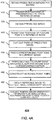
- FIGS. 3 and 4A are flowcharts of examples of processes for acquiring a homography matrix of reference image-to-current image.
- processes 300 and 400 are performed by a client 920 of FIG. 9 and includes:
- FIGS. 3 and 4A include operations that are similar with respect to the descriptions of FIGS. 1 and 2 . Details of the similar operations are omitted for conciseness.
- the server obtains a current image including the identification-coded real object, the current image being captured using video-capable equipment and the identification-coded real object including an identification code.
- the server identifies frames of the current image that includes the identification code.
- the frame in the current image including the identification code that appears for the first time is frame 1.
- the frame in the current image including the identification code that appears for the k-th time is frame k.
- the server identifies the current image based on an identification code identifying algorithm, and obtains a position of the identification code in the current image and positions of at least four vertices of the identification code. Note that because the matrix calculations, in 360, use at least 4 point pair positions, the identification code in 320, is to have at least 4 vertices.
- the server generates a standard identification code image using an identification code generating algorithm, the standard identification code image being generated based on the obtained object information, and regards the standard identification code image as a reference image. At the same time, the server obtains the four vertex positions of the standard identification code image.
- the server obtains feature points (other than the 4 vertices) from the reference image and the positions of these feature points based on a feature point detection algorithm.
- the feature point detection algorithm include FAST (Features from Accelerated Segment Test) or a Harris (Harris Corner Detector) corner detection method.
- more than one feature points are obtained. For example, 6 feature points are obtained.
- the obtained feature points are used in a transformation of the position of the feature points.
- the server constructs matched point pairs based on the four identification code vertices in the reference image and the four identification code vertices in the current image.
- the matched point pairs are the coordinates of the four vertices, e.g., in two images, two points on the upper left hand corners form a matched point pair, e.g., (x1, y1) and (x2, y2)
- the server builds equations based on the matched point pairs and solves the built equations to obtain the homography matrix of reference image-to-current image.
- the equations for estimating the homography matrix are understood by one of ordinary in the art and are omitted for conciseness.
- the server calculates the position and/or orientation information on the video-capable equipment relative to the identification-coded real object based on the homography matrix of reference image-to-current image.
- FIG. 4B is a diagram of an example of a reference image including feature points.
- the points of FIG. 4B which correspond to the dots, are removed from a reference image. The points correspond to the feature points.
- the server obtains a predictive homography matrix.
- the server Before obtaining the homography matrix of reference image-to-current image, the server obtains a predicted image.
- the predicted image corresponds with a forecast image.
- the forecast image predicts a possible arrangement of the reference image in the image that is captured by the camera.
- the predicted image is used to more accurately compute the matched points.
- FIG. 4C is a diagram of an example of a reference image, a predicted image, and a current image.
- the reference image and the image captured by the camera are changed in shape and rotated, and there is a large difference between the image, so computing the black dot's corresponding matching point can lead to errors.
- the predicted image and the image captured by the camera have a smaller difference.
- the server performs reference image feature point matching point calculations based on the predicted image.
- the performance of the reference image feature point matching point calculations based on the predicted image reduces computation volume and increases computation speed.
- the server obtains the predictive homography matrix.
- the server is capable of obtaining the predictive homography matrix based on different combinations of hardware operations and calculation rules. In some embodiments, the calculation is as follows:
- the predictive homography matrix is a b c d e f g h i
- the coordinates of the black dot in the reference image is (x 1 , y 1 )
- pixel values are (27, 58, 68)
- the pixel values of the reference image are computed.
- the predetermined points are all the points in the reference image. In other words, the server obtains the positions of all the reference image points in the predicted image. In some embodiments, the predetermined points are some of the points in the reference image.
- the server obtains a predicted image based on the positions of the predetermined points and the corresponding color values of the predetermined points in the reference image.
- the server transforms the positions of the feature points in the reference image and obtains predicted positions of the reference image feature points in the predicted image. For example, the server transforms positions of 6 feature points in the reference image, and obtains 6 predicted positions of the 6 feature points in the predicted image.
- the server cuts out a part of the predicted image based on a predetermined size and shape around the predicted position of each of the reference image feature points in the predicted image and has the part serve as a predetermined image block corresponding to each feature point. For example, 6 predicted positions of reference image feature points in the predicted image that have already been obtained exist. Thus, for each predicted position, the server cuts out from the predicted image a square (shape) whose center is the predicted position and that has a predetermined size of 9x9 pixels. In other words, the server obtains 6 image blocks with each image block being 9x9 pixels.
- the server finds corresponding positions in the current image based on the predicted positions of the feature points in the predicted image. For example, 6 corresponding positions are found in the current image with respect to the 6 predicted positions of the 6 feature points in the predicted image that have already been obtained.
- the server obtains matched points for the reference image feature points in the current image using a class 2 feature point matching algorithm around each corresponding position in the current image, and within a preset range.
- the class 2 feature point matching algorithm uses the corresponding image block as a standard to obtain the matched points.
- FIG. 4E is a diagram of an example of a reference image, a predicted image, an image block, and a current image.
- the image block is used to obtain a matching point.
- This obtaining of the matching point includes the reference image being transformed by the homography matrix to form a predicted image.
- a feature point (e.g., the black dot) has a coordinate A, and a homography transformation is performed to obtain a corresponding point B.
- a location B In the current frame, there is also a location B, and a 3x3 image block having a location B as its center is selected. Based on position B being the center of the current frame, an additional point C (e.g., in each of the 9 points in the 3x3 image block) is selected, and location C is selected as the center to select the same 3x3 image to and apply the same technique to obtain many image blocks to find the best matching point for the predicted image's position A and the current frame image.
- image block techniques described above include SIFT, SURF, Binary Robust Invariant Scalable Keypoints (BRISK), etc.
- BRISK Binary Robust Invariant Scalable Keypoints
- Examples of the class 2 feature point matching algorithm include template matching, cross correlation, normalized cross correlation, or other feature point matching algorithm with a similar function.
- 6 corresponding positions are found in the current image.
- the corresponding 9x9 pixel image block is used within a preset 15x15 pixel range around the position, and the class 2 feature point matching algorithm is used to find 1 matched point.
- one position of a matched point is obtained in the current image.
- the remaining 5 matched points and their 5 positions in the current image are also found using the class 2 feature point matching algorithm and the corresponding matched blocks.
- the server constructs matched point pairs based on the feature points of the reference image and the matched points in the current image. For example: 6 feature point positions are obtained from 340 of FIG. 3 . The position of one of the feature points in the reference image is (3,9). 6 matched point positions are obtained from 470 of FIG. 4A . The position in the current image of the matched point corresponding to the above feature point is (2,8). Thus, [(3,9);(2,8)] corresponds with one matched point pair. The remaining 5 matched point pairs are obtained in a similar manner for a total of 6 matched point pairs.
- erroneous point pairs are eliminated using a Prosac (Progressive Sample Consensus) algorithm or a Ransac (Random Sample Consensus) algorithm. For example, 6 matched point pairs have already been obtained, and an erroneous matched point pair is eliminated using the Prosac or Ransac algorithm, so that 5 matched point pairs remain.
- Prosac Processive Sample Consensus
- Ransac Random Sample Consensus
- the server obtains a homography matrix of reference image-to-current image based on the matched point pairs.
- a singular value decomposition algorithm a LM iterative optimization algorithm (Levenberg-Marquardt method) or a Gauss-Newton algorithm is used to calculate the homography matrix of reference image-to-current image based on the matched point pairs.
- the server acquires a position and/or orientation information on the video-capable equipment relative to the identification-coded real object based on the homography matrix of reference image-to-current image.
- FIG. 5A is a flowchart of an embodiment of a process for obtaining a predictive homography matrix.
- the process 500 is an implementation of operation 410 and includes:
- the server acquires a reference image S.
- FIG. 5B is a diagram of another example of a reference image, a predicted image, and a current image.
- the reference image is pre-stored in equipment, is an image taken by video-capable equipment, or an otherwise acquired image. After the reference image is acquired, the reference image can be stored in a storage device.
- size information on the reference image, position information on the reference image, color value information on the reference image, and other such information on selected points in the reference image is obtained.
- the server obtains a first image A that was captured using the video-capable equipment and that contains a reference image real object.
- An example of the first image A includes a frame obtained by the video-capable equipment that has a reference image.
- the reference image real object refers to a reference image that exists in a physical form.
- FIG. 5C is a diagram of an example of a reference image real object. Examples of the reference image that exists in a physical form include a typed reference image or a printed reference image. For example, if the reference image is a photograph taken of a real object (e.g., a teapot), the reference image real object is a printed copy of an image of the teapot.
- the reference image refers to the image that is stored, and the reference image real object refers to the picture that is printed with the image, or a photograph of the image, or the printed sheet of paper with the picture of the bark.
- the server obtains a second image B including a reference image real object, the second image B being taken using video-capable equipment.
- the first and second images A and B are the first and second frames of the images obtained from the video camera that have the reference image.
- the server obtains a homography matrix of reference image S-to-second image B and a homography matrix of first image A-to-second image B based on the reference image S, the first image A, and the second image B.
- An example of a homography matrix is a b c d e f g h i .
- FIG. 5D is a flowchart of an embodiment of a process for obtaining a homography matrix of reference image S-to-second image B and a homography matrix of first image A-to-second image B.
- the process 5400 is an implementation of operation 540 and includes: In 5410, the server obtains a reference image S, and obtains feature points in the reference image S and positions of the feature points based on a feature point detection algorithm. Examples of the feature point detection algorithm include the FAST (Features from Accelerated Segment Test) or the Harris (Harris Corner Detector) corner detection method.
- FAST Features from Accelerated Segment Test
- Harris Harris
- FIG. 5E is a diagram of an example of a reference point.
- the dot of FIG. 5E in the image corresponds to a feature point.
- the feature point includes data with coordinates (257, 80) and the nine pixels surrounding the feature point (based on gray scale values) are 125 94 34 58 58 63 156 179 169 .
- the server obtains feature points in second image B and positions of the feature points based on a feature point detection algorithm.
- the feature points in second image B are obtained in a manner similar to the obtaining of the feature points in the first image A.
- the server obtains matched points (and their positions) in the second image B for the feature points in the reference image S based on a class 1 feature point matching algorithm.
- the class 1 feature point matching algorithm include the SIFT method, the SURF method, and other feature point matching algorithms with similar functions.
- FIG. 5F is a diagram of another example of a reference image and a current image.
- the server constructs matched point pairs based on the feature points in the reference image and the matched points in the second image B.
- the server eliminates erroneous matched point pairs from the matched point pairs based on the Prosac algorithm or the Ransac algorithm.
- the server obtains a homography matrix of reference image-to-second image B based on the matched point pairs.
- the server obtains feature points in the first image A and positions of the feature points based on a feature point detection algorithm.
- the server obtains the points (and their positions) in the first image A matching the feature points in the reference image S based on a class 1 feature point matching algorithm.
- the server constructs matched point pairs based on the feature points in the reference image and the matched points in the first image A. In some embodiments, the server eliminates erroneous matched point pairs from among the matched point pairs based on the Prosac algorithm or the Ransac algorithm.
- the server obtaining a homography matrix of reference image-to-first image A based on the matched point pairs, the matched point pairs being matched based on the feature points in the reference image and the matched points in the first image A.
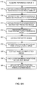
- FIG. 6A is a flowchart of an embodiment of a process for obtaining matched points based on a predictive homography matrix.
- the process 600 is performed by a client 920 of FIG. 9 and includes: As an example, this process describes how to obtain a predictive homography matrix based on a reference image and how to obtain matched points based on the predictive homography matrix.
- the server acquires a reference image S.
- All reference images refer to this reference image.
- the reference image is marked with the symbol S.
- FIG. 6B is a diagram of examples of reference images.
- the reference image can be pre-stored in equipment, the reference image can be an image taken by video-capable equipment, or the reference image can be an otherwise acquired image. After the reference image is acquired, size information on the reference image, position information on the reference image, color value information on the reference image, and other such information on selected points in the reference image can be obtained.
- the server obtains a current image including a reference image real object, the current image being captured using video-capable equipment.
- the reference image real object refers to a reference image that exists in a physical form. Examples of reference image that exists in physical form include a typed reference image or a printed reference image.
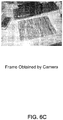
- FIG. 6C is a diagram of an example of a frame. In the event that the reference image corresponds to a photograph taken of a current real object (e.g., a photo of a teapot), the reference image real object can be the current real object indicated by the reference image.
- the server obtains feature points in this reference image and positions of the feature points.
- the server obtaining the feature points and the positions of the feature points based on a feature point detection algorithm.
- the feature point detection algorithm includes FAST, Harris corner detection algorithm, etc.
- a plurality of feature points are obtained.
- 6 feature points are obtained.
- FIG. 6D is a diagram of another example of a reference image including a feature point.
- the black dot in the image of FIG. 6D is a feature point
- the feature point has the coordinates (257,80) and is the center point of nine pixels (assuming the nine pixels are of a black and white image).
- the server obtains a predictive homography matrix for a predicted image based on the reference image.
- the predicted image corresponds to a forecast image.
- the server performs reference image feature point matching point calculations based on the predicted image. The performance of the reference image feature point matching point calculations based on the predicted image reduces computation volume and increases computation speed.
- the server obtains the predictive homography matrix for the predicted image.
- the server can obtain a predictive homography matrix based on different combinations of hardware operation and rules of computation.
- the process 500 of FIG. 5A for obtaining a predictive homography matrix is provided.
- the server transforms positions of predetermined points in the reference image based on the predictive homography matrix, and obtains predicted positions of the reference image predetermined points in the predicted image based on the transformed positions of predetermined points.
- the predetermined points are all points in the reference image.
- the predicted positions are obtained for all reference image points in the predicted image.
- only some feature points and their surrounding pixels are computed; however, all the points can be computed.
- the server obtains the predicted image based on the predicted positions of the predetermined points and corresponding color values of the predetermined points in the reference image.
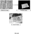
- FIG. 6E is a diagram of an example of a reference image, a predicted image, and a current image.
- the predicted image and the current image are very similar to the reference image.
- the server transforms the positions of the feature points in the reference image based on the predictive homography matrix, and obtains predicted positions of the reference image feature points in the predicted image based on the transformed positions of the feature points. For example, the server transforms the positions of 6 feature points in the reference image, and obtains 6 predicted positions of the 6 feature points in the predicted image.
- the server cuts out a part of the predicted image according to a predetermined size and shape around a predicted position of each feature point in the predicted image, and has the part serve as an image block corresponding to each feature point. For example, 6 predicted positions of reference image feature points exist in the predicted image that has already been obtained. Thus, for each predicted position, the server cuts out 9x9 pixels from the predicted image with the center as the each predicted position. In other words, the server obtains 6 image blocks, each image block corresponding with 9x9 pixels.
- the server finds corresponding positions in the current image based on the predicted positions of the feature points in the predicted image.
- the use of the predicted positions aid in finding corresponding positions in the current image faster. For example, 6 predicted positions of 6 feature points in the obtained predicted image exist, and 6 corresponding positions are found in the current image.
- the server obtains points (and their positions) matching the reference image feature points in the current image around each corresponding position in the current image, and within a preset range based on a class 2 feature point matching algorithm which uses the corresponding image block as a standard.
- the class 2 feature point matching algorithm includes a template matching algorithm, cross correlation algorithm, a normalized cross correlation, or other feature point matching algorithm with a similar function. For example, 6 corresponding positions are found in the current image. For one of these positions, an obtained corresponding 9x9 pixel image block is used within a preset 15x15 pixel range around the position, and the server finds one matched point based on the feature point matching algorithm. In other words, one position and a corresponding matched point are obtained in the current image. The remaining 5 matched points and their 5 positions in the current image are also found in the above manner.
- FIG. 7A is a flowchart of another embodiment of a process for obtaining a homography matrix of reference image-to-current image. Some of the operations of process 600 may be repeated in process 700 and will not be discussed further for conciseness.
- the process 700 is performed by a client 920 of FIG. 9 and includes: In 710, the server acquires a reference image S. (All reference images in this embodiment are referred to this reference image. For convenience, the reference image is marked with the symbol S.)
- the server obtains a current image including a reference image real object, the current image being captured using video-capable equipment.
- the server obtains feature points in the reference image and positions of the feature points.
- the server obtains points (and positions of the points) in the current image matching the feature points of the reference image.
- the points in the current image matching the feature points of the reference image can be obtained in various ways.
- the present embodiment preferably uses the way described by the process 600 of FIG. 6A .
- the reference image and the current image described in process 600 of FIG. 6A correspond to the reference image and current image, respectively, described in the process 700 of FIG. 7A .
- the server constructs matched point pairs based on the feature points in the reference image and the matched points in the current image.
- the obtained positions within the reference image of the reference image feature points and the obtained positions in the current image of the current image matched points constitute the matched point pairs.
- the server obtains 6 feature point positions.
- the position of one of the feature points in the reference image is (3,9).
- the server obtains 6 matched point positions in the current image.
- the position in the current image of the matched point corresponding to the feature point is (2,8).
- [(3,9); (2,8)] constitutes one matched point pair.
- FIG. 7B is a diagram of another example of a reference image and a current image.
- the remaining 5 matched point pairs are obtained in a similar manner for a total of 6 matched point pairs.
- a Prosac or Ransac algorithm is performed to eliminate erroneous point pairs.
- the server eliminates an erroneous matched point pair based on the Prosac algorithm or the Ransac algorithm. Accordingly, 5 matched point pairs remain.
- the server obtains a homography matrix of reference image-to-current image based on the matched point pairs.
- the server calculates the homography matrix of reference image-to-current image based on a singular value decomposition algorithm, LM iterative algorithm, or a Gauss-Newton algorithm. For example, the homography matrix of reference image-to-current image is calculated based on the remaining 5 matched point pairs and the singular value decomposition algorithm.
- FIG. 8 is a structural block diagram of an embodiment of an identification code-based three-dimensional interactive system.
- the system 800 performs the process 100 and includes an identification code acquiring and identifying module 810, a reference image acquiring module 820, a position and orientation acquiring module 830, and an interaction module 840.
- the identification code acquiring and identifying module 810 obtains images containing identification-coded real objects, the images being taken by video-capable equipment and identifies object information corresponding to identification codes from the identification-coded real objects.
- the reference image acquiring module 820 acquires reference images associated with the identification codes and feature points of the reference images.
- the position and orientation acquiring module 830 obtains positions and/or orientations on the video capable equipment relative to the identification-coded real objects based on the reference images and the feature points of the reference images.
- the interaction module 840 conducts three-dimensional interactions based on the positions and/or orientations of the video-capable equipment relative to the identification-coded real objects and the object information corresponding to the identification codes.
- the interaction module 840 is further configured to: acquire three-dimensional images of the identification-coded real objects based on the object information, add the three-dimensional images one-by-one onto the identification codes in current images taken by the video-capable equipment or onto the object positions where the identification codes are located.
- a 2D barcode exists on a package of a product, the 2D barcode only occupies a small area of the package.
- the display can add 3D images to the 2D barcode image, or add to the package area of the 2D barcode.
- 3D animation can be added based on a computed position and orientation.
- the interaction module 840 is further configured to: acquire relative motion speed, acceleration or both of the video-capable equipment and the identification code or real object where the identification code is located based on the images of identification-coded real objects taken with continuous-frame, video-capable equipment, continuously acquire the positions and orientations of the video-capable equipment relative to the identification-coded real object, and convey in a predetermined manner the motion speed, acceleration or both to a user interface.
- the reference image acquiring module 820 is further configured to: acquire an initial image including an identification-coded real object from an image, the image being captured using the video-capable equipment, obtain a reference image based on the initial image, and obtain feature points and positions of the feature points in the reference image based on a feature point detection algorithm.
- the position and orientation acquiring module 830 is further configured to: obtain a current image including an identification-coded real object, the current image being taken with video-capable equipment, acquire a homography matrix of reference image-to-current image based on the reference image and the current image, and obtain position and/or orientation information on the video-capable equipment relative to the identification-coded real objects based on the homography matrix.
- FIG. 9 is a structural diagram illustrating an embodiment of an identification code-based three-dimensional interactive system.
- the system 900 includes a server 910 connected to a client 920 via a network 930.
- an image is taken using video-capable equipment 940 and the client 920 sends the image including an identification-coded real object to the server 910 to conduct three-dimensional interactions.
- the obtaining of the homography matrix of reference image-to-current image based on the reference image and the current image includes obtaining positions of the 4 vertices of the identification code in the initial image, constructing matched point pairs based on the 4 vertices of the reference image and the 4 vertices of the identification code in the initial image, and obtaining a homography matrix for reference image-to-current image transformation based on the matched point pairs.
- the obtaining of the homography matrix of reference image- to-current image based on the reference image and the current image includes obtaining points in the current image matching the feature points of the reference image based on a feature point matching algorithm, constructing matched point pairs based on the feature points in the reference image and the matched points in the current image, and obtaining a homography matrix of reference image-to-current image based on the matched point pairs.
- the modules described above can be implemented as software components executing on one or more general purpose processors, as hardware such as programmable logic devices and/or Application Specific Integrated Circuits designed to perform certain functions or a combination thereof.
- the modules can be embodied by a form of software products which can be stored in a nonvolatile storage medium (such as optical disk, flash storage device, mobile hard disk, etc.), including a number of instructions for making a computer device (such as personal computers, servers, network equipment, etc.) implement the methods described in the embodiments of the present invention.
- the modules may be implemented on a single device or distributed across multiple devices. The functions of the modules may be merged into one another or further split into multiple sub-modules.
- RAM random-access memory
- ROM read-only memory
- electrically programmable ROM electrically erasable programmable ROM
- registers hard drives, removable disks, CD-ROM, or any other forms of storage media known in the technical field.
Landscapes
- Engineering & Computer Science (AREA)
- Theoretical Computer Science (AREA)
- Physics & Mathematics (AREA)
- General Physics & Mathematics (AREA)
- General Engineering & Computer Science (AREA)
- Computer Vision & Pattern Recognition (AREA)
- Artificial Intelligence (AREA)
- Health & Medical Sciences (AREA)
- Electromagnetism (AREA)
- General Health & Medical Sciences (AREA)
- Toxicology (AREA)
- Human Computer Interaction (AREA)
- Data Mining & Analysis (AREA)
- Life Sciences & Earth Sciences (AREA)
- Bioinformatics & Cheminformatics (AREA)
- Bioinformatics & Computational Biology (AREA)
- Evolutionary Biology (AREA)
- Evolutionary Computation (AREA)
- Image Analysis (AREA)
- Image Processing (AREA)
Applications Claiming Priority (4)
| Application Number | Priority Date | Filing Date | Title |
|---|---|---|---|
| CN201310047346.2A CN103971400B (zh) | 2013-02-06 | 2013-02-06 | 一种基于标识码的三维交互的方法和系统 |
| US14/172,654 US9195871B2 (en) | 2013-02-06 | 2014-02-04 | Information processing method and system |
| EP14710073.9A EP2954390B1 (de) | 2013-02-06 | 2014-02-05 | Informationsverarbeitungsverfahren und -system |
| PCT/US2014/014792 WO2014123954A2 (en) | 2013-02-06 | 2014-02-05 | Information processing method and system |
Related Parent Applications (2)
| Application Number | Title | Priority Date | Filing Date |
|---|---|---|---|
| EP14710073.9A Division EP2954390B1 (de) | 2013-02-06 | 2014-02-05 | Informationsverarbeitungsverfahren und -system |
| EP14710073.9A Division-Into EP2954390B1 (de) | 2013-02-06 | 2014-02-05 | Informationsverarbeitungsverfahren und -system |
Publications (1)
| Publication Number | Publication Date |
|---|---|
| EP3674853A1 true EP3674853A1 (de) | 2020-07-01 |
Family
ID=51240847
Family Applications (2)
| Application Number | Title | Priority Date | Filing Date |
|---|---|---|---|
| EP14710073.9A Active EP2954390B1 (de) | 2013-02-06 | 2014-02-05 | Informationsverarbeitungsverfahren und -system |
| EP20156185.9A Withdrawn EP3674853A1 (de) | 2013-02-06 | 2014-02-05 | Bildbasiertes informationsverarbeitungsverfahren und -system |
Family Applications Before (1)
| Application Number | Title | Priority Date | Filing Date |
|---|---|---|---|
| EP14710073.9A Active EP2954390B1 (de) | 2013-02-06 | 2014-02-05 | Informationsverarbeitungsverfahren und -system |
Country Status (5)
| Country | Link |
|---|---|
| US (4) | US9195871B2 (de) |
| EP (2) | EP2954390B1 (de) |
| CN (1) | CN103971400B (de) |
| TW (1) | TWI587205B (de) |
| WO (1) | WO2014123954A2 (de) |
Families Citing this family (42)
| Publication number | Priority date | Publication date | Assignee | Title |
|---|---|---|---|---|
| CN105378593B (zh) | 2012-07-13 | 2019-03-01 | 索尼深度传感解决方案股份有限公司 | 利用手上的奇异兴趣点基于手势进行人机同步交互的方法和系统 |
| CN103971400B (zh) * | 2013-02-06 | 2018-02-02 | 阿里巴巴集团控股有限公司 | 一种基于标识码的三维交互的方法和系统 |
| EP2891950B1 (de) | 2014-01-07 | 2018-08-15 | Sony Depthsensing Solutions | Mensch-zu-Computer-Navigationsverfahren auf Grundlage natürlicher, dreidimensionaler Handgesten |
| US9846948B2 (en) * | 2014-07-09 | 2017-12-19 | Ditto Labs, Inc. | Systems, methods, and devices for image matching and object recognition in images using feature point optimization |
| US10462406B2 (en) * | 2014-08-01 | 2019-10-29 | Sony Corporation | Information processing apparatus and information processing method |
| CN105515935B (zh) * | 2014-09-22 | 2019-09-27 | 阿里巴巴集团控股有限公司 | 一种交互信息中doi的处理方法及装置 |
| WO2016095438A1 (zh) * | 2014-12-19 | 2016-06-23 | 深圳市金立通信设备有限公司 | 一种二维码操控方法及终端 |
| US20170061700A1 (en) * | 2015-02-13 | 2017-03-02 | Julian Michael Urbach | Intercommunication between a head mounted display and a real world object |
| US11308642B2 (en) * | 2017-03-30 | 2022-04-19 | Visualimits Llc | Automatic region of interest detection for casino tables |
| US10217312B1 (en) * | 2016-03-30 | 2019-02-26 | Visualimits, Llc | Automatic region of interest detection for casino tables |
| US10650550B1 (en) * | 2016-03-30 | 2020-05-12 | Visualimits, Llc | Automatic region of interest detection for casino tables |
| CN105868733A (zh) * | 2016-04-21 | 2016-08-17 | 腾讯科技(深圳)有限公司 | 一种人脸活体验证方法及装置 |
| KR101768532B1 (ko) * | 2016-06-08 | 2017-08-30 | 주식회사 맥스트 | 증강 현실을 이용한 화상 통화 시스템 및 방법 |
| CN106331639B (zh) * | 2016-08-31 | 2019-08-27 | 浙江宇视科技有限公司 | 一种自动确定摄像机位置的方法及装置 |
| FR3055446A1 (fr) * | 2016-09-01 | 2018-03-02 | Arjo Solutions | Procede et syteme de generation de la signature d'une surface |
| US9871774B1 (en) * | 2016-09-29 | 2018-01-16 | International Business Machines Corporation | Secured file transfer management on augmented reality (AR) and virtual reality (VR) devices |
| US10453204B2 (en) * | 2016-12-06 | 2019-10-22 | Adobe Inc. | Image alignment for burst mode images |
| US10417738B2 (en) | 2017-01-05 | 2019-09-17 | Perfect Corp. | System and method for displaying graphical effects based on determined facial positions |
| CN107633526B (zh) | 2017-09-04 | 2022-10-14 | 腾讯科技(深圳)有限公司 | 一种图像跟踪点获取方法及设备、存储介质 |
| CN109525538B (zh) * | 2017-09-20 | 2021-08-24 | 丰盛数位有限公司 | 用于增强现实认证的互动方法及系统 |
| TWI649998B (zh) * | 2017-11-21 | 2019-02-01 | 鴻海精密工業股份有限公司 | 立體影像顯示方法及裝置 |
| CN108022301B (zh) * | 2017-11-23 | 2020-05-19 | 腾讯科技(上海)有限公司 | 一种图像处理方法、装置以及存储介质 |
| CN108711188A (zh) * | 2018-02-24 | 2018-10-26 | 石化盈科信息技术有限责任公司 | 一种基于ar的工厂实时数据展示方法及系统 |
| CN110544280B (zh) * | 2018-05-22 | 2021-10-08 | 腾讯科技(深圳)有限公司 | Ar系统及方法 |
| EP3667236B1 (de) * | 2018-12-13 | 2023-09-06 | Ordnance Survey Limited | Verfahren zur bestimmung von positionsdaten |
| CN109815764B (zh) * | 2019-01-16 | 2022-04-08 | 王诗会 | 图像内部机读信息的读取方法及系统 |
| CN111754449B (zh) * | 2019-03-27 | 2024-10-22 | 北京外号信息技术有限公司 | 基于光通信装置的场景重构方法和相应的电子设备 |
| CN110210584B (zh) * | 2019-05-14 | 2022-10-21 | 武汉工程大学 | 一种基于改进surf复合算法的高速动态二维码识别方法 |
| CN110852951B (zh) * | 2019-11-08 | 2023-04-07 | Oppo广东移动通信有限公司 | 图像处理方法、装置、终端设备及计算机可读存储介质 |
| US11354883B2 (en) | 2019-12-30 | 2022-06-07 | Sensetime International Pte. Ltd. | Image processing method and apparatus, and electronic device |
| SG10201913798WA (en) * | 2019-12-30 | 2021-07-29 | Sensetime Int Pte Ltd | Image processing method and apparatus, and electronic device |
| CN111290676B (zh) * | 2020-03-02 | 2021-02-12 | 北京金山安全软件有限公司 | 客户端中指定区域的图片的截取方法、装置及设备 |
| EP3893144A1 (de) * | 2020-04-06 | 2021-10-13 | Deutsche Post AG | Eindeutige objektoberflächen-id |
| CN113853577A (zh) * | 2020-04-28 | 2021-12-28 | 深圳市大疆创新科技有限公司 | 图像的处理方法及装置、可移动平台及其控制终端、计算机可读存储介质 |
| US11295989B2 (en) | 2020-05-26 | 2022-04-05 | Taiwan Semiconductor Manufacturing Co., Ltd. | Gate structures for semiconductor devices |
| US11416079B2 (en) | 2020-12-03 | 2022-08-16 | Motorola Mobility Llc | Snap motion gesture detection and response |
| JP7643118B2 (ja) * | 2021-03-19 | 2025-03-11 | 株式会社リコー | 情報処理システム、位置管理方法、情報処理装置及びプログラム |
| CN113051953B (zh) * | 2021-04-08 | 2024-11-26 | 广州百视信通智能科技有限公司 | 一种基于二维码定位的ar虚拟商品展示方法 |
| CN113128448B (zh) * | 2021-04-29 | 2024-05-24 | 平安国际智慧城市科技股份有限公司 | 基于肢体识别的视频匹配方法、装置、设备及存储介质 |
| EP4254336A1 (de) * | 2022-03-30 | 2023-10-04 | Auki Labs AG | Computerimplementiertes verfahren zur lokalisierung einer elektronischen vorrichtung in einem koordinatensystem |
| CN115356840A (zh) * | 2022-09-01 | 2022-11-18 | 广东粤港澳大湾区黄埔材料研究院 | 一种显微镜的锁焦方法及装置 |
| CN116309824B (zh) * | 2023-01-13 | 2026-03-13 | 岭东核电有限公司 | 地面水迹识别方法、装置、计算机设备和存储介质 |
Citations (2)
| Publication number | Priority date | Publication date | Assignee | Title |
|---|---|---|---|---|
| US20040028258A1 (en) * | 2002-08-09 | 2004-02-12 | Leonid Naimark | Fiducial detection system |
| US20120327117A1 (en) * | 2011-06-23 | 2012-12-27 | Limitless Computing, Inc. | Digitally encoded marker-based augmented reality (ar) |
Family Cites Families (14)
| Publication number | Priority date | Publication date | Assignee | Title |
|---|---|---|---|---|
| JP3086151B2 (ja) | 1995-05-18 | 2000-09-11 | シャープ株式会社 | 二次元バーコード処理機能付き情報処理装置 |
| AU5272901A (en) | 2000-04-18 | 2001-10-30 | Amaskorea Co., Ltd. | Method for producing identification code, and method and system for giving electronic notice service and electronic meter reading service by using the same |
| US6634552B2 (en) * | 2001-09-26 | 2003-10-21 | Nec Laboratories America, Inc. | Three dimensional vision device and method, and structured light bar-code patterns for use in the same |
| KR100560735B1 (ko) | 2002-05-06 | 2006-03-14 | 이승철 | 식별코드를 이용한 맵정보 검색 방법 |
| US8073196B2 (en) * | 2006-10-16 | 2011-12-06 | University Of Southern California | Detection and tracking of moving objects from a moving platform in presence of strong parallax |
| US20100020970A1 (en) * | 2006-11-13 | 2010-01-28 | Xu Liu | System And Method For Camera Imaging Data Channel |
| CN101339654A (zh) | 2007-07-04 | 2009-01-07 | 北京威亚视讯科技有限公司 | 一种基于标志点的增强现实三维注册方法和系统 |
| US20100045701A1 (en) * | 2008-08-22 | 2010-02-25 | Cybernet Systems Corporation | Automatic mapping of augmented reality fiducials |
| CN102254345A (zh) | 2011-06-30 | 2011-11-23 | 上海大学 | 基于云计算的自然特征注册方法 |
| US20130068839A1 (en) * | 2011-09-21 | 2013-03-21 | Symbol Technologies, Inc. | Method of and apparatus for imaging targets by utilizing multiple imaging modules with on-board local microprocessors |
| CN102800065B (zh) * | 2012-07-13 | 2015-07-29 | 苏州梦想人软件科技有限公司 | 基于二维码识别跟踪的增强现实设备及方法 |
| CN102821323B (zh) * | 2012-08-01 | 2014-12-17 | 成都理想境界科技有限公司 | 基于增强现实技术的视频播放方法、系统及移动终端 |
| US20140210857A1 (en) * | 2013-01-28 | 2014-07-31 | Tencent Technology (Shenzhen) Company Limited | Realization method and device for two-dimensional code augmented reality |
| CN103971400B (zh) * | 2013-02-06 | 2018-02-02 | 阿里巴巴集团控股有限公司 | 一种基于标识码的三维交互的方法和系统 |
-
2013
- 2013-02-06 CN CN201310047346.2A patent/CN103971400B/zh not_active Expired - Fee Related
- 2013-07-25 TW TW102126657A patent/TWI587205B/zh not_active IP Right Cessation
-
2014
- 2014-02-04 US US14/172,654 patent/US9195871B2/en active Active
- 2014-02-05 EP EP14710073.9A patent/EP2954390B1/de active Active
- 2014-02-05 WO PCT/US2014/014792 patent/WO2014123954A2/en not_active Ceased
- 2014-02-05 EP EP20156185.9A patent/EP3674853A1/de not_active Withdrawn
-
2015
- 2015-10-16 US US14/885,232 patent/US9430835B2/en active Active
-
2016
- 2016-07-14 US US15/210,034 patent/US9704247B2/en active Active
-
2017
- 2017-06-09 US US15/618,469 patent/US10121099B2/en active Active
Patent Citations (2)
| Publication number | Priority date | Publication date | Assignee | Title |
|---|---|---|---|---|
| US20040028258A1 (en) * | 2002-08-09 | 2004-02-12 | Leonid Naimark | Fiducial detection system |
| US20120327117A1 (en) * | 2011-06-23 | 2012-12-27 | Limitless Computing, Inc. | Digitally encoded marker-based augmented reality (ar) |
Non-Patent Citations (5)
| Title |
|---|
| CHEOK A D ET AL: "Augmented reality camera tracking with homographies", IEEE COMPUTER GRAPHICS AND APPLICATIONS, IEEE SERVICE CENTER, NEW YORK, NY, US, vol. 22, no. 6, 1 November 2002 (2002-11-01), pages 39 - 45, XP011095118, ISSN: 0272-1716, DOI: 10.1109/MCG.2002.1046627 * |
| CHI-LAM LAI ET AL: "Mobile Edutainment with Interactive Augmented Reality Using Adaptive Marker Tracking", PARALLEL AND DISTRIBUTED SYSTEMS (ICPADS), 2012 IEEE 18TH INTERNATIONAL CONFERENCE ON, IEEE, 17 December 2012 (2012-12-17), pages 124 - 131, XP032311065, ISBN: 978-1-4673-4565-1, DOI: 10.1109/ICPADS.2012.27 * |
| JUN REKIMOTO ET AL: "CyberCode: Designing Augmented Reality Environments with Visual Tags", PROCEEDINGS OF DARE 2000 ON DESIGNING AUGMENTED REALITY ENVIRONMENTS , DARE '00, 12 April 2000 (2000-04-12), New York, USA, pages 1 - 10, XP055115977, DOI: 10.1145/354666.354667 * |
| KATO H ET AL: "Marker tracking and HMD calibration for a video-based augmented reality conferencing system", AUGMENTED REALITY, 1999. (IWAR '99). PROCEEDINGS. 2ND IEEE AND ACM INT ERNATIONAL WORKSHOP ON SAN FRANCISCO, CA, USA 20-21 OCT. 1999, LOS ALAMITOS, CA, USA,IEEE COMPUT. SOC, US, 20 October 1999 (1999-10-20), pages 85 - 94, XP010358756, ISBN: 978-0-7695-0359-2, DOI: 10.1109/IWAR.1999.803809 * |
| TAI-WEI KAN ET AL: "Applying QR code in augmented reality applications", PROCEEDINGS OF THE 8TH INTERNATIONAL CONFERENCE ON VIRTUAL REALITY CONTINUUM AND ITS APPLICATIONS IN INDUSTRY, VRCAI '09, 1 January 2009 (2009-01-01), New York, New York, USA, pages 253, XP055103142, ISBN: 978-1-60-558912-1, DOI: 10.1145/1670252.1670305 * |
Also Published As
| Publication number | Publication date |
|---|---|
| US9430835B2 (en) | 2016-08-30 |
| WO2014123954A3 (en) | 2014-10-16 |
| US20160035097A1 (en) | 2016-02-04 |
| US20140217178A1 (en) | 2014-08-07 |
| US20160321814A1 (en) | 2016-11-03 |
| TW201432548A (zh) | 2014-08-16 |
| EP2954390A2 (de) | 2015-12-16 |
| US9704247B2 (en) | 2017-07-11 |
| US9195871B2 (en) | 2015-11-24 |
| CN103971400A (zh) | 2014-08-06 |
| TWI587205B (zh) | 2017-06-11 |
| CN103971400B (zh) | 2018-02-02 |
| US20170277989A1 (en) | 2017-09-28 |
| EP2954390B1 (de) | 2020-04-01 |
| WO2014123954A2 (en) | 2014-08-14 |
| US10121099B2 (en) | 2018-11-06 |
Similar Documents
| Publication | Publication Date | Title |
|---|---|---|
| US10121099B2 (en) | Information processing method and system | |
| US11380017B2 (en) | Dual-view angle image calibration method and apparatus, storage medium and electronic device | |
| Kan et al. | Applying QR code in augmented reality applications | |
| KR101691903B1 (ko) | 광학 캐릭터 인식을 사용하여 증강 현실을 제공하기 위한 방법 및 장치 | |
| US10186084B2 (en) | Image processing to enhance variety of displayable augmented reality objects | |
| US9436883B2 (en) | Collaborative text detection and recognition | |
| US20140210857A1 (en) | Realization method and device for two-dimensional code augmented reality | |
| CN111459269B (zh) | 一种增强现实显示方法、系统及计算机可读存储介质 | |
| WO2014114118A1 (en) | Realization method and device for two-dimensional code augmented reality | |
| Lakshmi et al. | Image registration techniques based on the scale invariant feature transform | |
| Kan et al. | QR code based augmented reality applications | |
| JP6017343B2 (ja) | データベース生成装置、カメラ姿勢推定装置、データベース生成方法、カメラ姿勢推定方法、およびプログラム | |
| Bergig et al. | In-place augmented reality | |
| CN113867875A (zh) | 标记对象的编辑及显示方法、装置、设备、存储介质 | |
| Beglov | Object information based on marker recognition | |
| Phon-Amnuaisuk et al. | Visual-based positioning and pose estimation | |
| Gupta et al. | Image feature detection using an improved implementation of maximally stable extremal regions for augmented reality applications | |
| Xavier Natario Teixeira et al. | Towards transparent markers | |
| Zhang et al. | Research on Mobile Terminal Augmented Reality Application for Cultural Heritage | |
| HK1197487A (en) | Method and system for three dimension interaction based on identification code | |
| Hall | GPU accelerated feature algorithms for mobile devices | |
| Zhu et al. | A Large-Scale VR Panoramic Dataset of QR Code and Improved Detecting Algorithm | |
| HK1197487B (zh) | 一种基於标识码的三维交互的方法和系统 | |
| Teng et al. | QR code based augmented reality performance evaluation and its application | |
| Yang et al. | 9 Scalable Augmented Reality on Mobile |
Legal Events
| Date | Code | Title | Description |
|---|---|---|---|
| PUAI | Public reference made under article 153(3) epc to a published international application that has entered the european phase |
Free format text: ORIGINAL CODE: 0009012 |
|
| AC | Divisional application: reference to earlier application |
Ref document number: 2954390 Country of ref document: EP Kind code of ref document: P |
|
| AK | Designated contracting states |
Kind code of ref document: A1 Designated state(s): AL AT BE BG CH CY CZ DE DK EE ES FI FR GB GR HR HU IE IS IT LI LT LU LV MC MK MT NL NO PL PT RO RS SE SI SK SM TR |
|
| STAA | Information on the status of an ep patent application or granted ep patent |
Free format text: STATUS: THE APPLICATION HAS BEEN WITHDRAWN |
|
| 17P | Request for examination filed |
Effective date: 20201218 |
|
| 18W | Application withdrawn |
Effective date: 20201222 |
|
| RBV | Designated contracting states (corrected) |
Designated state(s): AL AT BE BG CH CY CZ DE DK EE ES FI FR GB GR HR HU IE IS IT LI LT LU LV MC MK MT NL NO PL PT RO RS SE SI SK SM TR |