EP3674835A1 - Electronic device - Google Patents
Electronic device Download PDFInfo
- Publication number
- EP3674835A1 EP3674835A1 EP18881273.9A EP18881273A EP3674835A1 EP 3674835 A1 EP3674835 A1 EP 3674835A1 EP 18881273 A EP18881273 A EP 18881273A EP 3674835 A1 EP3674835 A1 EP 3674835A1
- Authority
- EP
- European Patent Office
- Prior art keywords
- protective member
- electronic device
- middle frame
- display assembly
- magnet
- Prior art date
- Legal status (The legal status is an assumption and is not a legal conclusion. Google has not performed a legal analysis and makes no representation as to the accuracy of the status listed.)
- Pending
Links
Images


Classifications
-
- H—ELECTRICITY
- H05—ELECTRIC TECHNIQUES NOT OTHERWISE PROVIDED FOR
- H05K—PRINTED CIRCUITS; CASINGS OR CONSTRUCTIONAL DETAILS OF ELECTRIC APPARATUS; MANUFACTURE OF ASSEMBLAGES OF ELECTRICAL COMPONENTS
- H05K5/00—Casings, cabinets or drawers for electric apparatus
- H05K5/0017—Casings, cabinets or drawers for electric apparatus with operator interface units
-
- G—PHYSICS
- G06—COMPUTING; CALCULATING OR COUNTING
- G06F—ELECTRIC DIGITAL DATA PROCESSING
- G06F1/00—Details not covered by groups G06F3/00 - G06F13/00 and G06F21/00
- G06F1/16—Constructional details or arrangements
- G06F1/1613—Constructional details or arrangements for portable computers
- G06F1/1633—Constructional details or arrangements of portable computers not specific to the type of enclosures covered by groups G06F1/1615 - G06F1/1626
-
- G—PHYSICS
- G01—MEASURING; TESTING
- G01P—MEASURING LINEAR OR ANGULAR SPEED, ACCELERATION, DECELERATION, OR SHOCK; INDICATING PRESENCE, ABSENCE, OR DIRECTION, OF MOVEMENT
- G01P13/00—Indicating or recording presence, absence, or direction, of movement
-
- G—PHYSICS
- G06—COMPUTING; CALCULATING OR COUNTING
- G06F—ELECTRIC DIGITAL DATA PROCESSING
- G06F1/00—Details not covered by groups G06F3/00 - G06F13/00 and G06F21/00
- G06F1/16—Constructional details or arrangements
- G06F1/1613—Constructional details or arrangements for portable computers
- G06F1/1626—Constructional details or arrangements for portable computers with a single-body enclosure integrating a flat display, e.g. Personal Digital Assistants [PDAs]
-
- G—PHYSICS
- G06—COMPUTING; CALCULATING OR COUNTING
- G06F—ELECTRIC DIGITAL DATA PROCESSING
- G06F1/00—Details not covered by groups G06F3/00 - G06F13/00 and G06F21/00
- G06F1/16—Constructional details or arrangements
- G06F1/1613—Constructional details or arrangements for portable computers
- G06F1/1633—Constructional details or arrangements of portable computers not specific to the type of enclosures covered by groups G06F1/1615 - G06F1/1626
- G06F1/1656—Details related to functional adaptations of the enclosure, e.g. to provide protection against EMI, shock, water, or to host detachable peripherals like a mouse or removable expansions units like PCMCIA cards, or to provide access to internal components for maintenance or to removable storage supports like CDs or DVDs, or to mechanically mount accessories
-
- H—ELECTRICITY
- H01—ELECTRIC ELEMENTS
- H01F—MAGNETS; INDUCTANCES; TRANSFORMERS; SELECTION OF MATERIALS FOR THEIR MAGNETIC PROPERTIES
- H01F7/00—Magnets
- H01F7/06—Electromagnets; Actuators including electromagnets
- H01F7/08—Electromagnets; Actuators including electromagnets with armatures
- H01F7/126—Supporting or mounting
-
- H—ELECTRICITY
- H05—ELECTRIC TECHNIQUES NOT OTHERWISE PROVIDED FOR
- H05K—PRINTED CIRCUITS; CASINGS OR CONSTRUCTIONAL DETAILS OF ELECTRIC APPARATUS; MANUFACTURE OF ASSEMBLAGES OF ELECTRICAL COMPONENTS
- H05K5/00—Casings, cabinets or drawers for electric apparatus
- H05K5/02—Details
- H05K5/03—Covers
-
- G—PHYSICS
- G06—COMPUTING; CALCULATING OR COUNTING
- G06F—ELECTRIC DIGITAL DATA PROCESSING
- G06F2200/00—Indexing scheme relating to G06F1/04 - G06F1/32
- G06F2200/16—Indexing scheme relating to G06F1/16 - G06F1/18
- G06F2200/163—Indexing scheme relating to constructional details of the computer
- G06F2200/1633—Protecting arrangement for the entire housing of the computer
Definitions
- the present application relates to a technical field of communication apparatuses, and more particularly, to an electronic device.
- a rear cover of an electronic device usually protrudes from an outer frame, in order to improve the aesthetics of appearance of the electronic device (such as a mobile phone, a tablet computer, and the like).
- the present disclosure seeks to solve at least one of the technical problems existing in the related art. To this end, the present disclosure proposes an electronic device that has good anti-dropping performance and high reliability.
- An electronic device includes: a middle frame including a sidewall arranged in an encircled manner; a display assembly located at a front side of the middle frame; a rear cover located at a rear side of the middle frame; and a protective member movably provided on the sidewall of the middle frame.
- a front end of the protective member is lower than or flush with an outer surface of the display assembly and a rear end of the protective member is lower than or flush with an outer surface of the rear cover.
- the protective member can move towards the rear side of the middle frame from the initial state such that the rear end of the protective member exceeds the outer surface of the rear cover, thereby protecting the rear cover when the electronic device drops.
- the front end and the rear end of the protective member are lower than or flush with the outer surfaces of the display assembly and the rear cover when in the initial state, and meanwhile, the protective member can move from the initial state towards the rear side of the middle frame such that the rear end of the protective member exceeds the outer surface of the rear cover.
- the protective member can be adjusted to the initial state to improve the aesthetics of the appearance and the hand feeling of the electronic device.
- the protective member When the electronic device is not in use or drops, the protective member can be moved towards the rear side of the middle frame such that the rear end of the protective members exceeds the outer surface of the rear cover, so as to protect the rear cover when the electronic device drops, thereby improving the anti-dropping performance of the electronic device on the premise of ensuring the aesthetics of the appearance and the hand feeling of the electronic device.
- the electronic device has a simple structure and low production cost, hence improving the cost-performance ratio of the electronic device.
- An electronic device includes a middle frame including a sidewall arranged in an encircled manner; a display assembly located at a front side of the middle frame; a rear cover located at a rear side of the middle frame; a protective member provided on the sidewall of the middle frame, wherein the protective member has three position states: an initial position where a the front end of the protective member is lower than or flush with an outer surface of the display assembly, a first position where the front end of the protective member exceeds the outer surface of the display assembly, and a second position where a rear end of the protective member exceeds a surface of the rear cover; a driving assembly configured to drive the protective member to move from the initial position to the first position or drive the protective member to move from the initial position to the second position, when the electronic device drops.
- the protective member having the three position states
- the display assembly and the rear cover can be protected by the protective member and be prevented from being damaged during the fall of the electronic device, which improves the anti-dropping performance of the electronic device.
- the aesthetics of the electronic device can be improved.
- the protective member has a simple structure and low production cost, hence improving the cost-performance ratio of the electronic device.
- the terms “mounted,” “connected,” “coupled” or the like are used broadly.
- the terms may be, for example, fixed connections, detachable connections, or integral connections; may also be mechanical or electrical connections, may also be direct connections or indirect connections via intervening structures; and may also be inner communications of two elements, which can be understood by those skilled in the art according to specific situations.
- an electronic device 100 includes a middle frame 12, a display assembly 2, a rear cover 11 and a protective member 3.
- the electronic device 100 may be a terminal, such as a mobile phone, a tablet computer, and the like.
- the middle frame 12 includes a sidewall arranged in an encircled manner.
- the middle frame 12 can be formed into a rectangular frame structure.
- the display assembly 2 is located at a front side of the middle frame 12 and the rear cover 11 is located at a rear side of the middle frame.
- the rear cover 11 can be formed into a substantially rectangular plate-shaped structure.
- the rear cover 11 can be a glass member or a ceramic member. That is, the rear cover 11 can be made of glass or ceramic.
- the display assembly 2 can be used to display relevant information of the electronic device 100 (such as a menu and an interface of relevant applications).
- the display assembly 2 can also be used as an input apparatus, by which the user can input relevant control information to the electronic device 100.
- the display assembly 2 can be a touch display screen.
- the protective member 3 can be movably arranged to the sidewall of the middle frame 11, and in an initial state, a front end and a rear end of the protective member 3 are lower than or flush with an outer surface of the display assembly 2 and an outer surface of the rear cover 11, respectively.
- the protective member 3 can move towards the rear side of the middle frame 12 from the initial state, such that the rear end of the protective member 3 exceeds the outer surface of the rear cover, thereby protecting the rear cover 11 when the electronic device 100 drops.
- the front end of the protective member 3 is lower than or flush with the outer surface of the display assembly 2 (for example, a front surface in Fig. 1 ) and the rear end of the protective member 3 is lower than or flush with the outer surface of the rear cover 11 (for example, a rear surface in Fig. 1 ).
- the overall appearance of the electronic device 100 can be effectively improved, avoiding that the protective member 3 affects the appearance of the electronic device 100, and meanwhile the hand feeling of the electronic device 100 can be effectively improved.
- the protective member 3 When the rear end of the protective member 3 exceeds the outer surface of the rear cover 11 by moving the protective member 3 towards the rear side of the middle frame 12 from the initial state, an outer periphery of the outer surface of the rear cover 11 is wrapped by the protective member 3 (as illustrated in Figs. 19-26 ).
- the protective member 3 can be pivoted towards or translated towards the rear side of the middle frame 12 such that the rear end of the protective member 3 exceeds the outer surface of the rear cover 11.
- the protective member 3 absorbs the impact of a face, onto which the electronic device drops, on the electronic device 100 to act as a buffer and protect the rear cover 11, so as to effectively prevent the rear cover 11 from being damaged due to fall, thereby protecting the electronic device 100 and improving the anti-dropping performance of the electronic device 100.
- the protective member 3 when in use, can be adjusted into the initial state to improve the aesthetics of the appearance and the hand feeling of the electronic device 100.
- the protective members 3 can move towards the rear side of the middle frame 12 such that the rear end of the protective member 3 exceeds the outer surface of the rear cover 11, so as to protect the rear cover 11 when the electronic device 100 drops.
- an “outer” direction in the present disclosure refers to a direction adjacent to the center of the electronic device 100. Accordingly, an “outer” direction in the present disclosure refers to a direction away from the center of the electronic device 100.
- the front end and the rear end of the protective member 3 are lower than or flush with the outer surfaces of the display assembly 2 and the rear cover 11 when in the initial state, and meanwhile, the protective member 3 can move from the initial state towards the rear side of the middle frame 12 to allow the rear end of the protective member 3 to exceed the outer surface of the rear cover 11.
- the protective member 3 can be adjusted to the initial state to improve the aesthetics of the appearance and the hand feeling of the electronic device 100.
- the protective member 3 can be moved towards the rear side of the middle frame 12 such that the rear end of the protective member 3 exceeds the outer surface of the rear cover 11, so as to protect the rear cover 11 when the electronic device 100 drops, thereby improving the anti-dropping performance of the electronic device 100 on the premise of ensuring the aesthetics of the appearance and the hand feeling of the electronic device 100.
- the electronic device 100 has a simple structure and low production cost, hence improving the cost-performance ratio of the electronic device 100.
- the electronic device 100 may be a mobile phone with a double-sided screen, that is, the electronic device 100 includes another display assembly arranged facing away from the display assembly 2, besides the display assembly 2.
- the other display assembly is provided at the rear side of the middle frame 12 and covered by the rear cover 11.
- the rear cover 11 may be a cover plate for the other display assembly.
- the protective member 3 can move towards the front side of the middle frame 12 such that the front end of the protective member 13 exceeds the outer surface of the display assembly 2, so as to protect the display assembly 2 when the electronic device 100 drops.
- the protective member can be pivoted towards or translated towards the front side of the middle frame 12 such that the front end of the protective member 3 exceeds the outer surface of the display assembly 2.
- the protective member 3 can be moved towards the front side of the middle frame 12 such that an outer periphery of the outer surface of the display assembly 12 is wrapped by the protective member 3 (as illustrated in Figs. 12-18 ).
- the display assembly 2 can be prevented from being damaged when the electronic device 100 drops.
- the electronic device 100 also includes a driving assembly arranged at the middle frame 12.
- the driving assembly is configured to drive the protective member 3 to move to the rear side of the middle frame 12 such that the rear end of the protective member 3 exceeds the outer surface of the rear cover 11, or to drive the protective member 3 to move towards the front side of the middle frame 12 such that the front end of the protective member 3 exceeds the outer surface of the display assembly 2, or to drive the protective member 3 to be restored to the initial state.
- the protective member 3 can be driven to move towards the front side of the middle frame 12 by the driving assembly such that the front end of the protective member 3 exceeds the outer surface of the display assembly 2, and the outer periphery of the outer surface of the display assembly 2 is wrapped by the protective member 3, so as to protect the display assembly 2 by the protective member 3 and prevent the display assembly 2 from being damaged when the electronic device 100 drops.
- the protective member 3 can be driven to move towards the rear side of the middle frame 12 by the driving assembly such that the rear end of the protective member 3 exceeds the outer surface of the rear cover 11 and the outer periphery of the outer surface of the rear cover 11 is wrapped by the protective member 3, so as to protect the rear cover 11 by the protective member 3, thereby preventing the rear cover 11 from being damaged when the electronic device 100 drops.
- the protective member 3 can be first brought into contact with the face, and absorb the impact of the face on the electronic device 100 to play a buffering role, thereby effectively avoiding the damage of the display assembly 2 and the rear cover 11 due to the fall, further protecting the electronic device 100 and improving the anti-dropping performance of the electronic device 100.
- the electronic device 100 can be provided with a sensor configured to sense a dropping state of the electronic device 100, and the sensor is coupled with the driving assembly. Specifically, when the electronic device 100 drops, the sensor can sense whether a surface of the electronic device 100 facing towards the face is the display assembly 2 or the rear cover 11, and the driving assembly drives the protective member 3 to move according to a sensing result of the sensor, so as to protect the display assembly 2 and the rear cover 11 by the protective member 3.
- the driving assembly includes a driving member 43, a first magnet 41, and at least one second magnet 42.
- One end of the driving member 43 is coupled with the first magnet 41, and the other end of the driving member 43 is fitted with the protective member 3.
- At least one of the above second magnets 42 is suitable to cooperate with the first magnet 41 to urge the driving member 43 to drive the protective member to move towards the rear side of the middle frame 12, such that the rear end of the protective member 3 exceeds the outer surface of the rear cover 11; or at least one of the above second magnets 42 is suitable to cooperate with the first magnet 41 to urge the driving member 43 to drive the protective member 3 to move towards the front side of the middle frame 12, such that the front end of the protective member 3 exceeds the outer surface of the display assembly 2.
- the first magnet 41 is provided with a mounting hole 411
- the driving member 43 is provided with a mounting post 430
- the mounting post 430 is fitted with the mounting hole 411 to fix the first magnet 41 on the driving member 43.
- the structure is simple and the mounting is convenient.
- one second magnet 42 or a plurality of second magnets 42 can be provided.
- the second magnet 42 can be arranged opposite the first magnet 41.
- the driving member 43 when the electronic device 100 drops, the driving member 43 can be driven to move through the cooperation between the second magnet 42 and the first magnet 41, and further the driving member 43 drives the protective member 3 to move to the front side or the rear side of the middle frame 12, such that the front end of the protective member 3 exceeds the outer surface of the display assembly 2 or the rear end of the protective member 3 exceeds the outer surface of the rear cover 11.
- a repulsive force or an attractive force can be generated between the second magnet 42 and the first magnet 41 to urge the protective member 3 to move to the front side of the middle frame 12 or the rear side of the middle frame 12 by the driving member 43, such that the front end of the protective member 3 exceeds the outer surface of the display assembly 2 or the rear end of the protective member 3 exceeds the outer surface of the rear cover 11.
- At least one of the plurality of second magnets 42 cooperates with the first magnet 41 to urge the protective member 3 to move to the front side of the middle frame 12 or the rear side of the middle frame 12 by means of the driving member 43, such that the front end of the protective member 3 exceeds the outer surface of the display assembly 2 or the rear end of the protective member 3 exceeds the outer surface of the rear cover 11.
- the second magnet 42 there is one second magnet 42 and the second magnet 42 is arranged at a front side of the first magnet 41.
- the second magnet 42 is arranged adjacent to the display assembly 2.
- an attractive force can be generated between the first magnet 41 and the second magnet 42 to urge the first magnet 41 to move towards a direction close to the second magnet 42, so that the protective member 3 can be driven to move to the front side of the middle frame 12 by the driving member 43, and hence the front end of the protective member 3 exceeds the outer surface of the display assembly 2.
- the display assembly 2 is prevented from being damaged when the electronic device 100 drops.
- one second magnet 42 is provided and arranged at a rear side of the first magnet 41.
- the second magnet 42 is arranged adjacent to the rear cover 11.
- a repulsive force can be generated between the first magnet 41 and the second magnet 42 to move the first magnet 41 towards the direction away from the second magnet 42, so as to drive the protective member 3 to move to the front side of the middle frame 12 by the driving member 43, such that the front end of the protective member 3 exceeds the outer surface of the display assembly 2.
- the display assembly 2 With the protection of the protective member 3 to the display assembly 2, the display assembly 2 is prevented from being damaged when the electronic device 100 drops.
- an attractive force can be generated between the first magnet 41 and the second magnet 42 to move the first magnet 41 towards the direction close to the second magnet 42, so as to drive the protective member 3 to move to the rear side of the middle frame 12 by the driving member 43, such that the rear end of the protective member 3 exceeds the outer surface of the rear cover 11.
- the rear cover is prevented from being damaged when the electronic device 100 drops.
- two second magnets 42 are provided, and the two second magnets 42 are arranged on opposite sides of the first magnet 41 respectively.
- the two second magnets 42 are arranged on the front and rear sides of the first magnet 41 respectively, the second magnet 42 located at the front side of the first magnet 41 is arranged adjacent to the display assembly 2, and the second magnet 42 located at the rear side of the first magnet 41 is arranged adjacent to the rear cover 11.
- the second magnet 42 located at the front side of the first magnet 41 is called as a "front second magnet”
- the second magnet 42 located at the rear side of the first magnet 41 is called as a “rear second magnet.”
- the front second magnet can be coupled with the display assembly 2, and the rear second magnet can be coupled with the rear cover 11.
- the positions of the front second magnet and the rear second magnet can be stabilized.
- an attractive force can be generated between the first magnet 41 and the front second magnet, and at the same time a repulsive force can be generated between the first magnet 41 and the rear second magnet, to move the first magnet 41 towards a direction close to the front second magnet, so as to drive the protective member 3 to move to the front side of the middle frame 12 by the driving member 43, such that the front end of the protective member 3 exceeds the outer surface of the display assembly 2.
- the display assembly 2 With the protection of the protective member 3 to the display assembly 2, the display assembly 2 is prevented from being damaged when the electronic device 100 drops.
- the first magnet 41 is a permanent magnet and the second magnet 42 is an electromagnet.
- a coil of the electromagnet can be powered on to generate an attractive force or a repulsive force between the first magnet 41 and the second magnet 42, such that the movement of the protective member 3 can be realized by the cooperation of the first magnet 41 and the second magnet 42 to protect the electronic device 100.
- the first magnet 41 and the second magnet 42 may be both permanent magnets.
- the first magnet 41 is an electromagnet
- the second magnet 42 is a permanent magnet.
- the movement of the protective member 3 can also be realized by the cooperation of the first magnet 41 and the second magnet 42 to protect the electronic device 100.
- the electronic device 100 further includes: a sensor and a controller.
- the sensor is configured to sense a dropping state of the electronic device 100
- the controller is coupled with the at least one second magnet 42 and the sensor.
- the controller is configured to control the at least one second magnet 42 to be powered on, to drive the protective member 3 to move to a first protection position or a second protection position by the driving member 43, and when the sensor senses the standstill of the electronic device 100, the controller is configured to control the at least one second magnet 42 to be powered off.
- the senor can sense whether the electronic device 100 is in the dropping state, and whether the surface towards the face is the display assembly 2 or the rear cover 11 during the fall of the electronic device 100. After the sensor transmits a detection signal to the controller, the power on and power off of the second magnet 42 are controlled by the controller to control the position of the protective member 3.
- the senor is at least one of a gyroscope, an acceleration sensor, a gravity sensor, an inertia sensor, a camera, a height sensor, and a motion sensor. That is, the sensor may be one or more of the gyroscope, the acceleration sensor, the gravity sensor, the inertial sensor, the camera, the height sensor, and the motion sensor.
- the sensors are the gyroscope and the gravity sensor.
- the protective member 3 is formed with a fitting groove 31, and the other end of the driving member 43 mentioned-above is inserted into the fitting groove 31 to be fitted with the protective member 3.
- the fitting groove 31 is defined in a sidewall of the protective member 3, which is thus convenient for the above end of the driving member 43 to be fitted with the protective member 3.
- the middle frame 12 is formed with a mounting groove 121, and the driving member 43 is arranged in the mounting groove 121.
- the driving member 43 is configured to be elastically deformable in a moving direction of the protective member 3 to normally drive the protective member 3 towards an accommodated position.
- the driving member 43 is elastically deformed under the action of the first magnet 41 and the second magnet 42 and moves towards a direction close to the display assembly 2, and then further drives the protective member 3 to move to the front side of the middle frame 12, such that the front end of the protective member 3 exceeds the outer surface of the display assembly 2.
- the acting force between the first magnet 41 and the second magnet 42 disappears, and the force applied on the driving member 43 and causing its elastic deformation disappears.
- the driving member 43 is restored to a natural state under the action of its elastic force and drives the protective member 3 to move from the front side of the middle frame 12 to the initial state.
- the driving member 43 When the rear cover 11 is falling towards the face during the fall of the electronic device 100, the driving member 43 is elastically deformed under the action of the first magnet 41 and the second magnet 42 and moves towards a direction close to the rear cover 11, and then further drives the protective member 3 to move to the rear side of the middle frame 12, such that the rear end of the protective member 3 exceeds the outer surface of the rear cover 11.
- the acting force between the first magnet 41 and the second magnet 42 disappears, and the force applied on the driving member 43 and causing its elastic deformation disappears.
- the driving member 43 is restored to a natural state under the action of its elastic force and drives the protective member 3 to move from the rear side of the middle frame 12 to the initial state.
- the protective member 3 can be driven from the front or rear side of the middle frame 12 to the initial state by the driving member 43.
- the driving method is simple, reliable and greatly simplifies the structure of the electronic device 100, thereby reducing the number of parts of the electronic device 100 and the cost of the electronic device 100, and improving the cost-performance ratio of the electronic device 100.
- the driving member 43 includes an elastic arm 431 and a snapping head 432.
- the elastic arm 431 is arranged in the mounting groove 121.
- a first movement space 1211 is defined between a side surface of the elastic arm 431 adjacent to the display assembly 2 and an inner wall of the mounting groove 121 opposite to the elastic arm 431.
- a second movement space 1212 is defined between a side surface of the elastic arm 431 away from the display assembly 2 and an inner wall of the mounting groove 121 opposite to the elastic arm 431.
- the mounting groove 121 is formed in the sidewall of the middle frame 12.
- the mounting groove 121 can be formed as a through groove penetrating along a thickness direction of the sidewall of the middle frame 12.
- the elastic arm 431 can be formed as a long strip.
- the first movement space 1211 is defined between a front surface of the elastic arm 431 and an inner wall of the mounting groove 121 opposite to the elastic arm 431, and the second movement space 1212 is defined between a rear surface of the elastic arm 431 and an inner wall of the mounting groove 121 opposite to the elastic arm 431.
- the snapping head 432 is arranged on the elastic arm 431 and is suitable to be inserted into the fitting groove 31 to be fitted with the protective member 3.
- the snapping head 432 can be arranged on a side of the elastic arm 431 away from a center of the middle frame 12.
- the snapping head 432 can be inserted into the fitting groove 32 to be snapped with the fitting groove 31.
- the protective member 3 can be firmly coupled to the middle frame 12 by the driving member 43.
- the driving member 43 is elastically deformed, the protective member 3 can be driven by the fitting of the inner wall of the fitting groove 31 and the snapping head 432.
- the elastic arm 431 is movable in a direction close to and away from the center of the middle frame 12, such that the snapping head 432 is movable between a first position where the snapping head 432 is fitted with the fitting groove 31 and a second position where the snapping head 432 is separated from the fitting groove 31.
- the elastic arm 431 can be arranged in the mounting groove 121 and elastically deformable in a direction close to and away from the center of the middle frame 12 (for example, a left-right direction in Fig. 2 ).
- the elastic deformation of the elastic arm 431 can move the snapping head 432 between the first position where the snapping head 432 is fitted with the fitting groove 31 and the second position where the snapping head 432 is separated from the fitting groove 31, further simplifying the structure of the middle frame 12, reducing the number of parts of the middle frame 12, and lowering the overall cost of the electronic device 100.
- an inner wall of the protective member 3 can press the snapping head 432 to allow the elastic arm 431 to be elastically deformed towards the direction close to the center of the middle frame 12.
- the elastic arm 431 can move towards the direction away from the center of the middle frame 12 to restore the deformation, so as to urge the snapping head 432 to move towards a direction close to the fitting groove 31 such that the snapping head 432 is inserted into the fitting groove 31 to be fitted the fitting groove 31.
- the snapping head 432 can be pressed in the direction close to the center of the middle frame 12, such that the snapping head 432 is separated from the fitting groove 32, and hence the protective member 3 can be detached from the middle frame 12 conveniently.
- the driving member 43 is integrally arranged on the middle frame 12.
- the driving member 43 can be integrally arranged on the middle frame 12 of the middle frame 12.
- the processing technic of the middle frame 12 can be simplified, the processing cost can be reduced, and the overall structural strength of the driving member 43 can be improved.
- the driving member 43 can be integrally formed with the middle frame 12.
- the driving member 43 can also be formed by a cutting process in which case the middle frame 12 can be processed first, and then the driving member 43 can be formed on the middle frame 12 by the cutting process.
- the electronic device 100 further includes a first sealing member 5 arranged inside the middle frame 12 to seal the mounting groove 121.
- the first sealing member 5 can be arranged on the sidewall of the middle frame 12 and adjacent to the center of the middle frame 12.
- the mounting groove 121 can be sealed by the first sealing member 5 to prevent dust, liquid, and the like from entering the middle frame 12, thus improving the waterproof and dustproof performance of the middle frame 12, so as to enhance the reliability of the electronic device 100.
- the protective member 3 is formed in a closed-loop shape and is located outside the display assembly 2.
- the annular protective member 3 can wrap all the outer edges of the display assembly 2 and the rear cover 11, so as to improve the reliability of the protection for the display assembly 2 and the rear cover 11.
- a plurality of driving assemblies are provided, and the plurality of driving assemblies are spaced apart from each other along a circumferential direction of the display assembly 2.
- the plurality of driving assemblies can collectively drive the movement of the protective member 3, improving the smoothness of the movement of the protective member 3.
- one of the middle frame 12 and the protective member 3 is provided with a plurality of limiting grooves 13 spaced apart from each other, and the other one of the middle frame 12 and the protective member 3 is provided with a plurality of limiting protrusions 32 fitted with the limiting grooves 13. That is, when the middle frame 12 is provided with the limiting grooves 13, the protective member 3 is provided with the limiting protrusions 32 fitted with the limiting grooves 13; when the middle frame 12 is provided with the limiting protrusions 32, the protective member 3 is provided with the limiting grooves 13 fitted with the limiting protrusions 32.
- the middle frame 12 is provided with a plurality of limiting grooves 13 spaced along a circumferential direction thereof
- the inner wall of the protective member 3 is provided with a plurality of limiting protrusions 32 spaced along a circumferential direction thereof
- the plurality of limiting grooves 13 are in one-to-one correspondence to the plurality of limiting protrusions 32.
- an outer peripheral surface of the limiting protrusion 32 is substantially formed in a cylindrical shape, and an outer contour of the limiting groove 13 is formed in a rectangular shape.
- the fitting between the limiting protrusions 32 and the limiting grooves 13 can limit the movement of the protective member 3 in a length direction thereof (for example, an up-down direction in Fig. 1 ).
- the protective member 3 can be limited and fixed, which improves the reliability of the connection between the protective member 3 and the middle frame 12.
- the electronic device 100 also includes a second sealing member 6 provided between the display assembly 2 and the middle frame 12, thereby improving the sealing performance of the electronic device 100, and preventing dust, liquid, and the like from entering the interior of the electronic device 100, which may otherwise affect the operation of the electronic device 100 or even cause damage to the electronic device 100.
- the second sealing member 6 includes a body portion 61 and a bent portion 62, and the bent portion 62 is arranged at a circumferential edge of the body portion 61.
- the body portion 61 is coupled with an inner surface of the display assembly 2, and the bent portion 62 is located between the protective member 3 and the display assembly 2.
- the second sealing member 6 can be sealedly coupled with the display assembly 2 by dispensing. Thus, the sealing effect of the second sealing member 6 can be improved.
- the electronic device includes a middle frame 12, a display assembly 2, a rear cover 11, a protective member 3 and a driving assembly.
- the middle frame 12 includes a sidewall arranged in an encircled manner.
- the middle frame 12 can be formed into a rectangular frame structure.
- the display assembly 2 is located at a front side of the middle frame 12 and the rear cover 11 is located at a rear side of the middle frame 12.
- the rear cover 11 can be formed into a substantially rectangular plate-shaped structure.
- the rear cover 11 can be a glass member or a ceramic member. That is, the rear cover 11 can be made of glass or ceramic.
- the appearance of the electronic device 100 and the hand feeling of the electronic device 100 can be improved.
- the protective member 3 is arranged on the sidewall of the middle frame 12.
- the protective member 3 has three position states: in an initial position, a front end of the protective member 3 is lower than or flush with a surface of the display assembly 2; in a first position, the front end of the protective member 3 exceeds the surface of the display assembly 2; in a second position, a rear end of the protective member 3 exceeds a surface of the rear cover 11.
- the protective member 3 can be arranged to the middle frame 12 and be movable among the initial position, the first position and the second position.
- the first position the protective member 3 moves such that the front end of the protective member 3 exceeds the outer surface of the display assembly 2.
- the protective member 3 moves such that the rear end of the protective member 3 exceeds the outer surface of the rear cover 11.
- the front end of the protective member 3 is flush with or lower than the outer surface of the display assembly 2, and the rear end of the protective member 3 is flush with or lower than the outer surface of the rear cover 11.
- the front end of the protective member 3 exceeds the outer surface of the display assembly 2, such that an outer periphery of the outer surface of the display assembly 2 is wrapped by the protective member 3 (as illustrated in Figs. 12-18 ).
- the display assembly 2 can be prevented from being damaged when the electronic device 100 drops.
- the rear end of the protective member 3 exceeds the outer surface of the rear cover 11, such that an outer periphery of the outer surface of the rear cover 11 is wrapped by the protective member 3 (as illustrated in Figs. 19-26 ).
- the rear cover 11 can be prevented from being damaged when the electronic device 100 drops.
- the front end of the protective member 3 is flush with or lower than the outer surface of the display assembly 2, and the rear end of the protective member 3 is flush with or lower than the outer surface of the rear cover 11 (as illustrated in Fig. 10 ).
- the overall appearance of the electronic device 100 can be effectively improved, thus avoiding the protective member 3 from affecting the aesthetics of the appearance of the electronic device 100.
- the electronic device 100 When the electronic device 100 is in a non-dropping state, it should be understood as a state when the user normally uses the electronic device 100, or when the electronic device 100 is stationary, and the like.
- the driving assembly can be arranged in the middle frame 12, and the driving assembly is configured to drive the protective member 3 to move from the initial position to the first position, or drive the protective member 3 to move from the initial position to the second position.
- the protective member 3 can be driven by the driving assembly to move to the first position, such that the outer periphery of the outer surface of the display assembly 2 is wrapped by the protective member 3.
- the protective member 3 can be driven by the driving assembly to move to the second position, such that the outer periphery of the outer surface of the rear cover 11 is wrapped by the protective member 3.
- the rear cover 11 can be prevented from being damaged when the electronic device 100 drops.
- the protective member 3 can be first brought into contact with the face, and absorb the impact of the face on the electronic device 100 to play a buffering role, thereby effectively avoiding the damage of the display assembly 2 and the rear cover due to the fall, further protecting the electronic device 100 and improving the anti-dropping performance of the electronic device 100.
- the electronic device 100 can be provided with a sensor used to sense a dropping state of the electronic device 100, and the sensor is coupled with the driving assembly. Specifically, when the electronic device 100 drops, the sensor can sense whether a surface of the electronic device 100 facing towards the face is the display assembly 2 or the rear cover 11, and the driving assembly drives the protective member 3 to move according to a sensing result of the sensor, so as to protect the display assembly 2 and the rear cover 11 by the protective member 3.
- the protective member 3 having three position states, the display assembly 2 and the rear cover can be protected by the protective member 3 and be prevented from being damaged during the fall of the electronic device 100, which improves the anti-dropping performance of the electronic device 100. Meanwhile, when the electronic device 100 is in a normal state, the aesthetics of the electronic device 100 can be improved. Moreover, the protective member 3 has a simple structure and low production cost, hence improving the cost-performance ratio of the electronic device 100.
- the driving assembly drives the protective member to move from the first position to the initial position or drives the protective member to move from the second position to the initial position after the electronic device drops.
- the protective member can be automatically restored to the initial position, which can effectively improve the overall appearance of the electronic device 100 and avoid the effect of the protective member 3 on the aesthetics of the appearance of the electronic device 100.
- the electronic device 100 includes, but is not limited to devices for receiving/transmitting a communication signal via a wired line connection (for example, via Public Switched Telephone Network (PSTN), Digital Subscriber Line (DSL), a digital cable, direct cable connection, and/or another data connection/network) and/or via a wireless interface (for example, cellular networks, wireless local area networks (WLANs), digital television networks (such as DVB-H networks), satellite networks, AM-FM broadcast transmitters, and/or another communication terminal).
- PSTN Public Switched Telephone Network
- DSL Digital Subscriber Line
- WLANs wireless local area networks
- DVB-H networks digital television networks
- satellite networks AM-FM broadcast transmitters, and/or another communication terminal
- Examples of the electronic device 100 include, but are not limited to, satellite or cellular telephones; personal communication system (PCS) devices that may combine cellular radiotelephone with data processing, fax, and data communication capabilities; PDAs that may include radiotelephones, pagers, Internet/Intranet access, web browsers, memo pads, calendars, and/or global positioning system (GPS) receivers; and conventional laptop and/or palmtop receivers or other electronic devices including radiotelephone transceivers.
- PCS personal communication system
- PDAs may include radiotelephones, pagers, Internet/Intranet access, web browsers, memo pads, calendars, and/or global positioning system (GPS) receivers
- GPS global positioning system
- the electronic device 100 can be a device capable of acquiring data from the outside and processing the data, or the electronic device 100 can be a device including a built-in battery and capable of charging the battery by drawing current from the outside, for example, a mobile phone (the embodiments as illustrated in Figs. 1-35 ), a tablet computer, a computing device or an information display device.
- the mobile phone is merely an example of the electronic device 100, which is not specifically limited in the present disclosure.
- the present disclosure can be applied to mobile phones, tablet computers and other electronic devices 100, which is not limited in the present disclosure.
- the mobile phone can include a radio-frequency circuit, a memory, an input unit, a wireless fidelity (Wi-Fi) module, a display assembly 2, a sensor, an audio circuit, a processor, a fingerprint identification assembly, a battery and the like.
- Wi-Fi wireless fidelity
- the radio-frequency circuit can be used to receive and transmit a signal during information transmission and reception or during a call. Especially, when downlink information from a base station is received, the radio-frequency circuit sends the downlink information to the processor for processing, and additionally sends uplink data from the mobile phone to the base station.
- the radio-frequency circuit includes but is not limited to an antenna, at least one amplifier, a transceiver, a coupler, a low-noise amplifier, a duplexer and etc.
- the radio-frequency circuit can communicate with the network and other devices via wireless communication.
- the memory can be used to store software programs and modules, and the processor runs various function applications in the mobile phone and performs data processing by running the software programs and modules stored in the memory.
- the memory mainly includes a program storage area and a data storage area.
- the program storage area can store an operating system, at least one application program required for a function (such as a voice playback function, an image playback function and etc.); the data storage area can store data (such as audio data, contacts and etc.) created according to the use of the mobile phone.
- the memory may include a high-speed random access memory, and may also include a non-volatile memory, such as at least one disk storage device, a flash memory device, or other volatile solid-state memory devices.
- the input unit can be configured to receive incoming numbers or character information, and generate a key signal related to user settings and function control of the mobile phone.
- the input unit can include a touch panel and other input devices.
- the touch panel also known as a touch screen, can collect a touch operation made by a user on or near the touch panel (for example, an operation made by the user on the touch panel or near the touch panel by means of a finger, a touch pen or any other suitable object or accessory), and drive the corresponding connection device according to a preset program.
- the touch panel can include a touch detection device and a touch controller.
- the touch detection device is configured to detect a touch orientation of the user, detect a signal from the touch operation, and transmit the signal to the touch controller.
- the touch controller is configured to receive the touch information from the touch detection device, convert it into contact coordinates and send the contact coordinates to the processor, and is also configured to receive and execute a command from the processor.
- the input unit may include other input devices apart from the touch panel. Specifically, other input devices may include, but are not limited to one or more of a physical keypad, a function key (e.g. a volume control button, an on/off button, etc.), a trackball, a mouse and an operating rod.
- the display assembly 2 can include a display panel, and optionally, the display panel can be configured in forms of a liquid crystal display (LCD), an organic light-emitting diode (OLED) and the like. Further, the touch panel can overlay the display panel; when the touch panel detects a touch operation on or near it, the touch operation is sent to the processor to determine which type the touch event belongs to, and then the processor provides a corresponding visual output on the display panel according to the type of the touch event.
- LCD liquid crystal display
- OLED organic light-emitting diode
- the audio circuit, the loudspeaker and the microphone can provide an audio interface between the user and the mobile phone.
- the audio circuit can transmit an electrical signal converted from the received audio data to the loudspeaker, and the loudspeaker converts the electrical signal into an audio signal to be output.
- the microphone converts the collected audio signal into the electrical signal
- the audio circuit receives and converts the electrical signal into audio data, and transmits the audio data to the processor. After processed by the processor, the audio data is sent to, for example, another mobile phone via the radio-frequency circuit, or is output to the memory for further processing.
- Wi-Fi is a short-distance wireless transmission technology, and the electronic device can help the user to send and receive e-mails, browse websites, and access streaming media by means of the Wi-Fi module which provides the user with wireless broadband access to the Internet.
- the Wi-Fi module is not a necessary component of the mobile phone and can be omitted as needed without changing the nature of the present disclosure.
- the processor is a control center of the electronic device and mounted on a circuit board assembly.
- the processor is coupled to various parts of the mobile phone by means a variety of interfaces and lines, and performs various functions of the mobile phone and data processing by running or executing software programs and/or modules stored in the memory and by invoking the data stored in the memory, so as to monitor the electronic device overall.
- the processor can include one or more processing units.
- the processor may be integrated with an application processor and a modem processor, in which the application processor mainly handles the operating system, the user interface and the application program, while the modem processor mainly deals with wireless communication.
- the power source can be logically coupled to the processor by means of a power management system, to manage functions such as charging, discharging, and power management by means of the power management system.
- the electronic device may also include a Bluetooth module, and a sensor (such as an attitude sensor, a light sensor and other sensors like a barometer, a hygrometer, a thermometer and an infrared sensor), which will not be described herein.
Abstract
Description
- This application is based on and claims priority to Chinese Patent Application Serial No.
201711208567.8 201721619270.6, both filed on November 27, 2017 - The present application relates to a technical field of communication apparatuses, and more particularly, to an electronic device.
- In related art, a rear cover of an electronic device usually protrudes from an outer frame, in order to improve the aesthetics of appearance of the electronic device (such as a mobile phone, a tablet computer, and the like).
- The present disclosure seeks to solve at least one of the technical problems existing in the related art. To this end, the present disclosure proposes an electronic device that has good anti-dropping performance and high reliability.
- An electronic device according to embodiments of the present disclosure includes: a middle frame including a sidewall arranged in an encircled manner; a display assembly located at a front side of the middle frame; a rear cover located at a rear side of the middle frame; and a protective member movably provided on the sidewall of the middle frame. In an initial state, a front end of the protective member is lower than or flush with an outer surface of the display assembly and a rear end of the protective member is lower than or flush with an outer surface of the rear cover. The protective member can move towards the rear side of the middle frame from the initial state such that the rear end of the protective member exceeds the outer surface of the rear cover, thereby protecting the rear cover when the electronic device drops.
- For the electronic device according to embodiments of the present disclosure, with the arrangement of the protective member, the front end and the rear end of the protective member are lower than or flush with the outer surfaces of the display assembly and the rear cover when in the initial state, and meanwhile, the protective member can move from the initial state towards the rear side of the middle frame such that the rear end of the protective member exceeds the outer surface of the rear cover. Thus, when in use, the protective member can be adjusted to the initial state to improve the aesthetics of the appearance and the hand feeling of the electronic device. When the electronic device is not in use or drops, the protective member can be moved towards the rear side of the middle frame such that the rear end of the protective members exceeds the outer surface of the rear cover, so as to protect the rear cover when the electronic device drops, thereby improving the anti-dropping performance of the electronic device on the premise of ensuring the aesthetics of the appearance and the hand feeling of the electronic device. The electronic device has a simple structure and low production cost, hence improving the cost-performance ratio of the electronic device.
- An electronic device according to embodiments of the present disclosure includes a middle frame including a sidewall arranged in an encircled manner; a display assembly located at a front side of the middle frame; a rear cover located at a rear side of the middle frame; a protective member provided on the sidewall of the middle frame, wherein the protective member has three position states: an initial position where a the front end of the protective member is lower than or flush with an outer surface of the display assembly, a first position where the front end of the protective member exceeds the outer surface of the display assembly, and a second position where a rear end of the protective member exceeds a surface of the rear cover; a driving assembly configured to drive the protective member to move from the initial position to the first position or drive the protective member to move from the initial position to the second position, when the electronic device drops.
- For the electronic device according to the embodiment of the present disclosure, by providing the protective member having the three position states, the display assembly and the rear cover can be protected by the protective member and be prevented from being damaged during the fall of the electronic device, which improves the anti-dropping performance of the electronic device. Meanwhile, when the electronic device is in a normal state, the aesthetics of the electronic device can be improved. Moreover, the protective member has a simple structure and low production cost, hence improving the cost-performance ratio of the electronic device.
- Additional aspects and advantages of embodiments of present disclosure will be given in part in the following descriptions, become apparent in part from the following descriptions, or be learned from the practice of the embodiments of the present disclosure.
- These and/or other aspects and advantages of embodiments of the present disclosure will become apparent and more readily appreciated from the following descriptions of embodiments made with reference to the drawings, in which:
-
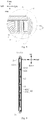
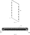
Fig. 1 illustrates an exploded view of an electronic device according to embodiments of the present disclosure. -
Fig. 2 illustrates an enlarged view of portion A1 circled inFig. 1 . -
Fig. 3 illustrates another exploded view of an electronic device according to embodiments of the present disclosure. -
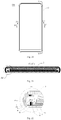
Fig. 4 illustrates a front view of an electronic device according to embodiments of the present disclosure, wherein a protective member is in an initial position. -
Fig. 5 illustrates a sectional view taken along line C1-C1 inFig. 4 . -
Fig. 6 illustrates an enlarged view of portion A2 circled inFig. 5 . -
Fig. 7 illustrates a sectional view taken along line X1-X1 inFig. 4 . -
Fig. 8 illustrates an enlarged view of portion A3 circled inFig. 7 . -
Fig. 9 illustrates a sectional view taken along line Y1-Y1 inFig. 4 . -
Fig. 10 illustrates a side view of the electronic device inFig. 3 . -
Fig. 11 illustrates a sectional view taken along line Z1-Z1 inFig. 10 . -
Fig. 12 illustrates another front view of an electronic device according to embodiments of the present disclosure, wherein a protective member is in a first position. -
Fig. 13 illustrates a sectional view taken along line C2-C2 inFig. 12 . -
Fig. 14 illustrates an enlarged view of portion X4 circled inFig. 13 . -
Fig. 15 illustrates a sectional view taken along line X2-X2 inFig. 12 . -
Fig. 16 illustrates an enlarged view of portion A5 circled inFig. 15 . -
Fig. 17 illustrates a sectional view taken along line Y2-Y2 inFig. 12 . -
Fig. 18 illustrates a side view of the electronic device inFig. 12 . -
Fig. 19 illustrates a sectional view taken along line Z2-Z2 inFig. 18 . -
Fig. 20 illustrates still another front view of an electronic device according to embodiments of the present disclosure, wherein a protective member is in a second position. -
Fig. 21 illustrates a sectional view taken along line C3-C3 inFig. 20 . -
Fig. 22 illustrates an enlarged view of portion A6 circled inFig. 21 . -
Fig. 23 illustrates a sectional view taken along line X3-X3 inFig. 20 . -
Fig. 24 illustrates an enlarged view of portion A7 circled inFig. 23 . -
Fig. 25 illustrates a sectional view taken along line Y3-Y3 inFig. 20 . -
Fig. 26 illustrates a side view of the electronic device inFig. 20 . -
Fig. 27 illustrates a sectional view taken along line Z2-Z2 inFig. 26 . -
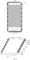
Fig. 28 illustrates a perspective view of a middle frame of an electronic device according to embodiments of the present disclosure. -
Fig. 29 illustrates an exploded view of the middle frame inFig. 28 . -
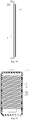
Fig. 30 illustrates a perspective view of a protective member according to embodiments of the present disclosure. -
Fig. 31 illustrates a perspective view of a rear cover according to embodiments of the present disclosure. -
Fig. 32 illustrates a sectional view of an electronic device according to another embodiment of the present disclosure. -
Fig. 33 illustrates an enlarged view of portion A8 circled inFig. 32 . -
Fig. 34 illustrates a sectional view of an electronic device according to still another embodiment of the present disclosure. -
Fig. 35 illustrates an enlarged view of portion A9 circled inFig. 34 . - Reference numerals:
-
electronic device 100, -
rear cover 11,middle frame 12,mounting groove 121,first movement space 1211,second movement space 1212, limitinggroove 13, -
display assembly 2,protective member 3,fitting groove 31, limitingprotrusion 32, -
first magnet 41,mounting hole 411,second magnet 42,driving member 43, mountingpost 430,elastic arm 431, snappinghead 432,first sealing member 5, second sealing member 6,body portion 61,bent portion 62. - Embodiments of the present disclosure will be described in detail below, and examples of the embodiments will be illustrated in the accompanying drawings. The same or similar reference numerals represent the same or similar elements or the elements having the same or similar functions throughout the descriptions. The embodiments described below with reference to the accompanying drawings are exemplary, are merely used to explain the present disclosure, and cannot be construed to limit the present disclosure.
- In the description of the present disclosure, it should be understood that terms such as "central," "longitudinal", "transverse," "length," "width," "thickness," "up," "down," "front," "rear," "left," "right," "vertical," "horizontal," "top," "bottom," "inner," "outer," "clockwise," "counterclockwise," "axial," "radial," "circumferential" and the like should be construed to refer to the orientation as then described or as shown in the drawings under discussion. These terms are for convenience and simplification of description and do not indicate or imply that the device or element referred to must have a particular orientation, or be constructed and operated in a particular orientation, so these terms shall not be construed to limit the present disclosure. In addition, the feature defined with "first" and "second" may comprise one or more of this feature.
- In the present disclosure, it should be noted, unless specified or limited otherwise, the terms "mounted," "connected," "coupled" or the like are used broadly. The terms may be, for example, fixed connections, detachable connections, or integral connections; may also be mechanical or electrical connections, may also be direct connections or indirect connections via intervening structures; and may also be inner communications of two elements, which can be understood by those skilled in the art according to specific situations.
- As illustrated in
Figs. 1-4 , anelectronic device 100 according to one embodiment of the present disclosure includes amiddle frame 12, adisplay assembly 2, arear cover 11 and aprotective member 3. Theelectronic device 100 may be a terminal, such as a mobile phone, a tablet computer, and the like. - Specifically, referring to
Fig. 3 and in combination withFigs. 28 and29 , themiddle frame 12 includes a sidewall arranged in an encircled manner. For example, themiddle frame 12 can be formed into a rectangular frame structure. Thedisplay assembly 2 is located at a front side of themiddle frame 12 and therear cover 11 is located at a rear side of the middle frame. Referring toFig. 1 andFig. 3 and in combination withFig. 31 , therear cover 11 can be formed into a substantially rectangular plate-shaped structure. Optionally, therear cover 11 can be a glass member or a ceramic member. That is, therear cover 11 can be made of glass or ceramic. Thus, the appearance of theelectronic device 100 and the hand feeling of theelectronic device 100 during use can be improved. - The
display assembly 2 can be used to display relevant information of the electronic device 100 (such as a menu and an interface of relevant applications). Thedisplay assembly 2 can also be used as an input apparatus, by which the user can input relevant control information to theelectronic device 100. In one embodiment of the present disclosure, thedisplay assembly 2 can be a touch display screen. - The
protective member 3 can be movably arranged to the sidewall of themiddle frame 11, and in an initial state, a front end and a rear end of theprotective member 3 are lower than or flush with an outer surface of thedisplay assembly 2 and an outer surface of therear cover 11, respectively. Theprotective member 3 can move towards the rear side of themiddle frame 12 from the initial state, such that the rear end of theprotective member 3 exceeds the outer surface of the rear cover, thereby protecting therear cover 11 when theelectronic device 100 drops. - Specifically, in the initial state, the front end of the
protective member 3 is lower than or flush with the outer surface of the display assembly 2 (for example, a front surface inFig. 1 ) and the rear end of theprotective member 3 is lower than or flush with the outer surface of the rear cover 11 (for example, a rear surface inFig. 1 ). Thus, when in use, the overall appearance of theelectronic device 100 can be effectively improved, avoiding that theprotective member 3 affects the appearance of theelectronic device 100, and meanwhile the hand feeling of theelectronic device 100 can be effectively improved. - When the rear end of the
protective member 3 exceeds the outer surface of therear cover 11 by moving theprotective member 3 towards the rear side of themiddle frame 12 from the initial state, an outer periphery of the outer surface of therear cover 11 is wrapped by the protective member 3 (as illustrated inFigs. 19-26 ). For example, theprotective member 3 can be pivoted towards or translated towards the rear side of themiddle frame 12 such that the rear end of theprotective member 3 exceeds the outer surface of therear cover 11. Thus, when theelectronic device 100 drops, theprotective member 3 absorbs the impact of a face, onto which the electronic device drops, on theelectronic device 100 to act as a buffer and protect therear cover 11, so as to effectively prevent therear cover 11 from being damaged due to fall, thereby protecting theelectronic device 100 and improving the anti-dropping performance of theelectronic device 100. - For example, when in use, the
protective member 3 can be adjusted into the initial state to improve the aesthetics of the appearance and the hand feeling of theelectronic device 100. When theelectronic device 100 is not in use or drops, theprotective members 3 can move towards the rear side of themiddle frame 12 such that the rear end of theprotective member 3 exceeds the outer surface of therear cover 11, so as to protect therear cover 11 when theelectronic device 100 drops. - Here, it should be noted that an "outer" direction in the present disclosure refers to a direction adjacent to the center of the
electronic device 100. Accordingly, an "outer" direction in the present disclosure refers to a direction away from the center of theelectronic device 100. - In the
electronic device 100 according to the present disclosure, with the arrangement of theprotective member 3, the front end and the rear end of theprotective member 3 are lower than or flush with the outer surfaces of thedisplay assembly 2 and therear cover 11 when in the initial state, and meanwhile, theprotective member 3 can move from the initial state towards the rear side of themiddle frame 12 to allow the rear end of theprotective member 3 to exceed the outer surface of therear cover 11. Thus, when in use, theprotective member 3 can be adjusted to the initial state to improve the aesthetics of the appearance and the hand feeling of theelectronic device 100. When theelectronic device 100 is not in use or drops, theprotective member 3 can be moved towards the rear side of themiddle frame 12 such that the rear end of theprotective member 3 exceeds the outer surface of therear cover 11, so as to protect therear cover 11 when theelectronic device 100 drops, thereby improving the anti-dropping performance of theelectronic device 100 on the premise of ensuring the aesthetics of the appearance and the hand feeling of theelectronic device 100. Theelectronic device 100 has a simple structure and low production cost, hence improving the cost-performance ratio of theelectronic device 100. - It could be understood that, in one embodiment, the
electronic device 100 may be a mobile phone with a double-sided screen, that is, theelectronic device 100 includes another display assembly arranged facing away from thedisplay assembly 2, besides thedisplay assembly 2. The other display assembly is provided at the rear side of themiddle frame 12 and covered by therear cover 11. In the present embodiment, therear cover 11 may be a cover plate for the other display assembly. When theelectronic device 100 is not in use or drops, theprotective member 3 can be moved towards the rear side of themiddle frame 12 such that the rear end of theprotective member 3 exceeds the outer surface of therear cover 11, so as to protect therear cover 11 and the other display assembly when theelectronic device 100 drops. - According to some embodiments of the present disclosure, the
protective member 3 can move towards the front side of themiddle frame 12 such that the front end of theprotective member 13 exceeds the outer surface of thedisplay assembly 2, so as to protect thedisplay assembly 2 when theelectronic device 100 drops. For example, the protective member can be pivoted towards or translated towards the front side of themiddle frame 12 such that the front end of theprotective member 3 exceeds the outer surface of thedisplay assembly 2. Specifically, when theelectronic device 100 is not in use or drops, theprotective member 3 can be moved towards the front side of themiddle frame 12 such that an outer periphery of the outer surface of thedisplay assembly 12 is wrapped by the protective member 3 (as illustrated inFigs. 12-18 ). Thus, with the protection of theprotective member 3 to thedisplay assembly 2, thedisplay assembly 2 can be prevented from being damaged when theelectronic device 100 drops. - According to some further embodiments of the present disclosure, the
electronic device 100 also includes a driving assembly arranged at themiddle frame 12. The driving assembly is configured to drive theprotective member 3 to move to the rear side of themiddle frame 12 such that the rear end of theprotective member 3 exceeds the outer surface of therear cover 11, or to drive theprotective member 3 to move towards the front side of themiddle frame 12 such that the front end of theprotective member 3 exceeds the outer surface of thedisplay assembly 2, or to drive theprotective member 3 to be restored to the initial state. - For example, when the
display assembly 2 falls towards a face (such as ground, desktop and the like), onto which the electronic device drops, theprotective member 3 can be driven to move towards the front side of themiddle frame 12 by the driving assembly such that the front end of theprotective member 3 exceeds the outer surface of thedisplay assembly 2, and the outer periphery of the outer surface of thedisplay assembly 2 is wrapped by theprotective member 3, so as to protect thedisplay assembly 2 by theprotective member 3 and prevent thedisplay assembly 2 from being damaged when theelectronic device 100 drops. When therear cover 11 falls towards the face, theprotective member 3 can be driven to move towards the rear side of themiddle frame 12 by the driving assembly such that the rear end of theprotective member 3 exceeds the outer surface of therear cover 11 and the outer periphery of the outer surface of therear cover 11 is wrapped by theprotective member 3, so as to protect therear cover 11 by theprotective member 3, thereby preventing therear cover 11 from being damaged when theelectronic device 100 drops. Thus, during the fall of theelectronic device 100, whether thedisplay assembly 2 is falling towards the face or therear cover 11 is falling towards the face, theprotective member 3 can be first brought into contact with the face, and absorb the impact of the face on theelectronic device 100 to play a buffering role, thereby effectively avoiding the damage of thedisplay assembly 2 and therear cover 11 due to the fall, further protecting theelectronic device 100 and improving the anti-dropping performance of theelectronic device 100. - For example, in some specific embodiments of the present disclosure, the
electronic device 100 can be provided with a sensor configured to sense a dropping state of theelectronic device 100, and the sensor is coupled with the driving assembly. Specifically, when theelectronic device 100 drops, the sensor can sense whether a surface of theelectronic device 100 facing towards the face is thedisplay assembly 2 or therear cover 11, and the driving assembly drives theprotective member 3 to move according to a sensing result of the sensor, so as to protect thedisplay assembly 2 and therear cover 11 by theprotective member 3. - According to some embodiments of the present disclosure, the driving assembly includes a driving
member 43, afirst magnet 41, and at least onesecond magnet 42. One end of the drivingmember 43 is coupled with thefirst magnet 41, and the other end of the drivingmember 43 is fitted with theprotective member 3. At least one of the abovesecond magnets 42 is suitable to cooperate with thefirst magnet 41 to urge the drivingmember 43 to drive the protective member to move towards the rear side of themiddle frame 12, such that the rear end of theprotective member 3 exceeds the outer surface of therear cover 11; or at least one of the abovesecond magnets 42 is suitable to cooperate with thefirst magnet 41 to urge the drivingmember 43 to drive theprotective member 3 to move towards the front side of themiddle frame 12, such that the front end of theprotective member 3 exceeds the outer surface of thedisplay assembly 2. - Here, it should be noted that in the description of the present disclosure, the term "a plurality of' means two or more than two, unless specified otherwise.
- For example, referring to
Fig. 29 , thefirst magnet 41 is provided with a mountinghole 411, the drivingmember 43 is provided with a mountingpost 430, and the mountingpost 430 is fitted with the mountinghole 411 to fix thefirst magnet 41 on the drivingmember 43. The structure is simple and the mounting is convenient. - Specifically, one
second magnet 42 or a plurality ofsecond magnets 42 can be provided. Optionally, thesecond magnet 42 can be arranged opposite thefirst magnet 41. In a case of onesecond magnet 42, when theelectronic device 100 drops, the drivingmember 43 can be driven to move through the cooperation between thesecond magnet 42 and thefirst magnet 41, and further the drivingmember 43 drives theprotective member 3 to move to the front side or the rear side of themiddle frame 12, such that the front end of theprotective member 3 exceeds the outer surface of thedisplay assembly 2 or the rear end of theprotective member 3 exceeds the outer surface of therear cover 11. - For example, when the
electronic device 100 drops, a repulsive force or an attractive force can be generated between thesecond magnet 42 and thefirst magnet 41 to urge theprotective member 3 to move to the front side of themiddle frame 12 or the rear side of themiddle frame 12 by the drivingmember 43, such that the front end of theprotective member 3 exceeds the outer surface of thedisplay assembly 2 or the rear end of theprotective member 3 exceeds the outer surface of therear cover 11. - In a case of a plurality of
second magnets 42, when theelectronic device 100 drops, at least one of the plurality ofsecond magnets 42 cooperates with thefirst magnet 41 to urge theprotective member 3 to move to the front side of themiddle frame 12 or the rear side of themiddle frame 12 by means of the drivingmember 43, such that the front end of theprotective member 3 exceeds the outer surface of thedisplay assembly 2 or the rear end of theprotective member 3 exceeds the outer surface of therear cover 11. - For example, in some examples of the present disclosure, there is one
second magnet 42 and thesecond magnet 42 is arranged at a front side of thefirst magnet 41. Referring toFig. 32 and in combination withFig. 33 , thesecond magnet 42 is arranged adjacent to thedisplay assembly 2. In the present embodiment, when thedisplay assembly 2 is falling towards the face during the fall of theelectronic device 100, an attractive force can be generated between thefirst magnet 41 and thesecond magnet 42 to urge thefirst magnet 41 to move towards a direction close to thesecond magnet 42, so that theprotective member 3 can be driven to move to the front side of themiddle frame 12 by the drivingmember 43, and hence the front end of theprotective member 3 exceeds the outer surface of thedisplay assembly 2. With the protection of theprotective member 3 to thedisplay assembly 2, thedisplay assembly 2 is prevented from being damaged when theelectronic device 100 drops. - When the
rear cover 11 is falling towards the face during the fall of theelectronic device 100, a repulsive force can be generated between thefirst magnet 41 and thesecond magnet 42 to move thefirst magnet 41 towards a direction away from thesecond magnet 42, so as to drive theprotective member 3 to move to the rear side of themiddle frame 12 by the drivingmember 43, such that the rear end of theprotective member 3 exceeds the outer surface of therear cover 11. With the protection of theprotective member 3 to therear cover 11, therear cover 11 is prevented from being damaged when theelectronic device 100 drops. - In some other examples of the present disclosure, one
second magnet 42 is provided and arranged at a rear side of thefirst magnet 41. Referring toFig. 34 and in combination withFig. 35 , thesecond magnet 42 is arranged adjacent to therear cover 11. In the present embodiment, during the fall of theelectronic device 100, when thedisplay assembly 2 is falling towards the face, a repulsive force can be generated between thefirst magnet 41 and thesecond magnet 42 to move thefirst magnet 41 towards the direction away from thesecond magnet 42, so as to drive theprotective member 3 to move to the front side of themiddle frame 12 by the drivingmember 43, such that the front end of theprotective member 3 exceeds the outer surface of thedisplay assembly 2. With the protection of theprotective member 3 to thedisplay assembly 2, thedisplay assembly 2 is prevented from being damaged when theelectronic device 100 drops. When therear cover 11 is falling towards the face during the fall of theelectronic device 100, an attractive force can be generated between thefirst magnet 41 and thesecond magnet 42 to move thefirst magnet 41 towards the direction close to thesecond magnet 42, so as to drive theprotective member 3 to move to the rear side of themiddle frame 12 by the drivingmember 43, such that the rear end of theprotective member 3 exceeds the outer surface of therear cover 11. With the protection of theprotective member 3 to therear cover 11, the rear cover is prevented from being damaged when theelectronic device 100 drops. - In some further examples of the present disclosure, two
second magnets 42 are provided, and the twosecond magnets 42 are arranged on opposite sides of thefirst magnet 41 respectively. For example, referring toFig. 21 and in combination withFig. 22 , the twosecond magnets 42 are arranged on the front and rear sides of thefirst magnet 41 respectively, thesecond magnet 42 located at the front side of thefirst magnet 41 is arranged adjacent to thedisplay assembly 2, and thesecond magnet 42 located at the rear side of thefirst magnet 41 is arranged adjacent to therear cover 11. - Specifically, directions of the forces generated between the two
second magnets 42 and thefirst magnet 41 are consistent. For the convenience of description, thesecond magnet 42 located at the front side of thefirst magnet 41 is called as a "front second magnet," and thesecond magnet 42 located at the rear side of thefirst magnet 41 is called as a "rear second magnet." The front second magnet can be coupled with thedisplay assembly 2, and the rear second magnet can be coupled with therear cover 11. Thus, the positions of the front second magnet and the rear second magnet can be stabilized. - For example, in the present embodiment, when the
display assembly 2 is falling towards the face during the fall of theelectronic device 100, an attractive force can be generated between thefirst magnet 41 and the front second magnet, and at the same time a repulsive force can be generated between thefirst magnet 41 and the rear second magnet, to move thefirst magnet 41 towards a direction close to the front second magnet, so as to drive theprotective member 3 to move to the front side of themiddle frame 12 by the drivingmember 43, such that the front end of theprotective member 3 exceeds the outer surface of thedisplay assembly 2. With the protection of theprotective member 3 to thedisplay assembly 2, thedisplay assembly 2 is prevented from being damaged when theelectronic device 100 drops. When therear cover 11 is falling towards the face during the fall of theelectronic device 100, a repulsive force can be generated between thefirst magnet 41 and the front second magnet, and at the same time an attractive force can be generated between thefirst magnet 41 and the rearsecond magnet 42, to move thefirst magnet 41 towards a direction away from the rear second magnet, so as to drive the protective member to move to the rear side of themiddle frame 12 by the drivingmember 43, such that the rear end of theprotective member 3 exceeds the outer surface of therear cover 11. With the protection of theprotective member 3 to therear cover 11, therear cover 11 is prevented from being damaged when theelectronic device 100 drops. - Optionally, the
first magnet 41 is a permanent magnet and thesecond magnet 42 is an electromagnet. Thus, when theelectronic device 100 drops, a coil of the electromagnet can be powered on to generate an attractive force or a repulsive force between thefirst magnet 41 and thesecond magnet 42, such that the movement of theprotective member 3 can be realized by the cooperation of thefirst magnet 41 and thesecond magnet 42 to protect theelectronic device 100. - It could be understood that in some other embodiments of the present disclosure, the
first magnet 41 and thesecond magnet 42 may be both permanent magnets. In some further embodiments of the present disclosure, thefirst magnet 41 is an electromagnet, and thesecond magnet 42 is a permanent magnet. Thus, the movement of theprotective member 3 can also be realized by the cooperation of thefirst magnet 41 and thesecond magnet 42 to protect theelectronic device 100. - According to some further embodiments of the present disclosure, the
electronic device 100 further includes: a sensor and a controller. The sensor is configured to sense a dropping state of theelectronic device 100, and the controller is coupled with the at least onesecond magnet 42 and the sensor. When the sensor senses the fall of theelectronic device 100, the controller is configured to control the at least onesecond magnet 42 to be powered on, to drive theprotective member 3 to move to a first protection position or a second protection position by the drivingmember 43, and when the sensor senses the standstill of theelectronic device 100, the controller is configured to control the at least onesecond magnet 42 to be powered off. - For example, the sensor can sense whether the
electronic device 100 is in the dropping state, and whether the surface towards the face is thedisplay assembly 2 or therear cover 11 during the fall of theelectronic device 100. After the sensor transmits a detection signal to the controller, the power on and power off of thesecond magnet 42 are controlled by the controller to control the position of theprotective member 3. - Optionally, the sensor is at least one of a gyroscope, an acceleration sensor, a gravity sensor, an inertia sensor, a camera, a height sensor, and a motion sensor. That is, the sensor may be one or more of the gyroscope, the acceleration sensor, the gravity sensor, the inertial sensor, the camera, the height sensor, and the motion sensor. For example, in one specific embodiment of the present disclosure, the sensors are the gyroscope and the gravity sensor. Thus, the dropping state of the
electronic device 100 can be detected sensitively and accurately, and the reliability of the sensors can be ensured, which can further ensure the reliability of theelectronic device 100. - Specifically, the
protective member 3 is formed with afitting groove 31, and the other end of the drivingmember 43 mentioned-above is inserted into thefitting groove 31 to be fitted with theprotective member 3. For example, referring toFigs. 1 ,3 ,5-6 ,13-14 ,19 ,21-22 , and30 , thefitting groove 31 is defined in a sidewall of theprotective member 3, which is thus convenient for the above end of the drivingmember 43 to be fitted with theprotective member 3. - In some embodiments of the present disclosure, the
middle frame 12 is formed with a mountinggroove 121, and the drivingmember 43 is arranged in the mountinggroove 121. The drivingmember 43 is configured to be elastically deformable in a moving direction of theprotective member 3 to normally drive theprotective member 3 towards an accommodated position. - For example, when the
display assembly 2 is falling towards the face during the fall of theelectronic device 100, the drivingmember 43 is elastically deformed under the action of thefirst magnet 41 and thesecond magnet 42 and moves towards a direction close to thedisplay assembly 2, and then further drives theprotective member 3 to move to the front side of themiddle frame 12, such that the front end of theprotective member 3 exceeds the outer surface of thedisplay assembly 2. When theelectronic device 100 lands, the acting force between thefirst magnet 41 and thesecond magnet 42 disappears, and the force applied on the drivingmember 43 and causing its elastic deformation disappears. The drivingmember 43 is restored to a natural state under the action of its elastic force and drives theprotective member 3 to move from the front side of themiddle frame 12 to the initial state. - When the
rear cover 11 is falling towards the face during the fall of theelectronic device 100, the drivingmember 43 is elastically deformed under the action of thefirst magnet 41 and thesecond magnet 42 and moves towards a direction close to therear cover 11, and then further drives theprotective member 3 to move to the rear side of themiddle frame 12, such that the rear end of theprotective member 3 exceeds the outer surface of therear cover 11. When theelectronic device 100 lands, the acting force between thefirst magnet 41 and thesecond magnet 42 disappears, and the force applied on the drivingmember 43 and causing its elastic deformation disappears. The drivingmember 43 is restored to a natural state under the action of its elastic force and drives theprotective member 3 to move from the rear side of themiddle frame 12 to the initial state. - Therefore, after the
electronic device 100 lands, theprotective member 3 can be driven from the front or rear side of themiddle frame 12 to the initial state by the drivingmember 43. The driving method is simple, reliable and greatly simplifies the structure of theelectronic device 100, thereby reducing the number of parts of theelectronic device 100 and the cost of theelectronic device 100, and improving the cost-performance ratio of theelectronic device 100. - Specifically, the driving
member 43 includes anelastic arm 431 and a snappinghead 432. Theelastic arm 431 is arranged in the mountinggroove 121. Afirst movement space 1211 is defined between a side surface of theelastic arm 431 adjacent to thedisplay assembly 2 and an inner wall of the mountinggroove 121 opposite to theelastic arm 431. Asecond movement space 1212 is defined between a side surface of theelastic arm 431 away from thedisplay assembly 2 and an inner wall of the mountinggroove 121 opposite to theelastic arm 431. - Specifically, in some examples of the present disclosure, for example, referring to
Figs. 2 ,3 and29 , the mountinggroove 121 is formed in the sidewall of themiddle frame 12. The mountinggroove 121 can be formed as a through groove penetrating along a thickness direction of the sidewall of themiddle frame 12. Theelastic arm 431 can be formed as a long strip. Thefirst movement space 1211 is defined between a front surface of theelastic arm 431 and an inner wall of the mountinggroove 121 opposite to theelastic arm 431, and thesecond movement space 1212 is defined between a rear surface of theelastic arm 431 and an inner wall of the mountinggroove 121 opposite to theelastic arm 431. Thus, theelastic arm 431 is easy to be elastically deformed, the structure is simple, and the processing is convenient. - The snapping
head 432 is arranged on theelastic arm 431 and is suitable to be inserted into thefitting groove 31 to be fitted with theprotective member 3. Specifically, the snappinghead 432 can be arranged on a side of theelastic arm 431 away from a center of themiddle frame 12. For example, referring toFig. 5 and in combination withFig. 6 , the snappinghead 432 can be inserted into thefitting groove 32 to be snapped with thefitting groove 31. Thus, theprotective member 3 can be firmly coupled to themiddle frame 12 by the drivingmember 43. When the drivingmember 43 is elastically deformed, theprotective member 3 can be driven by the fitting of the inner wall of thefitting groove 31 and the snappinghead 432. - Furthermore, the
elastic arm 431 is movable in a direction close to and away from the center of themiddle frame 12, such that the snappinghead 432 is movable between a first position where the snappinghead 432 is fitted with thefitting groove 31 and a second position where the snappinghead 432 is separated from thefitting groove 31. Thus, the mounting and dismounting of the protective assembly can be facilitated, reducing the mounting and dismounting difficulty and improving the mounting and dismounting efficiency of theprotective assembly 3. - For example, in some embodiments of the present disclosure, the
elastic arm 431 can be arranged in the mountinggroove 121 and elastically deformable in a direction close to and away from the center of the middle frame 12 (for example, a left-right direction inFig. 2 ). Thus, the elastic deformation of theelastic arm 431 can move the snappinghead 432 between the first position where the snappinghead 432 is fitted with thefitting groove 31 and the second position where the snappinghead 432 is separated from thefitting groove 31, further simplifying the structure of themiddle frame 12, reducing the number of parts of themiddle frame 12, and lowering the overall cost of theelectronic device 100. - For example, in the process of mounting the
protective member 3, an inner wall of theprotective member 3 can press the snappinghead 432 to allow theelastic arm 431 to be elastically deformed towards the direction close to the center of themiddle frame 12. When thefitting groove 31 is aligned with the mountinggroove 121, theelastic arm 431 can move towards the direction away from the center of themiddle frame 12 to restore the deformation, so as to urge the snappinghead 432 to move towards a direction close to thefitting groove 31 such that the snappinghead 432 is inserted into thefitting groove 31 to be fitted thefitting groove 31. In the process of dismounting theprotective member 3, the snappinghead 432 can be pressed in the direction close to the center of themiddle frame 12, such that the snappinghead 432 is separated from thefitting groove 32, and hence theprotective member 3 can be detached from themiddle frame 12 conveniently. - Optionally, the driving
member 43 is integrally arranged on themiddle frame 12. Specifically, the drivingmember 43 can be integrally arranged on themiddle frame 12 of themiddle frame 12. Thus, the processing technic of themiddle frame 12 can be simplified, the processing cost can be reduced, and the overall structural strength of the drivingmember 43 can be improved. - For example, in some embodiments of the present disclosure, the driving
member 43 can be integrally formed with themiddle frame 12. For another example, in other embodiments of the present disclosure, the drivingmember 43 can also be formed by a cutting process in which case themiddle frame 12 can be processed first, and then the drivingmember 43 can be formed on themiddle frame 12 by the cutting process. - Furthermore, the
electronic device 100 further includes afirst sealing member 5 arranged inside themiddle frame 12 to seal the mountinggroove 121. Specifically, referring toFig. 3 and in combination withFigs. 5 and 6 , thefirst sealing member 5 can be arranged on the sidewall of themiddle frame 12 and adjacent to the center of themiddle frame 12. Thus, the mountinggroove 121 can be sealed by thefirst sealing member 5 to prevent dust, liquid, and the like from entering themiddle frame 12, thus improving the waterproof and dustproof performance of themiddle frame 12, so as to enhance the reliability of theelectronic device 100. - According to some embodiments of the present disclosure, the
protective member 3 is formed in a closed-loop shape and is located outside thedisplay assembly 2. The annularprotective member 3 can wrap all the outer edges of thedisplay assembly 2 and therear cover 11, so as to improve the reliability of the protection for thedisplay assembly 2 and therear cover 11. A plurality of driving assemblies are provided, and the plurality of driving assemblies are spaced apart from each other along a circumferential direction of thedisplay assembly 2. Thus, the plurality of driving assemblies can collectively drive the movement of theprotective member 3, improving the smoothness of the movement of theprotective member 3. - According to some further embodiments of the present disclosure, one of the
middle frame 12 and theprotective member 3 is provided with a plurality of limitinggrooves 13 spaced apart from each other, and the other one of themiddle frame 12 and theprotective member 3 is provided with a plurality of limitingprotrusions 32 fitted with the limitinggrooves 13. That is, when themiddle frame 12 is provided with the limitinggrooves 13, theprotective member 3 is provided with the limitingprotrusions 32 fitted with the limitinggrooves 13; when themiddle frame 12 is provided with the limitingprotrusions 32, theprotective member 3 is provided with the limitinggrooves 13 fitted with the limitingprotrusions 32. - For example, referring to
Figs. 1 ,7 ,8 and11 , themiddle frame 12 is provided with a plurality of limitinggrooves 13 spaced along a circumferential direction thereof, the inner wall of theprotective member 3 is provided with a plurality of limitingprotrusions 32 spaced along a circumferential direction thereof, and the plurality of limitinggrooves 13 are in one-to-one correspondence to the plurality of limitingprotrusions 32. Optionally, an outer peripheral surface of the limitingprotrusion 32 is substantially formed in a cylindrical shape, and an outer contour of the limitinggroove 13 is formed in a rectangular shape. The fitting between the limitingprotrusions 32 and the limitinggrooves 13 can limit the movement of theprotective member 3 in a length direction thereof (for example, an up-down direction inFig. 1 ). Thus, theprotective member 3 can be limited and fixed, which improves the reliability of the connection between theprotective member 3 and themiddle frame 12. - Furthermore, the
electronic device 100 also includes a second sealing member 6 provided between thedisplay assembly 2 and themiddle frame 12, thereby improving the sealing performance of theelectronic device 100, and preventing dust, liquid, and the like from entering the interior of theelectronic device 100, which may otherwise affect the operation of theelectronic device 100 or even cause damage to theelectronic device 100. - As illustrated in
Figs. 5 and 6 , the second sealing member 6 includes abody portion 61 and abent portion 62, and thebent portion 62 is arranged at a circumferential edge of thebody portion 61. Thebody portion 61 is coupled with an inner surface of thedisplay assembly 2, and thebent portion 62 is located between theprotective member 3 and thedisplay assembly 2. Optionally, the second sealing member 6 can be sealedly coupled with thedisplay assembly 2 by dispensing. Thus, the sealing effect of the second sealing member 6 can be improved. - An electronic device according to another embodiment of the present disclosure will be described below, wherein the same components are the same as the same component as above-mentioned embodiments.
- The electronic device according to the embodiment of the present disclosure includes a
middle frame 12, adisplay assembly 2, arear cover 11, aprotective member 3 and a driving assembly. - Specifically, referring to
Fig. 3 and in combination withFigs. 28 and29 , themiddle frame 12 includes a sidewall arranged in an encircled manner. For example, themiddle frame 12 can be formed into a rectangular frame structure. Thedisplay assembly 2 is located at a front side of themiddle frame 12 and therear cover 11 is located at a rear side of themiddle frame 12. Referring toFig. 1 andFig. 3 and in combination withFig. 31 , therear cover 11 can be formed into a substantially rectangular plate-shaped structure. Optionally, therear cover 11 can be a glass member or a ceramic member. That is, therear cover 11 can be made of glass or ceramic. Thus, the appearance of theelectronic device 100 and the hand feeling of theelectronic device 100 can be improved. - The
protective member 3 is arranged on the sidewall of themiddle frame 12. Theprotective member 3 has three position states: in an initial position, a front end of theprotective member 3 is lower than or flush with a surface of thedisplay assembly 2; in a first position, the front end of theprotective member 3 exceeds the surface of thedisplay assembly 2; in a second position, a rear end of theprotective member 3 exceeds a surface of therear cover 11. - For example, the
protective member 3 can be arranged to themiddle frame 12 and be movable among the initial position, the first position and the second position. In the first position, theprotective member 3 moves such that the front end of theprotective member 3 exceeds the outer surface of thedisplay assembly 2. In the second position, theprotective member 3 moves such that the rear end of theprotective member 3 exceeds the outer surface of therear cover 11. In the initial position, the front end of theprotective member 3 is flush with or lower than the outer surface of thedisplay assembly 2, and the rear end of theprotective member 3 is flush with or lower than the outer surface of therear cover 11. - Specifically, in the first position, the front end of the
protective member 3 exceeds the outer surface of thedisplay assembly 2, such that an outer periphery of the outer surface of thedisplay assembly 2 is wrapped by the protective member 3 (as illustrated inFigs. 12-18 ). Thus, with the protection of theprotective member 3 to thedisplay assembly 2, thedisplay assembly 2 can be prevented from being damaged when theelectronic device 100 drops. - In the second position, the rear end of the
protective member 3 exceeds the outer surface of therear cover 11, such that an outer periphery of the outer surface of therear cover 11 is wrapped by the protective member 3 (as illustrated inFigs. 19-26 ). Thus, with the protection of theprotective member 3 to therear cover 11, therear cover 11 can be prevented from being damaged when theelectronic device 100 drops. - In the initial position, the front end of the
protective member 3 is flush with or lower than the outer surface of thedisplay assembly 2, and the rear end of theprotective member 3 is flush with or lower than the outer surface of the rear cover 11 (as illustrated inFig. 10 ). Thus, when theelectronic device 100 is in a non-dropping state, the overall appearance of theelectronic device 100 can be effectively improved, thus avoiding theprotective member 3 from affecting the aesthetics of the appearance of theelectronic device 100. - When the
electronic device 100 is in a non-dropping state, it should be understood as a state when the user normally uses theelectronic device 100, or when theelectronic device 100 is stationary, and the like. - The driving assembly can be arranged in the
middle frame 12, and the driving assembly is configured to drive theprotective member 3 to move from the initial position to the first position, or drive theprotective member 3 to move from the initial position to the second position. - For example, when the
display assembly 2 is falling towards the face, theprotective member 3 can be driven by the driving assembly to move to the first position, such that the outer periphery of the outer surface of thedisplay assembly 2 is wrapped by theprotective member 3. Thus, with the protection of theprotective member 3 to thedisplay assembly 2, thedisplay assembly 2 can be prevented from being damaged when theelectronic device 100 drops. When therear cover 11 is falling towards the face, theprotective member 3 can be driven by the driving assembly to move to the second position, such that the outer periphery of the outer surface of therear cover 11 is wrapped by theprotective member 3. Thus, with the protection of theprotective member 3 to therear cover 11, therear cover 11 can be prevented from being damaged when theelectronic device 100 drops. Therefore, during the fall of theelectronic device 100, whether thedisplay assembly 2 is falling towards the face or therear cover 11 is falling towards the face, theprotective member 3 can be first brought into contact with the face, and absorb the impact of the face on theelectronic device 100 to play a buffering role, thereby effectively avoiding the damage of thedisplay assembly 2 and the rear cover due to the fall, further protecting theelectronic device 100 and improving the anti-dropping performance of theelectronic device 100. - For example, in some specific embodiments of the present disclosure, the
electronic device 100 can be provided with a sensor used to sense a dropping state of theelectronic device 100, and the sensor is coupled with the driving assembly. Specifically, when theelectronic device 100 drops, the sensor can sense whether a surface of theelectronic device 100 facing towards the face is thedisplay assembly 2 or therear cover 11, and the driving assembly drives theprotective member 3 to move according to a sensing result of the sensor, so as to protect thedisplay assembly 2 and therear cover 11 by theprotective member 3. - For the
electronic device 100 according to the embodiment of the present disclosure, by providing theprotective member 3 having three position states, thedisplay assembly 2 and the rear cover can be protected by theprotective member 3 and be prevented from being damaged during the fall of theelectronic device 100, which improves the anti-dropping performance of theelectronic device 100. Meanwhile, when theelectronic device 100 is in a normal state, the aesthetics of theelectronic device 100 can be improved. Moreover, theprotective member 3 has a simple structure and low production cost, hence improving the cost-performance ratio of theelectronic device 100. - According to some specific embodiments of the present disclosure, the driving assembly drives the protective member to move from the first position to the initial position or drives the protective member to move from the second position to the initial position after the electronic device drops. Thus, after the electronic device lands, the protective member can be automatically restored to the initial position, which can effectively improve the overall appearance of the
electronic device 100 and avoid the effect of theprotective member 3 on the aesthetics of the appearance of theelectronic device 100. - It should be understood that the structure and working principle of the driving assembly in the present embodiment can be the same as those of the driving assembly in the above embodiments, which will not be described in detail herein.
- It should be noted that "the
electronic device 100" of the present disclosure includes, but is not limited to devices for receiving/transmitting a communication signal via a wired line connection (for example, via Public Switched Telephone Network (PSTN), Digital Subscriber Line (DSL), a digital cable, direct cable connection, and/or another data connection/network) and/or via a wireless interface (for example, cellular networks, wireless local area networks (WLANs), digital television networks (such as DVB-H networks), satellite networks, AM-FM broadcast transmitters, and/or another communication terminal). Examples of theelectronic device 100 include, but are not limited to, satellite or cellular telephones; personal communication system (PCS) devices that may combine cellular radiotelephone with data processing, fax, and data communication capabilities; PDAs that may include radiotelephones, pagers, Internet/Intranet access, web browsers, memo pads, calendars, and/or global positioning system (GPS) receivers; and conventional laptop and/or palmtop receivers or other electronic devices including radiotelephone transceivers. - The
electronic device 100 can be a device capable of acquiring data from the outside and processing the data, or theelectronic device 100 can be a device including a built-in battery and capable of charging the battery by drawing current from the outside, for example, a mobile phone (the embodiments as illustrated inFigs. 1-35 ), a tablet computer, a computing device or an information display device. The mobile phone is merely an example of theelectronic device 100, which is not specifically limited in the present disclosure. The present disclosure can be applied to mobile phones, tablet computers and otherelectronic devices 100, which is not limited in the present disclosure. - In embodiments of the present disclosure, the mobile phone can include a radio-frequency circuit, a memory, an input unit, a wireless fidelity (Wi-Fi) module, a
display assembly 2, a sensor, an audio circuit, a processor, a fingerprint identification assembly, a battery and the like. - The radio-frequency circuit can be used to receive and transmit a signal during information transmission and reception or during a call. Especially, when downlink information from a base station is received, the radio-frequency circuit sends the downlink information to the processor for processing, and additionally sends uplink data from the mobile phone to the base station. Usually, the radio-frequency circuit includes but is not limited to an antenna, at least one amplifier, a transceiver, a coupler, a low-noise amplifier, a duplexer and etc. In addition, the radio-frequency circuit can communicate with the network and other devices via wireless communication.
- The memory can be used to store software programs and modules, and the processor runs various function applications in the mobile phone and performs data processing by running the software programs and modules stored in the memory. The memory mainly includes a program storage area and a data storage area. The program storage area can store an operating system, at least one application program required for a function (such as a voice playback function, an image playback function and etc.); the data storage area can store data (such as audio data, contacts and etc.) created according to the use of the mobile phone. In addition, the memory may include a high-speed random access memory, and may also include a non-volatile memory, such as at least one disk storage device, a flash memory device, or other volatile solid-state memory devices.
- The input unit can be configured to receive incoming numbers or character information, and generate a key signal related to user settings and function control of the mobile phone. Specifically, the input unit can include a touch panel and other input devices. The touch panel, also known as a touch screen, can collect a touch operation made by a user on or near the touch panel (for example, an operation made by the user on the touch panel or near the touch panel by means of a finger, a touch pen or any other suitable object or accessory), and drive the corresponding connection device according to a preset program.
- Optionally, the touch panel can include a touch detection device and a touch controller. The touch detection device is configured to detect a touch orientation of the user, detect a signal from the touch operation, and transmit the signal to the touch controller. The touch controller is configured to receive the touch information from the touch detection device, convert it into contact coordinates and send the contact coordinates to the processor, and is also configured to receive and execute a command from the processor. In addition, it is possible to realize the touch panel in resistive type, capacitive type, infrared type, surface acoustic wave type and other types. The input unit may include other input devices apart from the touch panel. Specifically, other input devices may include, but are not limited to one or more of a physical keypad, a function key (e.g. a volume control button, an on/off button, etc.), a trackball, a mouse and an operating rod.
- The
display assembly 2 can include a display panel, and optionally, the display panel can be configured in forms of a liquid crystal display (LCD), an organic light-emitting diode (OLED) and the like. Further, the touch panel can overlay the display panel; when the touch panel detects a touch operation on or near it, the touch operation is sent to the processor to determine which type the touch event belongs to, and then the processor provides a corresponding visual output on the display panel according to the type of the touch event. - The audio circuit, the loudspeaker and the microphone can provide an audio interface between the user and the mobile phone. The audio circuit can transmit an electrical signal converted from the received audio data to the loudspeaker, and the loudspeaker converts the electrical signal into an audio signal to be output. On the other hand, the microphone converts the collected audio signal into the electrical signal, and the audio circuit receives and converts the electrical signal into audio data, and transmits the audio data to the processor. After processed by the processor, the audio data is sent to, for example, another mobile phone via the radio-frequency circuit, or is output to the memory for further processing.
- Wi-Fi is a short-distance wireless transmission technology, and the electronic device can help the user to send and receive e-mails, browse websites, and access streaming media by means of the Wi-Fi module which provides the user with wireless broadband access to the Internet. However, it could be understood that the Wi-Fi module is not a necessary component of the mobile phone and can be omitted as needed without changing the nature of the present disclosure.
- The processor is a control center of the electronic device and mounted on a circuit board assembly. The processor is coupled to various parts of the mobile phone by means a variety of interfaces and lines, and performs various functions of the mobile phone and data processing by running or executing software programs and/or modules stored in the memory and by invoking the data stored in the memory, so as to monitor the electronic device overall. Optionally, the processor can include one or more processing units. Preferably, the processor may be integrated with an application processor and a modem processor, in which the application processor mainly handles the operating system, the user interface and the application program, while the modem processor mainly deals with wireless communication.
- The power source can be logically coupled to the processor by means of a power management system, to manage functions such as charging, discharging, and power management by means of the power management system. Although not shown, the electronic device may also include a Bluetooth module, and a sensor (such as an attitude sensor, a light sensor and other sensors like a barometer, a hygrometer, a thermometer and an infrared sensor), which will not be described herein.
- Reference throughout this specification to "an embodiment," "some embodiments," "an illustrative embodiment," "an example", "a specific example," or "some examples," means that a particular feature, structure, material, or characteristic described in connection with the embodiment or example is included in at least one embodiment or example of the present disclosure. Thus, the appearances of the phrases in various places throughout this specification are not necessarily referring to the same embodiment or example of the present disclosure. Moreover, the particular features, structures, materials, or characteristics described may be combined in any suitable manner in one or more embodiments or examples.
- Although embodiments of the present disclosure have been illustrated and described above, it should be understood by those skilled in the art that changes, modifications, alternatives, and variations can be made in the embodiments without departing from principles and purposes of the present disclosure. The scope of this application is limited by the claims and their equivalents.
Claims (20)
- An electronic device, comprising:a middle frame comprising a sidewall arranged in an encircled manner;a display assembly located at a front side of the middle frame;a rear cover located at a rear side of the middle frame; anda protective member movably provided on the sidewall of the middle frame, wherein in an initial state, a front end of the protective member is lower than or flush with an outer surface of the display assembly and a rear end of the protective member is lower than or flush with an outer surface of the rear cover; the protective member is movable towards the rear side of the middle frame from the initial state such that the rear end of the protective member exceeds the outer surface of the rear cover, so as to protect the rear cover when the electronic device drops.
- The electronic device according to claim 1, wherein the protective member is movable towards the front side of the middle frame such that the front end of the protective member exceeds the outer surface of the display assembly, so as to protect the display assembly when the electronic device drops.
- The electronic device according to claim 2, further comprising a driving assembly provided to the middle frame, wherein the driving assembly is configured to drive the protective member to move towards the rear side of the middle frame such that the rear end of the protective member exceeds the outer surface of the rear cover, or drive the protective member to move towards the front side of the middle frame such that the front end of the protective member exceeds the outer surface of the display assembly, or drive the protective member to be restored to the initial state.
- The electronic device according to claim 3, wherein the driving assembly comprises a driving member, a first magnet, and at least one second magnet; the driving member has a first end coupled with the first magnet and a second end fitted with the protective member; the at least one second magnet cooperates with the first magnet to urge the driving member to drive the protective member to move towards the rear side of the middle frame, such that the rear end of the protective member exceeds the outer surface of the rear cover, or the at least one second magnet cooperates with the first magnet to urge the driving member to drive the protective member to move towards the front side of the middle frame, such that the front end of the protective member exceeds the outer surface of the display assembly.
- The electronic device according to claim 4, wherein the first magnet is a permanent magnet, and the second magnet is an electromagnet.
- The electronic device according to claim 5, further comprising:a sensor configured to sense a dropping state of the electronic device; anda controller coupled with the at least one second magnet and the sensor, wherein the controller is configured, when the sensor senses the fall of the electronic device, to control the at least one second magnet to be powered on so as to urge the driving member to drive the protective member to move towards the middle frame such that the rear end of the protective member exceeds the outer surface of the rear cover, or drive the protective member to move towards the front side of the middle frame such that the front end of the protective member exceeds the outer surface of the display assembly, and the controller is configured, when the sensor senses the standstill of the electronic device, to control the at least one second magnet to be powered off.
- The electronic device according to claim 4, wherein the protective member is formed with a fitting groove, and the second end of the driving member is inserted into the fitting groove to be fitted with the protective member.
- The electronic device according to claim 7, wherein the middle frame is formed with a mounting groove, the driving member is arranged in the mounting groove, and the driving member is configured to be elastically deformable in a moving direction of the protective member to normally drive the protective member to be restored to the initial state.
- The electronic device according to claim 8, wherein the driving member comprises:an elastic arm provided in the mounting groove, a first movement space defined between a side surface of the elastic arm adjacent to the display assembly and an inner wall of the mounting groove opposite to the side surface of the elastic arm adjacent to the display assembly, and a second movement space defined between a side surface of the elastic arm away from the display assembly and an inner wall of the mounting groove opposite to the side surface of the elastic arm away from the display assembly; anda snapping head provided on the elastic arm and inserted into the fitting groove to be fitted with the protective member.
- The electronic device according to claim 9, wherein the elastic arm is movable in a direction close to and away from a center of the middle frame, and the snapping head is movable between a first position where the snapping head is fitted with the fitting groove and a second position where the snapping head is separated from the fitting groove.
- The electronic device according to claim 10, wherein the elastic arm is arranged in the mounting groove and is elastically deformable in the direction close to and away from the center of the middle frame.
- The electronic device according to claim 8, wherein the driving member is integrally arranged on the middle frame.
- The electronic device according to claim 8, further comprising a first sealing member provided to the middle frame to seal the mounting groove.
- The electronic device according to claim 3, wherein the protective member is formed in a closed-loop shape and is located outside the display assembly, and a plurality of driving assemblies are provided and spaced apart from each other along a circumferential direction of the display assembly.
- The electronic device according to any one of claims 1 to 14, wherein one of the middle frame and the protective member is provided with a plurality of limiting grooves spaced apart from each other, and the other one of the middle frame and the protective member is provided with a plurality of limiting protrusions fitted with the limiting grooves.
- The electronic device according to any one of claims 1 to 15, further comprising a second sealing member provided between the display assembly and the middle frame.
- The electronic device according to any one of claims 1 to 16, wherein the sensor is configured as at least one of a gyroscope, an acceleration sensor, a gravity sensor, an inertia sensor, a camera, a height sensor, and a motion sensor.
- The electronic device according to any one of claims 1 to 17, wherein the rear cover is a glass member or a ceramic member.
- An electronic device, comprising:a middle frame comprising a sidewall arranged in an encircled manner;a display assembly located at a front side of the middle frame;a rear cover located at a rear side of the middle frame;a protective member provided on the sidewall of the middle frame, wherein the protective member has three position states: an initial position where a front end of the protective member is lower than or flush with an outer surface of the display assembly; a first position where the front end of the protective member exceeds the outer surface of the display assembly; and a second position where a rear end of the protective member exceeds an outer surface of the rear cover; anda driving assembly configured to drive the protective member to move from the initial position to the first position or drive the protective member to move from the initial position to the second position, when the electronic device drops.
- The electronic device according to claim 19, wherein after the electronic device drops, the driving assembly drives the protective member to move from the first position to the initial position or drives the protective member to move from the second position to the initial position.
Applications Claiming Priority (3)
| Application Number | Priority Date | Filing Date | Title |
|---|---|---|---|
| CN201711208567.8A CN107870657A (en) | 2017-11-27 | 2017-11-27 | Electronic installation |
| CN201721619270.6U CN207460300U (en) | 2017-11-27 | 2017-11-27 | Electronic device |
| PCT/CN2018/115898 WO2019101011A1 (en) | 2017-11-27 | 2018-11-16 | Electronic device |
Publications (2)
| Publication Number | Publication Date |
|---|---|
| EP3674835A1 true EP3674835A1 (en) | 2020-07-01 |
| EP3674835A4 EP3674835A4 (en) | 2020-11-18 |
Family
ID=66631320
Family Applications (1)
| Application Number | Title | Priority Date | Filing Date |
|---|---|---|---|
| EP18881273.9A Pending EP3674835A4 (en) | 2017-11-27 | 2018-11-16 | Electronic device |
Country Status (3)
| Country | Link |
|---|---|
| US (1) | US11051412B2 (en) |
| EP (1) | EP3674835A4 (en) |
| WO (1) | WO2019101011A1 (en) |
Families Citing this family (4)
| Publication number | Priority date | Publication date | Assignee | Title |
|---|---|---|---|---|
| US11357121B2 (en) * | 2020-06-24 | 2022-06-07 | Wuhan China Star Optoelectronics Semiconductor Display Technology Co., Ltd. | Foldable display device |
| WO2022004908A1 (en) * | 2020-06-30 | 2022-01-06 | 엘지전자 주식회사 | Flexible display device |
| US11800649B2 (en) * | 2020-08-19 | 2023-10-24 | Apple Inc. | Mobile display encapsulation to improve robustness and water resistance |
| US11889647B2 (en) | 2020-08-19 | 2024-01-30 | Apple Inc. | Display panel bend reinforcement |
Family Cites Families (14)
| Publication number | Priority date | Publication date | Assignee | Title |
|---|---|---|---|---|
| US8330305B2 (en) * | 2010-02-11 | 2012-12-11 | Amazon Technologies, Inc. | Protecting devices from impact damage |
| US8305744B2 (en) * | 2010-05-14 | 2012-11-06 | Apple Inc. | Shock mounting cover glass in consumer electronics devices |
| CN104008705A (en) | 2013-02-26 | 2014-08-27 | 鸿富锦精密工业(深圳)有限公司 | Electronic device |
| US9715257B2 (en) * | 2014-04-18 | 2017-07-25 | Apple Inc. | Active screen protection for electronic device |
| US9612622B2 (en) * | 2014-05-13 | 2017-04-04 | Apple Inc. | Electronic device housing |
| KR102341107B1 (en) * | 2015-08-13 | 2021-12-21 | 삼성전자주식회사 | Electronic device, protecting device of the electronic device and method thereof |
| KR20170043884A (en) * | 2015-10-14 | 2017-04-24 | 삼성전자주식회사 | Electronic device including portective member |
| US10315828B2 (en) * | 2016-06-14 | 2019-06-11 | Apple Inc. | Active surface protection for portable electronic devices |
| US10405440B2 (en) * | 2017-04-10 | 2019-09-03 | Romello Burdoucci | System and method for interactive protection of a mobile electronic device |
| KR20190038648A (en) * | 2016-08-17 | 2019-04-08 | 레이싱 옵틱스 아이엔씨. | Mobile device shock protection |
| CN106555799B (en) | 2017-01-18 | 2018-09-11 | 广东欧珀移动通信有限公司 | The casing assembly and terminal of terminal |
| CN107343073B (en) * | 2017-07-03 | 2020-04-14 | 张景飞 | Anti-falling and anti-collision system |
| CN207460300U (en) | 2017-11-27 | 2018-06-05 | 广东欧珀移动通信有限公司 | Electronic device |
| CN107870657A (en) | 2017-11-27 | 2018-04-03 | 广东欧珀移动通信有限公司 | Electronic installation |
-
2018
- 2018-11-16 EP EP18881273.9A patent/EP3674835A4/en active Pending
- 2018-11-16 WO PCT/CN2018/115898 patent/WO2019101011A1/en unknown
- 2018-11-16 US US16/649,858 patent/US11051412B2/en active Active
Also Published As
| Publication number | Publication date |
|---|---|
| US11051412B2 (en) | 2021-06-29 |
| EP3674835A4 (en) | 2020-11-18 |
| US20200275560A1 (en) | 2020-08-27 |
| WO2019101011A1 (en) | 2019-05-31 |
Similar Documents
| Publication | Publication Date | Title |
|---|---|---|
| US11051412B2 (en) | Electronic device | |
| CN108683757B (en) | Electronic device and electronic apparatus | |
| AU2018373975B2 (en) | Electronic device | |
| US10788860B2 (en) | Display screen component and foldable device having same | |
| CN110661954A (en) | Camera module and terminal equipment | |
| CN108055363B (en) | Electronic device | |
| WO2019101007A1 (en) | Electronic device and control method for display assembly thereof | |
| CN107944308B (en) | Electronic device and fall protection method thereof | |
| CN110995899B (en) | Mobile terminal and control method thereof | |
| CN210015391U (en) | Electronic equipment and center frame | |
| EP3697077A1 (en) | Camera assembly and electronic device having same | |
| CN108023994B (en) | Side key structure and mobile terminal with same | |
| CN209897092U (en) | Electronic device | |
| US10729019B2 (en) | Electronic device | |
| CN110063553B (en) | Wearable device | |
| CN107872551B (en) | Electronic device and fall protection method thereof | |
| CN107959741B (en) | Terminal device | |
| CN108055364B (en) | Electronic device | |
| CN108259647B (en) | Light sensor assembly and electronic device with same | |
| CN108566454B (en) | Middle frame and terminal | |
| CN108055372B (en) | Electronic device | |
| CN108229374B (en) | Fingerprint module, manufacturing method of fingerprint module and electronic device | |
| CN107864258B (en) | Shell assembly of electronic equipment and electronic equipment | |
| CN108111669B (en) | Electronic device and fall protection method thereof | |
| CN212209297U (en) | Terminal device and shell assembly thereof |
Legal Events
| Date | Code | Title | Description |
|---|---|---|---|
| STAA | Information on the status of an ep patent application or granted ep patent |
Free format text: STATUS: THE INTERNATIONAL PUBLICATION HAS BEEN MADE |
|
| PUAI | Public reference made under article 153(3) epc to a published international application that has entered the european phase |
Free format text: ORIGINAL CODE: 0009012 |
|
| STAA | Information on the status of an ep patent application or granted ep patent |
Free format text: STATUS: REQUEST FOR EXAMINATION WAS MADE |
|
| 17P | Request for examination filed |
Effective date: 20200325 |
|
| AK | Designated contracting states |
Kind code of ref document: A1 Designated state(s): AL AT BE BG CH CY CZ DE DK EE ES FI FR GB GR HR HU IE IS IT LI LT LU LV MC MK MT NL NO PL PT RO RS SE SI SK SM TR |
|
| AX | Request for extension of the european patent |
Extension state: BA ME |
|
| A4 | Supplementary search report drawn up and despatched |
Effective date: 20201016 |
|
| RIC1 | Information provided on ipc code assigned before grant |
Ipc: G06F 1/16 20060101AFI20201012BHEP |
|
| DAV | Request for validation of the european patent (deleted) | ||
| DAX | Request for extension of the european patent (deleted) | ||
| STAA | Information on the status of an ep patent application or granted ep patent |
Free format text: STATUS: EXAMINATION IS IN PROGRESS |
|
| 17Q | First examination report despatched |
Effective date: 20220321 |
|
| GRAP | Despatch of communication of intention to grant a patent |
Free format text: ORIGINAL CODE: EPIDOSNIGR1 |
|
| STAA | Information on the status of an ep patent application or granted ep patent |
Free format text: STATUS: GRANT OF PATENT IS INTENDED |
|
| INTG | Intention to grant announced |
Effective date: 20230810 |