EP3674776B1 - Endoskopsystem und integriertes entwurfsverfahren für ein optisches endoskopkamerasystem - Google Patents
Endoskopsystem und integriertes entwurfsverfahren für ein optisches endoskopkamerasystem Download PDFInfo
- Publication number
- EP3674776B1 EP3674776B1 EP17936800.6A EP17936800A EP3674776B1 EP 3674776 B1 EP3674776 B1 EP 3674776B1 EP 17936800 A EP17936800 A EP 17936800A EP 3674776 B1 EP3674776 B1 EP 3674776B1
- Authority
- EP
- European Patent Office
- Prior art keywords
- endoscope
- lens module
- module
- present disclosure
- light path
- Prior art date
- Legal status (The legal status is an assumption and is not a legal conclusion. Google has not performed a legal analysis and makes no representation as to the accuracy of the status listed.)
- Active
Links
Images


Classifications
-
- A—HUMAN NECESSITIES
- A61—MEDICAL OR VETERINARY SCIENCE; HYGIENE
- A61B—DIAGNOSIS; SURGERY; IDENTIFICATION
- A61B1/00—Instruments for performing medical examinations of the interior of cavities or tubes of the body by visual or photographical inspection, e.g. endoscopes; Illuminating arrangements therefor
- A61B1/04—Instruments for performing medical examinations of the interior of cavities or tubes of the body by visual or photographical inspection, e.g. endoscopes; Illuminating arrangements therefor combined with photographic or television appliances
- A61B1/05—Instruments for performing medical examinations of the interior of cavities or tubes of the body by visual or photographical inspection, e.g. endoscopes; Illuminating arrangements therefor combined with photographic or television appliances characterised by the image sensor, e.g. camera, being in the distal end portion
-
- G—PHYSICS
- G02—OPTICS
- G02B—OPTICAL ELEMENTS, SYSTEMS OR APPARATUS
- G02B23/00—Telescopes, e.g. binoculars; Periscopes; Instruments for viewing the inside of hollow bodies; Viewfinders; Optical aiming or sighting devices
- G02B23/24—Instruments or systems for viewing the inside of hollow bodies, e.g. fibrescopes
- G02B23/2476—Non-optical details, e.g. housings, mountings, supports
- G02B23/2484—Arrangements in relation to a camera or imaging device
-
- A—HUMAN NECESSITIES
- A61—MEDICAL OR VETERINARY SCIENCE; HYGIENE
- A61B—DIAGNOSIS; SURGERY; IDENTIFICATION
- A61B1/00—Instruments for performing medical examinations of the interior of cavities or tubes of the body by visual or photographical inspection, e.g. endoscopes; Illuminating arrangements therefor
- A61B1/00002—Operational features of endoscopes
- A61B1/00043—Operational features of endoscopes provided with output arrangements
- A61B1/00045—Display arrangement
-
- A—HUMAN NECESSITIES
- A61—MEDICAL OR VETERINARY SCIENCE; HYGIENE
- A61B—DIAGNOSIS; SURGERY; IDENTIFICATION
- A61B1/00—Instruments for performing medical examinations of the interior of cavities or tubes of the body by visual or photographical inspection, e.g. endoscopes; Illuminating arrangements therefor
- A61B1/00163—Optical arrangements
- A61B1/00174—Optical arrangements characterised by the viewing angles
-
- A—HUMAN NECESSITIES
- A61—MEDICAL OR VETERINARY SCIENCE; HYGIENE
- A61B—DIAGNOSIS; SURGERY; IDENTIFICATION
- A61B1/00—Instruments for performing medical examinations of the interior of cavities or tubes of the body by visual or photographical inspection, e.g. endoscopes; Illuminating arrangements therefor
- A61B1/002—Instruments for performing medical examinations of the interior of cavities or tubes of the body by visual or photographical inspection, e.g. endoscopes; Illuminating arrangements therefor having rod-lens arrangements
-
- A—HUMAN NECESSITIES
- A61—MEDICAL OR VETERINARY SCIENCE; HYGIENE
- A61B—DIAGNOSIS; SURGERY; IDENTIFICATION
- A61B1/00—Instruments for performing medical examinations of the interior of cavities or tubes of the body by visual or photographical inspection, e.g. endoscopes; Illuminating arrangements therefor
- A61B1/04—Instruments for performing medical examinations of the interior of cavities or tubes of the body by visual or photographical inspection, e.g. endoscopes; Illuminating arrangements therefor combined with photographic or television appliances
- A61B1/055—Instruments for performing medical examinations of the interior of cavities or tubes of the body by visual or photographical inspection, e.g. endoscopes; Illuminating arrangements therefor combined with photographic or television appliances having rod-lens arrangements
-
- G—PHYSICS
- G02—OPTICS
- G02B—OPTICAL ELEMENTS, SYSTEMS OR APPARATUS
- G02B23/00—Telescopes, e.g. binoculars; Periscopes; Instruments for viewing the inside of hollow bodies; Viewfinders; Optical aiming or sighting devices
- G02B23/24—Instruments or systems for viewing the inside of hollow bodies, e.g. fibrescopes
- G02B23/2407—Optical details
- G02B23/2423—Optical details of the distal end
- G02B23/243—Objectives for endoscopes
-
- G—PHYSICS
- G02—OPTICS
- G02B—OPTICAL ELEMENTS, SYSTEMS OR APPARATUS
- G02B23/00—Telescopes, e.g. binoculars; Periscopes; Instruments for viewing the inside of hollow bodies; Viewfinders; Optical aiming or sighting devices
- G02B23/24—Instruments or systems for viewing the inside of hollow bodies, e.g. fibrescopes
- G02B23/2407—Optical details
- G02B23/2453—Optical details of the proximal end
Definitions
- the present disclosure relates to an endoscope optical system, and in particular to an integrated endoscope and a design method for an endoscope optical system.
- the endoscopes has been used in more and more widespread manner.
- the existing endoscopes are used almost completely in combination with a camera system.
- the present invention provides an endoscope system as defined in claim 1.
- the endoscope is a rigid endoscope.
- the non-parallel light/divergent light forms a high-definition image on the digital camera after passing through the optical interface light path module.
- an imaging quality of the image formed on the digital ultra-high-definition camera is better than an imaging quality of an image output by the optical interface light path module.
- an imaging quality of the image formed on the digital camera is better than an imaging quality of an image formed on a visual plane of the eye lens module.
- an entrance pupil diameter of the object lens module for products of different specifications is 0.2mm to 1mm.
- an exit pupil diameter of the eye lens module is 3mm-6mm.
- an entrance pupil diameter of the object lens module is 0.2mm to 1mm
- an exit pupil diameter of the eye lens module is 3mm to 6mm.
- the system is used for a spherical or aspherical endoscope.
- the system is used for an endoscope having an appearance diameter of 1.9mm, 2.7mm, 4mm, 5mm, 6mm, 8mm and 10mm.
- a viewing-direction angle of the system may be 0°, 30°, 45°, or 70° or more.
- a distance from the object lens module to the eye lens module in the system may be of any length.
- an integrated design method for an endoscope camera optical system wherein the system includes an object lens module, a relay module, an eye lens module, an optical interface light path module, and a digital ultra-high-definition camera, which are sequentially arranged along a light path direction; a relative aperture of the system is increased by increasing an exit pupil diameter of the eye lens module so that a resolution of an image formed on the digital ultra-high-definition camera is improved.
- the exit pupil diameter of the eye lens module is increased to 3mm-6mm.
- a resolution of the image formed on the digital camera is improved by increasing an entrance pupil diameter of the object lens module.
- the entrance pupil diameter of the object lens module is increased to 0.2mm to 1mm.
- the entrance pupil diameter of the object lens module is increased to 0.2mm-1mm.
- the design method is used for a rigid endoscope.
- the design method is used for a spherical or aspherical endoscope.
- the system is used for an endoscope having an appearance diameter of 1.9mm, 2.7mm, 4mm, 5mm, 6mm, 8mm and 10mm.
- a viewing-direction angle of the system may be 0°, 30°, 45°, or 70° or more.
- a distance from the object lens module to the eye lens module in the system may be of any length.
- an endoscope for the endoscope system as described above is proposed, wherein the endoscope includes the object lens module, the relay module, and the eye lens module.
- an endoscope for the endoscope system as described above is proposed, wherein the endoscope includes the object lens module, the relay module, the eye lens module and the optical interface light path module.
- an optical adaptation interface for the endoscope system as described above is proposed, wherein the optical adaptation interface includes the optical interface light path module.
- the overall relative aperture is increased and the resolution is improved by the present disclosure.
- the overall optimization design of the endoscope system is considered as a whole without taking the image quality of each individual part into consideration.
- the present disclosure proposes a new integrated optical system of an endoscope, which can greatly improve the resolution of the endoscope. Moreover, in some embodiments of the present disclosure, the cost of the endoscope is not significantly increased.
- FIG. 1 is a schematic view of an endoscope optical system according to an embodiment of the present invention.
- the endoscope system 100 includes an object lens module 101, a relay module 102, an eye lens module 103, an optical interface light path module 104, and an imaging device 105.
- the imaging device 105 is a digital ultra-high-definition camera.
- the object lens module 101 may include an entrance pupil 106 and a plurality of lenses for imaging an area to be observed.
- the entrance pupil 106 may be similar to a diaphragm and is configured to restrict light entering the object lens module.
- the relay module 102 includes a plurality of lenses for re-imaging light from an image formed by the object lens module for multiple times, thereby transmitting the image formed by the object lens module.
- the eye lens module 103 includes a plurality of lenses for magnifying an image received from the relay module 102.
- the eye lens module 103 includes an exit pupil 107.
- the optical interface light path module 104 includes a plurality of lenses for re-imaging light from an image formed by the eye lens module 103 onto an imaging surface of the imaging device 105.
- the optical interface light path module 104 is closely adjacent to the eye lens module 103, so the exit pupil 107 of the eye lens module 103 may also be used as an entrance pupil of the optical interface light path module 104.
- the endoscope may include a display 108 for displaying an image from the imaging device 105.
- the optical interface light path module 104 is adapted to the imaging device 105.
- the optical system of the endoscope may include only the object lens module 101, the relay module 102, and the eye lens module 103.
- the designer designs the object lens module 101, the relay module 102, and the eye lens module 103 according to the parameters of the optical interface light path module 104 and the imaging device 105. Therefore, a situation in which the optical system of the endoscope does not include the optical interface light path module 104 and the imaging device 105 also falls within the scope of protection of the present disclosure.
- the optical system of the endoscope may include only the object lens module 101, the relay module 102 and the eye lens module 103, given the imaging device 105, the designer may only design the optical interface light path module 104 and provide the optical interface light path module 104 separately.
- the object lens module 102 and the relay module 103 are designed and tested as an entirety, and the eye lens module 104 is designed and tested separately.
- the optical interface light path module 104 is designed according to the exit pupil and field of view of the eye lens module 103 and to the imaging device 105 to ensure the imaging quality on the imaging surface of the imaging device 105.
- Those skilled in the art have tried for a long time with the hope of increasing the resolution of the endoscope and improving the quality of imaging by improving the design of the object lens module 102 and the relay module 103, the eye lens module 104 or the optical interface light path module 104, but no one succeeded.
- the resolution can be determined by an image-side aperture angle (herein denoted by u').
- u' an image-side aperture angle
- the range of the overall relative aperture W is 1: 4 to 1: 6.
- the diameter of the entrance pupil of an existing ⁇ 10mm laparoscope product is generally 0.2mm to 0.4mm
- the exit pupil diameter is 1mm to 2mm
- the relative aperture is 1:10.
- the entrance pupil diameter is changed to 0.6mm
- the exit pupil diameter is changed to 3mm to 6mm
- the relative aperture is then 1: 4 to 1: 6.
- the entrance pupil diameter of the object lens module for products of different specifications is 0.2mm to 1mm.
- the exit pupil diameter of the eye lens module is 3mm to 6mm.
- the sizes of the entrance pupil 106 and the exit pupil 107 have an influence on the resolution of the optical system of the endoscope. However, if the entrance pupil or the exit pupil is too large, too much stray light is introduced and the definition and resolution of the image will also be affected. According to an embodiment of the present disclosure, the entrance pupil diameter of the object lens module is 0.2mm to 1mm, and the exit pupil diameter of the eye lens module is 3mm to 6mm.
- the present disclosure obviates the shortcomings of separate design of the object lens module 102 and the relay module 103, the eye lens module 104, or the optical interface light path module 104, and adopts an integrated design concept to fully consider the reversibility of the light path, which can greatly improve the resolution of the endoscope.
- the definition of an endoscope using the optical system of the present disclosure can reach MTF>0.2@120lp/mm; and the optical system of the present disclosure adds substantially no cost, thereby solving the problem of improving the resolution of the endoscope in the field that has not been addressed for a long time.
- the optical system of the endoscope is used for a spherical or aspherical endoscope.
- the optical system of the endoscope is used for an endoscope having an appearance diameter of 1.9mm, 2.7mm, 4mm, 5mm, 6mm, 8mm and 10mm.
- the viewing-direction angle of the optical system of the endoscope may be 0°, 30°, 45°, or 70° or more.
- a distance from the object lens module to the eye lens module in the optical system of the endoscope may be of any length.
- FIG. 2 is a schematic view of an endoscope optical system according to an embodiment of the present disclosure.
- FIG. 3 is a schematic view of an object lens module of an endoscope optical system according to an embodiment of the present disclosure.
- FIG. 4 is a schematic view of a relay module of an endoscope optical system according to an embodiment of the present disclosure.
- FIG. 5 is a schematic view of a field lens of an endoscope optical system according to an embodiment of the present disclosure.
- FIG. 6 is a schematic view of an eye lens of an endoscope optical system according to an embodiment of the present disclosure.
- FIG. 7 is a schematic view of an optical interface light path module according to an embodiment of the present disclosure.
- the relative aperture of the existing endoscope is 1: 8 to 1:10 and cannot achieve a high-definition resolution.
- the relative aperture is changed to 1: 4.5, and a relative illuminance can reach 2 to 4 times of that of the existing endoscope.
- the entrance pupil diameter of the existing endoscope is 0.2mm to 0.4mm, and the entrance pupil diameter of this embodiment is 0.6mm.
- a 30° steering prism is unfolded into a flat plate, and the entrance pupil position is 2mm behind a first negative lens.
- the exit pupil diameter of the existing endoscope is 1mm to 2mm, the exit pupil diameter of this embodiment is 5mm, and the exit pupil position is 4mm behind the last lens of the eye lens module.
- the entrance pupil diameter of the optical interface optical module is 5mm, and the entrance pupil position is consistent with the exit pupil position of the eye lens module.
- the endoscope can realize an observation direction with a viewing-direction angle of 30° and an observation range with a field-of-view angle of 70°.
- the optical system of the endoscope includes an entrance pupil 01 of object lens module 02, a relay module 03, a field lens 04, a field-of-view diaphragm, an eye lens module 05, an optical interface light path module 06 and a CCD (CMOS) for imaging.
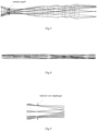
- FIG. 3 shows components of the object lens module and a light path therein.
- the object lens module 02 includes two monolithic lenses, one steering prism, one triple-glued lens, and three double-glued lenses. Through the object lens module of the optical system, the area to be observed can form a clear image after passing through the object lens module.
- FIG. 4 shows a relay module and a light path therein.
- the relay module includes three identical image relay groups, and each image relay group includes two double-glued lenses. After multiple times of imaging by the relay module, the image formed by the object lens module is transmitted in the relay module.
- the relay module of the optical system of the present disclosure may include any number of image relay groups so that a distance from the object lens module to the eye lens module may be of any length.
- FIG. 5 shows a field lens, a field-of-view diaphragm and an associated light path.
- the field lens is disposed at a distance behind the last group of lenses of the relay module, and the image relay-transmitted is folded to reduce the aperture of the optical system of the eye lens module and the optical interface light path module.
- the diameter of the field-of-view diaphragm in this embodiment is 4.1mm, and the size of the field of view is limited at 75°.
- FIG. 6 shows an eye lens module and a light path therein. As shown, the eye lens module includes two double-glued lenses. In this embodiment, the entrance pupil of the eye lens module has a diameter of 5mm, and is disposed 4mm behind the last group of lenses of the eye lens module. As shown in FIG.
- FIG. 7 shows an optical interface light path module and a light path therein. As shown, the optical interface light path module includes three double-glued lenses. It should be noted that the exit pupil of the eye lens module in FIG. 6 is the entrance pupil of the optical interface light path module in FIG. 7 . After passing through the optical interface light path module, the light from the eye lens module becomes a high-definition image on the imaging surface.
- MTF>0.2@40lp/mm or more MTF>0.2@50lp/mm or more, MTF>0.2@60lp/mm or more, MTF>0.2@70lp/mm or more, MTF>0.2@80lp/mm or more, MTF>0.2@90lp/mm or more, MTF>0.2@100lp/mm or more, MTF>0.2@110lp/mm or more, MTF>0.2@120lp/mm or more, MTF>0.2@130lp/mm or more, MTF>0.2@140lp/mm or more, or MTF>0.2@150lp/mm or more.
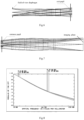
- FIG. 8 is an MTF view of an endoscope system according to an embodiment of the present disclosure.
- the resolution of the optical system may be as high as MTF>0.2@120lp/mm.
- FIG. 9 is an overall MTF view of an object lens module and a relay module according to an embodiment of the present disclosure.
- FIG. 10 is an MTF view of an eye lens module according to an embodiment of the present disclosure.
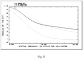
- FIG. 11 is an optical MTF view of an optical interface according to an embodiment of the present disclosure.
- the imaging quality of the object lens module lens only reaches MTF>0.2@40lp/mm.
- the imaging quality of the eye lens module only reaches MTF>0.2@20lp/mm.
- the imaging quality of the optical interface light path module has unexpectedly reached MTF>0.1@120lp/mm.
- the imaging quality of the image formed on the imaging surface of the imaging device is better than the imaging quality of the image output by the object lens module and the relay optical group, or by the eye lens module, or by the optical interface light path module alone.
- the optical transfer function between the object lens module and the relay module, the eye lens module, and the optical interface light path module do not need to consider the imaging quality separately, but the overall optical transfer function (see FIG. 8 ) can meet the design requirements.
- an integrated design method for an endoscope optical system is proposed.
- the design method may be applied to the optical system as described above.
- the optical system includes an object lens module, a relay module and an eye lens module, which are sequentially arranged along a light path direction.
- the method includes: increasing a relative aperture of the system by increasing an exit pupil diameter of the eye lens module; or increasing a relative aperture of the system by increasing an entrance pupil diameter of the object lens module.
- the exit pupil diameter of the eye lens module is 3mm to 6mm.
- the entrance pupil diameter of the object lens module is 0.2mm to 1mm.
- the relative aperture of the system may be increased by increasing the exit pupil diameter of the eye lens module and the entrance pupil diameter of the object lens module simultaneously.
- the entrance pupil diameter of the object lens module is 0.2mm to 1mm
- the exit pupil diameter of the eye lens module is 3mm to 6mm.
- the optical system further includes an optical interface light path module and an imaging device sequentially arranged along the light path direction, wherein the optical interface light path module is closely adjacent to the eye lens module.
- the system is used for a spherical or aspherical endoscope optical system.
- the system is used for an endoscope optical system having an appearance diameter of 1.9mm, 2.7mm, 4mm, 5mm, 6mm, 8mm and 10mm.
- a viewing-direction angle of the system may be 0°, 30°, 45°, or 70° or more.
- a distance from the object lens module to the eye lens module may be of any length.
- an endoscope which includes: the endoscope optical system as described above; or an endoscope optical system designed by the design method as described above.
- the endoscope is a rigid endoscope.
- a method for manufacturing an endoscope includes the following steps: providing an object lens module, a relay module, an eye lens module, an optical interface light path module, and an imaging device along a light path direction; setting an exit pupil diameter of the eye lens module or an entrance pupil diameter of the object lens module to increase a relative aperture of the system; and adjusting one or more of the object lens module, the relay module, the eye lens module, and the optical interface light path module so that an area to be observed forms a high-definition image on an imaging surface of the imaging device.
- the resolution of the high-definition image is MTF>0.2@40lp/mm or more, MTF>0.2@50lp/mm or more, MTF>0.2@60lp/mm or more, MTF>0.2@70lp/mm or more, MTF>0.2@80lp/mm or more, MTF>0.2@90lp/mm or more, MTF>0.2@100lp/mm or more, MTF>0.2@110lp/mm or more, MTF>0.2@.120lp/mm or more, MTF>0.2@130lp/mm or more, MTF>0.2@140lp/mm or more, or MTF>0.2@150lp/mm or more.
- a method for manufacturing an endoscope optical system includes: providing an object lens module, a relay module, and an eye lens module along a light path direction; providing parameters of an optical interface light path module and an imaging device that are adapted to the optical system; setting an exit pupil diameter of the eye lens module or an entrance pupil diameter of the object lens module to increase a relative aperture of the system; and adjusting one or more of the object lens module, the relay module, and the eye lens module so that an image formed by an area to be observed after passing through the object lens module can form a high-definition image on an imaging surface of the imaging device defined by the parameters of the adapted optical interface light path module and the imaging device after being emitted from the relay module and the eye lens module.
- the resolution of the high-definition image is MTF>0.2@40lp/mm or more, MTF>0.2@50lp/mm or more, MTF>0.2@60lp/mm or more, MTF>0.2@70lp/mm or more, MTF>0.2@80lp/mm or more, MTF>0.2@90lp/mm or more, MTF>0.2@100lp/mm or more, MTF>0.2@110lp/mm or more, MTF>0.2@.120lp/mm or more, MTF>0.2@130lp/mm or more, MTF>0.2@140lp/mm or more, or MTF>0.2@150lp/mm or more.
- an optical interface light path module for an endoscope optical system which includes a plurality of lenses, wherein the plurality of lenses receive light emitted, in a form of non-parallel light/divergent light after passing through a relay module and an eyes lens module, from an image formed by an area to be observed after passing through an object lens module, and emit light to form a high-definition image on an imaging surface of an imaging device.
- the resolution of the high-definition image is MTF>0.2@40lp/mm or more, MTF>0.2@50lp/mm or more, MTF>0.2@60lp/mm or more, MTF>0.2@70lp/mm or more, MTF>0.2@80lp/mm or more, MTF>0.2@90lp/mm or more, MTF>0.2@100lp/mm or more, MTF>0.2@110lp/mm or more, MTF>0.2@.120lp/mm or more, MTF>0.2@130lp/mm or more, MTF>0.2@140lp/mm or more, or MTF>0.2@150lp/mm or more.
- the endoscope optical system and endoscope of the present disclosure change the system resolution of the light path by increasing the overall relative aperture of the system, and this design scheme for increasing the relative aperture can be applied not only to a 30° and ⁇ 10mm laparoscope, but also to various appearance diameters such as ⁇ 1.9mm, ⁇ 2.7mm, ⁇ 4mm, ⁇ 5mm, ⁇ 6mm, ⁇ 8mm and ⁇ 10mm, various endoscope lengths, and various viewing-direction angles, such as 0°, 30°, 45° and 70°, without being limited to the diameter specifications, length specifications, and viewing-direction angle specifications listed above.
- a 0° or 30° laparoscope a hysteroscope of a diameter of 10mm, 5mm or 4mm, a cystoscope, an arthroscope, a nasal endoscope, a laryngoscope, an otoscope, an intervertebral endoscope and other rigid endoscopes.
- the endoscope of the present disclosure may also be used in the industrial field.
Landscapes
- Physics & Mathematics (AREA)
- Life Sciences & Earth Sciences (AREA)
- Health & Medical Sciences (AREA)
- Optics & Photonics (AREA)
- Surgery (AREA)
- Engineering & Computer Science (AREA)
- Astronomy & Astrophysics (AREA)
- General Physics & Mathematics (AREA)
- Biomedical Technology (AREA)
- Medical Informatics (AREA)
- Pathology (AREA)
- Radiology & Medical Imaging (AREA)
- Biophysics (AREA)
- Veterinary Medicine (AREA)
- Heart & Thoracic Surgery (AREA)
- Nuclear Medicine, Radiotherapy & Molecular Imaging (AREA)
- Molecular Biology (AREA)
- Animal Behavior & Ethology (AREA)
- General Health & Medical Sciences (AREA)
- Public Health (AREA)
- Multimedia (AREA)
- Lenses (AREA)
- Instruments For Viewing The Inside Of Hollow Bodies (AREA)
- Endoscopes (AREA)
Claims (6)
- Endoskopsystem, das ein Objektlinsenmodul, ein Relaismodul, ein Augenlinsenmodul, ein optisches Schnittstellen-Lichtpfadmodul und eine digitale Ultrahochauflösungskamera umfasst, die nacheinander entlang einer Lichtpfadrichtung angeordnet sind, wobei das Endoskopsystem gemäß einem allgemeinen und integrierten Design mit optimierter Auflösung konfiguriert ist, um ein Bild eines Objekts im Betrachtungsabstand, das durch das Objektlinsenmodul gebildet wird, auf das optische Schnittstellen-Lichtpfadmodul in Form von nicht-parallelem Licht/divergentem Licht zu projizieren, nachdem es durch das Relaismodul und das Augenlinsenmodul hindurchgegangen ist, und es dann auf eine Sensorebene der digitalen Ultrahochauflösungskamera abzubilden.
- Das Endoskopsystem nach Anspruch 1, wobei das Endoskop ein starres Endoskop ist.
- Das Endoskopsystem nach Anspruch 1, wobei das nicht-parallele Licht/divergente Licht ein hochauflösendes Bild auf der Digitalkamera bildet, nachdem es das optische Schnittstellen-Lichtpfadmodul durchlaufen hat.
- Das Endoskopsystem nach einem der Ansprüche 1 bis 3, wobei der Durchmesser der Eintrittspupille des Objektivmoduls 0,2 mm bis 1 mm beträgt.
- Das Endoskopsystem nach einem der Ansprüche 1 bis 4, wobei der Durchmesser der Austrittspupille des Augenlinsenmoduls 3 mm bis 6 mm beträgt.
- Das Endoskopsystem nach einem der Ansprüche 1 bis 3, wobei das System für ein Endoskop mit einem Außendurchmesser von 1,9 mm, 2,7 mm, 4 mm, 5 mm, 6 mm, 8 mm und 10 mm verwendet wird.
Applications Claiming Priority (1)
| Application Number | Priority Date | Filing Date | Title |
|---|---|---|---|
| PCT/CN2017/119501 WO2019127245A1 (zh) | 2017-12-28 | 2017-12-28 | 一种内窥镜系统及内窥镜摄像机光学系统一体化设计方法 |
Publications (4)
| Publication Number | Publication Date |
|---|---|
| EP3674776A1 EP3674776A1 (de) | 2020-07-01 |
| EP3674776A4 EP3674776A4 (de) | 2021-08-18 |
| EP3674776B1 true EP3674776B1 (de) | 2023-10-18 |
| EP3674776C0 EP3674776C0 (de) | 2023-10-18 |
Family
ID=67064207
Family Applications (1)
| Application Number | Title | Priority Date | Filing Date |
|---|---|---|---|
| EP17936800.6A Active EP3674776B1 (de) | 2017-12-28 | 2017-12-28 | Endoskopsystem und integriertes entwurfsverfahren für ein optisches endoskopkamerasystem |
Country Status (3)
| Country | Link |
|---|---|
| US (1) | US12133636B2 (de) |
| EP (1) | EP3674776B1 (de) |
| WO (1) | WO2019127245A1 (de) |
Families Citing this family (1)
| Publication number | Priority date | Publication date | Assignee | Title |
|---|---|---|---|---|
| CN114486195B (zh) * | 2022-01-27 | 2022-11-08 | 中国科学院长春光学精密机械与物理研究所 | 一种适用于光学镜头传递函数检测的像分析器装置和方法 |
Family Cites Families (17)
| Publication number | Priority date | Publication date | Assignee | Title |
|---|---|---|---|---|
| US4905082A (en) * | 1987-05-06 | 1990-02-27 | Olympus Optical Co., Ltd. | Rigid video endoscope having a detachable imaging unit |
| JP2925573B2 (ja) * | 1988-04-28 | 1999-07-28 | オリンパス光学工業株式会社 | 管内観察用内視鏡光学系 |
| US5005957A (en) * | 1988-09-07 | 1991-04-09 | Olympus Optical Co., Ltd. | Objective lens system for endoscopes |
| US5416634A (en) * | 1992-09-11 | 1995-05-16 | United States Surgical Corporation | Optical viewing device |
| US5743846A (en) * | 1994-03-17 | 1998-04-28 | Olympus Optical Co., Ltd. | Stereoscopic endoscope objective lens system having a plurality of front lens groups and one common rear lens group |
| US6069651A (en) * | 1995-04-20 | 2000-05-30 | Olympus Optical Co., Ltd. | Imaging apparatus for endoscopes |
| US9033870B2 (en) * | 2004-09-24 | 2015-05-19 | Vivid Medical, Inc. | Pluggable vision module and portable display for endoscopy |
| JP2008026501A (ja) * | 2006-07-20 | 2008-02-07 | Fujinon Corp | 成形レンズ |
| EP2163933A4 (de) * | 2007-06-12 | 2012-11-28 | Olympus Corp | Optisches element, optisches system und endoskop damit |
| CN102282496B (zh) * | 2009-07-30 | 2013-06-19 | 奥林巴斯医疗株式会社 | 内窥镜用光学系统及内窥镜 |
| WO2014197553A2 (en) * | 2013-06-04 | 2014-12-11 | Bioptigen, Inc. | Hybrid telescope for optical beam delivery and related systems and methods |
| CN104905759B (zh) * | 2014-03-14 | 2017-01-18 | 青岛奥美克医疗科技有限公司 | 一种内窥镜的核心光学系统 |
| EP3345024B1 (de) * | 2015-08-31 | 2023-05-31 | Stryker European Operations Limited | Abbildungssystem aufweisend einen polarisationsfilter und verfahren zum filtern von polarisiertem licht in einem abbildungssystem |
| CN105511085B (zh) * | 2015-11-10 | 2019-03-08 | 河南中光学集团有限公司 | 一种激光扩束融合光学系统 |
| EP4155716A1 (de) * | 2016-01-26 | 2023-03-29 | Stryker European Operations Limited | Bildsensoranordnung |
| WO2017216969A1 (ja) * | 2016-06-17 | 2017-12-21 | オリンパス株式会社 | 明るいリレー光学系及びそれを用いた硬性鏡用光学系、硬性鏡 |
| CN107102433B (zh) | 2017-06-30 | 2019-08-20 | 鹰利视医疗科技有限公司 | 硬管式内窥镜光学成像显示系统 |
-
2017
- 2017-12-28 EP EP17936800.6A patent/EP3674776B1/de active Active
- 2017-12-28 WO PCT/CN2017/119501 patent/WO2019127245A1/zh not_active Ceased
- 2017-12-28 US US16/647,222 patent/US12133636B2/en active Active
Also Published As
| Publication number | Publication date |
|---|---|
| WO2019127245A1 (zh) | 2019-07-04 |
| EP3674776A4 (de) | 2021-08-18 |
| US12133636B2 (en) | 2024-11-05 |
| EP3674776A1 (de) | 2020-07-01 |
| US20200375440A1 (en) | 2020-12-03 |
| EP3674776C0 (de) | 2023-10-18 |
Similar Documents
| Publication | Publication Date | Title |
|---|---|---|
| US11320634B2 (en) | Optical assembly for a compact wide field of view digital camera with low first lens diameter to image diagonal ratio | |
| US9986157B2 (en) | Imaging optical system, camera apparatus and stereo camera apparatus | |
| TWI424188B (zh) | 廣視角取像鏡組 | |
| US9323027B2 (en) | Optical lens system | |
| CN107102433B (zh) | 硬管式内窥镜光学成像显示系统 | |
| US9995910B1 (en) | Optical assembly for a compact wide field of view digital camera with high MTF | |
| US9329364B2 (en) | Optical lens system | |
| US8638507B2 (en) | Fisheye lens system and photographing apparatus | |
| CN105824102B (zh) | 摄像镜头及便携式电子装置 | |
| US8736974B2 (en) | Zoom lens system | |
| TW201617672A (zh) | 光學成像系統 | |
| CN105572843A (zh) | 光学成像系统 | |
| CN107924041B (zh) | 成像镜头和相机模块及包括该相机模块的数字设备 | |
| JPWO2019044934A1 (ja) | 単焦点撮像光学系、レンズユニット、及び撮像装置 | |
| CN103852884A (zh) | 取景器光学系统和图像获取设备 | |
| US9297986B2 (en) | Wide angle lens system and electronic apparatus having the same | |
| US9612422B2 (en) | Photographing lens system | |
| CN108051913B (zh) | 一种内窥镜系统及内窥镜摄像机光学系统一体化设计方法 | |
| US8462447B2 (en) | Photographic lens optical system | |
| WO2021084835A1 (ja) | 光学系及び光学機器 | |
| CN106030367A (zh) | 内窥镜物镜光学系统 | |
| US10859811B2 (en) | Relay optical system and rigid endoscope using the same | |
| EP3674776A1 (de) | Endoskopsystem und integriertes entwurfsverfahren für ein optisches endoskopkamerasystem | |
| US20160161723A1 (en) | Photographing Lens System | |
| US10718935B2 (en) | Endoscope and relay lens system for transmitting an image |
Legal Events
| Date | Code | Title | Description |
|---|---|---|---|
| STAA | Information on the status of an ep patent application or granted ep patent |
Free format text: STATUS: THE INTERNATIONAL PUBLICATION HAS BEEN MADE |
|
| PUAI | Public reference made under article 153(3) epc to a published international application that has entered the european phase |
Free format text: ORIGINAL CODE: 0009012 |
|
| STAA | Information on the status of an ep patent application or granted ep patent |
Free format text: STATUS: REQUEST FOR EXAMINATION WAS MADE |
|
| 17P | Request for examination filed |
Effective date: 20200323 |
|
| AK | Designated contracting states |
Kind code of ref document: A1 Designated state(s): AL AT BE BG CH CY CZ DE DK EE ES FI FR GB GR HR HU IE IS IT LI LT LU LV MC MK MT NL NO PL PT RO RS SE SI SK SM TR |
|
| AX | Request for extension of the european patent |
Extension state: BA ME |
|
| RIN1 | Information on inventor provided before grant (corrected) |
Inventor name: DONG, GUOQING Inventor name: GAO, FENG Inventor name: XIANG, YANG Inventor name: NING, XU Inventor name: LI, QI |
|
| DAV | Request for validation of the european patent (deleted) | ||
| DAX | Request for extension of the european patent (deleted) | ||
| RIC1 | Information provided on ipc code assigned before grant |
Ipc: G02B 23/24 20060101AFI20210312BHEP |
|
| A4 | Supplementary search report drawn up and despatched |
Effective date: 20210721 |
|
| RIC1 | Information provided on ipc code assigned before grant |
Ipc: G02B 23/24 20060101AFI20210715BHEP Ipc: A61B 1/002 20060101ALI20210715BHEP |
|
| STAA | Information on the status of an ep patent application or granted ep patent |
Free format text: STATUS: EXAMINATION IS IN PROGRESS |
|
| 17Q | First examination report despatched |
Effective date: 20220510 |
|
| GRAP | Despatch of communication of intention to grant a patent |
Free format text: ORIGINAL CODE: EPIDOSNIGR1 |
|
| STAA | Information on the status of an ep patent application or granted ep patent |
Free format text: STATUS: GRANT OF PATENT IS INTENDED |
|
| INTG | Intention to grant announced |
Effective date: 20230609 |
|
| GRAS | Grant fee paid |
Free format text: ORIGINAL CODE: EPIDOSNIGR3 |
|
| GRAA | (expected) grant |
Free format text: ORIGINAL CODE: 0009210 |
|
| STAA | Information on the status of an ep patent application or granted ep patent |
Free format text: STATUS: THE PATENT HAS BEEN GRANTED |
|
| AK | Designated contracting states |
Kind code of ref document: B1 Designated state(s): AL AT BE BG CH CY CZ DE DK EE ES FI FR GB GR HR HU IE IS IT LI LT LU LV MC MK MT NL NO PL PT RO RS SE SI SK SM TR |
|
| REG | Reference to a national code |
Ref country code: GB Ref legal event code: FG4D |
|
| REG | Reference to a national code |
Ref country code: CH Ref legal event code: EP |
|
| REG | Reference to a national code |
Ref country code: DE Ref legal event code: R096 Ref document number: 602017075571 Country of ref document: DE |
|
| REG | Reference to a national code |
Ref country code: IE Ref legal event code: FG4D |
|
| U01 | Request for unitary effect filed |
Effective date: 20231117 |
|
| U07 | Unitary effect registered |
Designated state(s): AT BE BG DE DK EE FI FR IT LT LU LV MT NL PT SE SI Effective date: 20240104 |
|
| U20 | Renewal fee for the european patent with unitary effect paid |
Year of fee payment: 7 Effective date: 20231227 |
|
| PG25 | Lapsed in a contracting state [announced via postgrant information from national office to epo] |
Ref country code: GR Free format text: LAPSE BECAUSE OF FAILURE TO SUBMIT A TRANSLATION OF THE DESCRIPTION OR TO PAY THE FEE WITHIN THE PRESCRIBED TIME-LIMIT Effective date: 20240119 |
|
| PG25 | Lapsed in a contracting state [announced via postgrant information from national office to epo] |
Ref country code: IS Free format text: LAPSE BECAUSE OF FAILURE TO SUBMIT A TRANSLATION OF THE DESCRIPTION OR TO PAY THE FEE WITHIN THE PRESCRIBED TIME-LIMIT Effective date: 20240218 |
|
| PG25 | Lapsed in a contracting state [announced via postgrant information from national office to epo] |
Ref country code: ES Free format text: LAPSE BECAUSE OF FAILURE TO SUBMIT A TRANSLATION OF THE DESCRIPTION OR TO PAY THE FEE WITHIN THE PRESCRIBED TIME-LIMIT Effective date: 20231018 |
|
| PG25 | Lapsed in a contracting state [announced via postgrant information from national office to epo] |
Ref country code: IS Free format text: LAPSE BECAUSE OF FAILURE TO SUBMIT A TRANSLATION OF THE DESCRIPTION OR TO PAY THE FEE WITHIN THE PRESCRIBED TIME-LIMIT Effective date: 20240218 Ref country code: GR Free format text: LAPSE BECAUSE OF FAILURE TO SUBMIT A TRANSLATION OF THE DESCRIPTION OR TO PAY THE FEE WITHIN THE PRESCRIBED TIME-LIMIT Effective date: 20240119 Ref country code: ES Free format text: LAPSE BECAUSE OF FAILURE TO SUBMIT A TRANSLATION OF THE DESCRIPTION OR TO PAY THE FEE WITHIN THE PRESCRIBED TIME-LIMIT Effective date: 20231018 |
|
| PG25 | Lapsed in a contracting state [announced via postgrant information from national office to epo] |
Ref country code: RS Free format text: LAPSE BECAUSE OF FAILURE TO SUBMIT A TRANSLATION OF THE DESCRIPTION OR TO PAY THE FEE WITHIN THE PRESCRIBED TIME-LIMIT Effective date: 20231018 Ref country code: PL Free format text: LAPSE BECAUSE OF FAILURE TO SUBMIT A TRANSLATION OF THE DESCRIPTION OR TO PAY THE FEE WITHIN THE PRESCRIBED TIME-LIMIT Effective date: 20231018 Ref country code: NO Free format text: LAPSE BECAUSE OF FAILURE TO SUBMIT A TRANSLATION OF THE DESCRIPTION OR TO PAY THE FEE WITHIN THE PRESCRIBED TIME-LIMIT Effective date: 20240118 Ref country code: HR Free format text: LAPSE BECAUSE OF FAILURE TO SUBMIT A TRANSLATION OF THE DESCRIPTION OR TO PAY THE FEE WITHIN THE PRESCRIBED TIME-LIMIT Effective date: 20231018 |
|
| REG | Reference to a national code |
Ref country code: DE Ref legal event code: R097 Ref document number: 602017075571 Country of ref document: DE |
|
| PG25 | Lapsed in a contracting state [announced via postgrant information from national office to epo] |
Ref country code: CZ Free format text: LAPSE BECAUSE OF FAILURE TO SUBMIT A TRANSLATION OF THE DESCRIPTION OR TO PAY THE FEE WITHIN THE PRESCRIBED TIME-LIMIT Effective date: 20231018 |
|
| PG25 | Lapsed in a contracting state [announced via postgrant information from national office to epo] |
Ref country code: SK Free format text: LAPSE BECAUSE OF FAILURE TO SUBMIT A TRANSLATION OF THE DESCRIPTION OR TO PAY THE FEE WITHIN THE PRESCRIBED TIME-LIMIT Effective date: 20231018 |
|
| PG25 | Lapsed in a contracting state [announced via postgrant information from national office to epo] |
Ref country code: SM Free format text: LAPSE BECAUSE OF FAILURE TO SUBMIT A TRANSLATION OF THE DESCRIPTION OR TO PAY THE FEE WITHIN THE PRESCRIBED TIME-LIMIT Effective date: 20231018 Ref country code: SK Free format text: LAPSE BECAUSE OF FAILURE TO SUBMIT A TRANSLATION OF THE DESCRIPTION OR TO PAY THE FEE WITHIN THE PRESCRIBED TIME-LIMIT Effective date: 20231018 Ref country code: RO Free format text: LAPSE BECAUSE OF FAILURE TO SUBMIT A TRANSLATION OF THE DESCRIPTION OR TO PAY THE FEE WITHIN THE PRESCRIBED TIME-LIMIT Effective date: 20231018 Ref country code: CZ Free format text: LAPSE BECAUSE OF FAILURE TO SUBMIT A TRANSLATION OF THE DESCRIPTION OR TO PAY THE FEE WITHIN THE PRESCRIBED TIME-LIMIT Effective date: 20231018 |
|
| REG | Reference to a national code |
Ref country code: CH Ref legal event code: PL |
|
| PLBE | No opposition filed within time limit |
Free format text: ORIGINAL CODE: 0009261 |
|
| STAA | Information on the status of an ep patent application or granted ep patent |
Free format text: STATUS: NO OPPOSITION FILED WITHIN TIME LIMIT |
|
| PG25 | Lapsed in a contracting state [announced via postgrant information from national office to epo] |
Ref country code: MC Free format text: LAPSE BECAUSE OF FAILURE TO SUBMIT A TRANSLATION OF THE DESCRIPTION OR TO PAY THE FEE WITHIN THE PRESCRIBED TIME-LIMIT Effective date: 20231018 |
|
| PG25 | Lapsed in a contracting state [announced via postgrant information from national office to epo] |
Ref country code: MC Free format text: LAPSE BECAUSE OF FAILURE TO SUBMIT A TRANSLATION OF THE DESCRIPTION OR TO PAY THE FEE WITHIN THE PRESCRIBED TIME-LIMIT Effective date: 20231018 |
|
| 26N | No opposition filed |
Effective date: 20240719 |
|
| GBPC | Gb: european patent ceased through non-payment of renewal fee |
Effective date: 20240118 |
|
| REG | Reference to a national code |
Ref country code: IE Ref legal event code: MM4A |
|
| PG25 | Lapsed in a contracting state [announced via postgrant information from national office to epo] |
Ref country code: IE Free format text: LAPSE BECAUSE OF NON-PAYMENT OF DUE FEES Effective date: 20231228 |
|
| PG25 | Lapsed in a contracting state [announced via postgrant information from national office to epo] |
Ref country code: GB Free format text: LAPSE BECAUSE OF NON-PAYMENT OF DUE FEES Effective date: 20240118 |
|
| PG25 | Lapsed in a contracting state [announced via postgrant information from national office to epo] |
Ref country code: CH Free format text: LAPSE BECAUSE OF NON-PAYMENT OF DUE FEES Effective date: 20231231 |
|
| PG25 | Lapsed in a contracting state [announced via postgrant information from national office to epo] |
Ref country code: IE Free format text: LAPSE BECAUSE OF NON-PAYMENT OF DUE FEES Effective date: 20231228 Ref country code: GB Free format text: LAPSE BECAUSE OF NON-PAYMENT OF DUE FEES Effective date: 20240118 Ref country code: CH Free format text: LAPSE BECAUSE OF NON-PAYMENT OF DUE FEES Effective date: 20231231 |
|
| U20 | Renewal fee for the european patent with unitary effect paid |
Year of fee payment: 8 Effective date: 20241127 |
|
| PG25 | Lapsed in a contracting state [announced via postgrant information from national office to epo] |
Ref country code: CY Free format text: LAPSE BECAUSE OF FAILURE TO SUBMIT A TRANSLATION OF THE DESCRIPTION OR TO PAY THE FEE WITHIN THE PRESCRIBED TIME-LIMIT; INVALID AB INITIO Effective date: 20171228 |
|
| PG25 | Lapsed in a contracting state [announced via postgrant information from national office to epo] |
Ref country code: HU Free format text: LAPSE BECAUSE OF FAILURE TO SUBMIT A TRANSLATION OF THE DESCRIPTION OR TO PAY THE FEE WITHIN THE PRESCRIBED TIME-LIMIT; INVALID AB INITIO Effective date: 20171228 |
|
| PG25 | Lapsed in a contracting state [announced via postgrant information from national office to epo] |
Ref country code: TR Free format text: LAPSE BECAUSE OF FAILURE TO SUBMIT A TRANSLATION OF THE DESCRIPTION OR TO PAY THE FEE WITHIN THE PRESCRIBED TIME-LIMIT Effective date: 20231018 |
|
| U20 | Renewal fee for the european patent with unitary effect paid |
Year of fee payment: 9 Effective date: 20251230 |