EP3674648B1 - Wärmeableitungsanordnung - Google Patents
Wärmeableitungsanordnung Download PDFInfo
- Publication number
- EP3674648B1 EP3674648B1 EP19209605.5A EP19209605A EP3674648B1 EP 3674648 B1 EP3674648 B1 EP 3674648B1 EP 19209605 A EP19209605 A EP 19209605A EP 3674648 B1 EP3674648 B1 EP 3674648B1
- Authority
- EP
- European Patent Office
- Prior art keywords
- flow path
- valve
- heat dissipation
- dissipation assembly
- valve structure
- Prior art date
- Legal status (The legal status is an assumption and is not a legal conclusion. Google has not performed a legal analysis and makes no representation as to the accuracy of the status listed.)
- Active
Links
Images




Classifications
-
- F—MECHANICAL ENGINEERING; LIGHTING; HEATING; WEAPONS; BLASTING
- F16—ENGINEERING ELEMENTS AND UNITS; GENERAL MEASURES FOR PRODUCING AND MAINTAINING EFFECTIVE FUNCTIONING OF MACHINES OR INSTALLATIONS; THERMAL INSULATION IN GENERAL
- F16K—VALVES; TAPS; COCKS; ACTUATING-FLOATS; DEVICES FOR VENTING OR AERATING
- F16K17/00—Safety valves; Equalising valves, e.g. pressure relief valves
- F16K17/003—Safety valves; Equalising valves, e.g. pressure relief valves reacting to pressure and temperature
-
- F—MECHANICAL ENGINEERING; LIGHTING; HEATING; WEAPONS; BLASTING
- F28—HEAT EXCHANGE IN GENERAL
- F28F—DETAILS OF HEAT-EXCHANGE AND HEAT-TRANSFER APPARATUS, OF GENERAL APPLICATION
- F28F3/00—Plate-like or laminated elements; Assemblies of plate-like or laminated elements
- F28F3/12—Elements constructed in the shape of a hollow panel, e.g. with channels
-
- F—MECHANICAL ENGINEERING; LIGHTING; HEATING; WEAPONS; BLASTING
- F16—ENGINEERING ELEMENTS AND UNITS; GENERAL MEASURES FOR PRODUCING AND MAINTAINING EFFECTIVE FUNCTIONING OF MACHINES OR INSTALLATIONS; THERMAL INSULATION IN GENERAL
- F16K—VALVES; TAPS; COCKS; ACTUATING-FLOATS; DEVICES FOR VENTING OR AERATING
- F16K11/00—Multiple-way valves, e.g. mixing valves; Pipe fittings incorporating such valves
- F16K11/10—Multiple-way valves, e.g. mixing valves; Pipe fittings incorporating such valves with two or more closure members not moving as a unit
- F16K11/14—Multiple-way valves, e.g. mixing valves; Pipe fittings incorporating such valves with two or more closure members not moving as a unit operated by one actuating member, e.g. a handle
- F16K11/16—Multiple-way valves, e.g. mixing valves; Pipe fittings incorporating such valves with two or more closure members not moving as a unit operated by one actuating member, e.g. a handle which only slides, or only turns, or only swings in one plane
- F16K11/168—Multiple-way valves, e.g. mixing valves; Pipe fittings incorporating such valves with two or more closure members not moving as a unit operated by one actuating member, e.g. a handle which only slides, or only turns, or only swings in one plane only swings
-
- F—MECHANICAL ENGINEERING; LIGHTING; HEATING; WEAPONS; BLASTING
- F16—ENGINEERING ELEMENTS AND UNITS; GENERAL MEASURES FOR PRODUCING AND MAINTAINING EFFECTIVE FUNCTIONING OF MACHINES OR INSTALLATIONS; THERMAL INSULATION IN GENERAL
- F16K—VALVES; TAPS; COCKS; ACTUATING-FLOATS; DEVICES FOR VENTING OR AERATING
- F16K27/00—Construction of housing; Use of materials therefor
- F16K27/12—Covers for housings
-
- F—MECHANICAL ENGINEERING; LIGHTING; HEATING; WEAPONS; BLASTING
- F16—ENGINEERING ELEMENTS AND UNITS; GENERAL MEASURES FOR PRODUCING AND MAINTAINING EFFECTIVE FUNCTIONING OF MACHINES OR INSTALLATIONS; THERMAL INSULATION IN GENERAL
- F16K—VALVES; TAPS; COCKS; ACTUATING-FLOATS; DEVICES FOR VENTING OR AERATING
- F16K39/00—Devices for relieving the pressure on the sealing faces
- F16K39/04—Devices for relieving the pressure on the sealing faces for sliding valves
- F16K39/045—Devices for relieving the pressure on the sealing faces for sliding valves of rotating or pivoting type
-
- F—MECHANICAL ENGINEERING; LIGHTING; HEATING; WEAPONS; BLASTING
- F28—HEAT EXCHANGE IN GENERAL
- F28F—DETAILS OF HEAT-EXCHANGE AND HEAT-TRANSFER APPARATUS, OF GENERAL APPLICATION
- F28F13/00—Arrangements for modifying heat-transfer, e.g. increasing, decreasing
- F28F13/06—Arrangements for modifying heat-transfer, e.g. increasing, decreasing by affecting the pattern of flow of the heat-exchange media
- F28F13/08—Arrangements for modifying heat-transfer, e.g. increasing, decreasing by affecting the pattern of flow of the heat-exchange media by varying the cross-section of the flow channels
-
- F—MECHANICAL ENGINEERING; LIGHTING; HEATING; WEAPONS; BLASTING
- F28—HEAT EXCHANGE IN GENERAL
- F28F—DETAILS OF HEAT-EXCHANGE AND HEAT-TRANSFER APPARATUS, OF GENERAL APPLICATION
- F28F27/00—Control arrangements or safety devices specially adapted for heat-exchange or heat-transfer apparatus
- F28F27/02—Control arrangements or safety devices specially adapted for heat-exchange or heat-transfer apparatus for controlling the distribution of heat-exchange media between different channels
-
- H—ELECTRICITY
- H05—ELECTRIC TECHNIQUES NOT OTHERWISE PROVIDED FOR
- H05K—PRINTED CIRCUITS; CASINGS OR CONSTRUCTIONAL DETAILS OF ELECTRIC APPARATUS; MANUFACTURE OF ASSEMBLAGES OF ELECTRICAL COMPONENTS
- H05K7/00—Constructional details common to different types of electric apparatus
- H05K7/20—Modifications to facilitate cooling, ventilating, or heating
- H05K7/20218—Modifications to facilitate cooling, ventilating, or heating using a liquid coolant without phase change in electronic enclosures
- H05K7/20281—Thermal management, e.g. liquid flow control
-
- H—ELECTRICITY
- H10—SEMICONDUCTOR DEVICES; ELECTRIC SOLID-STATE DEVICES NOT OTHERWISE PROVIDED FOR
- H10W—GENERIC PACKAGES, INTERCONNECTIONS, CONNECTORS OR OTHER CONSTRUCTIONAL DETAILS OF DEVICES COVERED BY CLASS H10
- H10W40/00—Arrangements for thermal protection or thermal control
- H10W40/40—Arrangements for thermal protection or thermal control involving heat exchange by flowing fluids
- H10W40/47—Arrangements for thermal protection or thermal control involving heat exchange by flowing fluids by flowing liquids, e.g. forced water cooling
-
- F—MECHANICAL ENGINEERING; LIGHTING; HEATING; WEAPONS; BLASTING
- F28—HEAT EXCHANGE IN GENERAL
- F28D—HEAT-EXCHANGE APPARATUS, NOT PROVIDED FOR IN ANOTHER SUBCLASS, IN WHICH THE HEAT-EXCHANGE MEDIA DO NOT COME INTO DIRECT CONTACT
- F28D21/00—Heat-exchange apparatus not covered by any of the groups F28D1/00 - F28D20/00
- F28D2021/0019—Other heat exchangers for particular applications; Heat exchange systems not otherwise provided for
- F28D2021/0028—Other heat exchangers for particular applications; Heat exchange systems not otherwise provided for for cooling heat generating elements, e.g. for cooling electronic components or electric devices
-
- F—MECHANICAL ENGINEERING; LIGHTING; HEATING; WEAPONS; BLASTING
- F28—HEAT EXCHANGE IN GENERAL
- F28D—HEAT-EXCHANGE APPARATUS, NOT PROVIDED FOR IN ANOTHER SUBCLASS, IN WHICH THE HEAT-EXCHANGE MEDIA DO NOT COME INTO DIRECT CONTACT
- F28D21/00—Heat-exchange apparatus not covered by any of the groups F28D1/00 - F28D20/00
- F28D2021/0019—Other heat exchangers for particular applications; Heat exchange systems not otherwise provided for
- F28D2021/0028—Other heat exchangers for particular applications; Heat exchange systems not otherwise provided for for cooling heat generating elements, e.g. for cooling electronic components or electric devices
- F28D2021/0029—Heat sinks
-
- F—MECHANICAL ENGINEERING; LIGHTING; HEATING; WEAPONS; BLASTING
- F28—HEAT EXCHANGE IN GENERAL
- F28F—DETAILS OF HEAT-EXCHANGE AND HEAT-TRANSFER APPARATUS, OF GENERAL APPLICATION
- F28F2250/00—Arrangements for modifying the flow of the heat exchange media, e.g. flow guiding means; Particular flow patterns
- F28F2250/04—Communication passages between channels
-
- F—MECHANICAL ENGINEERING; LIGHTING; HEATING; WEAPONS; BLASTING
- F28—HEAT EXCHANGE IN GENERAL
- F28F—DETAILS OF HEAT-EXCHANGE AND HEAT-TRANSFER APPARATUS, OF GENERAL APPLICATION
- F28F2250/00—Arrangements for modifying the flow of the heat exchange media, e.g. flow guiding means; Particular flow patterns
- F28F2250/06—Derivation channels, e.g. bypass
-
- F—MECHANICAL ENGINEERING; LIGHTING; HEATING; WEAPONS; BLASTING
- F28—HEAT EXCHANGE IN GENERAL
- F28F—DETAILS OF HEAT-EXCHANGE AND HEAT-TRANSFER APPARATUS, OF GENERAL APPLICATION
- F28F2265/00—Safety or protection arrangements; Arrangements for preventing malfunction
- F28F2265/12—Safety or protection arrangements; Arrangements for preventing malfunction for preventing overpressure
-
- H—ELECTRICITY
- H05—ELECTRIC TECHNIQUES NOT OTHERWISE PROVIDED FOR
- H05K—PRINTED CIRCUITS; CASINGS OR CONSTRUCTIONAL DETAILS OF ELECTRIC APPARATUS; MANUFACTURE OF ASSEMBLAGES OF ELECTRICAL COMPONENTS
- H05K7/00—Constructional details common to different types of electric apparatus
- H05K7/20—Modifications to facilitate cooling, ventilating, or heating
- H05K7/2039—Modifications to facilitate cooling, ventilating, or heating characterised by the heat transfer by conduction from the heat generating element to a dissipating body
Definitions
- the present invention relates to a heat dissipation assembly, and in particular, to a heat dissipation assembly that utilizes liquid for heat conduction.
- a water-cooled heat dissipation assembly is one of the common heat dissipation methods, mainly absorbs the heat energy of a heat source (such as a motherboard, a central processing unit or a display chip) via liquid, then discharges the heat-absorbed liquid for heat exchange cooling, and performs cyclic heat dissipation accordingly.
- a heat source such as a motherboard, a central processing unit or a display chip
- the temperature of the heat source (such as the motherboard, the central processing unit or the display chip) is generally affected by the amount of cooling liquid flow. As the flow rate is higher, the heat conduction capability is better.
- the existing water-cooled heat dissipation assembly is usually limited by the space limitation of the heat source, such as uneven width of flow paths often occurs. When liquid flows from a wider flow path to a narrower flow path, the problem of large flow resistance may be caused, thus affecting the heat dissipation efficiency of the heat dissipation assembly.
- DE 10 2017 109890 A1 discloses a flow distributor for distributing a fluid from an inlet manifold to an outlet manifold across a surface to be cooled by the fluid, the manifold comprising: a plurality of flow channels, and a plurality of bypass passages, each communicating between two adjacent flow channels so that the fluid can be transferred between the two adjacent flow channels when one of the two adjacent flow channels is blocked.
- US 2016/126160 A1 discloses a system for cooling dual sides of a power semiconductor device. Disclosed is a system for cooling dual sides of power semiconductor devices including two (2) cooling water flow passages, each of which being bent into the " " or "S" shape, to allow a plurality of power semiconductor devices to be inserted in the cooling water flow passage and to allow each power semiconductor device to be connected to an external device
- EP 2 851 949 A1 discloses a cooling device for cooling an integrated circuit chip (IC), comprising a network of microchannels in which portions of pipes are connected by valves each comprising at least one lamella bilayer.
- US 2009/200007 A1 discloses a heat exchanger having temperature-actuated valves. At least a portion of the valve includes a shape memory material having a thermal transformation temperature. The valve is movable between a first discrete position and a second discrete position, which is determined by the thermal transformation temperature, to allow or block fluid flow through a first channel.
- US 2014/138075 A1 discloses a heat exchanger suitable for cooling a heat source is provided, wherein a bypass channel formed in the heat exchanger has a width greater than a width of other channels to reduce a flow resistance of a fluid and a pumping power for driving a system.
- the present invention provides a heat dissipation assembly according to claim 1 that directs liquid diversion to reduce the probability of non-smooth flow due to excessive flow resistance.
- the heat dissipation assembly of the present invention includes a case and a partition structure.
- the case has a chamber.
- the partition structure includes a partition wall vertically disposed in the chamber to separate a first flow path and a second flow path in the chamber, and the partition wall has a breach and a valve structure disposed at the breach, wherein the valve structure covers the breach when the valve structure is not pushed open.
- a fluid pressure in a section of one of the first flow path and the second flow path which is adjacent to the valve structure is greater than a fluid pressure in a section of the other one of the first flow path and the second flow path which is adjacent to the valve structure, the valve structure is pushed away to expose at least a part of the breach.
- the aforementioned first flow path has a first section and a second section.
- a flow path width of the first section of the first flow path is greater than a flow path width of the second section of the first flow path.
- the valve structure is located at a portion of the first section adjacent to the second section, or the valve structure is located at a boundary between the first section and the second section.
- the aforementioned valve structure includes two valve plates. When the valve structure is pushed away, the two valve plates may be opened in the same direction and stretch into the first flow path together or stretch into the second flow path together.
- valve structure when the valve structure is pushed away, one of the two valve plates is opened and stretches into the first flow path or the second flow path.
- the heat dissipation assembly may further include at least one first stop structure, disposed on at least one of the first flow path and the second flow path to limit an angle at which the two valve plates are opened.
- the heat dissipation assembly may further include at least one second stop structure, disposed beside the two valve plates to limit a direction in which the two valve plates are opened.
- the two valve plates are flexible and fixed to the partition wall.
- the two valve plates are hard valve plates and pivotally connected to the partition wall.
- a ratio of a length of each valve plate to a flow path width of the first flow path may be between 0.2 and 0.6, and a ratio of the length of each valve plate to a flow path width of the second flow path may be between 0.2 and 0.6.
- the two valve plates are adapted to be moved from a closed position to a maximum open position, and each valve plate has a first side connected to the partition wall and a second side opposite to the first side.
- a position of the second side when the valve plate is located at the maximum open position and a position of the second side when the valve plate is located at the closed position are spaced by a distance, a ratio of the distance to a flow path width of the first flow path may be between 0.2 and 0.6, and a ratio of the distance to a flow path width of the second flow path may be between 0.2 and 0.6.
- the heat dissipation assembly of the present invention is provided with a valve structure on a partition structure separating a first flow path and a second flow path.
- the valve structure can be pushed away and closed with the magnitudes of liquid pressures in the first flow path and the second flow path.
- a part of fluid thus flows from a breach to the other flow path to achieve the effect of diversion, thereby reducing a fluid pressure in one of the flow paths and making liquid flow smoothly.
- a part of heat carried by the liquid flowing through a heat source on an original flow path will be discharged out of a chamber in advance via the diversion effect of the valve structure, thereby accelerating partial fluid circulation and improving the heat dissipation efficiency.
- Fig. 1 is an appearance stereogram of a heat dissipation assembly according to an embodiment of the present invention.
- a heat dissipation assembly 100 is adapted to dissipate heat from a heat source (not shown), where the heat source may be, for example, a central processing unit (CPU), a memory, a southbridge chip, a northbridge chip, or a graphic chip on a computer motherboard.
- the heat dissipation assembly 100 has a case 110 and a partition structure 120 disposed in the case 110.
- the case 110 has an upper housing 111 and a lower housing 113, a chamber 112 being formed between the upper housing 111 and the lower housing 113.
- the upper housing 111 includes a first water hole 114 and a second water hole 116.
- the upper housing 111 is indicated by a dashed line in order to clearly show the internal configuration of the case 110.
- the partition structure 120 includes a partition wall 122 vertically disposed in the chamber 112 of the case 110, and the partition wall 122 of the partition structure 120 separates the chamber 112 into a first flow path 150 and a second flow path 160.
- the first flow path 150 is in communication with the second flow path 160.
- Liquid may enter the first flow path 150 from the first water hole 114, flow from the first flow path 150 to the second flow path 160, and then flow from the second flow path 160 to the second water hole 116.
- the present embodiment is exemplified by the liquid entering from the first water hole 114 into the chamber 112 and flowing out from the second water hole 116.
- the liquid may also flow in a reverse direction, which depends on the usage habits of a user and is not limited here.
- the flow resistance may be increased to make liquid difficult to pass.
- the partition structure 120 of the heat dissipation assembly 100 of the present embodiment is provided with a valve structure 124, and fluid pressures in the first flow path 150 and the second flow path 160 can be adjusted to make liquid flow smoothly. This will be explained below.
- Fig. 2 is an enlarged top view of a region A of the heat dissipation assembly of Fig. 1 .
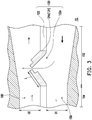
- Fig. 3 is a schematic view of an opened valve structure of the heat dissipation assembly of Fig. 2 .
- the first flow path 150 has a first section 152 and a second section 154.
- the partition wall 122 also has a breach 122a ( FIG.3 ) and a valve structure 124 disposed at the breach 122a.
- the valve structure 124 of the present invention is not only applicable to the heat dissipation assembly 100 as shown in Fig. 1 .
- valve structure 124 on the partition wall 122 of the partition structure 120 is located at a portion of the first section 152 of the first flow path 150 adjacent to the second section 154 of the first flow path 150. In other embodiments, the valve structure 124 on the partition wall 122 may also be located at a boundary between the first section 152 of the first flow path 150 and the second section 154 of the first flow path 150.
- a flow path width of the first section 152 of the first flow path 150 is greater than a flow path width of the second section 154 of the first flow path 150.
- the flow resistance in the first flow path 150 may be affected by a structure such as a fin provided in the second section 154 of the first flow path 150, and the present invention is not limited thereto.
- the flow path width of the second flow path 160 gradually increases with the flow direction.
- the flow resistance at the time of liquid flow decreases, and further, the pressure of the fluid also decreases.
- the valve structure 124 includes two valve plates 124a.
- the two valve plates 124a When the valve structure 124 is pushed away, the two valve plates 124a may be opened in the same direction and stretch into the first flow path 150 or the second flow path 160, so that the two valve plates 124a are adapted to be moved from a closed position P1 to a maximum open position P2.
- valve structure 124 when a fluid pressure existed in a section of the first flow path 150 adjacent to the valve structure 124 is greater than a fluid pressure existed in a section of the second flow path 160 adjacent to the valve structure 124, the valve structure 124 will be pushed away by a fluid, and the two valve plates 124a stretch together into the second flow path 160, so that at least a part of the breach 122a is exposed, and a part of liquid can flow from the first flow path 150 to the second flow path 160 via the breach 122a, and is discharged from the second water hole 116 along the liquid flow direction of the second flow path 160.
- a fluid pressure existed in a section of the second flow path 160 adjacent to the valve structure 124 is greater than a fluid pressure existed in a section of the first flow path 150 adjacent to the valve structure 124, the valve structure 124 will be pushed away by a fluid, the two valve plates 124a stretch together into the first flow path 150, and at least a part of the breach 122a is exposed, so that a part of liquid can flow from the second flow path 160 to the first flow path 150 via the breach 122a.
- the valve structure 124 is disposed at the breach 122a on the partition wall 122 of the heat dissipation assembly 100 , the valve structure can be pushed away and closed with the magnitudes of liquid pressures in the first flow path 150 and the second flow path 160. A part of fluid thus flows through the breach to achieve the effect of diversion, thereby reducing a fluid pressure in one of the flow paths and making liquid flow smoothly. Moreover, a part of heat carried by the liquid flowing through a heat source on an original flow path will be discharged out of a chamber in advance via the diversion effect of the valve structure, thereby accelerating partial fluid circulation and improving the heat dissipation efficiency.
- the material of the valve plate 124a is a flexible material, such as rubber, and the two valve plates 124a are both fixed to the partition wall 122, for example, by injection molding.
- the material of the valve plate 124a is rubber, when the valve structure 124 is pushed away by liquid, the valve plate 124a may exhibit a slight deformation and a bent state and expose a part of the breach 122a to allow a part of liquid to flow.
- the material of the valve plate 124a may also be other suitable designs, and the present invention is not limited thereto.
- the valve plate 124a of the valve structure 124 also has a length L, a ratio of the length L of each valve plate 124a to a flow path width D1 of the first flow path 150 may be, for example, between 0.2 and 0.6, and a ratio of the length L of each valve plate 124a to a flow path width D2 of the second flow path 160 may be, for example, between 0.2 and 0.6.
- Such a design can ensure that the first flow path 150 or the second flow path 160 is not closed or blocked when the valve plate 124a is flipped and/or opened, thereby avoiding the problem of reduction of the heat dissipation efficiency of the heat dissipation assembly 100 caused by non-smooth liquid flow or liquid reflow due to blocking of a flow space of liquid in the first flow path 150 or the second flow path 160.
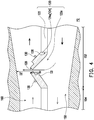
- Fig. 4 is a partial top view of an opened valve structure of a heat dissipation assembly according to another embodiment of the present invention.
- the heat dissipation assembly 100 further includes a first stop structure 130, disposed on the second flow path 160 for limiting a maximum angle at which the valve plate 124a is opened.
- the first stop structure 130 limits the maximum angle at which the valve plate 124a is opened, so that the valve plate 124a can only be pushed to the maximum open position P2 without being over-opened.
- the first stop structure 130 may also be disposed in the first flow path 150.
- the first stop structure 130 is disposed in the first flow path 150 and the second flow path 160 respectively.
- the present invention is not limited thereto.
- the first stop structure 130 may be a convex structure disposed on the upper housing 111 or the lower housing 113 or a columnar structure connecting the upper housing 111 and the lower housing 113.
- each valve plate 124a further has a first side 126 connected to the partition wall 122 and a second side 128 opposite to the first side 126.
- first side 126 connected to the partition wall 122 and a second side 128 opposite to the first side 126.
- a ratio of the distance D3 to a corresponding flow path width of the second flow path 160 is between 0.2 and 0.6.
- the valve plate 124a does not block an excessive flow path space of the second flow path 160, thereby avoiding influence on the heat dissipation efficiency of the heat dissipation assembly 100 ( Fig. 1 ) caused by non-smooth liquid flow or liquid reflow.
- Fig. 5 is a partial stereogram of an opened valve structure of a heat dissipation assembly according to another embodiment of the present invention.
- the difference between a partition structure 120' of Fig. 5 and the partition structure 120 of Fig. 3 is that, in the present embodiment, the valve plates 124a of the valve structure 124 are hard valve plates, each valve plate 124a is pivotally connected to the partition wall 122 by a pivoting portion 70, and each valve plate 124a is adapted to be rotated by liquid relative to the partition wall 122 of the partition structure 120'.
- the material of the valve plate 124a may be a flexible material, the valve plate 124a still can be pivotally connected to the partition wall 122 by the pivoting portion 70.
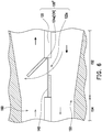
- Fig. 6 is a partial top view of an opened valve structure of a heat dissipation assembly according to another embodiment of the present invention.
- Fig. 7 is a partial stereogram of the opened valve structure of the heat dissipation assembly of Fig. 6 .
- the main difference between a partition structure 120" of Fig. 6 and the partition structure 120 of Fig. 3 is that, in the present embodiment, when the valve structure 124 is pushed away, only one valve plate 124a is opened.
- the pressure of the first flow path 150 is greater than the pressure of the second flow path 160, one of the valve plates 124a will stretch into the second flow path 160 to be opened, while the other valve plate 124a will remain closed.
- the heat dissipation assembly 100 further includes a second stop structure 140, which may be disposed at the breach 122a of the partition wall 122 and located beside the two valve plates 124a to limit a direction in which the two valve plates 124a are opened.
- the second stop structure 140 may be a frame, where the frame (second stop structure 140) allows liquid to pass through and can limit the valve plates 124a, and the two valve plates 124a are respectively disposed on a side of the second stop structure 140 (frame) adjacent to the first flow path 150 and a side of the second stop structure 140 (frame) adjacent to the second flow path 160.
- the frame (second stop structure 140) can be used to limit an opening direction of the two valve plates 124a, so that one of the valve plates 124a can only stretch into the first flow path 150, while the other valve plate 124a can only stretch into the second flow path 160.
- the second stop structure 140 may be designed in other suitable forms, such as a convex shape or a columnar shape. The present invention is not limited thereto.
- first stop structure 130 and the second stop structure 140 can also exist at the same time, and can be disposed in the first flow path 150 and the second flow path 160 or at other suitable positions.
- the present invention is not limited thereto.
- the shapes of the second sides 128 of the two valve plates 124a may be matched to each other.
- the matching may be point-symmetric shape configuration, step-like matching as shown in the figure 3 , or bevel matching, so as to ensure that the valve structure 124 is opened in both directions and can be attached to each other when closed.
- the heat dissipation assembly of the present invention is provided with a valve structure on a partition structure separating a first flow path and a second flow path.
- the valve structure can be pushed away and closed with the magnitudes of liquid pressures in the first flow path and the second flow path.
- a part of fluid thus flows through a breach to achieve the effect of diversion, thereby reducing a fluid pressure in one of the flow paths and making liquid flow smoothly.
- a part of heat carried by the liquid flowing through a heat source on an original flow path will be discharged out of a chamber in advance via the diversion effect of the valve structure, thereby accelerating partial fluid circulation and improving the heat dissipation efficiency.
- the probability that heat dissipation liquid cannot flow smoothly due to excessive flow resistance can be reduced, and the time for partial fluid circulation can be reduced, thereby ensuring good heat dissipation efficiency of the heat dissipation assembly.
Landscapes
- Engineering & Computer Science (AREA)
- General Engineering & Computer Science (AREA)
- Mechanical Engineering (AREA)
- Physics & Mathematics (AREA)
- Thermal Sciences (AREA)
- Microelectronics & Electronic Packaging (AREA)
- Cooling Or The Like Of Electrical Apparatus (AREA)
Claims (9)
- Eine Wärmeableitungsanordnung (100), die Folgendes aufweist:ein Gehäuse (110), das eine Kammer (112) aufweist; undeine Trennstruktur (120, 120', 120"), die eine Trennwand (122) aufweist, die vertikal in der Kammer (112) angeordnet ist, um einen ersten Strömungspfad (150) und einen zweiten Strömungspfad (160) in der Kammer (112) zu trennen, wobei die Trennwand (122) einen Durchbruch (122a) und eine Ventilstruktur (124) aufweist, die an dem Durchbruch (122a) angeordnet ist, wobei die Ventilstruktur (124) den Durchbruch (122a) abdeckt, wenn die Ventilstruktur (124) nicht aufgedrückt ist, undwenn ein Fluiddruck in einem Abschnitt des ersten Strömungspfads (150) oder des zweiten Strömungspfads (160), der an die Ventilstruktur (124) angrenzt, größer ist als ein Fluiddruck in einem Abschnitt des jeweils anderen von dem ersten Strömungspfad (150) und dem zweiten Strömungspfad (160), der an die Ventilstruktur (124) angrenzt, wird die Ventilstruktur (124) weggedrückt, um mindestens einen Teil des Durchbruchs (122a) freizulegen; wobei die Wärmeableitungsanordnung dadurch gekennzeichnet ist, dass der erste Strömungspfad (150) einen ersten Abschnitt (152) und einen zweiten Abschnitt (154) aufweist, eine Strömungspfadbreite (D1) des ersten Abschnitts (152) des ersten Strömungspfads (150) größer ist als eine Strömungspfadbreite (D1) des zweiten Abschnitts (154) des ersten Strömungspfads (150), wobei die Ventilstruktur (124) an einem Teil des ersten Abschnitts (152) angrenzend an den zweiten Abschnitt (154) angeordnet ist, oder die Ventilstruktur (124) an einer Grenze zwischen dem ersten Abschnitt (152) und dem zweiten Abschnitt (154) angeordnet ist.
- Wärmeableitungsanordnung (100) nach Anspruch 1, wobei die Ventilstruktur (124) zwei Ventilplatten (124a) aufweist, und wenn die Ventilstruktur (124) weggedrückt wird, werden die beiden Ventilplatten (124a) in der gleichen Richtung geöffnet und erstrecken sich gemeinsam in den ersten Strömungspfad (150) oder erstrecken sich gemeinsam in den zweiten Strömungspfad (160).
- Wärmeableitungsanordnung (100) nach Anspruch 1, wobei die Ventilstruktur (124) zwei Ventilplatten (124a) aufweist, und wenn die Ventilstruktur (124) weggedrückt wird, eine der beiden Ventilplatten (124a) geöffnet wird und sich in den ersten Strömungspfad (150) oder den zweiten Strömungspfad (160) erstreckt.
- Wärmeableitungsanordnung (100) nach einem der Ansprüche 1 bis 3, wobei die Ventilstruktur (124) zwei Ventilplatten (124a) aufweist, wobei die Wärmeableitungsanordnung (100) weiter Folgendes aufweist:
mindestens eine erste Stoppstruktur (130), die an mindestens einem von dem ersten Strömungspfad (150) und dem zweiten Strömungspfad (160) angeordnet ist, um einen Winkel zu begrenzen, unter dem die beiden Ventilplatten (124a) geöffnet werden. - Wärmeableitungsanordnung (100) nach einem der Ansprüche 1-4, wobei die Ventilstruktur (124) zwei Ventilplatten (124a) aufweist, wobei die Wärmeableitungsanordnung (100) weiter Folgendes aufweist:
mindestens eine zweite Stoppstruktur (140), die neben den beiden Ventilplatten (124a) angeordnet ist, um eine Richtung zu begrenzen, in der die beiden Ventilplatten (124a) geöffnet werden. - Wärmeableitungsanordnung (100) nach einem der Ansprüche 1 bis 5, wobei die Ventilstruktur (124) zwei Ventilplatten (124a) aufweist, die flexibel sind und an der Trennwand (122) befestigt sind.
- Wärmeableitungsanordnung (100) nach einem der Ansprüche 1 bis 5, wobei die Ventilstruktur (124) zwei Ventilplatten (124a) aufweist, die schwenkbar mit der Trennwand (122) verbunden sind.
- Wärmeableitungsanordnung (100) nach einem der Ansprüche 1-7, wobei die Ventilstruktur (124) zwei Ventilplatten (124a) aufweist, wobei ein Verhältnis einer Länge (L) jeder der Ventilplatten (124a) zu einer Strömungspfadbreite (D1) des ersten Strömungspfads (150) zwischen 0,2 und 0,6 liegt, und wobei ein Verhältnis der Länge (L) jeder der Ventilplatten (124a) zu einer Strömungspfadbreite (D2) des zweiten Strömungspfads (160) zwischen 0,2 und 0,6 liegt.
- Wärmeableitungsanordnung (100) nach einem der Ansprüche 1 bis 8, wobei die Ventilstruktur (124) zwei Ventilplatten (124a) aufweist, die angepasst sind um sich von einer geschlossenen Position (P1) in eine maximal geöffnete Position (P2) zu bewegen, jede der Ventilplatten (124a) eine erste Seite (126), die mit der Trennwand (122) verbunden ist, und eine zweite Seite (128) gegenüber der ersten Seite (126), aufweist, eine Position der zweiten Seite (128), wenn sich die Ventilplatte (124a) in der maximal geöffneten Position (P2) befindet, und eine Position der zweiten Seite (128), wenn sich die Ventilplatte (124a) in der geschlossenen Position (P1) befindet, um einen Abstand (D3) beabstandet sind, ein Verhältnis des Abstands (D3) zu einer Strömungspfadbreite (D1) des ersten Strömungspfads (150) zwischen 0,2 und 0,6 liegt, und ein Verhältnis des Abstandes (D3) zu einer Strömungspfadbreite (D2') des zweiten Strömungspfads (160) zwischen 0,2 und 0,6 liegt.
Applications Claiming Priority (1)
| Application Number | Priority Date | Filing Date | Title |
|---|---|---|---|
| TW107147118A TWI701780B (zh) | 2018-12-26 | 2018-12-26 | 散熱組件 |
Publications (2)
| Publication Number | Publication Date |
|---|---|
| EP3674648A1 EP3674648A1 (de) | 2020-07-01 |
| EP3674648B1 true EP3674648B1 (de) | 2021-04-28 |
Family
ID=68609896
Family Applications (1)
| Application Number | Title | Priority Date | Filing Date |
|---|---|---|---|
| EP19209605.5A Active EP3674648B1 (de) | 2018-12-26 | 2019-11-15 | Wärmeableitungsanordnung |
Country Status (3)
| Country | Link |
|---|---|
| US (1) | US11448331B2 (de) |
| EP (1) | EP3674648B1 (de) |
| TW (1) | TWI701780B (de) |
Family Cites Families (9)
| Publication number | Priority date | Publication date | Assignee | Title |
|---|---|---|---|---|
| US4199952A (en) * | 1978-10-10 | 1980-04-29 | Owens-Illinois, Inc. | Modular solar powered heat pump |
| US20090200007A1 (en) | 2008-02-13 | 2009-08-13 | Lockheed Martin Corporation | Heat exchanger having temperature-actuated valves |
| TWI453573B (zh) * | 2011-05-11 | 2014-09-21 | Microjet Technology Co Ltd | 散熱裝置 |
| TWI431737B (zh) * | 2011-08-26 | 2014-03-21 | Microjet Technology Co Ltd | 發光二極體照明裝置及其水冷式散熱模組 |
| TWI482244B (zh) | 2012-11-19 | 2015-04-21 | 財團法人工業技術研究院 | 熱交換器以及半導體模組 |
| FR3010830B1 (fr) | 2013-09-17 | 2016-12-23 | Commissariat Energie Atomique | Dispositif de refroidissement d'une puce de circuit integre |
| KR101653453B1 (ko) | 2014-11-03 | 2016-09-09 | 현대모비스 주식회사 | 전력반도체 양면 냉각방식 냉각장치 |
| DE102017109890A1 (de) | 2017-05-09 | 2018-11-15 | Danfoss Silicon Power Gmbh | Strömungsverteiler und Fluidverteilungssystem |
| TWM554513U (zh) * | 2017-09-15 | 2018-01-21 | Microjet Technology Co Ltd | 氣體輸送裝置 |
-
2018
- 2018-12-26 TW TW107147118A patent/TWI701780B/zh active
-
2019
- 2019-09-28 US US16/586,915 patent/US11448331B2/en active Active
- 2019-11-15 EP EP19209605.5A patent/EP3674648B1/de active Active
Non-Patent Citations (1)
| Title |
|---|
| None * |
Also Published As
| Publication number | Publication date |
|---|---|
| TWI701780B (zh) | 2020-08-11 |
| US11448331B2 (en) | 2022-09-20 |
| US20200208748A1 (en) | 2020-07-02 |
| EP3674648A1 (de) | 2020-07-01 |
| TW202025417A (zh) | 2020-07-01 |
Similar Documents
| Publication | Publication Date | Title |
|---|---|---|
| TWI817607B (zh) | 液冷式散熱裝置 | |
| US12163745B2 (en) | Heat dissipation device and fin structure | |
| US20170257979A1 (en) | Water cooling device | |
| CN110718518B (zh) | 用于cpu散热器热交换的冷却装置 | |
| CN101859738A (zh) | 大面积液冷式散热装置 | |
| TWI694325B (zh) | 水冷頭 | |
| JP2013235967A (ja) | 積層型熱交換器 | |
| KR101611351B1 (ko) | 3d프린터에 의하여 제조되는 수냉식 냉각판 모듈 | |
| CN109588001B (zh) | 双回路液冷系统 | |
| US11448331B2 (en) | Heat dissipation assembly | |
| JP7584059B2 (ja) | 冷却装置 | |
| EP3644159B1 (de) | Wärmeableitungsanordnung und hauptplatinenmodul | |
| JP5251916B2 (ja) | 電子機器の冷却器 | |
| CN207321756U (zh) | 双回路液冷系统 | |
| CN111367385B (zh) | 散热组件 | |
| CN117666735A (zh) | 液流式散热装置 | |
| JP2016096272A (ja) | 冷却器 | |
| CN210628296U (zh) | 用于cpu散热器热交换的冷却装置 | |
| TWI747037B (zh) | 液冷式散熱頭改良結構 | |
| JP2024164337A (ja) | 放熱部材 | |
| EP3760959B1 (de) | Wärmeableitungsvorrichtung | |
| TWI694563B (zh) | 雙迴路液冷系統 | |
| KR102080148B1 (ko) | 수냉식 방열장치 | |
| CN111090317B (zh) | 散热组件及主机板模块 | |
| US20260143636A1 (en) | Cold plate device |
Legal Events
| Date | Code | Title | Description |
|---|---|---|---|
| PUAI | Public reference made under article 153(3) epc to a published international application that has entered the european phase |
Free format text: ORIGINAL CODE: 0009012 |
|
| STAA | Information on the status of an ep patent application or granted ep patent |
Free format text: STATUS: THE APPLICATION HAS BEEN PUBLISHED |
|
| AK | Designated contracting states |
Kind code of ref document: A1 Designated state(s): AL AT BE BG CH CY CZ DE DK EE ES FI FR GB GR HR HU IE IS IT LI LT LU LV MC MK MT NL NO PL PT RO RS SE SI SK SM TR |
|
| AX | Request for extension of the european patent |
Extension state: BA ME |
|
| STAA | Information on the status of an ep patent application or granted ep patent |
Free format text: STATUS: REQUEST FOR EXAMINATION WAS MADE |
|
| 17P | Request for examination filed |
Effective date: 20200817 |
|
| RBV | Designated contracting states (corrected) |
Designated state(s): AL AT BE BG CH CY CZ DE DK EE ES FI FR GB GR HR HU IE IS IT LI LT LU LV MC MK MT NL NO PL PT RO RS SE SI SK SM TR |
|
| GRAP | Despatch of communication of intention to grant a patent |
Free format text: ORIGINAL CODE: EPIDOSNIGR1 |
|
| STAA | Information on the status of an ep patent application or granted ep patent |
Free format text: STATUS: GRANT OF PATENT IS INTENDED |
|
| INTG | Intention to grant announced |
Effective date: 20201123 |
|
| GRAS | Grant fee paid |
Free format text: ORIGINAL CODE: EPIDOSNIGR3 |
|
| GRAA | (expected) grant |
Free format text: ORIGINAL CODE: 0009210 |
|
| STAA | Information on the status of an ep patent application or granted ep patent |
Free format text: STATUS: THE PATENT HAS BEEN GRANTED |
|
| AK | Designated contracting states |
Kind code of ref document: B1 Designated state(s): AL AT BE BG CH CY CZ DE DK EE ES FI FR GB GR HR HU IE IS IT LI LT LU LV MC MK MT NL NO PL PT RO RS SE SI SK SM TR |
|
| REG | Reference to a national code |
Ref country code: GB Ref legal event code: FG4D |
|
| REG | Reference to a national code |
Ref country code: CH Ref legal event code: EP |
|
| REG | Reference to a national code |
Ref country code: AT Ref legal event code: REF Ref document number: 1387528 Country of ref document: AT Kind code of ref document: T Effective date: 20210515 |
|
| REG | Reference to a national code |
Ref country code: DE Ref legal event code: R096 Ref document number: 602019004275 Country of ref document: DE |
|
| REG | Reference to a national code |
Ref country code: IE Ref legal event code: FG4D |
|
| REG | Reference to a national code |
Ref country code: LT Ref legal event code: MG9D |
|
| REG | Reference to a national code |
Ref country code: AT Ref legal event code: MK05 Ref document number: 1387528 Country of ref document: AT Kind code of ref document: T Effective date: 20210428 |
|
| PG25 | Lapsed in a contracting state [announced via postgrant information from national office to epo] |
Ref country code: BG Free format text: LAPSE BECAUSE OF FAILURE TO SUBMIT A TRANSLATION OF THE DESCRIPTION OR TO PAY THE FEE WITHIN THE PRESCRIBED TIME-LIMIT Effective date: 20210728 Ref country code: AT Free format text: LAPSE BECAUSE OF FAILURE TO SUBMIT A TRANSLATION OF THE DESCRIPTION OR TO PAY THE FEE WITHIN THE PRESCRIBED TIME-LIMIT Effective date: 20210428 Ref country code: NL Free format text: LAPSE BECAUSE OF FAILURE TO SUBMIT A TRANSLATION OF THE DESCRIPTION OR TO PAY THE FEE WITHIN THE PRESCRIBED TIME-LIMIT Effective date: 20210428 Ref country code: HR Free format text: LAPSE BECAUSE OF FAILURE TO SUBMIT A TRANSLATION OF THE DESCRIPTION OR TO PAY THE FEE WITHIN THE PRESCRIBED TIME-LIMIT Effective date: 20210428 Ref country code: LT Free format text: LAPSE BECAUSE OF FAILURE TO SUBMIT A TRANSLATION OF THE DESCRIPTION OR TO PAY THE FEE WITHIN THE PRESCRIBED TIME-LIMIT Effective date: 20210428 Ref country code: FI Free format text: LAPSE BECAUSE OF FAILURE TO SUBMIT A TRANSLATION OF THE DESCRIPTION OR TO PAY THE FEE WITHIN THE PRESCRIBED TIME-LIMIT Effective date: 20210428 |
|
| PG25 | Lapsed in a contracting state [announced via postgrant information from national office to epo] |
Ref country code: IS Free format text: LAPSE BECAUSE OF FAILURE TO SUBMIT A TRANSLATION OF THE DESCRIPTION OR TO PAY THE FEE WITHIN THE PRESCRIBED TIME-LIMIT Effective date: 20210828 Ref country code: GR Free format text: LAPSE BECAUSE OF FAILURE TO SUBMIT A TRANSLATION OF THE DESCRIPTION OR TO PAY THE FEE WITHIN THE PRESCRIBED TIME-LIMIT Effective date: 20210729 Ref country code: NO Free format text: LAPSE BECAUSE OF FAILURE TO SUBMIT A TRANSLATION OF THE DESCRIPTION OR TO PAY THE FEE WITHIN THE PRESCRIBED TIME-LIMIT Effective date: 20210728 Ref country code: PL Free format text: LAPSE BECAUSE OF FAILURE TO SUBMIT A TRANSLATION OF THE DESCRIPTION OR TO PAY THE FEE WITHIN THE PRESCRIBED TIME-LIMIT Effective date: 20210428 Ref country code: LV Free format text: LAPSE BECAUSE OF FAILURE TO SUBMIT A TRANSLATION OF THE DESCRIPTION OR TO PAY THE FEE WITHIN THE PRESCRIBED TIME-LIMIT Effective date: 20210428 Ref country code: RS Free format text: LAPSE BECAUSE OF FAILURE TO SUBMIT A TRANSLATION OF THE DESCRIPTION OR TO PAY THE FEE WITHIN THE PRESCRIBED TIME-LIMIT Effective date: 20210428 Ref country code: PT Free format text: LAPSE BECAUSE OF FAILURE TO SUBMIT A TRANSLATION OF THE DESCRIPTION OR TO PAY THE FEE WITHIN THE PRESCRIBED TIME-LIMIT Effective date: 20210830 Ref country code: SE Free format text: LAPSE BECAUSE OF FAILURE TO SUBMIT A TRANSLATION OF THE DESCRIPTION OR TO PAY THE FEE WITHIN THE PRESCRIBED TIME-LIMIT Effective date: 20210428 |
|
| REG | Reference to a national code |
Ref country code: NL Ref legal event code: MP Effective date: 20210428 |
|
| PG25 | Lapsed in a contracting state [announced via postgrant information from national office to epo] |
Ref country code: SK Free format text: LAPSE BECAUSE OF FAILURE TO SUBMIT A TRANSLATION OF THE DESCRIPTION OR TO PAY THE FEE WITHIN THE PRESCRIBED TIME-LIMIT Effective date: 20210428 Ref country code: ES Free format text: LAPSE BECAUSE OF FAILURE TO SUBMIT A TRANSLATION OF THE DESCRIPTION OR TO PAY THE FEE WITHIN THE PRESCRIBED TIME-LIMIT Effective date: 20210428 Ref country code: EE Free format text: LAPSE BECAUSE OF FAILURE TO SUBMIT A TRANSLATION OF THE DESCRIPTION OR TO PAY THE FEE WITHIN THE PRESCRIBED TIME-LIMIT Effective date: 20210428 Ref country code: CZ Free format text: LAPSE BECAUSE OF FAILURE TO SUBMIT A TRANSLATION OF THE DESCRIPTION OR TO PAY THE FEE WITHIN THE PRESCRIBED TIME-LIMIT Effective date: 20210428 Ref country code: DK Free format text: LAPSE BECAUSE OF FAILURE TO SUBMIT A TRANSLATION OF THE DESCRIPTION OR TO PAY THE FEE WITHIN THE PRESCRIBED TIME-LIMIT Effective date: 20210428 Ref country code: RO Free format text: LAPSE BECAUSE OF FAILURE TO SUBMIT A TRANSLATION OF THE DESCRIPTION OR TO PAY THE FEE WITHIN THE PRESCRIBED TIME-LIMIT Effective date: 20210428 Ref country code: SM Free format text: LAPSE BECAUSE OF FAILURE TO SUBMIT A TRANSLATION OF THE DESCRIPTION OR TO PAY THE FEE WITHIN THE PRESCRIBED TIME-LIMIT Effective date: 20210428 |
|
| REG | Reference to a national code |
Ref country code: DE Ref legal event code: R097 Ref document number: 602019004275 Country of ref document: DE |
|
| PLBE | No opposition filed within time limit |
Free format text: ORIGINAL CODE: 0009261 |
|
| STAA | Information on the status of an ep patent application or granted ep patent |
Free format text: STATUS: NO OPPOSITION FILED WITHIN TIME LIMIT |
|
| 26N | No opposition filed |
Effective date: 20220131 |
|
| PG25 | Lapsed in a contracting state [announced via postgrant information from national office to epo] |
Ref country code: IS Free format text: LAPSE BECAUSE OF FAILURE TO SUBMIT A TRANSLATION OF THE DESCRIPTION OR TO PAY THE FEE WITHIN THE PRESCRIBED TIME-LIMIT Effective date: 20210828 Ref country code: AL Free format text: LAPSE BECAUSE OF FAILURE TO SUBMIT A TRANSLATION OF THE DESCRIPTION OR TO PAY THE FEE WITHIN THE PRESCRIBED TIME-LIMIT Effective date: 20210428 |
|
| PG25 | Lapsed in a contracting state [announced via postgrant information from national office to epo] |
Ref country code: MC Free format text: LAPSE BECAUSE OF FAILURE TO SUBMIT A TRANSLATION OF THE DESCRIPTION OR TO PAY THE FEE WITHIN THE PRESCRIBED TIME-LIMIT Effective date: 20210428 |
|
| PG25 | Lapsed in a contracting state [announced via postgrant information from national office to epo] |
Ref country code: LU Free format text: LAPSE BECAUSE OF NON-PAYMENT OF DUE FEES Effective date: 20211115 Ref country code: IT Free format text: LAPSE BECAUSE OF FAILURE TO SUBMIT A TRANSLATION OF THE DESCRIPTION OR TO PAY THE FEE WITHIN THE PRESCRIBED TIME-LIMIT Effective date: 20210428 Ref country code: BE Free format text: LAPSE BECAUSE OF NON-PAYMENT OF DUE FEES Effective date: 20211130 |
|
| REG | Reference to a national code |
Ref country code: BE Ref legal event code: MM Effective date: 20211130 |
|
| PG25 | Lapsed in a contracting state [announced via postgrant information from national office to epo] |
Ref country code: IE Free format text: LAPSE BECAUSE OF NON-PAYMENT OF DUE FEES Effective date: 20211115 |
|
| PG25 | Lapsed in a contracting state [announced via postgrant information from national office to epo] |
Ref country code: CY Free format text: LAPSE BECAUSE OF FAILURE TO SUBMIT A TRANSLATION OF THE DESCRIPTION OR TO PAY THE FEE WITHIN THE PRESCRIBED TIME-LIMIT Effective date: 20210428 |
|
| REG | Reference to a national code |
Ref country code: CH Ref legal event code: PL |
|
| PG25 | Lapsed in a contracting state [announced via postgrant information from national office to epo] |
Ref country code: LI Free format text: LAPSE BECAUSE OF NON-PAYMENT OF DUE FEES Effective date: 20221130 Ref country code: HU Free format text: LAPSE BECAUSE OF FAILURE TO SUBMIT A TRANSLATION OF THE DESCRIPTION OR TO PAY THE FEE WITHIN THE PRESCRIBED TIME-LIMIT; INVALID AB INITIO Effective date: 20191115 Ref country code: CH Free format text: LAPSE BECAUSE OF NON-PAYMENT OF DUE FEES Effective date: 20221130 |
|
| PG25 | Lapsed in a contracting state [announced via postgrant information from national office to epo] |
Ref country code: MK Free format text: LAPSE BECAUSE OF FAILURE TO SUBMIT A TRANSLATION OF THE DESCRIPTION OR TO PAY THE FEE WITHIN THE PRESCRIBED TIME-LIMIT Effective date: 20210428 |
|
| PG25 | Lapsed in a contracting state [announced via postgrant information from national office to epo] |
Ref country code: MT Free format text: LAPSE BECAUSE OF FAILURE TO SUBMIT A TRANSLATION OF THE DESCRIPTION OR TO PAY THE FEE WITHIN THE PRESCRIBED TIME-LIMIT Effective date: 20210428 |
|
| PGFP | Annual fee paid to national office [announced via postgrant information from national office to epo] |
Ref country code: GB Payment date: 20250925 Year of fee payment: 7 |
|
| PGFP | Annual fee paid to national office [announced via postgrant information from national office to epo] |
Ref country code: FR Payment date: 20250908 Year of fee payment: 7 |
|
| PG25 | Lapsed in a contracting state [announced via postgrant information from national office to epo] |
Ref country code: TR Free format text: LAPSE BECAUSE OF FAILURE TO SUBMIT A TRANSLATION OF THE DESCRIPTION OR TO PAY THE FEE WITHIN THE PRESCRIBED TIME-LIMIT Effective date: 20210428 |
|
| PGFP | Annual fee paid to national office [announced via postgrant information from national office to epo] |
Ref country code: DE Payment date: 20250923 Year of fee payment: 7 |