EP3674527A1 - Intake-air temperature controlling device, engine, vehicle, method of intake-air temperature, and computer program prodct - Google Patents
Intake-air temperature controlling device, engine, vehicle, method of intake-air temperature, and computer program prodct Download PDFInfo
- Publication number
- EP3674527A1 EP3674527A1 EP19217774.9A EP19217774A EP3674527A1 EP 3674527 A1 EP3674527 A1 EP 3674527A1 EP 19217774 A EP19217774 A EP 19217774A EP 3674527 A1 EP3674527 A1 EP 3674527A1
- Authority
- EP
- European Patent Office
- Prior art keywords
- passage
- intake
- engine body
- intake air
- engine
- Prior art date
- Legal status (The legal status is an assumption and is not a legal conclusion. Google has not performed a legal analysis and makes no representation as to the accuracy of the status listed.)
- Granted
Links
- 238000000034 method Methods 0.000 title claims description 12
- 238000004590 computer program Methods 0.000 title claims description 4
- 239000002826 coolant Substances 0.000 claims abstract description 145
- 238000002485 combustion reaction Methods 0.000 claims description 99
- 239000000446 fuel Substances 0.000 claims description 33
- 230000006835 compression Effects 0.000 claims description 22
- 238000007906 compression Methods 0.000 claims description 22
- 238000011144 upstream manufacturing Methods 0.000 claims description 19
- 239000000203 mixture Substances 0.000 claims description 14
- 238000007599 discharging Methods 0.000 claims description 7
- 239000012530 fluid Substances 0.000 description 44
- 239000007789 gas Substances 0.000 description 40
- 238000001816 cooling Methods 0.000 description 29
- 230000002159 abnormal effect Effects 0.000 description 18
- 238000001514 detection method Methods 0.000 description 13
- 230000007246 mechanism Effects 0.000 description 12
- 230000003197 catalytic effect Effects 0.000 description 10
- 230000004044 response Effects 0.000 description 10
- XLYOFNOQVPJJNP-UHFFFAOYSA-N water Substances O XLYOFNOQVPJJNP-UHFFFAOYSA-N 0.000 description 6
- 239000003054 catalyst Substances 0.000 description 5
- 230000003134 recirculating effect Effects 0.000 description 5
- 230000008859 change Effects 0.000 description 4
- 230000000694 effects Effects 0.000 description 4
- 238000005516 engineering process Methods 0.000 description 4
- 238000010438 heat treatment Methods 0.000 description 4
- 230000001133 acceleration Effects 0.000 description 3
- 230000001154 acute effect Effects 0.000 description 3
- QVGXLLKOCUKJST-UHFFFAOYSA-N atomic oxygen Chemical compound [O] QVGXLLKOCUKJST-UHFFFAOYSA-N 0.000 description 3
- 229910052760 oxygen Inorganic materials 0.000 description 3
- 239000001301 oxygen Substances 0.000 description 3
- 230000002028 premature Effects 0.000 description 3
- 230000007704 transition Effects 0.000 description 3
- 230000005540 biological transmission Effects 0.000 description 2
- 238000002347 injection Methods 0.000 description 2
- 239000007924 injection Substances 0.000 description 2
- TVMXDCGIABBOFY-UHFFFAOYSA-N octane Chemical compound CCCCCCCC TVMXDCGIABBOFY-UHFFFAOYSA-N 0.000 description 2
- 238000000746 purification Methods 0.000 description 2
- 230000008878 coupling Effects 0.000 description 1
- 238000010168 coupling process Methods 0.000 description 1
- 238000005859 coupling reaction Methods 0.000 description 1
- 238000010586 diagram Methods 0.000 description 1
- 230000006872 improvement Effects 0.000 description 1
- 239000007788 liquid Substances 0.000 description 1
Images


Classifications
-
- F—MECHANICAL ENGINEERING; LIGHTING; HEATING; WEAPONS; BLASTING
- F02—COMBUSTION ENGINES; HOT-GAS OR COMBUSTION-PRODUCT ENGINE PLANTS
- F02D—CONTROLLING COMBUSTION ENGINES
- F02D41/00—Electrical control of supply of combustible mixture or its constituents
- F02D41/30—Controlling fuel injection
- F02D41/3011—Controlling fuel injection according to or using specific or several modes of combustion
- F02D41/3017—Controlling fuel injection according to or using specific or several modes of combustion characterised by the mode(s) being used
- F02D41/3035—Controlling fuel injection according to or using specific or several modes of combustion characterised by the mode(s) being used a mode being the premixed charge compression-ignition mode
- F02D41/3041—Controlling fuel injection according to or using specific or several modes of combustion characterised by the mode(s) being used a mode being the premixed charge compression-ignition mode with means for triggering compression ignition, e.g. spark plug
-
- F—MECHANICAL ENGINEERING; LIGHTING; HEATING; WEAPONS; BLASTING
- F02—COMBUSTION ENGINES; HOT-GAS OR COMBUSTION-PRODUCT ENGINE PLANTS
- F02B—INTERNAL-COMBUSTION PISTON ENGINES; COMBUSTION ENGINES IN GENERAL
- F02B29/00—Engines characterised by provision for charging or scavenging not provided for in groups F02B25/00, F02B27/00 or F02B33/00 - F02B39/00; Details thereof
- F02B29/04—Cooling of air intake supply
- F02B29/0493—Controlling the air charge temperature
-
- F—MECHANICAL ENGINEERING; LIGHTING; HEATING; WEAPONS; BLASTING
- F02—COMBUSTION ENGINES; HOT-GAS OR COMBUSTION-PRODUCT ENGINE PLANTS
- F02B—INTERNAL-COMBUSTION PISTON ENGINES; COMBUSTION ENGINES IN GENERAL
- F02B29/00—Engines characterised by provision for charging or scavenging not provided for in groups F02B25/00, F02B27/00 or F02B33/00 - F02B39/00; Details thereof
- F02B29/04—Cooling of air intake supply
- F02B29/0406—Layout of the intake air cooling or coolant circuit
- F02B29/0437—Liquid cooled heat exchangers
- F02B29/0443—Layout of the coolant or refrigerant circuit
-
- F—MECHANICAL ENGINEERING; LIGHTING; HEATING; WEAPONS; BLASTING
- F02—COMBUSTION ENGINES; HOT-GAS OR COMBUSTION-PRODUCT ENGINE PLANTS
- F02B—INTERNAL-COMBUSTION PISTON ENGINES; COMBUSTION ENGINES IN GENERAL
- F02B29/00—Engines characterised by provision for charging or scavenging not provided for in groups F02B25/00, F02B27/00 or F02B33/00 - F02B39/00; Details thereof
- F02B29/04—Cooling of air intake supply
- F02B29/045—Constructional details of the heat exchangers, e.g. pipes, plates, ribs, insulation, materials, or manufacturing and assembly
- F02B29/0475—Constructional details of the heat exchangers, e.g. pipes, plates, ribs, insulation, materials, or manufacturing and assembly the intake air cooler being combined with another device, e.g. heater, valve, compressor, filter or EGR cooler, or being assembled on a special engine location
-
- F—MECHANICAL ENGINEERING; LIGHTING; HEATING; WEAPONS; BLASTING
- F02—COMBUSTION ENGINES; HOT-GAS OR COMBUSTION-PRODUCT ENGINE PLANTS
- F02B—INTERNAL-COMBUSTION PISTON ENGINES; COMBUSTION ENGINES IN GENERAL
- F02B39/00—Component parts, details, or accessories relating to, driven charging or scavenging pumps, not provided for in groups F02B33/00 - F02B37/00
- F02B39/16—Other safety measures for, or other control of, pumps
-
- F—MECHANICAL ENGINEERING; LIGHTING; HEATING; WEAPONS; BLASTING
- F02—COMBUSTION ENGINES; HOT-GAS OR COMBUSTION-PRODUCT ENGINE PLANTS
- F02D—CONTROLLING COMBUSTION ENGINES
- F02D41/00—Electrical control of supply of combustible mixture or its constituents
- F02D41/0002—Controlling intake air
- F02D41/0007—Controlling intake air for control of turbo-charged or super-charged engines
-
- F—MECHANICAL ENGINEERING; LIGHTING; HEATING; WEAPONS; BLASTING
- F02—COMBUSTION ENGINES; HOT-GAS OR COMBUSTION-PRODUCT ENGINE PLANTS
- F02M—SUPPLYING COMBUSTION ENGINES IN GENERAL WITH COMBUSTIBLE MIXTURES OR CONSTITUENTS THEREOF
- F02M31/00—Apparatus for thermally treating combustion-air, fuel, or fuel-air mixture
- F02M31/02—Apparatus for thermally treating combustion-air, fuel, or fuel-air mixture for heating
- F02M31/04—Apparatus for thermally treating combustion-air, fuel, or fuel-air mixture for heating combustion-air or fuel-air mixture
- F02M31/042—Combustion air
-
- F—MECHANICAL ENGINEERING; LIGHTING; HEATING; WEAPONS; BLASTING
- F02—COMBUSTION ENGINES; HOT-GAS OR COMBUSTION-PRODUCT ENGINE PLANTS
- F02M—SUPPLYING COMBUSTION ENGINES IN GENERAL WITH COMBUSTIBLE MIXTURES OR CONSTITUENTS THEREOF
- F02M31/00—Apparatus for thermally treating combustion-air, fuel, or fuel-air mixture
- F02M31/02—Apparatus for thermally treating combustion-air, fuel, or fuel-air mixture for heating
- F02M31/16—Other apparatus for heating fuel
-
- Y—GENERAL TAGGING OF NEW TECHNOLOGICAL DEVELOPMENTS; GENERAL TAGGING OF CROSS-SECTIONAL TECHNOLOGIES SPANNING OVER SEVERAL SECTIONS OF THE IPC; TECHNICAL SUBJECTS COVERED BY FORMER USPC CROSS-REFERENCE ART COLLECTIONS [XRACs] AND DIGESTS
- Y02—TECHNOLOGIES OR APPLICATIONS FOR MITIGATION OR ADAPTATION AGAINST CLIMATE CHANGE
- Y02T—CLIMATE CHANGE MITIGATION TECHNOLOGIES RELATED TO TRANSPORTATION
- Y02T10/00—Road transport of goods or passengers
- Y02T10/10—Internal combustion engine [ICE] based vehicles
- Y02T10/12—Improving ICE efficiencies
Definitions
- the technology disclosed herein belongs to a technical field related to an intake-air temperature controlling device, an engine, a vehicle, a method of controlling an intake-air temperature, and a computer program product.
- JP3564989B2 discloses a boosted engine provided with a mechanical supercharger which intervenes in the intake passage, an intercooler provided downstream of the mechanical supercharger, a clutch which intercepts and permits the transfer of a driving force to the mechanical supercharger, and an air bypass passage which bypasses the mechanical supercharger.
- the boosted engine disclosed in JP3564989B2 (hereinafter, simply referred to as "the boosted engine”) turns off the clutch to make the mechanical supercharger into a non-driving state, and opens the air bypass passage, when an operating range of the boosted engine is in a low-load low-speed range.
- the boosted engine turns on the clutch and permits the driving force to transmit to the mechanical supercharger, and closes the air bypass passage.
- the coolant is normally circulated to the intercooler to cool the boosted intake air. Therefore, excessively hot intake air immediately after being boosted can be prevent from being supplied to the engine body.
- the engine load becomes high from low.
- the boosted engine transitions to the boosted state from the non-boosted state. Therefore, during the transition of the engine load to high from low, it is necessary to permit the coolant to circulate through the intercooler to cool the boosted intake air.
- the supply of the coolant to the intercooler is started at the moment when the engine load becomes high, a suitable flow rate of the coolant cannot be supplied to the intercooler, and therefore, the response becomes slower.
- the technology disclosed herein is made in view of the situation, and one purpose thereof is to reduce an occurrence of abnormal combustion, when an operating state of an engine body shifts from an operating range in which non-boosted intake air is supplied to the engine body to an operating range in which boosted intake air is supplied to the engine body.
- an intake-air temperature controlling device includes an engine body, an intake passage connected to the engine body, a supercharger provided to the intake passage, a first passage provided to the intake passage, wherein a compressor of the supercharger is provided in the intake passage, a second passage provided to the intake passage, communicating with the first passage at a location at least downstream of the supercharger, and not provided with the supercharger, an intake air flow rate adjuster configured to adjust a ratio of an amount of intake air passing through the first passage to an amount of intake air passing through the second passage, an intercooler provided to the first passage at a location downstream of the supercharger, a pump configured to supply coolant to the intercooler, and a controller configured to control the pump and the intake air flow rate adjuster.
- the controller is configured to output a control signal to the pump so that the coolant is supplied to the intercooler in a first operating range in which the intake air flow rate adjuster is configured to at least partially open the first passage to supply the intake air boosted by the supercharger to the engine body.
- the controller is configured to output a control signal to the pump so that the coolant is supplied to the intercooler in a second operating range in which a load of the engine body is below a given load, and the intake air flow rate adjuster is configured to open the second passage and close the first passage to supply the intake air to the engine body in a natural aspiration state or a non-boosted state.
- the pump is an electric pump configured to increase a discharging amount of the coolant as supplied electric power increases.
- the controller is configured to output a control signal to the pump so that a flow rate of the coolant supplied to the intercooler per unit time in the second operating range becomes less than a flow rate of the coolant supplied to the intercooler per unit time in the first operating range.
- the first operating range is an operating range in which the load of the engine body is equal to or higher than the given load.
- the intake air flow rate adjuster is configured to close the second passage and open the first passage in the first operating range to supply the intake air boosted by the supercharger to the engine body.
- a combustion mode of the engine body when the load of the engine body is equal to or higher than the given load is a combined mode of spark ignition combustion in which spark ignition of a mixture gas of fuel and the intake air is carried out by an ignition plug and compression ignition combustion in which a compression self-ignition of the mixture gas of fuel and the intake air is carried out.
- the second passage is a bypass passage connecting a part of the first passage upstream of the supercharger and a part of the first passage downstream of the intercooler.
- a temperature of the intake air supplied to the engine body in the second operating range is higher than a temperature of the intake air supplied to the engine body in the first operating range.
- a geometric compression ratio of the engine body is 13,1 or higher.
- an engine includes the above intake-air temperature controlling device.
- a vehicle includes the above intake-air temperature controlling device.
- the engine includes an engine body, an intake passage connected to the engine body, a supercharger provided to the intake passage, a first passage provided to the intake passage, a second passage provided to the intake passage, communicating with the first passage at a location at least downstream of the supercharger, and not provided with the supercharger, an intake air flow rate adjuster configured to adjust a ratio of an amount of intake air passing through the first passage to an amount of intake air passing through the second passage, an intercooler provided to the first passage at a location immediately downstream of the supercharger, and a pump configured to supply coolant to the intercooler.
- a compressor of the supercharger is provided in the first passage.
- the method includes controlling the pump so that the coolant is supplied to the intercooler in a first operating range in which the intake air flow rate adjuster at least partially opens the first passage to supply the intake air boosted by the supercharger to the engine body, and controlling the pump so that the coolant is supplied to the intercooler in a second operating range in which a load of the engine body is below a given load, and the intake air flow rate adjuster opens the second passage and closes the first passage to supply the intake air to the engine body in a non-boosted state.
- the pump is an electric pump configured to increase a discharging amount of the coolant as supplied electric power increases.
- a flow rate of the coolant supplied to the intercooler in the second operating range is less than a flow rate of the coolant supplied to the intercooler in the first operating range.
- the first operating range is an operating range in which the load of the engine body is equal to or higher than the given load.
- the method further includes closing the second passage and opening the first passage in the first operating range to supply the intake air boosted by the supercharger to the engine body.
- a computer program product includes computer-readable instructions which, when loaded and executed on an ECU, perform the above method.
- an intake-air temperature controlling device includes an engine body, an intake passage connected to the engine body, a supercharger provided to the intake passage, a first passage provided to the intake passage and including a compressor of the supercharger, a second passage provided to the intake passage, communicating with the first passage at a location at least downstream of the supercharger, and not provided with the supercharger, an intake air flow rate adjuster configured to adjust a ratio of an amount of intake air passing through the first passage to an amount of intake air passing through the second passage, an intercooler provided to the first passage at a location immediately downstream of the supercharger, a pump configured to supply coolant to the intercooler, and a controller comprised of circuitry and configured to control the pump and the intake air flow rate adjuster.
- the controller outputs a control signal to the pump so that the coolant is supplied to the intercooler in a first operating range in which the intake air flow rate adjuster at least partially opens the first passage to supply the intake air boosted by the supercharger to the engine body, and outputs a control signal to the pump so that the coolant is supplied to the intercooler also in a second operating range in which a load of the engine body is below a given load, the intake air flow rate adjuster opens the second passage and closes the first passage to supply the intake air to the engine body in a non-boosted state.
- the intake air boosted by the supercharger can be cooled by the intercooler with a sufficient response. Therefore, when the operating state of the engine body goes into the operating range in which the boosted intake air is supplied to the engine body (hereinafter, referred to as "the boosted range”) from the operating range in which the non-boosted intake air is supplied to the engine body (hereinafter, referred to as "the non-boosted range”), excessively hot intake air can be prevented from being supplied to the engine body. As a result, when the operating state of the engine body goes into the boosted range from the non-boosted range, abnormal combustion can be prevented from occurring.
- the pump may be an electric pump configured to increase a discharging amount of the coolant as supplied electric power increases.
- the controller may output a control signal to the pump so that a flow rate of the coolant supplied to the intercooler per unit time in the second operating range becomes less than a flow rate of the coolant supplied to the intercooler per unit time in the first operating range.
- the power consumption for operating the pump can be reduced.
- the operating state of the engine body goes into the boosted range from the non-boosted range, only increasing the flow rate of the coolant supplied to the intercooler per unit time is required, and thus, the response of cooling the intake air by the intercooler can be improved.
- the first operating range may be an operating range in which the load of the engine body is higher than the given load.
- the intake air flow rate adjuster may close the second passage and open the first passage in the first operating range to supply the intake air boosted by the supercharger to the engine body.
- the load of the engine body when the load of the engine body is high, it is necessary to supply the intake air (especially, fresh air) as much as possible to the engine body, and to positively boost the intake air by the supercharger. Moreover, the load of the engine body is high, it is required to increase the density of the intake air. Thus, the high response to the cooling of the intake air by the intercooler is required. Therefore, when the operating state of the engine body goes into the boosted range from the non-boosted range, the effect of reducing the occurrence of abnormal combustion can be demonstrated more appropriately.
- the intake air especially, fresh air
- a combustion mode of the engine body when the load of the engine body is higher than the given load may be a combined mode of spark ignition (SI) combustion in which jump-spark ignition of a mixture gas comprised of fuel and the intake air is carried out by an ignition plug and compression ignition (CI) combustion in which a compression self-ignition of the mixture gas comprised of fuel and the intake air is carried out.
- SI spark ignition
- CI ignition plug and compression ignition
- a combustion timing of fuel e.g., a timing of combustion peak
- the occurrence timing of CI combustion can be controlled.
- the operating state of the engine body goes into the boosted range from the non-boosted range, since excessively hot intake air is prevented from being supplied to the engine body, CI combustion does not occur at a moment of igniting by the ignition plug.
- the occurrence of abnormal combustion can be further effectively reduced when the operating state of the engine body goes into the boosted range from the non-boosted range.
- the second passage may be a bypass passage connecting a part of the first passage upstream of the supercharger and a part of the first passage downstream of the intercooler.
- a temperature of the intake air supplied to the engine body in the second operating range may be higher than a temperature of the intake air supplied to the engine body in the first operating range.
- the intake air mainly passes through the bypass passage.
- the air inside the first passage is also heated.
- the air inside the first passage can be prevented from being heated by supplying the intercooler coolant to the intercooler. Therefore, the occurrence of abnormal combustion can be further effectively reduced when the operating state of the engine body goes into the boosted range from the non-boosted range.
- a geometric compression ratio of the engine body may be 13:1 or higher.
- Fig. 1 illustrates a configuration of an engine 1 with a supercharger, to which an intake-air temperature controlling device according to Embodiment 1 is applied (hereinafter, simply referred to as "the engine 1").
- the engine 1 is particularly a four-stroke engine which operates by a combustion chamber 17 repeating an intake stroke, a compression stroke, an expansion stroke, and an exhaust stroke.
- the engine 1 is mounted on a vehicle (here, an automobile) with four wheels. The vehicle is propelled by the engine 1.
- Fuel of the engine 1 is liquid fuel of which the main component is gasoline in this configuration example.
- the engine 1 is provided with an engine body 10 having a cylinder block 12 and a cylinder head 13 placed thereon.
- the engine body 10 is a multi-cylinder engine in which a plurality of cylinders 11 are formed inside the cylinder block 12. In Fig. 1 , only one cylinder 11 is illustrated. Other cylinders 11 of the engine body 10 are lined up in a direction perpendicular to the drawing sheet surface of Fig. 1 .
- a piston 3 is slidably inserted in each cylinder 11.
- the piston 3 is coupled to a crankshaft 15 through a connecting rod 14.
- the piston 3 defines the combustion chamber 17 together with the cylinder 11 and the cylinder head 13.
- the "combustion chamber” is not limited to a space thereof when the piston 3 is located at a compression top dead center. Therefore, the term “combustion chamber” may be used in a broader sense. That is, the “combustion chamber” may mean the space formed by the piston 3, the cylinder 11, and the cylinder head 13, regardless of the position of the piston 3.
- a water jacket 12a is formed in the perimeter of each cylinder 11 in the cylinder block 12.
- Engine coolant which cools the engine body 10 circulates inside the water jacket 12a. Although detailed illustration is omitted, after passing through the water jacket 12a, the engine coolant passes through a water jacket formed in the cylinder head 13, and flows out of the engine body 10.
- An intake port 18 is formed in the cylinder head 13 for every cylinder 11.
- the intake port 18 communicates with the combustion chamber 17.
- An intake valve 21 is disposed in the intake port 18.
- the intake valve 21 opens and closes an intake passage between the combustion chamber 17 and the intake port 18.
- the intake valve 21 is opened and closed at a given timing by a valve operating mechanism.
- the valve operating mechanism may be a variable valve operating mechanism which varies a valve timing and/or a valve lift.
- the variable valve operating mechanism particularly has an intake electric S-VT (Sequential-Valve Timing) 23 (refer to Fig. 6 ).
- the intake electric S-VT 23 is configured to continuously change a rotation phase of an intake cam shaft within a given angle range. Therefore, an open timing and a close timing of the intake valve 21 are continuously changed.
- the intake valve operating mechanism may have a hydraulic S-VT, instead of the electric S-VT.
- An exhaust port 19 is formed in the cylinder head 13 for every cylinder 11.
- the exhaust port 19 communicates with the combustion chamber 17.
- An exhaust valve 22 is disposed in the exhaust port 19.
- the exhaust valve 22 opens and closes an exhaust passage between the combustion chamber 17 and the exhaust port 19.
- the valve operating mechanism By the valve operating mechanism, the exhaust valve 22 is opened and closed at a given timing.
- This valve operating mechanism may be a variable valve operating mechanism which varies a valve timing and/or a valve lift.
- the variable valve operating mechanism particularly has an exhaust electric S-VT 24 (refer to Fig. 6 ).
- the exhaust electric S-VT 24 is configured to continuously change a rotation phase of an exhaust cam shaft within a given angle range. Thus, an open timing and a close timing of the exhaust valve 22 are changed continuously.
- the exhaust valve operating mechanism may have a hydraulic S-VT, instead of the electric S-VT.
- An injector 6 which directly injects fuel into the cylinder 11 is attached to the cylinder head 13 for every cylinder 11.
- the injector 6 is disposed so that its nozzle holes face the combustion chamber 17 from a center part of a ceiling surface of the combustion chamber 17 (in detail, a part slightly at the exhaust side from the center).
- the injector 6 directly injects an amount of fuel according to the operating state of the engine body 10 into the combustion chamber 17 at an injection timing set according to the operating state of the engine body 10.
- An ignition plug 25 is attached to the cylinder head 13 for every cylinder 11.
- the ignition plug 25 forcibly ignites a mixture gas inside the combustion chamber 17.
- the ignition plug 25 is disposed at the intake side. Electrodes of the ignition plug 25 face the inside of the combustion chamber 17, and are located near the ceiling surface of the combustion chamber 17. Note that the ignition plug 25 may be disposed at the exhaust side.
- the injector 6 may be disposed at the intake side or the exhaust side of the center axis of the cylinder 11.
- the geometric compression ratio of the engine 1 may be set as 14:1 to 17:1 in a regular gasoline specification (the octane number of fuel is about 91), and may also be set as 15:1 to 18:1 in a high-octane specification (the octane number of fuel is about 96).
- An intake passage 40 is connected to one side of the engine body 10.
- the intake passage 40 communicates with the intake port 18 of each cylinder 11.
- the intake passage 40 is a passage through which intake air introduced into the combustion chamber 17 circulates.
- the intake passage 40 according to this embodiment has a first air intake part 141 which takes in fresh air at the same temperature as the ambient temperature to the intake passage 40, and a second air intake part 142 which takes in the fresh air at a temperature higher than the ambient temperature to the intake passage 40.
- the configurations of the air intake parts 141 and 142 will be described later.
- An air cleaner 41 which filters the fresh air is disposed in the intake passage 40 at a part immediately downstream of the air intake parts 141 and 142.
- a surge tank 42 is disposed near the downstream end of the intake passage 40.
- a part of the intake passage 40 downstream of the surge tank 42 constitutes independent passages branched for every cylinder 11. The downstream end of the independent passage is connected to the intake port 18 of each cylinder 11.
- a throttle valve 43 is disposed between the air cleaner 41 and the surge tank 42 in the intake passage 40.
- the throttle valve 43 varies an opening of a valve to adjust an amount of fresh air introduced into the combustion chamber 17.
- the supercharger 44 boosts intake air introduced into the combustion chamber 17.
- the supercharger 44 is particularly a supercharger which is driven by the engine body 10.
- the supercharger 44 may be a Lysholm type, for example.
- the configuration of the supercharger 44 is not limited in particular.
- the supercharger 44 may also be a root type, a vane type, or a centrifugal type.
- the supercharging side passage 40a is one example of a first passage.
- An intercooler 46 is particularly disposed immediately downstream of the supercharger 44 in the supercharging side passage 40a.
- the intercooler 46 cools intake air compressed by the supercharger 44.
- the intercooler 46 is of a fluid-cooling type, and intercooler coolant circulates therethrough.
- the intercooler coolant is coolant different from the engine coolant.
- a bypass passage 47 is particularly connected to the intake passage 40.
- the bypass passage 47 connects a part of the supercharging side passage 40a upstream of the supercharger 44 to a part downstream of the intercooler 46 so as to bypass the supercharger 44 and the intercooler 46. That is, the bypass passage 47 communicates to the supercharging side passage 40a at least downstream of the supercharger 44.
- the bypass passage 47 is not provided with the supercharger.
- the bypass passage 47 is one example of a second passage.
- An air bypass valve 48 which opens and closes the bypass passage 47 is disposed in the bypass passage 47.
- the air bypass valve 48 is an on-off valve.
- the air bypass valve 48 When the supercharger 44 is not driven (i.e., when the electromagnetic clutch 45 is disconnected), the air bypass valve 48 is made into an open state (ON state). Therefore, gas which flows through the intake passage 40 bypasses the supercharger 44, and is introduced into the combustion chamber 17 of the engine 1.
- the engine 1 is operated in a non-boosted state (i.e., natural aspirated state).
- the electromagnetic clutch 45 and the air bypass valve 48 are examples of an intake air flow rate adjuster which adjusts a ratio of the amount of intake air passing through the supercharging side passage 40a and the amount of intake air passing through the bypass passage 47.
- the air bypass valve 48 may be comprised of a valve which can continuously vary its opening.
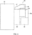
- Figs. 2 and 3 schematically illustrate a layout of the supercharging side passage 40a and the bypass passage 47 with respect to the engine body 10. Note that in Figs. 2 and 3 , illustration of an exhaust gas recirculation (EGR) passage 52 and the exhaust passage 50 (described later) is omitted.
- EGR exhaust gas recirculation
- the bypass passage 47 branches upwardly at a part of the intake passage 40 between the throttle valve 43 and the supercharger 44.
- the bypass passage 47 extends upwardly from the branch part and extends toward one side of the cylinder lined-up direction, and then extends downwardly and extends toward the surge tank 42 in an intake manifold 49.
- the intake manifold 49 includes the surge tank 42 and the independent passage described above.
- the supercharging side passage 40a extends downwardly from the supercharger 44, then extends toward the engine body 10 and is connected to the bypass passage 47 in the intake manifold 49.
- the supercharging side passage 40a and the bypass passage 47 are disposed close to each other in the vertical direction. Therefore, for example, when the bypass passage 47 is heated by intake air, the supercharging side passage 40a is also heated by the heat transfer.
- An exhaust passage 50 is connected to the other side of the engine body 10.
- the exhaust passage 50 communicates with the exhaust port 19 of each cylinder 11.
- the exhaust passage 50 is a passage through which exhaust gas discharged from the combustion chamber 17 circulates. Although detailed illustration of an upstream part of the exhaust passage 50 is omitted, it constitutes independent passages branched for every cylinder 11. The upstream end of the independent passage is connected to the exhaust port 19 of each cylinder 11.
- An exhaust gas purification system having a plurality of catalytic converters is disposed in the exhaust passage 50.
- the upstream catalytic converter has a three-way catalyst 511 and a GPF (Gasoline Particulate Filter) 512.
- a downstream catalytic converter is disposed outside the engine bay.
- the downstream catalytic converter has a three-way catalyst 513.
- the exhaust gas purification system is not limited to the illustrated configuration.
- the GPF may be omitted.
- the catalytic converter is not limited to those having the three-way catalyst.
- the disposed order of the three-way catalyst and the GPF may be change suitably.
- An EGR passage 52 which constitutes an external EGR system is particularly connected between the intake passage 40 and the exhaust passage 50.
- the EGR passage 52 is a passage which recirculates a portion of exhaust gas to the intake passage 40.
- the upstream end of the EGR passage 52 is connected to the exhaust passage 50 between the upstream catalytic converter and the downstream catalytic converter.
- the downstream end of the EGR passage 52 is connected to the intake passage 40 at a location upstream of the supercharger 44.
- Exhaust gas which flows through the EGR passage 52 (hereinafter, referred to as "the EGR gas”) enters into the intake passage 40 upstream of the supercharger 44, without passing through the air bypass valve 48 of the bypass passage 47, when introduced into the intake passage 40.
- An EGR cooler 53 of a fluid cooling type is disposed in the EGR passage 52.
- the EGR cooler 53 cools the EGR gas passing through the EGR passage 52.
- An EGR valve 54 is disposed in the EGR passage 52.
- the EGR valve 54 is configured to adjust a flow rate of the EGR gas which flows through the EGR passage 52. By varying the opening of the EGR valve 54, a recirculating amount of the cooled EGR gas can be adjusted.
- the EGR valve 54 may be comprised of an on-off valve, or may be comprised of a valve which can continuously vary the valve opening.
- the cooling system of the engine 1 particularly includes a first cooling path 60 which cools the engine body 10 by circulating the engine coolant in the engine body 10, and a second cooling path 70 which cools intake air after passing through the supercharger 44 by circulating the intercooler coolant in the intercooler 46.
- the first cooling path 60 is particularly provided with a first pump 61, a first radiator 62 configured to cool the engine coolant which flows through the first cooling path 60, and a flow rate control valve 63 which adjusts a flow rate of the engine coolant circulating through the first cooling path 60.
- the first pump 61 is particularly a mechanical pump which is driven by the crankshaft 15 of the engine body 10 in an interlocked manner.
- a discharge port of the first pump 61 is connected to the water jacket 12a of the engine body 10.
- the first radiator 62 particularly cools the engine coolant which passes through the water jacket of the engine body 10 and is discharged from the cylinder head 13.
- the first radiator 62 cools the engine coolant by outside air when a vehicle to which the engine 1 is mounted travels forward.
- the flow rate control valve 63 is particularly disposed at an intermediate location of a path through which the engine coolant which is discharged from the first radiator 62 and flows into the first pump 61 passes. That is, the flow rate control valve 63 is disposed at the entrance side into the engine body 10 in the first cooling path 60.
- the flow rate control valve 63 is comprised of an electric thermostat valve.
- the flow rate control valve 63 is a valve in which a heating wire is built into the thermostat valve. Fundamentally, when the temperature of the engine coolant is above a preset fluid temperature setting, the flow rate control valve 63 is configured to open according to the temperature. However, by applying an electric current to the heating wire, it can open even when the temperature of the engine coolant is below the fluid temperature setting.
- Fig. 5 illustrates one example of a characteristic of the flow rate control valve 63 to the temperature of the engine coolant.
- the temperature of the engine coolant illustrated on the horizontal axis is the temperature at the location of the flow rate control valve 63, and it differs from the temperature of the engine coolant which flows into the first radiator 62.
- the flow rate control valve 63 begins to open when the temperature of the engine coolant is particularly about 95°C to about 96°C. On the other hand, when the power is supplied, it can open even if the temperature of the engine coolant is below about 95°C. As illustrated in Fig. 5 , the temperature at which the flow rate control valve 63 begins to open is lowered as the current supplied to the heating wire increases. Moreover, the opening of the flow rate control valve 63 while the temperature is constant can be increased as the current supplied to the heating wire increases, within a range of the opening of the flow rate control valve 63 being smaller than a fully opened state. Note that, in this embodiment, the fluid temperature setting is particularly set as about 95°C to about 97°C. Moreover, the flow rate control valve 63 may be an electromagnetic valve, such as a solenoid valve, instead of the thermostat valve.
- the power supplied to the flow rate control valve 63 is adjusted based on the operating state of the engine body 10, the ambient temperature, etc. so that the temperature of the engine coolant becomes a suitable temperature.
- the first cooling path 60 also passes through the EGR cooler 53. That is, the EGR gas passing through the EGR passage 52 is cooled by a heat exchange with the engine coolant.
- the second pump 71 is particularly an electric pump driven by electric power.
- the second pump 71 is configured to increase a discharging amount of the intercooler coolant as the supplied electric power increases.
- the second radiator 72 particularly cools the intercooler coolant discharged from the intercooler 46.
- the second radiator 72 is particularly disposed below and adjacent to the first radiator 62.
- the second radiator 72 cools the intercooler coolant by outside air when the vehicle to which the engine 1 is mounted travels forward.
- the intercooler coolant cooled by the second radiator 72 flows into the second pump 71.
- the cooling system of the engine 1 particularly includes a grille shutter 81 and a radiator fan 82, as a mechanism to send the outside air to the first and second radiators 62 and 72.
- the grille shutter 81 is particularly provided to a location of the vehicle forward of the first and second radiators 62 and 72.
- the grille shutter 81 is particularly comprised of a plurality of flappers 81a which rotate on respective axes extending in the vehicle width direction.
- the grille shutter 81 is fully opened when the flappers 81a become perpendicular to the vertical direction, and is fully closed when the flappers 81a become substantially parallel to the vertical direction.
- a flow rate of the air taken in into the engine bay i.e., an amount of the outside air which flows to the first and second radiators 62 and 72, is adjusted by the angle of the flappers 81a with respect to the vertical direction.
- the angle of the flappers 81a with respect to the vertical direction is adjustable electrically.
- vertical direction refers to the up-and-down direction of the vehicle 1 and normally corresponds to a direction perpendicular to a road surface.
- forward and “rearward” in the vehicle mean the directions when the vehicle is oriented normally.
- the radiator fan 82 is particularly provided rearward of the first and second radiators 62 and 72 and forward of the second air intake part 142.
- the radiator fan 82 draws the outside air by rotating to assist the outside air to flow through the first and second radiators 62 and 72.
- the radiator fan 82 is particularly configured to increase a drawing amount of the outside air as its rotational speed increases.
- the radiator fan 82 is configured to be electrically adjustable of the rotational speed.
- the outside air taken in through the grille shutter 81 particularly cools the coolant which flows through the first and second radiators 62 and 72 by a heat exchange with the coolant.
- the outside air which passed through the first and second radiators 62 and 72 flows rearward of the radiator fan 82.
- the intake passage 40 particularly has the two air intake parts comprised of the first and second air intake parts 141 and 142.
- the first air intake part 141 is particularly located in front or forward of the radiators 62 and 72, in more detail, in front or forward of the grille shutter 81.
- the first air intake part 141 takes in the outside air (air not heated) to the intake passage 40.
- the second air intake part 142 is particularly located behind or rearward of the radiators 62 and 72, in more detail, behind or rearward of the radiator fan 82.
- the second air intake part 142 takes in air (outside air), which passes through the first and second radiators 62 and 72 and flows rearward of the radiator fan 82, to the intake passage 40. That is, air heated by heat exchange with the coolant which flows through the first and second radiators 62 and 72 is taken from the second air intake part 142. Thus, the second air intake part 142 takes in air, at a temperature higher than the ambient temperature, to the intake passage 40.
- the first and second air intake parts 141 and 142 is particularly provided with an intake air switch valve 143.
- a valve of the intake air switch valve 143 is disposed at each of the first and second air intake parts 141 and 142, and the valves operate in an interlocked manner.
- the opening of the valve of the second air intake part 142 becomes smaller as the opening of the valve of first air intake part 141 becomes larger.
- the intake air switch valve 143 changes the opening of each valve in the interlocked manner by coupling the valves through a common axis. Note that the intake air switch valve 143 provided to the first air intake part 141 and the intake air switch valve 143 provided to the second air intake part 142 may be configured to be adjustable of the valve openings independently.
- a controlling device of the engine 1 is provided with the ECU (Electronic Control Unit or Engine Control Unit) 100 for operating the engine 1.
- the ECU 100 is a controller based on a well-known microcomputer, and as illustrated in Fig. 6 , includes a processor (e.g., a central processing unit (CPU)) 101 which executes a program, memory 102 which is comprised of RAM (Random Access Memory) and/or ROM (Read Only Memory) for example, and stores the programs and data, and an input/output bus 103 which inputs and outputs an electrical signal.
- a processor e.g., a central processing unit (CPU)
- memory 102 which is comprised of RAM (Random Access Memory) and/or ROM (Read Only Memory) for example, and stores the programs and data
- an input/output bus 103 which inputs and outputs an electrical signal.
- the ECU 100 is connected to one or more sensors, particularly various kinds of sensors SW1-SW8.
- the sensors SW1-SW8 each output a detection signal to the ECU 100.
- the sensors include the following sensors.
- an airflow sensor SW1 which is disposed downstream of the air cleaner 41 in the intake passage 40 and detects a flow rate of fresh air flowing through the intake passage 40
- an intake temperature sensor SW2 which is attached to the surge tank 42 and detects the temperature of intake air supplied to the combustion chamber 17
- an exhaust temperature sensor SW3 which is disposed at the exhaust passage 50 and detects the temperature of exhaust gas discharged from the combustion chamber 17
- a linear O 2 sensor SW4 which is disposed upstream of the upstream catalytic converter in the exhaust passage 50 and detects an oxygen concentration in the exhaust gas
- a lambda ( ⁇ ) O 2 sensor SW5 which is disposed downstream of the three-way catalyst 511 in the upstream catalytic converter and detects an oxygen concentration in the exhaust gas
- a fluid temperature sensor SW6 which is attached to the cylinder head 13 of the engine body 10 and detects the temperature of the engine coolant
- a crank angle sensor SW7 which is attached to the engine body 10 and detects a rotation angle of the crankshaft 15
- the ECU 100 particularly determines the operating state of the engine body 10 and calculates a controlled amount (parameter) of each device based on these detection signals.
- the ECU 100 particularly outputs a control signal according to the calculated controlled amount to each of the injector 6, the ignition plug 25, the intake electric S-VT 23, the exhaust electric S-VT 24, the throttle valve 43, the electromagnetic clutch 45 of the supercharger 44, the air bypass valve 48, the EGR valve 54, the flow rate control valve 63, the second pump 71, the grille shutter 81, the radiator fan 82, and the intake air switch valve 143.
- the ECU 100 calculates an engine speed of the engine body 10 based on the detection signal of the crank angle sensor SW7.
- the ECU 100 calculates an engine load of the engine body 10 based on the detection signal of the accelerator opening sensor SW8.
- the ECU 100 particularly sets a target EGR rate (i.e., a ratio of the EGR gas to the entire gas inside the combustion chamber 17) based on the operating state of the engine body 10 (mainly, the engine load and the engine speed) and a preset map. Then, the ECU 100 determines a target EGR amount based on the target EGR rate and an intake air amount based on the detection signal of the accelerator opening sensor SW8. Moreover, by adjusting the opening of the EGR valve 54, the ECU 100 performs a feedback control so that the external EGR amount introduced into the combustion chamber 17 becomes the target EGR amount.
- a target EGR rate i.e., a ratio of the EGR gas to the entire gas inside the combustion chamber 17
- the ECU 100 particularly performs an air-fuel ratio feedback control when a given control condition is satisfied. Specifically, based on the oxygen concentrations in the exhaust gas detected by the linear O 2 sensor SW4 and the lambda O 2 sensor SW5, the ECU 100 adjusts a fuel injection amount of the injector 6 so that the air-fuel ratio of the mixture gas becomes a desired value.
- the ECU 100 particularly sets a flow rate of the intercooler coolant supplied to the intercooler 46 per unit time based on the operating state of the engine body 10 and a preset map. Then, the ECU 100 sets the electric power supplied to the second pump 71 so that the flow rate of the setting is discharged from the second pump 71.
- Fig. 7 particularly illustrates an operating range map of the engine 1 when the engine 1 is warm (i.e., after a warmup of the engine body 10).
- the operating range map of the engine 1 is particularly defined by the engine load and the engine speed, and is divided into two or more particularly three ranges depending on the engine load and the engine speed.
- the three ranges are comprised of a range A where an idle operation is included, the engine speed is low below a given engine speed Ne, and the engine load is low below a given load Tq, a range B where the engine speed is high above the given engine speed Ne, and the engine load is below the given load Tq, and a range C where the engine load is the given load Tq and above.
- the given engine speed Ne may be about 3,500 rpm, for example.
- the range A may contain an engine speed range equal to or more than the given engine speed Ne, i.e., 3,500 rpm.
- the phrase "after the warm-up of the engine body 10" as used herein refers to a state where the temperature of the engine coolant detected by the fluid temperature sensor SW6 is about 80°C or more, and the temperature of the intake air detected by the intake temperature sensor SW2 is about 25°C or more.
- the engine 1 performs SPCCI combustion which is the combination of SI combustion and CI combustion in all the ranges A-C in order to mainly improve combustion stability and fuel efficiency.
- SPCCI combustion is the combination of SI combustion and CI combustion in all the ranges A-C in order to mainly improve combustion stability and fuel efficiency.
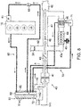
- the ECU 100 controls the temperature of intake air introduced into the engine body 10 by using the cooling system of the engine 1. Below, operation of the engine 1 in each range is described in detail with reference to Figs. 8 to 10 .
- the engine 1 performs SPCCI combustion in a state where an air-fuel ratio (A/F) of the mixture gas inside the combustion chamber 17 or a gas-fuel ratio (G/F) which is a relation between the total gas weight G inside the cylinder 11 and the weight F of fuel fed to the cylinder 11 is in a lean state which is larger than a stoichiometric air-fuel ratio.
- A/F air-fuel ratio
- G/F gas-fuel ratio
- fuel is injected from the injector 6 so that A/F or G/F becomes about 25:1 or more, and the ignition plug 25 is operated at a desired timing.
- the ECU 100 particularly controls and operates each device so that intake air at or above a first intake air temperature Ta1 is introduced into the engine body 10. Note that this first intake air temperature Ta1 is about 80°C, for example.
- the ECU 100 when the operating state of the engine body 10 is in the range A, as illustrated in Fig. 8 , the ECU 100 particularly outputs the control signal to the intake air switch valve 143 so that the first air intake part 141 particularly becomes fully closed and the second air intake part 142 becomes fully opened. Moreover, the ECU 100 particularly outputs control signals to the electromagnetic clutch 45 and the air bypass valve 48 to disconnect the electromagnetic clutch 45 and fully open the air bypass valve 48 so that the supercharger 44 is not driven and the bypass passage 47 is opened. Moreover, the ECU 100 particularly turns off the power to the flow rate control valve 63 so that hot engine coolant flows into the first radiator 62.
- the ECU 100 particularly adjusts the opening of the grille shutter 81 and the rotational speed of the radiator fan 82 so that intake air at the first intake air temperature Ta1 or higher is taken in through the second air intake part 142. Moreover, the ECU 100 fully closes the EGR valve 54.
- the flow rate control valve 63 When the power to the flow rate control valve 63 is turned off, the flow rate control valve 63 will not be opened until the engine coolant becomes above the fluid temperature setting. Thus, in the state where the engine coolant is below the fluid temperature setting, the engine coolant is heated by the heat of the engine body 10 without circulating. When the engine coolant becomes above the fluid temperature setting, the flow rate control valve 63 begins to open and the engine coolant begins to circulate through the first path 60. Therefore, the hot engine coolant above the fluid temperature setting flows into the first radiator 62. The engine coolant which flows into the first radiator 62 is the engine coolant after passing through the flow rate control valve 63 and being heated by the engine body 10.
- the temperature of the engine coolant which flows into the first radiator 62 (corresponding to the temperature detected by the fluid temperature sensor SW6) is higher than a given fluid temperature.
- the opening of the flow rate control valve 63 varies within a range where the temperature of the engine coolant at the location of the flow rate control valve 63 falls within the "range A" of the graph in Fig. 5 .
- the ECU 100 particularly controls operations of the grille shutter 81 and the radiator fan 82 so that the detection result of the fluid temperature sensor SW6 becomes a first fluid temperature Tw1.
- the ECU 100 fully closes the opening of the grille shutter 81 and sets the rotational speed of the radiator fan 82 to 0 (i.e., the radiator fan 82 is not driven). Therefore, when the engine coolant is below the first fluid temperature Tw1, the engine coolant is not cooled much and the fluid temperature increases.
- the ECU 100 opens the grille shutter 81 and increases the rotational speed of the radiator fan 82.
- the hot outside air i.e., intake air (fresh air) at or above the first intake air temperature Ta1 is taken into the intake passage 40 through the second air intake part 142.
- the first fluid temperature Tw1 is a temperature higher than the fluid temperature setting (for example, about 105°C).
- the hot intake air taken in through the second air intake part 142 passes through the bypass passage 47 and flows into the surge tank 42. Then, the hot intake air is introduced into the combustion chamber 17 of the engine body 10. That is, in the range A, the bypass passage 47 is opened and the supercharging side passage 40a is closed to supply the intake air the non-boosted state to the engine body 10. Therefore, the range A is an example of a "second operating range.”
- the ECU 100 executes at least one of a control to reduce the opening of the grille shutter 81, or a control to lower the rotational speed of the radiator fan 82. Therefore, the intake air at or above the first intake air temperature Ta1 is stably introduced to the engine body 10. Moreover, the ECU 100 particularly adjusts the opening of the grille shutter 81 within a small opening range, in order to keep the temperature of the engine coolant at or above the first fluid temperature Tw1 as much as possible. In detail, the ECU 100 adjusts the opening of the grille shutter 81 so that the angle at the acute angle side of the flappers 81a with respect to the vertical direction falls within a range below 30°.
- the hot intake air (at or above the first intake air temperature Ta1) is introduced into the engine body 10. Therefore, SPCCI combustion can be stably performed when the engine body 10 operates in the range A.
- the ECU 100 particularly outputs the control signal to the second pump 71 so that the intercooler coolant is supplied to the intercooler 46.
- the engine 1 performs SPCCI combustion in the state where A/F or G/F of the mixture gas inside the combustion chamber 17 becomes near the stoichiometric air-fuel ratio.
- fuel is injected from the injector 6 so that A/F or G/F becomes particularly 14.5:1 to particularly 15.0:1, and the ignition plug 25 is operated at a desired timing.
- the range B since the engine speed is high, it is necessary to increase the compression end temperature to facilitate a generation of the compression ignition, in order to stably perform SPCCI combustion (especially, CI combustion).
- the ECU 100 controls and operates each device so that intake air at or above the first intake air temperature Ta1 is introduced into the engine body 10.
- the ECU 100 when the operating state of the engine body 10 is in the range B, as illustrated in Fig. 9 , the ECU 100 particularly outputs the control signal to the intake air switch valve 143 so that the first air intake part 141 is fully closed and the second air intake part 142 is fully opened. Moreover, the ECU 100 particularly outputs the control signals to the electromagnetic clutch 45 and the air bypass valve 48 to connect the electromagnetic clutch 45 and fully open the air bypass valve 48 so that the supercharger 44 is driven and the bypass passage 47 is opened. Moreover, the ECU 100 particularly turns on the power to the flow rate control valve 63.
- the ECU 100 particularly adjusts the opening of the grille shutter 81 and the rotational speed of the radiator fan 82 so that intake air at or above the first intake air temperature Ta1 is taken in through the second air intake part 142. Moreover, the ECU 100 particularly opens the EGR valve 54 to introduce the EGR gas.
- the flow rate control valve 63 When turning on the power to the flow rate control valve 63, the flow rate control valve 63 opens, even if the engine coolant is below the fluid temperature setting. Thus, even if the engine coolant is below the fluid temperature setting, the engine coolant circulates through the first path 60. Therefore, the engine coolant below the first fluid temperature Tw1 flows into the first radiator 62. Note that when the operating state of the engine body 10 is in the range B, the opening of the flow rate control valve 63 varies within a range where the temperature of the engine coolant at the location of the flow rate control valve 63 falls within the "range B" of the graph in Fig. 5 .
- the ECU 100 While the operating state of the engine body 10 is in the range B, the ECU 100 particularly opens the grille shutter 81 and drives the radiator fan 82, even if the detection result of the fluid temperature sensor SW6 is below the first fluid temperature Tw1.
- the ECU 100 adjusts the opening of the grille shutter 81 and the rotational speed of the radiator fan 82 so that the detection result of the fluid temperature sensor SW6 becomes below the first fluid temperature Tw1 and above a second fluid temperature Tw2. After the outside air exchanged heat with the engine coolant flowing through the first radiator 62 flows rearward of the radiator fan 82, it is then taken into the intake passage 40 through the second air intake part 142.
- the temperature of the intake air (fresh air) taken in from the second air intake part 142 to the intake passage 40 is higher than the ambient temperature, but is lower compared to the case where the operating state of the engine body 10 is in the range A.
- the ECU 100 adjusts the opening of the grille shutter 81 within a middle opening range.
- ECU 100 particularly adjusts the angle at the acute angle side of the flappers 81a with respect to the vertical direction within a range of about 30° or more and below about 60°.
- the second fluid temperature Tw2 is a temperature lower than the first fluid temperature Tw1 (for example, about 90°C).
- the intake air during the recirculation is compressed by the supercharger 44, its temperature increases. Moreover, when the operating state of the engine body 10 is in the range B, since the EGR valve 54 is opened, the EGR gas is taken into the recirculating intake air. The EGR gas is higher in the temperature than the intake air taken into the intake passage 40 through the second air intake part 142. Thus, the temperature of the intake air into which the EGR gas is taken in increases.
- the ECU 100 In order to prevent the recirculating intake air (fresh air + EGR gas) from becoming excessively high in temperature, the ECU 100 outputs the control signal to the second pump 71 so that the intercooler coolant may be supplied to the intercooler 46. Therefore, the recirculating intake air is cooled by the intercooler 46.
- the intake air is heated by the recirculating of intake air and the introduction of EGR gas.
- the intake air at or above the first intake air temperature Ta1 can be introduced into the combustion chamber 17 of the engine body 10, even if the engine coolant is below the first fluid temperature Tw1. Therefore, SPCCI combustion can be stably performed, while the engine body 10 operates in the range B.
- A/F or G/F of the mixture gas inside the combustion chamber 17 particularly performs SPCCI combustion in the state near a stoichiometric air-fuel ratio.
- fuel is injected from the injector 6 so that A/F or G/F becomes about 14.5:1 to about 15.0:1, and the ignition plug 25 is operated at a desired timing.
- the high engine load state since there is a large amount of fuel injected, as much intake air (fresh air) as possible is needed in order to acquire a suitable combustion torque.
- the ECU 100 controls and operates each device so that intake air at or below a second intake air temperature Ta2 is introduced into the engine body 10, and the engine body 10 is cooled appropriately.
- the second intake air temperature Ta2 is a temperature below the first intake air temperature Ta1 (for example, about 60°C).
- the ECU 100 when the operating state of the engine body 10 is in the range C, as illustrated in Fig. 10 , the ECU 100 particularly outputs the control signal to the intake air switch valve 143 so that the first air intake part 141 is fully opened and the second air intake part 142 is fully closed. Moreover, the ECU 100 outputs the control signals to the electromagnetic clutch 45 and the air bypass valve 48 to connect the electromagnetic clutch 45 and fully close the air bypass valve 48 so that the supercharger 44 is driven and the bypass passage 47 is closed. Moreover, the ECU 100 turns on the power to the flow rate control valve 63. Moreover, the ECU 100 adjusts the opening of the grille shutter 81 and the rotational speed of the radiator fan 82 so that the engine coolant and the intercooler coolant are cooled. Moreover, the ECU 100 opens the EGR valve 54 to introduce the EGR gas.
- the flow rate control valve 63 opens, even if the engine coolant is below the given fluid temperature.
- the engine coolant circulates through the first path 60. Therefore, the engine coolant below the given fluid temperature flows into the first radiator 62.
- the opening of the flow rate control valve 63 varies within a range where the temperature of the engine coolant at the location of the flow rate control valve 63 falls within the "range C" of the graph in Fig. 5 .
- the ECU 100 When the operating state of the engine body 10 is in the range C, the ECU 100 particularly opens the grille shutter 81 and drives the radiator fan 82. At this time, the ECU 100 adjusts the opening of the grille shutter 81 and the rotational speed of the radiator fan 82 so that the detection result of the fluid temperature sensor SW6 becomes the second fluid temperature Tw2. In detail, the ECU 100 particularly adjusts the opening of the grille shutter 81 within a large opening range, i.e., a range where the angle at the acute angle side of the flappers 81a with respect to the vertical direction (including a right angle) becomes about 60° or more and about 90° or less.
- a large opening range i.e., a range where the angle at the acute angle side of the flappers 81a with respect to the vertical direction (including a right angle) becomes about 60° or more and about 90° or less.
- the ECU 100 makes the rotational speed of the radiator fan 82 higher than the rotational speed when the operating state of the engine body 10 is in the ranges A and B. Accordingly, as compared with the cases where the operating state of the engine body 10 is in the ranges A and B (i.e., when the engine load is low), the amount of the outside air which flows to the first and second radiators 62 and 72 increases. Therefore, the coolant which flows through the first and second radiators 62 and 72 can be actively cooled, and the engine body 10 can be cooled appropriately.
- intake air fresh air
- the intake passage 40 is taken into the intake passage 40 through the first air intake part 141.
- EGR valve 54 since the EGR valve 54 is opened, EGR gas is taken into the intake air which is taken in to the intake passage 40 through the first air intake part 141.
- the air bypass valve 48 since the air bypass valve 48 is fully closed, the intake air (fresh air + EGR gas) flows toward the supercharging side passage 40a. Since the electromagnetic clutch 45 is connected and the supercharger 44 is driven, the intake air which flowed toward the supercharging side passage 40a is boosted by the supercharger 44.
- the ECU 100 outputs the control signal to the second pump 71 so that the intercooler coolant is supplied to the intercooler 46, in order to make the temperature of the intake air boosted by the supercharger 44 at or below the second intake air temperature Ta2.
- the ECU 100 outputs the control signal to the second pump 71 so that the flow rate of the intercooler coolant supplied per unit time to the intercooler 46 becomes higher than the flow rate of the intercooler coolant when the operating state of the engine body 10 is in the range B (becomes the first flow rate described later).
- the temperature of the intake air can be made at or below the second intake air temperature Ta2 by increasing the flow rate of the intercooler coolant supplied to the intercooler 46.
- the temperature of the intercooler coolant is low as compared with the cases when the operating state of the engine body 10 is in the ranges A and B. Therefore, the temperature of intake air can be made at or below the second intake air temperature Ta2 more efficiently.
- the ECU 100 may output the control signal to the second pump 71 so that the flow rate of the intercooler coolant supplied to the intercooler 46 increases in order to lower the temperature of the intake air introduced into the engine body 10, as the engine load is higher.
- the intake air which is boosted by the supercharger 44 and cooled at or below the second intake air temperature Ta2 by the intercooler 46 is supplied to the combustion chamber 17 of the engine body 10 through the surge tank 42. That is, in the range C, the bypass passage 47 is closed and the supercharging side passage 40a is opened to supply the intake air boosted by the supercharger 44 to the engine body 10. Therefore, the range C is an example of a "first operating range.”
- the cold intake air (at or below the second intake air temperature Ta2) is introduced into the engine body 10, and the engine body 10 is cooled appropriately. Therefore, while the engine body 10 operates in the range C, SPCCI combustion can be stably performed.
- the engine load goes up by an acceleration etc. of the vehicle while the engine 1 operates in the range A
- the operating state of the engine body 10 transits from the range A to the range C.
- the passage through which the intake air passes is switched to the supercharging side passage 40a from the bypass passage 47 so that the boosted intake air is supplied to the engine body 10. Since the operating state of the engine body 10 changes rapidly during the transition, such as the acceleration of the vehicle, the cooling of the intake air by the intercooler 46 may be too slow to keep up. If the cooling of the intake air by the intercooler 46 is not quick enough, the excessively hot intake air is supplied to the engine body 10.
- the intake air at the first intake-air temperature Ta1 passes through the bypass passage 47. Therefore, the supercharging side passage 40a is heated by the heat transfer from the bypass passage 47. When the supercharging side passage 40a is heated, the air inside the supercharging side passage 40a is also heated. Therefore, when the operating state of the engine body 10 goes into the range C from the range A, the heated air may be supplied to the engine body 10. If the excessively hot intake air is supplied to the engine body 10, abnormal combustion, such as a premature ignition of fuel at an unexpected timing and a knock, may occur. Moreover, since the hot intake air is low in the density, the suitable combustion torque may not be acquired when the operating state of the engine body 10 goes into the range C from the range A.
- the ECU 100 outputs a control signal to the second pump 71 so that the intercooler coolant is supplied to the intercooler 46. That is, the intercooler coolant is supplied to the intercooler 46, even if the intake air does not pass through the supercharging side passage 40a and the non-boosted intake air is supplied to the engine body 10. Therefore, the air inside the supercharging side passage 40a is cooled by the intercooler 46 so that the temperature increase of the air inside the supercharging side passage 40a is prevented.
- the cooling of the intake air by the intercooler 46 can be performed with a sufficient response when the operating state of the engine body 10 goes into the range C from the range A.
- the operating state of the engine body 10 goes into the range C from the range A
- the excessively hot intake air is prevented from being supplied to the engine body 10. Therefore, when the operating state of the engine body 10 goes into the operating range in which the boosted intake air is supplied to the engine body 10 (range C) from the operating range in which the non-boosted intake air is supplied to the engine body 10 (range A), the occurrence of abnormal combustion can be prevented.
- the cooling of the intake air by the intercooler 46 can be performed with a sufficient response, the high-density intake air can be supplied to the engine body 10.
- the suitable combustion torque can be acquired as well.
- the ECU 100 when the operating state of the engine body 10 is in the range C, the ECU 100 outputs a control signal to the second pump 71 so that the intercooler coolant is supplied to the intercooler 46 at a first flow rate.
- the ECU 100 when the operating state of the engine body 10 is in the range A, the ECU 100 outputs a control signal to the second pump 71 so that the intercooler coolant is supplied to the intercooler 46 at a second flow rate less than the first flow rate. That is, even if the second flow rate is less than the first flow rate, the response of cooling of the intake air by the intercooler 46 can be improved.
- the air inside the supercharging side passage 40a is heated by the heat transfer from the bypass passage 47, since this amount of heat is smaller than the amount of heat by the boosting, the air inside the supercharging side passage 40a can be fully cooled even if the second flow rate is less than the first flow rate.
- the power consumption for the operation of the second pump 71 can be reduced by reducing the flow rate of the intercooler coolant supplied to the intercooler 46 per unit time.
- the discharge pattern of the intercooler coolant by the second pump 71 may be a constant pattern or an intermittent pattern, as long as the flow rate of the intercooler coolant supplied to the intercooler 46 per unit time becomes the second flow rate.
- Figs. 11A and 11B are time charts illustrating a change in the operating state of each device when the operating state of the engine body 10 changes from the range A to the range C.
- the ECU 100 operates and controls each device so that the temperature of the engine coolant becomes the first fluid temperature Tw1 (refer to Fig. 11A ) and the intake air temperature becomes the first intake-air temperature Ta1 (refer to Fig. 11B ).
- the ECU 100 operates and controls each device so that the temperature of the engine coolant becomes the second fluid temperature Tw2 and the intake air temperature becomes at or below the second intake air temperature Ta2.
- the ECU 100 starts supplying the power to the flow rate control valve 63. Therefore, the opening of the flow rate control valve 63 increases, and the flow rate of the engine coolant which flows through the first radiator 62 increases.
- the ECU 100 increases the opening of the grille shutter 81, and increases the rotational speed of the radiator fan 82. Therefore, the temperature of the engine coolant becomes the second fluid temperature Tw2.
- the ECU 100 operates the intake air switch valve 143 so that fresh air can be taken in through the first air intake part 141. Further, while the ECU 100 connects the electromagnetic clutch 45 and fully closes the air bypass valve 48 so that the boosted intake air is supplied to the engine body 10. Moreover, the ECU 100 increases the flow rate of the second pump 71 (from the second flow rate to the first flow rate). Therefore, the intake air temperature becomes at or below the second intake air temperature Ta2.
- the ECU 100 in the first operating range (range C) in which the supercharging side passage 40a is at least partially opened by the electromagnetic clutch 45 and the air bypass valve 48 and the intake air boosted by the supercharger 44 is supplied to the engine body 10, the ECU 100 outputs a control signal to the second pump 71 so that the intercooler coolant is supplied to the intercooler 46, and on the other hand, also in the second operating range (range A) in which the load of the engine body 10 is below a given load, and the bypass passage 47 is opened and the supercharging side passage 40a is closed by the electromagnetic clutch 45 and the air bypass valve 48 so that the intake air is supplied to the engine body 10 in the non-boosted state, the ECU 100 outputs a control signal to the second pump 71 so that the intercooler coolant is supplied to the intercooler 46.
- the intercooler coolant is supplied to the intercooler 46 even in the range A in which the non-boosted intake air is supplied to the engine body 10, the intake air boosted by the supercharger 44 can be cooled by the intercooler 46 with a sufficient response. Therefore, when the operating state of the engine body 10 goes into the range C from the range A, it can be prevented that the excessively hot intake air is supplied to the engine body 10. As a result, when the operating state of the engine body 10 goes into the operating range (range C) in which the boosted intake air is supplied to the engine body 10 from the operating range (range A) in which the non-boosted intake air is supplied to the engine body 10, it can be prevented that the abnormal combustion occurs.
- the second pump 71 is an electric pump of which the discharging amount of the coolant increases as the supplied electric power increases, and the ECU 100 outputs a control signal to the second pump 71 so that the flow rate of the intercooler coolant supplied to the intercooler 46 per unit time in the range A becomes less than the flow rate of the intercooler coolant supplied to the intercooler 46 per unit time in the range C. Therefore, the power consumption for operating the second pump 71 can be reduced.
- the electromagnetic clutch 45 and the air bypass valve 48 close the bypass passage 47 and open the supercharging side passage 40a so that the intake air boosted by the supercharger 44 is supplied to the engine body 10. That is, when the operating state of the engine body 10 is in the range C (when the load of the engine body is high), it is necessary to supply the intake air (especially, fresh air) as much as possible to the engine body 10, and to positively boost the intake air by the supercharger 44. Moreover, when the operating state of the engine body 10 is in the range C, it is required to increase the density of the intake air. Therefore, the high response to the cooling of the intake air by the intercooler 46 is required. Therefore, when the operating state of the engine body 10 goes into the range C from the range A, the effect of reducing the occurrence of the abnormal combustion can be demonstrated more appropriately.
- the temperature (first intake-air temperature Ta1) of the intake air supplied to the engine body 10 in the second operating range (range A) is higher than the temperature (second intake-air temperature Ta2) of the intake air supplied to the engine body 10 in the first operating range (range C). That is, when the operating state of the engine body 10 is in the range A, the intake air mainly passes through the bypass passage 47. At this time, since the supercharging side passage 40a is heated by the heat transfer from the bypass passage 47, the air inside the supercharging side passage 40a is also heated. In this regard, when the operating state of the engine body 10 is in the range A, it can be prevented by supplying the intercooler coolant to the intercooler 46 that the air inside the supercharging side passage 40a is heated. Therefore, when the operating state of the engine body 10 goes into the range C from the range A, the occurrence of abnormal combustion can be further reduced effectively.
- the geometric compression ratio of the engine body 10 is 13:1 or higher. That is, when the geometric compression ratio of the engine body 10 is comparatively high, such as 13:1 or higher, it tends to acquire the high combustion torque, but it is easy to cause abnormal combustion. Therefore, by supplying the intercooler coolant to the intercooler 46 also when the operating state of the engine body 10 is in the range A, when the operating state of the engine body 10 goes into the range C from the range A, the effect of reducing the occurrence of the abnormal combustion can be demonstrated further appropriately.
- Embodiment 2 of the present disclosure is described in detail with reference to the drawings. Note that in the following description, parts common to Embodiment 1 are denoted with the same reference characters to omit the detailed description thereof.
- An engine 201 according to Embodiment 2 differs from Embodiment 1 in the configuration of an intake passage 240.
- Embodiment 2 as illustrated in Fig. 12 , a first passage 244 where the compressor of the supercharger 44 is disposed, and a second passage 247 where the supercharger 44 is not provided are respectively formed as independent passages. Note that in Fig. 12 , since the engine body 10 and a cooling system of the engine 201 have similar configurations to those of Embodiment 1, the description thereof is omitted.
- the first passage 244 extends from the first air intake part 141, and is connected to the surge tank 42.
- the supercharger 44 and the intercooler 46 are disposed in the first passage 244.
- the second passage 247 extends from the second air intake part 142, and is connected to the first passage 244 at a location downstream of the intercooler 46. That is, the second passage 247 communicates with the first passage 244 at a location at least downstream of the supercharger 44.
- An air cleaner 241 is disposed in each of the first and second passages 244 and 247.
- a first air cleaner 241a is disposed between the first air intake part 141 and the supercharger 44 in the first passage 244.
- a second air cleaner 241b is disposed in the second passage 247.
- a ratio of an amount of intake air passing through the first passage 244 to an amount of intake air passing through the second passage 247 is adjusted by an intake air switching valve 243.
- the ECU 100 when the operating state of the engine body 10 is in the range A, the ECU 100 opens the second passage 247 and closes the first passage 244 so that intake air is supplied to the engine body in the non-boosted state. Moreover, when the operating state of the engine body 10 is in the range C, the ECU 100 at least partially opens the first passage 244 so that intake air boosted by the supercharger 44 is supplied to the engine body 10.
- Embodiment 2 when the operating state of the engine body 10 goes into the range C from the range A, i.e., when the operating state of the engine 201 becomes an operating range in which the boosted intake air is supplied to the engine body 10 from the operating range in which the non-boosted intake air is supplied to the engine body 10, the high response to the cooling of the intake air by the intercooler 46 is required.
- Embodiment 2 when the operating state of the engine body 10 is in the range A, the ECU 100 outputs a control signal to the second pump so that the intercooler coolant is supplied to the intercooler 46.
- the configuration of Embodiment 2 can prevent that abnormal combustion occurs, when the operating state of the engine body 10 goes into the operating range (range C) in which the boosted intake air is supplied to the engine body 10 from the operating range (range A) in which the non-boosted intake air is supplied to the engine body 10.
- Embodiment 2 when the operating state of the engine body 10 is in the range B, a recirculation of intake air cannot be performed. For this reason, it is necessary to enable the intake air at the first intake-air temperature Ta1 to be supplied to the engine body 10, for example, by making the operation of the devices of the first cooling path, such as the flow rate control valve and the grille shutter, the same as that when the operating state of the engine body 10 is in the range A.
- the devices of the first cooling path such as the flow rate control valve and the grille shutter
- the flow rate (second flow rate) of the intercooler coolant supplied to the intercooler 46 per unit time when the operating state of the engine body 10 is in the range A is less than the flow rate (first flow rate) of the intercooler coolant supplied to the intercooler 46 per unit time when the operating state of the engine body 10 is in the range C.
- the flow rate of the intercooler coolant supplied to the intercooler 46 per unit time may be set as the first flow rate also when the operating state of the engine body 10 is in the range A.
- the technology disclosed herein is useful for the intake-air temperature controlling device for the engine with the supercharger which includes the engine body, the intake passage connected to the engine body, and the mechanical supercharger provided to the intake passage.
Abstract
Description
- The technology disclosed herein belongs to a technical field related to an intake-air temperature controlling device, an engine, a vehicle, a method of controlling an intake-air temperature, and a computer program product.
- Conventionally, the engine with the supercharger in which a mechanical supercharger is provided in an intake passage is known.
- For example,
JP3564989B2 JP3564989B2 - Meanwhile, when the mechanical supercharger is driven to boost the intake air like the boosted engine, the coolant is normally circulated to the intercooler to cool the boosted intake air. Therefore, excessively hot intake air immediately after being boosted can be prevent from being supplied to the engine body.
- Here, for example, during an acceleration of a vehicle, the engine load becomes high from low. At this time, the boosted engine transitions to the boosted state from the non-boosted state. Therefore, during the transition of the engine load to high from low, it is necessary to permit the coolant to circulate through the intercooler to cool the boosted intake air. However, if the supply of the coolant to the intercooler is started at the moment when the engine load becomes high, a suitable flow rate of the coolant cannot be supplied to the intercooler, and therefore, the response becomes slower.
- If the cooling of the intake air by the intercooler cannot be performed appropriately, the excessively hot intake air immediately after being boosted is supplied to the engine body, thereby causing abnormal combustion, such as a premature ignition of the fuel at an unexpected timing, and a knock. Therefore, when the operating range changes from an operating range in which the non-boosted intake air is supplied to the engine body to an operating range in which the boosted intake air is supplied to the engine body, there is room for improvement in terms of reducing an occurrence of abnormal combustion.
- The technology disclosed herein is made in view of the situation, and one purpose thereof is to reduce an occurrence of abnormal combustion, when an operating state of an engine body shifts from an operating range in which non-boosted intake air is supplied to the engine body to an operating range in which boosted intake air is supplied to the engine body.
- According to one aspect of the present disclosure, an intake-air temperature controlling device is provided. The intake-air temperature controlling device includes an engine body, an intake passage connected to the engine body, a supercharger provided to the intake passage, a first passage provided to the intake passage, wherein a compressor of the supercharger is provided in the intake passage, a second passage provided to the intake passage, communicating with the first passage at a location at least downstream of the supercharger, and not provided with the supercharger, an intake air flow rate adjuster configured to adjust a ratio of an amount of intake air passing through the first passage to an amount of intake air passing through the second passage, an intercooler provided to the first passage at a location downstream of the supercharger, a pump configured to supply coolant to the intercooler, and a controller configured to control the pump and the intake air flow rate adjuster. The controller is configured to output a control signal to the pump so that the coolant is supplied to the intercooler in a first operating range in which the intake air flow rate adjuster is configured to at least partially open the first passage to supply the intake air boosted by the supercharger to the engine body. The controller is configured to output a control signal to the pump so that the coolant is supplied to the intercooler in a second operating range in which a load of the engine body is below a given load, and the intake air flow rate adjuster is configured to open the second passage and close the first passage to supply the intake air to the engine body in a natural aspiration state or a non-boosted state.
- Particularly, the pump is an electric pump configured to increase a discharging amount of the coolant as supplied electric power increases. The controller is configured to output a control signal to the pump so that a flow rate of the coolant supplied to the intercooler per unit time in the second operating range becomes less than a flow rate of the coolant supplied to the intercooler per unit time in the first operating range.
- Further particularly, the first operating range is an operating range in which the load of the engine body is equal to or higher than the given load.
- Further particularly, the intake air flow rate adjuster is configured to close the second passage and open the first passage in the first operating range to supply the intake air boosted by the supercharger to the engine body.
- Further particularly, a combustion mode of the engine body when the load of the engine body is equal to or higher than the given load is a combined mode of spark ignition combustion in which spark ignition of a mixture gas of fuel and the intake air is carried out by an ignition plug and compression ignition combustion in which a compression self-ignition of the mixture gas of fuel and the intake air is carried out.
- Further particularly, the second passage is a bypass passage connecting a part of the first passage upstream of the supercharger and a part of the first passage downstream of the intercooler.
- Further particularly, a temperature of the intake air supplied to the engine body in the second operating range is higher than a temperature of the intake air supplied to the engine body in the first operating range.
- Further particularly, wherein a geometric compression ratio of the engine body is 13,1 or higher.
- Further particularly, an engine includes the above intake-air temperature controlling device.
- Further particularly, a vehicle includes the above intake-air temperature controlling device.
- Further particularly, a method of controlling an intake-air temperature of an engine is provided. The engine includes an engine body, an intake passage connected to the engine body, a supercharger provided to the intake passage, a first passage provided to the intake passage, a second passage provided to the intake passage, communicating with the first passage at a location at least downstream of the supercharger, and not provided with the supercharger, an intake air flow rate adjuster configured to adjust a ratio of an amount of intake air passing through the first passage to an amount of intake air passing through the second passage, an intercooler provided to the first passage at a location immediately downstream of the supercharger, and a pump configured to supply coolant to the intercooler. A compressor of the supercharger is provided in the first passage. The method includes controlling the pump so that the coolant is supplied to the intercooler in a first operating range in which the intake air flow rate adjuster at least partially opens the first passage to supply the intake air boosted by the supercharger to the engine body, and controlling the pump so that the coolant is supplied to the intercooler in a second operating range in which a load of the engine body is below a given load, and the intake air flow rate adjuster opens the second passage and closes the first passage to supply the intake air to the engine body in a non-boosted state.
- Further particularly, the pump is an electric pump configured to increase a discharging amount of the coolant as supplied electric power increases. A flow rate of the coolant supplied to the intercooler in the second operating range is less than a flow rate of the coolant supplied to the intercooler in the first operating range.
- Further particularly, the first operating range is an operating range in which the load of the engine body is equal to or higher than the given load.
- Further particularly, the method further includes closing the second passage and opening the first passage in the first operating range to supply the intake air boosted by the supercharger to the engine body.
- Further particularly, a computer program product includes computer-readable instructions which, when loaded and executed on an ECU, perform the above method.
- Further particularly, according to one aspect of the present disclosure, an intake-air temperature controlling device is provided. The device includes an engine body, an intake passage connected to the engine body, a supercharger provided to the intake passage, a first passage provided to the intake passage and including a compressor of the supercharger, a second passage provided to the intake passage, communicating with the first passage at a location at least downstream of the supercharger, and not provided with the supercharger, an intake air flow rate adjuster configured to adjust a ratio of an amount of intake air passing through the first passage to an amount of intake air passing through the second passage, an intercooler provided to the first passage at a location immediately downstream of the supercharger, a pump configured to supply coolant to the intercooler, and a controller comprised of circuitry and configured to control the pump and the intake air flow rate adjuster. The controller outputs a control signal to the pump so that the coolant is supplied to the intercooler in a first operating range in which the intake air flow rate adjuster at least partially opens the first passage to supply the intake air boosted by the supercharger to the engine body, and outputs a control signal to the pump so that the coolant is supplied to the intercooler also in a second operating range in which a load of the engine body is below a given load, the intake air flow rate adjuster opens the second passage and closes the first passage to supply the intake air to the engine body in a non-boosted state.
- According to this configuration, since the coolant is supplied to the intercooler even in the second operating range in which the non-boosted intake air is supplied to the engine body, when shifted to the first operating range in which the boosted intake air is supplied to the engine body, the intake air boosted by the supercharger can be cooled by the intercooler with a sufficient response. Therefore, when the operating state of the engine body goes into the operating range in which the boosted intake air is supplied to the engine body (hereinafter, referred to as "the boosted range") from the operating range in which the non-boosted intake air is supplied to the engine body (hereinafter, referred to as "the non-boosted range"), excessively hot intake air can be prevented from being supplied to the engine body. As a result, when the operating state of the engine body goes into the boosted range from the non-boosted range, abnormal combustion can be prevented from occurring.
- The pump may be an electric pump configured to increase a discharging amount of the coolant as supplied electric power increases. The controller may output a control signal to the pump so that a flow rate of the coolant supplied to the intercooler per unit time in the second operating range becomes less than a flow rate of the coolant supplied to the intercooler per unit time in the first operating range.
- According to this configuration, the power consumption for operating the pump can be reduced. On the other hand, when the operating state of the engine body goes into the boosted range from the non-boosted range, only increasing the flow rate of the coolant supplied to the intercooler per unit time is required, and thus, the response of cooling the intake air by the intercooler can be improved.
- The first operating range may be an operating range in which the load of the engine body is higher than the given load. The intake air flow rate adjuster may close the second passage and open the first passage in the first operating range to supply the intake air boosted by the supercharger to the engine body.
- That is, when the load of the engine body is high, it is necessary to supply the intake air (especially, fresh air) as much as possible to the engine body, and to positively boost the intake air by the supercharger. Moreover, the load of the engine body is high, it is required to increase the density of the intake air. Thus, the high response to the cooling of the intake air by the intercooler is required. Therefore, when the operating state of the engine body goes into the boosted range from the non-boosted range, the effect of reducing the occurrence of abnormal combustion can be demonstrated more appropriately.
- A combustion mode of the engine body when the load of the engine body is higher than the given load may be a combined mode of spark ignition (SI) combustion in which jump-spark ignition of a mixture gas comprised of fuel and the intake air is carried out by an ignition plug and compression ignition (CI) combustion in which a compression self-ignition of the mixture gas comprised of fuel and the intake air is carried out.
- That is, when the operating state of the engine body enters the boosted range from the non-boosted range, in order to reduce the occurrence of abnormal combustion, it is desirable to control a combustion timing of fuel (e.g., a timing of combustion peak) when the operating state of the engine body is in the boosted range (i.e., the load of the engine body is high). In the combustion mode combining SI combustion and CI combustion, by executing the ignition by the ignition plug ahead of CI combustion, the occurrence timing of CI combustion can be controlled. Moreover, when the operating state of the engine body goes into the boosted range from the non-boosted range, since excessively hot intake air is prevented from being supplied to the engine body, CI combustion does not occur at a moment of igniting by the ignition plug. Thus, the occurrence of abnormal combustion can be further effectively reduced when the operating state of the engine body goes into the boosted range from the non-boosted range.
- The second passage may be a bypass passage connecting a part of the first passage upstream of the supercharger and a part of the first passage downstream of the intercooler. A temperature of the intake air supplied to the engine body in the second operating range may be higher than a temperature of the intake air supplied to the engine body in the first operating range.
- According to this configuration, when the operating state of the engine body is in the second operating range, the intake air mainly passes through the bypass passage. At this time, since the first passage is heated by the heat transfer from the bypass passage (the second passage), the air inside the first passage is also heated. In this regard, when the operating state of the engine body is in the second operating range, the air inside the first passage can be prevented from being heated by supplying the intercooler coolant to the intercooler. Therefore, the occurrence of abnormal combustion can be further effectively reduced when the operating state of the engine body goes into the boosted range from the non-boosted range.
- A geometric compression ratio of the engine body may be 13:1 or higher.
- According to this configuration, when the geometric compression ratio of the engine body is comparatively high, such as 13:1 or higher, it tends to acquire high combustion torque, but it is easy to cause abnormal combustion. Therefore, by supplying the intercooler coolant to the intercooler also when the operating state of the engine body is in the second operating range (the non-boosted range), the effect of reducing the occurrence of abnormal combustion when the operating state of the engine body goes into the boosted range from the non-boosted range, can be demonstrated further appropriately.
-
-
Fig. 1 is an outline configuration view of an engine provided with an intake-air temperature controlling device according to an Embodiment 1. -
Fig. 2 is a front view schematically illustrating a layout of a first passage and a second passage with respect to an engine body. -
Fig. 3 is a side view schematically illustrating the layout of the first passage and the second passage with respect to the engine body. -
Fig. 4 is a view schematically illustrating a part of a cooling system of the engine. -
Fig. 5 is a graph illustrating one example of a characteristic of a flow rate control valve to temperature of engine coolant. -
Fig. 6 is a block diagram illustrating a configuration of a controlling device of the engine. -
Fig. 7 is a view illustrating an operating range map of the engine. -
Fig. 8 is a view illustrating a flow of intake air, a flow of engine coolant, and a flow of intercooler coolant in a range A ofFig. 7 . -
Fig. 9 is a view illustrating a flow of intake air, a flow of engine coolant, and a flow of intercooler coolant in a range B ofFig. 7 . -
Fig. 10 is a view illustrating a flow of intake air, a flow of engine coolant, and a flow of intercooler coolant in a range C ofFig. 7 . -
Fig. 11A is a time chart illustrating one example of a driving state of each device according to the flow of engine coolant and the flow of intercooler coolant. -
Fig. 11B is a time chart illustrating one example of a driving state of each device according to the flow of intake air. -
Fig. 12 is a schematic view illustrating an intake passage of an engine provided with an intake-air temperature controlling device according to an Embodiment 2. - Hereinafter, exemplary embodiments are described in detail with reference to the accompanying drawings.
-
Fig. 1 illustrates a configuration of an engine 1 with a supercharger, to which an intake-air temperature controlling device according to Embodiment 1 is applied (hereinafter, simply referred to as "the engine 1"). The engine 1 is particularly a four-stroke engine which operates by acombustion chamber 17 repeating an intake stroke, a compression stroke, an expansion stroke, and an exhaust stroke. The engine 1 is mounted on a vehicle (here, an automobile) with four wheels. The vehicle is propelled by the engine 1. Fuel of the engine 1 is liquid fuel of which the main component is gasoline in this configuration example. - The engine 1 is provided with an
engine body 10 having acylinder block 12 and acylinder head 13 placed thereon. Theengine body 10 is a multi-cylinder engine in which a plurality ofcylinders 11 are formed inside thecylinder block 12. InFig. 1 , only onecylinder 11 is illustrated.Other cylinders 11 of theengine body 10 are lined up in a direction perpendicular to the drawing sheet surface ofFig. 1 . - A
piston 3 is slidably inserted in eachcylinder 11. Thepiston 3 is coupled to acrankshaft 15 through a connectingrod 14. Thepiston 3 defines thecombustion chamber 17 together with thecylinder 11 and thecylinder head 13. Note that the "combustion chamber" is not limited to a space thereof when thepiston 3 is located at a compression top dead center. Therefore, the term "combustion chamber" may be used in a broader sense. That is, the "combustion chamber" may mean the space formed by thepiston 3, thecylinder 11, and thecylinder head 13, regardless of the position of thepiston 3. - A
water jacket 12a is formed in the perimeter of eachcylinder 11 in thecylinder block 12. Engine coolant which cools theengine body 10 circulates inside thewater jacket 12a. Although detailed illustration is omitted, after passing through thewater jacket 12a, the engine coolant passes through a water jacket formed in thecylinder head 13, and flows out of theengine body 10. - An
intake port 18 is formed in thecylinder head 13 for everycylinder 11. Theintake port 18 communicates with thecombustion chamber 17. Anintake valve 21 is disposed in theintake port 18. Theintake valve 21 opens and closes an intake passage between thecombustion chamber 17 and theintake port 18. Theintake valve 21 is opened and closed at a given timing by a valve operating mechanism. The valve operating mechanism may be a variable valve operating mechanism which varies a valve timing and/or a valve lift. In this embodiment, the variable valve operating mechanism particularly has an intake electric S-VT (Sequential-Valve Timing) 23 (refer toFig. 6 ). The intake electric S-VT 23 is configured to continuously change a rotation phase of an intake cam shaft within a given angle range. Therefore, an open timing and a close timing of theintake valve 21 are continuously changed. Note that the intake valve operating mechanism may have a hydraulic S-VT, instead of the electric S-VT. - An
exhaust port 19 is formed in thecylinder head 13 for everycylinder 11. Theexhaust port 19 communicates with thecombustion chamber 17. Anexhaust valve 22 is disposed in theexhaust port 19. Theexhaust valve 22 opens and closes an exhaust passage between thecombustion chamber 17 and theexhaust port 19. By the valve operating mechanism, theexhaust valve 22 is opened and closed at a given timing. This valve operating mechanism may be a variable valve operating mechanism which varies a valve timing and/or a valve lift. In this embodiment, the variable valve operating mechanism particularly has an exhaust electric S-VT 24 (refer toFig. 6 ). The exhaust electric S-VT 24 is configured to continuously change a rotation phase of an exhaust cam shaft within a given angle range. Thus, an open timing and a close timing of theexhaust valve 22 are changed continuously. Note that the exhaust valve operating mechanism may have a hydraulic S-VT, instead of the electric S-VT. - An
injector 6 which directly injects fuel into thecylinder 11 is attached to thecylinder head 13 for everycylinder 11. Theinjector 6 is disposed so that its nozzle holes face thecombustion chamber 17 from a center part of a ceiling surface of the combustion chamber 17 (in detail, a part slightly at the exhaust side from the center). Theinjector 6 directly injects an amount of fuel according to the operating state of theengine body 10 into thecombustion chamber 17 at an injection timing set according to the operating state of theengine body 10. - An ignition plug 25 is attached to the
cylinder head 13 for everycylinder 11. The ignition plug 25 forcibly ignites a mixture gas inside thecombustion chamber 17. In this embodiment, theignition plug 25 is disposed at the intake side. Electrodes of theignition plug 25 face the inside of thecombustion chamber 17, and are located near the ceiling surface of thecombustion chamber 17. Note that theignition plug 25 may be disposed at the exhaust side. Moreover, while disposing theignition plug 25 on the center axis of thecylinder 11, theinjector 6 may be disposed at the intake side or the exhaust side of the center axis of thecylinder 11. - In this embodiment, the geometric compression ratio of the
engine body 10 is particularly set as 13:1 or more and 30:1 or less. As will be described later, in the entire operating range after a warm-up of the engine 1, the engine 1 performs SPCCI (SPark Controlled Compression Ignition) combustion which is a combination of SI (Spark Ignition) combustion in which the mixture gas of fuel and intake air is ignited by spark ignition or jump-spark ignition by theignition plug 25 and CI (Compression Ignition) combustion in which the mixture gas of fuel and intake air is ignited by compression self-ignition. SPCCI combustion controls CI combustion by utilizing a generation of heat and a pressure buildup by SI combustion. The geometric compression ratio of the engine 1 may be set as 14:1 to 17:1 in a regular gasoline specification (the octane number of fuel is about 91), and may also be set as 15:1 to 18:1 in a high-octane specification (the octane number of fuel is about 96). - An
intake passage 40 is connected to one side of theengine body 10. Theintake passage 40 communicates with theintake port 18 of eachcylinder 11. Theintake passage 40 is a passage through which intake air introduced into thecombustion chamber 17 circulates. As illustrated inFigs. 1 and4 , theintake passage 40 according to this embodiment has a firstair intake part 141 which takes in fresh air at the same temperature as the ambient temperature to theintake passage 40, and a secondair intake part 142 which takes in the fresh air at a temperature higher than the ambient temperature to theintake passage 40. The configurations of theair intake parts - An
air cleaner 41 which filters the fresh air is disposed in theintake passage 40 at a part immediately downstream of theair intake parts surge tank 42 is disposed near the downstream end of theintake passage 40. A part of theintake passage 40 downstream of thesurge tank 42 constitutes independent passages branched for everycylinder 11. The downstream end of the independent passage is connected to theintake port 18 of eachcylinder 11. - A
throttle valve 43 is disposed between theair cleaner 41 and thesurge tank 42 in theintake passage 40. Thethrottle valve 43 varies an opening of a valve to adjust an amount of fresh air introduced into thecombustion chamber 17. - A supercharging
side passage 40a where a compressor of a mechanical supercharger 44 (hereinafter, simply referred to as the "supercharger 44") is particularly disposed downstream of thethrottle valve 43 is provided in theintake passage 40. Thesupercharger 44 boosts intake air introduced into thecombustion chamber 17. In this embodiment, thesupercharger 44 is particularly a supercharger which is driven by theengine body 10. Thesupercharger 44 may be a Lysholm type, for example. The configuration of thesupercharger 44 is not limited in particular. Thesupercharger 44 may also be a root type, a vane type, or a centrifugal type. The superchargingside passage 40a is one example of a first passage. - An electromagnetic clutch 45 is particularly provided between the
supercharger 44 and theengine body 10. The electromagnetic clutch 45 transmits a driving force from theengine body 10 to thesupercharger 44, or intercepts the transmission of the driving force between thesupercharger 44 and theengine body 10. As will be described later, an ECU (Electronic Control Unit) 100 particularly switches the disconnection (interception) and the connection (transmission) of the electromagnetic clutch 45 to switch thesupercharger 44 between a driving state and a natural aspiration state (or a non-driving state). That is, theelectromagnetic clutch 45 is a clutch which switches the driving and the non-driving of thesupercharger 44. The engine 1 is configured to switch between thesupercharger 44 boosting intake air introduced into thecombustion chamber 17 and thesupercharger 44 not boosting intake air introduced into thecombustion chamber 17. - An
intercooler 46 is particularly disposed immediately downstream of thesupercharger 44 in the superchargingside passage 40a. Theintercooler 46 cools intake air compressed by thesupercharger 44. In this embodiment, theintercooler 46 is of a fluid-cooling type, and intercooler coolant circulates therethrough. The intercooler coolant is coolant different from the engine coolant. - A
bypass passage 47 is particularly connected to theintake passage 40. Thebypass passage 47 connects a part of the superchargingside passage 40a upstream of thesupercharger 44 to a part downstream of theintercooler 46 so as to bypass thesupercharger 44 and theintercooler 46. That is, thebypass passage 47 communicates to the superchargingside passage 40a at least downstream of thesupercharger 44. Thebypass passage 47 is not provided with the supercharger. Thebypass passage 47 is one example of a second passage. - An
air bypass valve 48 which opens and closes thebypass passage 47 is disposed in thebypass passage 47. In this embodiment, theair bypass valve 48 is an on-off valve. - When the
supercharger 44 is not driven (i.e., when theelectromagnetic clutch 45 is disconnected), theair bypass valve 48 is made into an open state (ON state). Therefore, gas which flows through theintake passage 40 bypasses thesupercharger 44, and is introduced into thecombustion chamber 17 of the engine 1. The engine 1 is operated in a non-boosted state (i.e., natural aspirated state). - When the
supercharger 44 is driven (i.e., when theelectromagnetic clutch 45 is connected) while theair bypass valve 48 is opened, intake air flows into the superchargingside passage 40a after passing through thethrottle valve 43. This is because a negative pressure is generated in the superchargingside passage 40a by thesupercharger 44 being driven. Then, a portion of the intake air which passed through thesupercharger 44 of the superchargingside passage 40a flows back to the upstream side of thesupercharger 44 through thebypass passage 47. At this time, an amount of intake air according to the engine specification is introduced into thecombustion chamber 17 of theengine body 10, similar to the non-driving state of thesupercharger 44. Therefore, even if thesupercharger 44 is driven, intake air can be introduced into thecombustion chamber 17 in the non-boosted state (strictly speaking, slightly boosted). Note that the phrase "when supercharging or boosting" as used herein refers to a case where the pressure inside thesurge tank 42 exceeds the atmospheric pressure, and the phrase "when not supercharging or not boosting" as used herein refers to a case where the pressure inside thesurge tank 42 becomes below the atmospheric pressure. - On the other hand, when the
supercharger 44 is driven while theair bypass valve 48 is closed (OFF state), intake air is introduced into thecombustion chamber 17 in the boosted state. The amount of intake air at this time is more than an amount of intake air introduced into thecombustion chamber 17 in the non-boosted state. - Thus, the
electromagnetic clutch 45 and theair bypass valve 48 are examples of an intake air flow rate adjuster which adjusts a ratio of the amount of intake air passing through the superchargingside passage 40a and the amount of intake air passing through thebypass passage 47. Note that theair bypass valve 48 may be comprised of a valve which can continuously vary its opening. -
Figs. 2 and3 schematically illustrate a layout of the superchargingside passage 40a and thebypass passage 47 with respect to theengine body 10. Note that inFigs. 2 and3 , illustration of an exhaust gas recirculation (EGR)passage 52 and the exhaust passage 50 (described later) is omitted. - As illustrated in
Fig. 2 , thebypass passage 47 branches upwardly at a part of theintake passage 40 between thethrottle valve 43 and thesupercharger 44. Thebypass passage 47 extends upwardly from the branch part and extends toward one side of the cylinder lined-up direction, and then extends downwardly and extends toward thesurge tank 42 in anintake manifold 49. Theintake manifold 49 includes thesurge tank 42 and the independent passage described above. - As illustrated in
Fig. 3 , the superchargingside passage 40a extends downwardly from thesupercharger 44, then extends toward theengine body 10 and is connected to thebypass passage 47 in theintake manifold 49. - As illustrated in
Figs. 2 and3 , the superchargingside passage 40a and thebypass passage 47 are disposed close to each other in the vertical direction. Therefore, for example, when thebypass passage 47 is heated by intake air, the superchargingside passage 40a is also heated by the heat transfer. - An
exhaust passage 50 is connected to the other side of theengine body 10. Theexhaust passage 50 communicates with theexhaust port 19 of eachcylinder 11. Theexhaust passage 50 is a passage through which exhaust gas discharged from thecombustion chamber 17 circulates. Although detailed illustration of an upstream part of theexhaust passage 50 is omitted, it constitutes independent passages branched for everycylinder 11. The upstream end of the independent passage is connected to theexhaust port 19 of eachcylinder 11. - An exhaust gas purification system having a plurality of catalytic converters is disposed in the
exhaust passage 50. Although illustration of an upstream catalytic converter is omitted, it is disposed in an engine bay. The upstream catalytic converter has a three-way catalyst 511 and a GPF (Gasoline Particulate Filter) 512. A downstream catalytic converter is disposed outside the engine bay. The downstream catalytic converter has a three-way catalyst 513. Note that the exhaust gas purification system is not limited to the illustrated configuration. For example, the GPF may be omitted. Moreover, the catalytic converter is not limited to those having the three-way catalyst. Further, the disposed order of the three-way catalyst and the GPF may be change suitably. - An
EGR passage 52 which constitutes an external EGR system is particularly connected between theintake passage 40 and theexhaust passage 50. TheEGR passage 52 is a passage which recirculates a portion of exhaust gas to theintake passage 40. The upstream end of theEGR passage 52 is connected to theexhaust passage 50 between the upstream catalytic converter and the downstream catalytic converter. The downstream end of theEGR passage 52 is connected to theintake passage 40 at a location upstream of thesupercharger 44. Exhaust gas which flows through the EGR passage 52 (hereinafter, referred to as "the EGR gas") enters into theintake passage 40 upstream of thesupercharger 44, without passing through theair bypass valve 48 of thebypass passage 47, when introduced into theintake passage 40. - An
EGR cooler 53 of a fluid cooling type is disposed in theEGR passage 52. TheEGR cooler 53 cools the EGR gas passing through theEGR passage 52. AnEGR valve 54 is disposed in theEGR passage 52. TheEGR valve 54 is configured to adjust a flow rate of the EGR gas which flows through theEGR passage 52. By varying the opening of theEGR valve 54, a recirculating amount of the cooled EGR gas can be adjusted. TheEGR valve 54 may be comprised of an on-off valve, or may be comprised of a valve which can continuously vary the valve opening. - Next, a cooling system of the engine 1 is described. As illustrated in
Fig. 4 , the cooling system of the engine 1 particularly includes afirst cooling path 60 which cools theengine body 10 by circulating the engine coolant in theengine body 10, and asecond cooling path 70 which cools intake air after passing through thesupercharger 44 by circulating the intercooler coolant in theintercooler 46. - The
first cooling path 60 is particularly provided with afirst pump 61, afirst radiator 62 configured to cool the engine coolant which flows through thefirst cooling path 60, and a flowrate control valve 63 which adjusts a flow rate of the engine coolant circulating through thefirst cooling path 60. - The
first pump 61 is particularly a mechanical pump which is driven by thecrankshaft 15 of theengine body 10 in an interlocked manner. A discharge port of thefirst pump 61 is connected to thewater jacket 12a of theengine body 10. - The
first radiator 62 particularly cools the engine coolant which passes through the water jacket of theengine body 10 and is discharged from thecylinder head 13. Thefirst radiator 62 cools the engine coolant by outside air when a vehicle to which the engine 1 is mounted travels forward. - The flow
rate control valve 63 is particularly disposed at an intermediate location of a path through which the engine coolant which is discharged from thefirst radiator 62 and flows into thefirst pump 61 passes. That is, the flowrate control valve 63 is disposed at the entrance side into theengine body 10 in thefirst cooling path 60. In this embodiment, the flowrate control valve 63 is comprised of an electric thermostat valve. In detail, the flowrate control valve 63 is a valve in which a heating wire is built into the thermostat valve. Fundamentally, when the temperature of the engine coolant is above a preset fluid temperature setting, the flowrate control valve 63 is configured to open according to the temperature. However, by applying an electric current to the heating wire, it can open even when the temperature of the engine coolant is below the fluid temperature setting. -
Fig. 5 illustrates one example of a characteristic of the flowrate control valve 63 to the temperature of the engine coolant. InFig. 5 , the temperature of the engine coolant illustrated on the horizontal axis is the temperature at the location of the flowrate control valve 63, and it differs from the temperature of the engine coolant which flows into thefirst radiator 62. - As illustrated in
Fig. 5 , when the power is not supplied, the flowrate control valve 63 begins to open when the temperature of the engine coolant is particularly about 95°C to about 96°C. On the other hand, when the power is supplied, it can open even if the temperature of the engine coolant is below about 95°C. As illustrated inFig. 5 , the temperature at which the flowrate control valve 63 begins to open is lowered as the current supplied to the heating wire increases. Moreover, the opening of the flowrate control valve 63 while the temperature is constant can be increased as the current supplied to the heating wire increases, within a range of the opening of the flowrate control valve 63 being smaller than a fully opened state. Note that, in this embodiment, the fluid temperature setting is particularly set as about 95°C to about 97°C. Moreover, the flowrate control valve 63 may be an electromagnetic valve, such as a solenoid valve, instead of the thermostat valve. - The power supplied to the flow
rate control valve 63 is adjusted based on the operating state of theengine body 10, the ambient temperature, etc. so that the temperature of the engine coolant becomes a suitable temperature. - Note that although illustration is omitted, the
first cooling path 60 also passes through theEGR cooler 53. That is, the EGR gas passing through theEGR passage 52 is cooled by a heat exchange with the engine coolant. - The
second cooling path 70 is particularly provided with asecond pump 71, and asecond radiator 72 which cools the intercooler coolant which flows through thesecond cooling path 70. - The
second pump 71 is particularly an electric pump driven by electric power. Thesecond pump 71 is configured to increase a discharging amount of the intercooler coolant as the supplied electric power increases. - The
second radiator 72 particularly cools the intercooler coolant discharged from theintercooler 46. Thesecond radiator 72 is particularly disposed below and adjacent to thefirst radiator 62. Thesecond radiator 72 cools the intercooler coolant by outside air when the vehicle to which the engine 1 is mounted travels forward. The intercooler coolant cooled by thesecond radiator 72 flows into thesecond pump 71. - The cooling system of the engine 1 particularly includes a
grille shutter 81 and aradiator fan 82, as a mechanism to send the outside air to the first andsecond radiators - The
grille shutter 81 is particularly provided to a location of the vehicle forward of the first andsecond radiators grille shutter 81 is particularly comprised of a plurality offlappers 81a which rotate on respective axes extending in the vehicle width direction. Thegrille shutter 81 is fully opened when theflappers 81a become perpendicular to the vertical direction, and is fully closed when theflappers 81a become substantially parallel to the vertical direction. A flow rate of the air taken in into the engine bay, i.e., an amount of the outside air which flows to the first andsecond radiators flappers 81a with respect to the vertical direction. The angle of theflappers 81a with respect to the vertical direction (i.e., an opening of the grille shutter 81) is adjustable electrically. Note that the term "vertical direction" as used herein refers to the up-and-down direction of the vehicle 1 and normally corresponds to a direction perpendicular to a road surface. Note that "forward" and "rearward" in the vehicle mean the directions when the vehicle is oriented normally. - The
radiator fan 82 is particularly provided rearward of the first andsecond radiators air intake part 142. Theradiator fan 82 draws the outside air by rotating to assist the outside air to flow through the first andsecond radiators radiator fan 82 is particularly configured to increase a drawing amount of the outside air as its rotational speed increases. Theradiator fan 82 is configured to be electrically adjustable of the rotational speed. - The outside air taken in through the
grille shutter 81 particularly cools the coolant which flows through the first andsecond radiators second radiators radiator fan 82. - As described above, in this embodiment, the
intake passage 40 particularly has the two air intake parts comprised of the first and secondair intake parts Fig. 4 , the firstair intake part 141 is particularly located in front or forward of theradiators grille shutter 81. The firstair intake part 141 takes in the outside air (air not heated) to theintake passage 40. On the other hand, the secondair intake part 142 is particularly located behind or rearward of theradiators radiator fan 82. The secondair intake part 142 takes in air (outside air), which passes through the first andsecond radiators radiator fan 82, to theintake passage 40. That is, air heated by heat exchange with the coolant which flows through the first andsecond radiators air intake part 142. Thus, the secondair intake part 142 takes in air, at a temperature higher than the ambient temperature, to theintake passage 40. - The first and second
air intake parts air switch valve 143. A valve of the intakeair switch valve 143 is disposed at each of the first and secondair intake parts air intake part 142 becomes smaller as the opening of the valve of firstair intake part 141 becomes larger. Thus, while not changing the total amount of air taken in through the first and secondair intake parts air switch valve 143, the ratio of the air amount taken into theintake passage 40 through the firstair intake part 141 to the air amount taken into theintake passage 40 through the secondair intake part 142 can be changed. Therefore, by varying the opening of each valve, the temperature of the air (fresh air) taken into theintake passage 40 can be adjusted. Although illustration is omitted, the intakeair switch valve 143 according to this embodiment changes the opening of each valve in the interlocked manner by coupling the valves through a common axis. Note that the intakeair switch valve 143 provided to the firstair intake part 141 and the intakeair switch valve 143 provided to the secondair intake part 142 may be configured to be adjustable of the valve openings independently. - A controlling device of the engine 1 is provided with the ECU (Electronic Control Unit or Engine Control Unit) 100 for operating the engine 1. The
ECU 100 is a controller based on a well-known microcomputer, and as illustrated inFig. 6 , includes a processor (e.g., a central processing unit (CPU)) 101 which executes a program,memory 102 which is comprised of RAM (Random Access Memory) and/or ROM (Read Only Memory) for example, and stores the programs and data, and an input/output bus 103 which inputs and outputs an electrical signal. - As illustrated in
Figs. 1 and6 , theECU 100 is connected to one or more sensors, particularly various kinds of sensors SW1-SW8. The sensors SW1-SW8 each output a detection signal to theECU 100. The sensors include the following sensors. - That is, an airflow sensor SW1 which is disposed downstream of the
air cleaner 41 in theintake passage 40 and detects a flow rate of fresh air flowing through theintake passage 40, an intake temperature sensor SW2 which is attached to thesurge tank 42 and detects the temperature of intake air supplied to thecombustion chamber 17, an exhaust temperature sensor SW3 which is disposed at theexhaust passage 50 and detects the temperature of exhaust gas discharged from thecombustion chamber 17, a linear O2 sensor SW4 which is disposed upstream of the upstream catalytic converter in theexhaust passage 50 and detects an oxygen concentration in the exhaust gas, a lambda (λ) O2 sensor SW5 which is disposed downstream of the three-way catalyst 511 in the upstream catalytic converter and detects an oxygen concentration in the exhaust gas, a fluid temperature sensor SW6 which is attached to thecylinder head 13 of theengine body 10 and detects the temperature of the engine coolant, a crank angle sensor SW7 which is attached to theengine body 10 and detects a rotation angle of thecrankshaft 15, and an accelerator opening sensor SW8 which is attached to an accelerator pedal mechanism and detects an accelerator opening corresponding to an amount of operation of the accelerator pedal. - The
ECU 100 particularly determines the operating state of theengine body 10 and calculates a controlled amount (parameter) of each device based on these detection signals. TheECU 100 particularly outputs a control signal according to the calculated controlled amount to each of theinjector 6, theignition plug 25, the intake electric S-VT 23, the exhaust electric S-VT 24, thethrottle valve 43, theelectromagnetic clutch 45 of thesupercharger 44, theair bypass valve 48, theEGR valve 54, the flowrate control valve 63, thesecond pump 71, thegrille shutter 81, theradiator fan 82, and the intakeair switch valve 143. - For example, the
ECU 100 calculates an engine speed of theengine body 10 based on the detection signal of the crank angle sensor SW7. TheECU 100 calculates an engine load of theengine body 10 based on the detection signal of the accelerator opening sensor SW8. - Moreover, the
ECU 100 particularly sets a target EGR rate (i.e., a ratio of the EGR gas to the entire gas inside the combustion chamber 17) based on the operating state of the engine body 10 (mainly, the engine load and the engine speed) and a preset map. Then, theECU 100 determines a target EGR amount based on the target EGR rate and an intake air amount based on the detection signal of the accelerator opening sensor SW8. Moreover, by adjusting the opening of theEGR valve 54, theECU 100 performs a feedback control so that the external EGR amount introduced into thecombustion chamber 17 becomes the target EGR amount. - Further, the
ECU 100 particularly performs an air-fuel ratio feedback control when a given control condition is satisfied. Specifically, based on the oxygen concentrations in the exhaust gas detected by the linear O2 sensor SW4 and the lambda O2 sensor SW5, theECU 100 adjusts a fuel injection amount of theinjector 6 so that the air-fuel ratio of the mixture gas becomes a desired value. - Moreover, the
ECU 100 particularly sets a flow rate of the intercooler coolant supplied to theintercooler 46 per unit time based on the operating state of theengine body 10 and a preset map. Then, theECU 100 sets the electric power supplied to thesecond pump 71 so that the flow rate of the setting is discharged from thesecond pump 71. -
Fig. 7 particularly illustrates an operating range map of the engine 1 when the engine 1 is warm (i.e., after a warmup of the engine body 10). The operating range map of the engine 1 is particularly defined by the engine load and the engine speed, and is divided into two or more particularly three ranges depending on the engine load and the engine speed. Particularly, the three ranges are comprised of a range A where an idle operation is included, the engine speed is low below a given engine speed Ne, and the engine load is low below a given load Tq, a range B where the engine speed is high above the given engine speed Ne, and the engine load is below the given load Tq, and a range C where the engine load is the given load Tq and above. Here, the given engine speed Ne may be about 3,500 rpm, for example. The range A may contain an engine speed range equal to or more than the given engine speed Ne, i.e., 3,500 rpm. In this embodiment, the phrase "after the warm-up of theengine body 10" as used herein refers to a state where the temperature of the engine coolant detected by the fluid temperature sensor SW6 is about 80°C or more, and the temperature of the intake air detected by the intake temperature sensor SW2 is about 25°C or more. - The engine 1 performs SPCCI combustion which is the combination of SI combustion and CI combustion in all the ranges A-C in order to mainly improve combustion stability and fuel efficiency. In order to stably perform the SPCCI combustion, the
ECU 100 controls the temperature of intake air introduced into theengine body 10 by using the cooling system of the engine 1. Below, operation of the engine 1 in each range is described in detail with reference toFigs. 8 to 10 . - While the
engine body 10 operates in the range A, the engine 1 performs SPCCI combustion in a state where an air-fuel ratio (A/F) of the mixture gas inside thecombustion chamber 17 or a gas-fuel ratio (G/F) which is a relation between the total gas weight G inside thecylinder 11 and the weight F of fuel fed to thecylinder 11 is in a lean state which is larger than a stoichiometric air-fuel ratio. In detail, fuel is injected from theinjector 6 so that A/F or G/F becomes about 25:1 or more, and theignition plug 25 is operated at a desired timing. In order to stably perform SPCCI combustion (especially, CI combustion) in the lean state, it is required to increase a compression end temperature. Then, theECU 100 particularly controls and operates each device so that intake air at or above a first intake air temperature Ta1 is introduced into theengine body 10. Note that this first intake air temperature Ta1 is about 80°C, for example. - In detail, when the operating state of the
engine body 10 is in the range A, as illustrated inFig. 8 , theECU 100 particularly outputs the control signal to the intakeair switch valve 143 so that the firstair intake part 141 particularly becomes fully closed and the secondair intake part 142 becomes fully opened. Moreover, theECU 100 particularly outputs control signals to theelectromagnetic clutch 45 and theair bypass valve 48 to disconnect theelectromagnetic clutch 45 and fully open theair bypass valve 48 so that thesupercharger 44 is not driven and thebypass passage 47 is opened. Moreover, theECU 100 particularly turns off the power to the flowrate control valve 63 so that hot engine coolant flows into thefirst radiator 62. Moreover, theECU 100 particularly adjusts the opening of thegrille shutter 81 and the rotational speed of theradiator fan 82 so that intake air at the first intake air temperature Ta1 or higher is taken in through the secondair intake part 142. Moreover, theECU 100 fully closes theEGR valve 54. - When the power to the flow
rate control valve 63 is turned off, the flowrate control valve 63 will not be opened until the engine coolant becomes above the fluid temperature setting. Thus, in the state where the engine coolant is below the fluid temperature setting, the engine coolant is heated by the heat of theengine body 10 without circulating. When the engine coolant becomes above the fluid temperature setting, the flowrate control valve 63 begins to open and the engine coolant begins to circulate through thefirst path 60. Therefore, the hot engine coolant above the fluid temperature setting flows into thefirst radiator 62. The engine coolant which flows into thefirst radiator 62 is the engine coolant after passing through the flowrate control valve 63 and being heated by theengine body 10. Thus, the temperature of the engine coolant which flows into the first radiator 62 (corresponding to the temperature detected by the fluid temperature sensor SW6) is higher than a given fluid temperature. Note that when the operating state of theengine body 10 is in the range A, the opening of the flowrate control valve 63 varies within a range where the temperature of the engine coolant at the location of the flowrate control valve 63 falls within the "range A" of the graph inFig. 5 . - The
ECU 100 particularly controls operations of thegrille shutter 81 and theradiator fan 82 so that the detection result of the fluid temperature sensor SW6 becomes a first fluid temperature Tw1. When the detection result of the fluid temperature sensor SW6 is below the first fluid temperature Tw1, theECU 100 fully closes the opening of thegrille shutter 81 and sets the rotational speed of theradiator fan 82 to 0 (i.e., theradiator fan 82 is not driven). Therefore, when the engine coolant is below the first fluid temperature Tw1, the engine coolant is not cooled much and the fluid temperature increases. When the detection result of the fluid temperature sensor SW6 becomes above the first fluid temperature Tw1, theECU 100 opens thegrille shutter 81 and increases the rotational speed of theradiator fan 82. In the state where the hot engine coolant flows into thefirst radiator 62, when thegrille shutter 81 is opened and theradiator fan 82 is driven, hot outside air which has exchanged heat with the hot engine coolant flowing through thefirst radiator 62 flows rearward of theradiator fan 82. Therefore, the hot outside air, i.e., intake air (fresh air) at or above the first intake air temperature Ta1 is taken into theintake passage 40 through the secondair intake part 142. Note that the first fluid temperature Tw1 is a temperature higher than the fluid temperature setting (for example, about 105°C). - As illustrated in
Fig. 8 , the hot intake air taken in through the secondair intake part 142 passes through thebypass passage 47 and flows into thesurge tank 42. Then, the hot intake air is introduced into thecombustion chamber 17 of theengine body 10. That is, in the range A, thebypass passage 47 is opened and the superchargingside passage 40a is closed to supply the intake air the non-boosted state to theengine body 10. Therefore, the range A is an example of a "second operating range." - When the detection result of the fluid temperature sensor SW6 becomes below the first fluid temperature Tw 1, or when the detection result of the intake temperature sensor SW2 becomes below the first intake air temperature Ta1, the
ECU 100 executes at least one of a control to reduce the opening of thegrille shutter 81, or a control to lower the rotational speed of theradiator fan 82. Therefore, the intake air at or above the first intake air temperature Ta1 is stably introduced to theengine body 10. Moreover, theECU 100 particularly adjusts the opening of thegrille shutter 81 within a small opening range, in order to keep the temperature of the engine coolant at or above the first fluid temperature Tw1 as much as possible. In detail, theECU 100 adjusts the opening of thegrille shutter 81 so that the angle at the acute angle side of theflappers 81a with respect to the vertical direction falls within a range below 30°. - When the
engine body 10 operates in the range A by operating and controlling each device as described above, the hot intake air (at or above the first intake air temperature Ta1) is introduced into theengine body 10. Therefore, SPCCI combustion can be stably performed when theengine body 10 operates in the range A. - Note that although the detail will be described later, when the operating state of the
engine body 10 is in the range A, theECU 100 particularly outputs the control signal to thesecond pump 71 so that the intercooler coolant is supplied to theintercooler 46. - While the
engine body 10 operates in the range B, the engine 1 performs SPCCI combustion in the state where A/F or G/F of the mixture gas inside thecombustion chamber 17 becomes near the stoichiometric air-fuel ratio. In detail, fuel is injected from theinjector 6 so that A/F or G/F becomes particularly 14.5:1 to particularly 15.0:1, and theignition plug 25 is operated at a desired timing. In the range B, since the engine speed is high, it is necessary to increase the compression end temperature to facilitate a generation of the compression ignition, in order to stably perform SPCCI combustion (especially, CI combustion). Thus, also while theengine body 10 operates in the range B, theECU 100 controls and operates each device so that intake air at or above the first intake air temperature Ta1 is introduced into theengine body 10. - In detail, when the operating state of the
engine body 10 is in the range B, as illustrated inFig. 9 , theECU 100 particularly outputs the control signal to the intakeair switch valve 143 so that the firstair intake part 141 is fully closed and the secondair intake part 142 is fully opened. Moreover, theECU 100 particularly outputs the control signals to theelectromagnetic clutch 45 and theair bypass valve 48 to connect theelectromagnetic clutch 45 and fully open theair bypass valve 48 so that thesupercharger 44 is driven and thebypass passage 47 is opened. Moreover, theECU 100 particularly turns on the power to the flowrate control valve 63. Moreover, theECU 100 particularly adjusts the opening of thegrille shutter 81 and the rotational speed of theradiator fan 82 so that intake air at or above the first intake air temperature Ta1 is taken in through the secondair intake part 142. Moreover, theECU 100 particularly opens theEGR valve 54 to introduce the EGR gas. - When turning on the power to the flow
rate control valve 63, the flowrate control valve 63 opens, even if the engine coolant is below the fluid temperature setting. Thus, even if the engine coolant is below the fluid temperature setting, the engine coolant circulates through thefirst path 60. Therefore, the engine coolant below the first fluid temperature Tw1 flows into thefirst radiator 62. Note that when the operating state of theengine body 10 is in the range B, the opening of the flowrate control valve 63 varies within a range where the temperature of the engine coolant at the location of the flowrate control valve 63 falls within the "range B" of the graph inFig. 5 . - While the operating state of the
engine body 10 is in the range B, theECU 100 particularly opens thegrille shutter 81 and drives theradiator fan 82, even if the detection result of the fluid temperature sensor SW6 is below the first fluid temperature Tw1. In more detail, theECU 100 adjusts the opening of thegrille shutter 81 and the rotational speed of theradiator fan 82 so that the detection result of the fluid temperature sensor SW6 becomes below the first fluid temperature Tw1 and above a second fluid temperature Tw2. After the outside air exchanged heat with the engine coolant flowing through thefirst radiator 62 flows rearward of theradiator fan 82, it is then taken into theintake passage 40 through the secondair intake part 142. At this time, the temperature of the intake air (fresh air) taken in from the secondair intake part 142 to theintake passage 40 is higher than the ambient temperature, but is lower compared to the case where the operating state of theengine body 10 is in the range A. Note that when the operating state of theengine body 10 is in the range B, theECU 100 adjusts the opening of thegrille shutter 81 within a middle opening range. In detail,ECU 100 particularly adjusts the angle at the acute angle side of theflappers 81a with respect to the vertical direction within a range of about 30° or more and below about 60°. Moreover, the second fluid temperature Tw2 is a temperature lower than the first fluid temperature Tw1 (for example, about 90°C). - As described above, when the
bypass passage 47 is opened and thesupercharger 44 is driven, a portion of the intake air which passed through thesupercharger 44 flows back to the upstream side of thesupercharger 44 through thebypass passage 47, as illustrated inFig. 9 . Thus, after the portion of the intake air taken into theintake passage 40 through the secondair intake part 142 is temporarily compressed by thesupercharger 44, it then flows back to the upstream side of thesupercharger 44 through thebypass passage 47. The intake air which flowed back to the upstream side of thesupercharger 44 through thebypass passage 47 again passes through thesupercharger 44. Thus, the intake air inside theintake passage 40 circulates (recirculates) inside theintake passage 40 through thesupercharger 44 and thebypass passage 47. Therefore, even if thesupercharger 44 is driven, the intake air can be introduced into thecombustion chamber 17 in the non-boosted state. - Since the intake air during the recirculation is compressed by the
supercharger 44, its temperature increases. Moreover, when the operating state of theengine body 10 is in the range B, since theEGR valve 54 is opened, the EGR gas is taken into the recirculating intake air. The EGR gas is higher in the temperature than the intake air taken into theintake passage 40 through the secondair intake part 142. Thus, the temperature of the intake air into which the EGR gas is taken in increases. - In order to prevent the recirculating intake air (fresh air + EGR gas) from becoming excessively high in temperature, the
ECU 100 outputs the control signal to thesecond pump 71 so that the intercooler coolant may be supplied to theintercooler 46. Therefore, the recirculating intake air is cooled by theintercooler 46. - As described above, while the
engine body 10 operates in the range B, the intake air is heated by the recirculating of intake air and the introduction of EGR gas. Thus, the intake air at or above the first intake air temperature Ta1 can be introduced into thecombustion chamber 17 of theengine body 10, even if the engine coolant is below the first fluid temperature Tw1. Therefore, SPCCI combustion can be stably performed, while theengine body 10 operates in the range B. - While the
engine body 10 operates in the range C, as for the engine 1, A/F or G/F of the mixture gas inside thecombustion chamber 17 particularly performs SPCCI combustion in the state near a stoichiometric air-fuel ratio. In detail, fuel is injected from theinjector 6 so that A/F or G/F becomes about 14.5:1 to about 15.0:1, and theignition plug 25 is operated at a desired timing. In the high engine load state, since there is a large amount of fuel injected, as much intake air (fresh air) as possible is needed in order to acquire a suitable combustion torque. Moreover, in the high engine load state, since there is a large amount of fuel injected, if the temperature of theengine body 10 is too high, the mixture gas self-ignites while being compressed, thereby causing a premature ignition of the fuel at the unintended timing. Thus, when the operating state of theengine body 10 is in the range C, intake air (especially, fresh air) at low temperature and with a high air density needs to be introduced into theengine body 10 in order to stably perform SPCCI combustion. Moreover, it is necessary to cool theengine body 10 appropriately. Thus, theECU 100 controls and operates each device so that intake air at or below a second intake air temperature Ta2 is introduced into theengine body 10, and theengine body 10 is cooled appropriately. Note that the second intake air temperature Ta2 is a temperature below the first intake air temperature Ta1 (for example, about 60°C). - In detail, when the operating state of the
engine body 10 is in the range C, as illustrated inFig. 10 , theECU 100 particularly outputs the control signal to the intakeair switch valve 143 so that the firstair intake part 141 is fully opened and the secondair intake part 142 is fully closed. Moreover, theECU 100 outputs the control signals to theelectromagnetic clutch 45 and theair bypass valve 48 to connect theelectromagnetic clutch 45 and fully close theair bypass valve 48 so that thesupercharger 44 is driven and thebypass passage 47 is closed. Moreover, theECU 100 turns on the power to the flowrate control valve 63. Moreover, theECU 100 adjusts the opening of thegrille shutter 81 and the rotational speed of theradiator fan 82 so that the engine coolant and the intercooler coolant are cooled. Moreover, theECU 100 opens theEGR valve 54 to introduce the EGR gas. - As described above, by turning on the power to the flow
rate control valve 63, the flowrate control valve 63 opens, even if the engine coolant is below the given fluid temperature. Thus, even if the engine coolant is below the given fluid temperature, the engine coolant circulates through thefirst path 60. Therefore, the engine coolant below the given fluid temperature flows into thefirst radiator 62. Note that when the operating state of theengine body 10 is in the range C, the opening of the flowrate control valve 63 varies within a range where the temperature of the engine coolant at the location of the flowrate control valve 63 falls within the "range C" of the graph inFig. 5 . - When the operating state of the
engine body 10 is in the range C, theECU 100 particularly opens thegrille shutter 81 and drives theradiator fan 82. At this time, theECU 100 adjusts the opening of thegrille shutter 81 and the rotational speed of theradiator fan 82 so that the detection result of the fluid temperature sensor SW6 becomes the second fluid temperature Tw2. In detail, theECU 100 particularly adjusts the opening of thegrille shutter 81 within a large opening range, i.e., a range where the angle at the acute angle side of theflappers 81a with respect to the vertical direction (including a right angle) becomes about 60° or more and about 90° or less. Moreover, theECU 100 makes the rotational speed of theradiator fan 82 higher than the rotational speed when the operating state of theengine body 10 is in the ranges A and B. Accordingly, as compared with the cases where the operating state of theengine body 10 is in the ranges A and B (i.e., when the engine load is low), the amount of the outside air which flows to the first andsecond radiators second radiators engine body 10 can be cooled appropriately. - On the other hand, in the intake system, intake air (fresh air) is taken into the
intake passage 40 through the firstair intake part 141. When the operating state of theengine body 10 is in the range C, since theEGR valve 54 is opened, EGR gas is taken into the intake air which is taken in to theintake passage 40 through the firstair intake part 141. Moreover, since theair bypass valve 48 is fully closed, the intake air (fresh air + EGR gas) flows toward the superchargingside passage 40a. Since theelectromagnetic clutch 45 is connected and thesupercharger 44 is driven, the intake air which flowed toward the superchargingside passage 40a is boosted by thesupercharger 44. - The
ECU 100 outputs the control signal to thesecond pump 71 so that the intercooler coolant is supplied to theintercooler 46, in order to make the temperature of the intake air boosted by thesupercharger 44 at or below the second intake air temperature Ta2. At this time, theECU 100 outputs the control signal to thesecond pump 71 so that the flow rate of the intercooler coolant supplied per unit time to theintercooler 46 becomes higher than the flow rate of the intercooler coolant when the operating state of theengine body 10 is in the range B (becomes the first flow rate described later). Thus, the temperature of the intake air can be made at or below the second intake air temperature Ta2 by increasing the flow rate of the intercooler coolant supplied to theintercooler 46. Moreover, as described above, when the operating state of theengine body 10 is in the range C, the amount of the outside air which flows to thesecond radiator 72 increases, as compared with the cases when the operating state of theengine body 10 is in the ranges A and B. Thus, the temperature of the intercooler coolant is low as compared with the cases when the operating state of theengine body 10 is in the ranges A and B. Therefore, the temperature of intake air can be made at or below the second intake air temperature Ta2 more efficiently. Note that when the operating state of theengine body 10 is the range C, theECU 100 may output the control signal to thesecond pump 71 so that the flow rate of the intercooler coolant supplied to theintercooler 46 increases in order to lower the temperature of the intake air introduced into theengine body 10, as the engine load is higher. - The intake air which is boosted by the
supercharger 44 and cooled at or below the second intake air temperature Ta2 by theintercooler 46 is supplied to thecombustion chamber 17 of theengine body 10 through thesurge tank 42. That is, in the range C, thebypass passage 47 is closed and the superchargingside passage 40a is opened to supply the intake air boosted by thesupercharger 44 to theengine body 10. Therefore, the range C is an example of a "first operating range." - By operating and controlling each device as described above, while the
engine body 10 operates in the range C, the cold intake air (at or below the second intake air temperature Ta2) is introduced into theengine body 10, and theengine body 10 is cooled appropriately. Therefore, while theengine body 10 operates in the range C, SPCCI combustion can be stably performed. - Here, if the engine load goes up by an acceleration etc. of the vehicle while the engine 1 operates in the range A, the operating state of the
engine body 10 transits from the range A to the range C. At this time, as described above, the passage through which the intake air passes is switched to the superchargingside passage 40a from thebypass passage 47 so that the boosted intake air is supplied to theengine body 10. Since the operating state of theengine body 10 changes rapidly during the transition, such as the acceleration of the vehicle, the cooling of the intake air by theintercooler 46 may be too slow to keep up. If the cooling of the intake air by theintercooler 46 is not quick enough, the excessively hot intake air is supplied to theengine body 10. Moreover, in this embodiment, while the engine 1 operates in the range A, the intake air at the first intake-air temperature Ta1 passes through thebypass passage 47. Therefore, the superchargingside passage 40a is heated by the heat transfer from thebypass passage 47. When the superchargingside passage 40a is heated, the air inside the superchargingside passage 40a is also heated. Therefore, when the operating state of theengine body 10 goes into the range C from the range A, the heated air may be supplied to theengine body 10. If the excessively hot intake air is supplied to theengine body 10, abnormal combustion, such as a premature ignition of fuel at an unexpected timing and a knock, may occur. Moreover, since the hot intake air is low in the density, the suitable combustion torque may not be acquired when the operating state of theengine body 10 goes into the range C from the range A. - Therefore, in this embodiment, while the engine 1 operates in the range A, the
ECU 100 outputs a control signal to thesecond pump 71 so that the intercooler coolant is supplied to theintercooler 46. That is, the intercooler coolant is supplied to theintercooler 46, even if the intake air does not pass through the superchargingside passage 40a and the non-boosted intake air is supplied to theengine body 10. Therefore, the air inside the superchargingside passage 40a is cooled by theintercooler 46 so that the temperature increase of the air inside the superchargingside passage 40a is prevented. Moreover, by supplying the intercooler coolant to theintercooler 46 also while the engine 1 operates in the range A, the cooling of the intake air by theintercooler 46 can be performed with a sufficient response when the operating state of theengine body 10 goes into the range C from the range A. As a result, when the operating state of theengine body 10 goes into the range C from the range A, the excessively hot intake air is prevented from being supplied to theengine body 10. Therefore, when the operating state of theengine body 10 goes into the operating range in which the boosted intake air is supplied to the engine body 10 (range C) from the operating range in which the non-boosted intake air is supplied to the engine body 10 (range A), the occurrence of abnormal combustion can be prevented. - Moreover, if the cooling of the intake air by the
intercooler 46 can be performed with a sufficient response, the high-density intake air can be supplied to theengine body 10. As a result, when the operating state of theengine body 10 goes into the range C from the range A, the suitable combustion torque can be acquired as well. - In this embodiment, when the operating state of the
engine body 10 is in the range C, theECU 100 outputs a control signal to thesecond pump 71 so that the intercooler coolant is supplied to theintercooler 46 at a first flow rate. On the other hand, when the operating state of theengine body 10 is in the range A, theECU 100 outputs a control signal to thesecond pump 71 so that the intercooler coolant is supplied to theintercooler 46 at a second flow rate less than the first flow rate. That is, even if the second flow rate is less than the first flow rate, the response of cooling of the intake air by theintercooler 46 can be improved. Moreover, although the air inside the superchargingside passage 40a is heated by the heat transfer from thebypass passage 47, since this amount of heat is smaller than the amount of heat by the boosting, the air inside the superchargingside passage 40a can be fully cooled even if the second flow rate is less than the first flow rate. Thus, when the operating state of theengine body 10 is in the range A, the power consumption for the operation of thesecond pump 71 can be reduced by reducing the flow rate of the intercooler coolant supplied to theintercooler 46 per unit time. Note that when the operating state of theengine body 10 is in the range A, the discharge pattern of the intercooler coolant by thesecond pump 71 may be a constant pattern or an intermittent pattern, as long as the flow rate of the intercooler coolant supplied to theintercooler 46 per unit time becomes the second flow rate. -
Figs. 11A and11B are time charts illustrating a change in the operating state of each device when the operating state of theengine body 10 changes from the range A to the range C. Suppose that first the operating state of theengine body 10 is in the range A at a time t0. At this time, as described above, theECU 100 operates and controls each device so that the temperature of the engine coolant becomes the first fluid temperature Tw1 (refer toFig. 11A ) and the intake air temperature becomes the first intake-air temperature Ta1 (refer toFig. 11B ). - Next, suppose that the engine load goes up and the operating state of the
engine body 10 transits from the range A to the range C at a time t1. At this time, theECU 100 operates and controls each device so that the temperature of the engine coolant becomes the second fluid temperature Tw2 and the intake air temperature becomes at or below the second intake air temperature Ta2. In detail, theECU 100 starts supplying the power to the flowrate control valve 63. Therefore, the opening of the flowrate control valve 63 increases, and the flow rate of the engine coolant which flows through thefirst radiator 62 increases. Moreover, theECU 100 increases the opening of thegrille shutter 81, and increases the rotational speed of theradiator fan 82. Therefore, the temperature of the engine coolant becomes the second fluid temperature Tw2. - Moreover, the
ECU 100 operates the intakeair switch valve 143 so that fresh air can be taken in through the firstair intake part 141. Further, while theECU 100 connects theelectromagnetic clutch 45 and fully closes theair bypass valve 48 so that the boosted intake air is supplied to theengine body 10. Moreover, theECU 100 increases the flow rate of the second pump 71 (from the second flow rate to the first flow rate). Therefore, the intake air temperature becomes at or below the second intake air temperature Ta2. - Therefore, in this embodiment, in the first operating range (range C) in which the supercharging
side passage 40a is at least partially opened by theelectromagnetic clutch 45 and theair bypass valve 48 and the intake air boosted by thesupercharger 44 is supplied to theengine body 10, theECU 100 outputs a control signal to thesecond pump 71 so that the intercooler coolant is supplied to theintercooler 46, and on the other hand, also in the second operating range (range A) in which the load of theengine body 10 is below a given load, and thebypass passage 47 is opened and the superchargingside passage 40a is closed by theelectromagnetic clutch 45 and theair bypass valve 48 so that the intake air is supplied to theengine body 10 in the non-boosted state, theECU 100 outputs a control signal to thesecond pump 71 so that the intercooler coolant is supplied to theintercooler 46. Thus, since the intercooler coolant is supplied to theintercooler 46 even in the range A in which the non-boosted intake air is supplied to theengine body 10, the intake air boosted by thesupercharger 44 can be cooled by theintercooler 46 with a sufficient response. Therefore, when the operating state of theengine body 10 goes into the range C from the range A, it can be prevented that the excessively hot intake air is supplied to theengine body 10. As a result, when the operating state of theengine body 10 goes into the operating range (range C) in which the boosted intake air is supplied to theengine body 10 from the operating range (range A) in which the non-boosted intake air is supplied to theengine body 10, it can be prevented that the abnormal combustion occurs. - Moreover, in this embodiment, the
second pump 71 is an electric pump of which the discharging amount of the coolant increases as the supplied electric power increases, and theECU 100 outputs a control signal to thesecond pump 71 so that the flow rate of the intercooler coolant supplied to theintercooler 46 per unit time in the range A becomes less than the flow rate of the intercooler coolant supplied to theintercooler 46 per unit time in the range C. Therefore, the power consumption for operating thesecond pump 71 can be reduced. - Moreover, in this embodiment, in the first operating range (range C), the
electromagnetic clutch 45 and theair bypass valve 48 close thebypass passage 47 and open the superchargingside passage 40a so that the intake air boosted by thesupercharger 44 is supplied to theengine body 10. That is, when the operating state of theengine body 10 is in the range C (when the load of the engine body is high), it is necessary to supply the intake air (especially, fresh air) as much as possible to theengine body 10, and to positively boost the intake air by thesupercharger 44. Moreover, when the operating state of theengine body 10 is in the range C, it is required to increase the density of the intake air. Therefore, the high response to the cooling of the intake air by theintercooler 46 is required. Therefore, when the operating state of theengine body 10 goes into the range C from the range A, the effect of reducing the occurrence of the abnormal combustion can be demonstrated more appropriately. - Moreover, in this embodiment, the temperature (first intake-air temperature Ta1) of the intake air supplied to the
engine body 10 in the second operating range (range A) is higher than the temperature (second intake-air temperature Ta2) of the intake air supplied to theengine body 10 in the first operating range (range C). That is, when the operating state of theengine body 10 is in the range A, the intake air mainly passes through thebypass passage 47. At this time, since the superchargingside passage 40a is heated by the heat transfer from thebypass passage 47, the air inside the superchargingside passage 40a is also heated. In this regard, when the operating state of theengine body 10 is in the range A, it can be prevented by supplying the intercooler coolant to theintercooler 46 that the air inside the superchargingside passage 40a is heated. Therefore, when the operating state of theengine body 10 goes into the range C from the range A, the occurrence of abnormal combustion can be further reduced effectively. - Moreover, in this embodiment, the geometric compression ratio of the
engine body 10 is 13:1 or higher. That is, when the geometric compression ratio of theengine body 10 is comparatively high, such as 13:1 or higher, it tends to acquire the high combustion torque, but it is easy to cause abnormal combustion. Therefore, by supplying the intercooler coolant to theintercooler 46 also when the operating state of theengine body 10 is in the range A, when the operating state of theengine body 10 goes into the range C from the range A, the effect of reducing the occurrence of the abnormal combustion can be demonstrated further appropriately. - Below, Embodiment 2 of the present disclosure is described in detail with reference to the drawings. Note that in the following description, parts common to Embodiment 1 are denoted with the same reference characters to omit the detailed description thereof.
- An
engine 201 according to Embodiment 2 differs from Embodiment 1 in the configuration of anintake passage 240. In Embodiment 2, as illustrated inFig. 12 , afirst passage 244 where the compressor of thesupercharger 44 is disposed, and asecond passage 247 where thesupercharger 44 is not provided are respectively formed as independent passages. Note that inFig. 12 , since theengine body 10 and a cooling system of theengine 201 have similar configurations to those of Embodiment 1, the description thereof is omitted. - In detail, as illustrated in
Fig. 12 , thefirst passage 244 extends from the firstair intake part 141, and is connected to thesurge tank 42. Thesupercharger 44 and theintercooler 46 are disposed in thefirst passage 244. On the other hand, thesecond passage 247 extends from the secondair intake part 142, and is connected to thefirst passage 244 at a location downstream of theintercooler 46. That is, thesecond passage 247 communicates with thefirst passage 244 at a location at least downstream of thesupercharger 44. - An air cleaner 241 is disposed in each of the first and
second passages first air cleaner 241a is disposed between the firstair intake part 141 and thesupercharger 44 in thefirst passage 244. Asecond air cleaner 241b is disposed in thesecond passage 247. - A ratio of an amount of intake air passing through the
first passage 244 to an amount of intake air passing through thesecond passage 247 is adjusted by an intakeair switching valve 243. - In Embodiment 2, when the operating state of the
engine body 10 is in the range A, theECU 100 opens thesecond passage 247 and closes thefirst passage 244 so that intake air is supplied to the engine body in the non-boosted state. Moreover, when the operating state of theengine body 10 is in the range C, theECU 100 at least partially opens thefirst passage 244 so that intake air boosted by thesupercharger 44 is supplied to theengine body 10. Therefore, also in Embodiment 2, when the operating state of theengine body 10 goes into the range C from the range A, i.e., when the operating state of theengine 201 becomes an operating range in which the boosted intake air is supplied to theengine body 10 from the operating range in which the non-boosted intake air is supplied to theengine body 10, the high response to the cooling of the intake air by theintercooler 46 is required. - Therefore, also in Embodiment 2, when the operating state of the
engine body 10 is in the range A, theECU 100 outputs a control signal to the second pump so that the intercooler coolant is supplied to theintercooler 46. Thus, the configuration of Embodiment 2 can prevent that abnormal combustion occurs, when the operating state of theengine body 10 goes into the operating range (range C) in which the boosted intake air is supplied to theengine body 10 from the operating range (range A) in which the non-boosted intake air is supplied to theengine body 10. - Note that in Embodiment 2, when the operating state of the
engine body 10 is in the range B, a recirculation of intake air cannot be performed. For this reason, it is necessary to enable the intake air at the first intake-air temperature Ta1 to be supplied to theengine body 10, for example, by making the operation of the devices of the first cooling path, such as the flow rate control valve and the grille shutter, the same as that when the operating state of theengine body 10 is in the range A. - The technology disclosed herein is not limited to the above embodiment, and it may be substituted without departing from the scope of the claims.
- For example, in the above embodiment, the flow rate (second flow rate) of the intercooler coolant supplied to the
intercooler 46 per unit time when the operating state of theengine body 10 is in the range A is less than the flow rate (first flow rate) of the intercooler coolant supplied to theintercooler 46 per unit time when the operating state of theengine body 10 is in the range C. Without being limited to this configuration, the flow rate of the intercooler coolant supplied to theintercooler 46 per unit time may be set as the first flow rate also when the operating state of theengine body 10 is in the range A. - The above embodiments are merely an illustration and the scope of the present disclosure is not to be interpreted in a limited sense. The scope of the present disclosure is defined by the appended claims.
- The technology disclosed herein is useful for the intake-air temperature controlling device for the engine with the supercharger which includes the engine body, the intake passage connected to the engine body, and the mechanical supercharger provided to the intake passage.
-
- 1
- Engine
- 10
- Engine Body
- 40
- Intake Passage
- 44
- Mechanical Supercharger
- 44a
- Supercharging Side Passage (First Passage)
- 45
- Electromagnetic Clutch (Intake Air Flow Rate Adjuster)
- 46
- Intercooler
- 47
- Bypass Passage (Second Passage)
- 48
- Air Bypass Valve (Intake Air Flow Rate Adjuster)
- 71
- Second Pump
- 100
- ECU (Controller)
- 244
- First Passage
- 247
- Second Passage
- 243
- Intake Air Switch Valve (Intake Air Flow Rate Adjuster)
Claims (15)
- An intake-air temperature controlling device, comprising:an engine body (10);an intake passage (40) connected to the engine body (10);a supercharger (44) provided to the intake passage (40);a first passage (44a) provided to the intake passage (40), wherein a compressor of the supercharger (44) is provided in the intake passage (40);a second passage (47) provided to the intake passage (40), communicating with the first passage (44a) at a location at least downstream of the supercharger (44), and not provided with the supercharger (44);an intake air flow rate adjuster (45, 48, 243) configured to adjust a ratio of an amount of intake air passing through the first passage (44a) to an amount of intake air passing through the second passage (47);an intercooler (46) provided to the first passage (44a) at a location downstream of the supercharger (44);a pump (61, 71) configured to supply coolant to the intercooler (46); anda controller (100) configured to control the pump (61, 71) and the intake air flow rate adjuster (45, 48, 243),whereinthe controller (100) is configured to output a control signal to the pump (61, 71) so that the coolant is supplied to the intercooler (46) in a first operating range in which the intake air flow rate adjuster (45, 48, 243) is configured to at least partially open the first passage (44a) to supply the intake air boosted by the supercharger (44) to the engine body (10), andthe controller (100) is configured to output a control signal to the pump (61, 71) so that the coolant is supplied to the intercooler (46) in a second operating range in which a load of the engine body (10) is below a given load, and the intake air flow rate adjuster (45, 48, 243) is configured to open the second passage (47) and close the first passage (44a) to supply the intake air to the engine body (10) in a natural aspiration state or a non-boosted state.
- The intake-air temperature controlling device of claim 1,
wherein the pump (61, 71) is an electric pump (61, 71) configured to increase a discharging amount of the coolant as supplied electric power increases, and
wherein the controller (100) is configured to output a control signal to the pump (61, 71) so that a flow rate of the coolant supplied to the intercooler (46) per unit time in the second operating range becomes less than a flow rate of the coolant supplied to the intercooler (46) per unit time in the first operating range. - The intake-air temperature controlling device of claim 1 or 2,
wherein the first operating range is an operating range in which the load of the engine body (10) is equal to or higher than the given load. - The intake-air temperature controlling device of any one of the preceding claims,
wherein the intake air flow rate adjuster (45, 48, 243) is configured to close the second passage (47) and open the first passage (44a) in the first operating range to supply the intake air boosted by the supercharger (44) to the engine body (10). - The intake-air temperature controlling device of any one of the preceding claims,
wherein a combustion mode of the engine body (10) when the load of the engine body (10) is equal to or higher than the given load is a combined mode of spark ignition combustion in which spark ignition of a mixture gas of fuel and the intake air is carried out by an ignition plug and compression ignition combustion in which a compression self-ignition of the mixture gas of fuel and the intake air is carried out. - The intake-air temperature controlling device of any one of the preceding claims,
wherein the second passage (47) is a bypass passage connecting a part of the first passage (44a) upstream of the supercharger (44) and a part of the first passage (44a) downstream of the intercooler (46). - The intake-air temperature controlling device of any one of the preceding claims,
wherein a temperature of the intake air supplied to the engine body (10) in the second operating range is higher than a temperature of the intake air supplied to the engine body (10) in the first operating range. - The intake-air temperature controlling device of any one of the preceding claims, wherein a geometric compression ratio of the engine body (10) is 13:1 or higher.
- An engine comprising the intake-air temperature controlling device of any one of the preceding claims.
- A vehicle comprising the intake-air temperature controlling device of any one of claims 1 to 8 or the engine of claim 9.
- A method of controlling an intake-air temperature of an engine (1), wherein the engine (1) includes an engine body (10), an intake passage (40) connected to the engine body (10), a supercharger (44) provided to the intake passage (40), a first passage (44a) provided to the intake passage (40), a second passage (47) provided to the intake passage (40), communicating with the first passage (44a) at a location at least downstream of the supercharger (44), and not provided with the supercharger (44), an intake air flow rate adjuster (45, 48, 243) configured to adjust a ratio of an amount of intake air passing through the first passage (44a) to an amount of intake air passing through the second passage (47), and an intercooler (46) provided to the first passage (44a) at a location immediately downstream of the supercharger (44), a pump (61, 71) configured to supply coolant to the intercooler (46), and wherein a compressor of the supercharger (44) is provided in the first passage (44a), the method comprising:controlling the pump (61, 71) so that the coolant is supplied to the intercooler (46) in a first operating range in which the intake air flow rate adjuster (45, 48, 243) at least partially opens the first passage (44a) to supply the intake air boosted by the supercharger (44) to the engine body (10);controlling the pump (61, 71) so that the coolant is supplied to the intercooler (46) in a second operating range in which a load of the engine body (10) is below a given load, and the intake air flow rate adjuster (45, 48, 243) opens the second passage (47) and closes the first passage (44a) to supply the intake air to the engine body (10) in a non-boosted state.
- The method of claim 11,
wherein the pump (61, 71) is an electric pump (61, 71) configured to increase a discharging amount of the coolant as supplied electric power increases, and
wherein a flow rate of the coolant supplied to the intercooler (46) in the second operating range is less than a flow rate of the coolant supplied to the intercooler (46) in the first operating range. - The method of claim 11 or 12,
wherein the first operating range is an operating range in which the load of the engine body (10) is equal to or higher than the given load. - The method of any one of claims 11 to 13, further comprising
closing the second passage (47) and opening the first passage (44a) in the first operating range to supply the intake air boosted by the supercharger (44) to the engine body (10). - A computer program product comprising computer-readable instructions which, when loaded and executed on an ECU (100), perform the method of any one of claims 11 to 14.
Applications Claiming Priority (1)
| Application Number | Priority Date | Filing Date | Title |
|---|---|---|---|
| JP2018241940A JP7044053B2 (en) | 2018-12-26 | 2018-12-26 | Intake temperature control device for engine with supercharger |
Publications (2)
| Publication Number | Publication Date |
|---|---|
| EP3674527A1 true EP3674527A1 (en) | 2020-07-01 |
| EP3674527B1 EP3674527B1 (en) | 2023-03-22 |
Family
ID=68965752
Family Applications (1)
| Application Number | Title | Priority Date | Filing Date |
|---|---|---|---|
| EP19217774.9A Active EP3674527B1 (en) | 2018-12-26 | 2019-12-19 | Intake-air temperature controlling device, engine, vehicle, method of intake-air temperature, and computer program prodct |
Country Status (3)
| Country | Link |
|---|---|
| US (1) | US10876465B2 (en) |
| EP (1) | EP3674527B1 (en) |
| JP (1) | JP7044053B2 (en) |
Families Citing this family (3)
| Publication number | Priority date | Publication date | Assignee | Title |
|---|---|---|---|---|
| JP7044052B2 (en) * | 2018-12-26 | 2022-03-30 | マツダ株式会社 | Engine intake temperature controller |
| JP7172577B2 (en) * | 2018-12-26 | 2022-11-16 | マツダ株式会社 | Intake air temperature control device for supercharged engine |
| US11203261B2 (en) * | 2019-12-10 | 2021-12-21 | Ford Global Technologies, Llc | Systems and methods for controlling air induction to an engine of a vehicle |
Citations (5)
| Publication number | Priority date | Publication date | Assignee | Title |
|---|---|---|---|---|
| JPS564989B2 (en) | 1976-12-15 | 1981-02-02 | ||
| US20030015183A1 (en) * | 2001-07-23 | 2003-01-23 | Sealy Brent Edward | Charge air management system for automotive engine |
| EP1707791A2 (en) * | 2005-03-31 | 2006-10-04 | Mazda Motor Corporation | Control system for spark-ignition type engine |
| WO2018096746A1 (en) * | 2016-11-25 | 2018-05-31 | マツダ株式会社 | Engine control device |
| US20180334998A1 (en) * | 2017-05-19 | 2018-11-22 | Mazda Motor Corporation | Control system of compression-ignition engine |
Family Cites Families (12)
| Publication number | Priority date | Publication date | Assignee | Title |
|---|---|---|---|---|
| JPS60147533A (en) * | 1984-01-10 | 1985-08-03 | Mitsubishi Heavy Ind Ltd | Suction air-cooling device for engine fitted with intercooler |
| JPH01117916A (en) * | 1987-10-30 | 1989-05-10 | Mazda Motor Corp | Cooler of water cooling type engine |
| JP2966008B2 (en) * | 1989-10-20 | 1999-10-25 | マツダ株式会社 | Engine supercharger |
| JP3564989B2 (en) | 1998-01-21 | 2004-09-15 | マツダ株式会社 | Control device for engine with mechanical supercharger |
| US6457460B1 (en) * | 2000-11-13 | 2002-10-01 | Walbro Corporation | Fuel delivery system with recirculation cooler |
| JP2007132217A (en) * | 2005-11-08 | 2007-05-31 | Fuji Heavy Ind Ltd | Combustion control device of compression self-ignition engine |
| JP4858287B2 (en) * | 2007-04-20 | 2012-01-18 | トヨタ自動車株式会社 | Control device for internal combustion engine |
| JP2009047136A (en) * | 2007-08-22 | 2009-03-05 | Calsonic Kansei Corp | Pump-integrated motor fan |
| JP5445284B2 (en) * | 2010-04-01 | 2014-03-19 | 株式会社デンソー | Intake air temperature control device for internal combustion engine |
| JP2014173530A (en) * | 2013-03-11 | 2014-09-22 | Mazda Motor Corp | Compression self-ignition type engine |
| JP2016211430A (en) * | 2015-05-08 | 2016-12-15 | 本田技研工業株式会社 | Cooling control device of internal combustion engine |
| JP6551462B2 (en) * | 2017-05-29 | 2019-07-31 | マツダ株式会社 | Multi-cylinder engine intake structure |
-
2018
- 2018-12-26 JP JP2018241940A patent/JP7044053B2/en active Active
-
2019
- 2019-11-07 US US16/676,735 patent/US10876465B2/en active Active
- 2019-12-19 EP EP19217774.9A patent/EP3674527B1/en active Active
Patent Citations (5)
| Publication number | Priority date | Publication date | Assignee | Title |
|---|---|---|---|---|
| JPS564989B2 (en) | 1976-12-15 | 1981-02-02 | ||
| US20030015183A1 (en) * | 2001-07-23 | 2003-01-23 | Sealy Brent Edward | Charge air management system for automotive engine |
| EP1707791A2 (en) * | 2005-03-31 | 2006-10-04 | Mazda Motor Corporation | Control system for spark-ignition type engine |
| WO2018096746A1 (en) * | 2016-11-25 | 2018-05-31 | マツダ株式会社 | Engine control device |
| US20180334998A1 (en) * | 2017-05-19 | 2018-11-22 | Mazda Motor Corporation | Control system of compression-ignition engine |
Non-Patent Citations (1)
| Title |
|---|
| THOMAS JOHANSSON: "Turbocharged HCCI Engine, Improving Efficiency and Operating Range", 1 January 2010 (2010-01-01), Lund, Sweden, XP055591931, ISBN: 978-91-7-473061-6, Retrieved from the Internet <URL:http://www.energy.lth.se/fileadmin/energivetenskaper/Avhandlingar/Thomas_Johansson_Turbo_HCCI.pdf> [retrieved on 20190527] * |
Also Published As
| Publication number | Publication date |
|---|---|
| US10876465B2 (en) | 2020-12-29 |
| JP7044053B2 (en) | 2022-03-30 |
| JP2020105912A (en) | 2020-07-09 |
| US20200208567A1 (en) | 2020-07-02 |
| EP3674527B1 (en) | 2023-03-22 |
Similar Documents
| Publication | Publication Date | Title |
|---|---|---|
| US11181054B2 (en) | Intake-air temperature controlling device for engine | |
| EP3674527B1 (en) | Intake-air temperature controlling device, engine, vehicle, method of intake-air temperature, and computer program prodct | |
| CN103670872B (en) | Spark-ignition direct injection engine | |
| EP3674526B1 (en) | Compression ignition engine, vehicle, method of controlling compression ignition engine, and computer program product | |
| CN105756786A (en) | Partial Deactivation Of Internal Combustion Engine | |
| JP5288046B2 (en) | Control device for internal combustion engine | |
| JP6406417B1 (en) | Turbocharged engine | |
| RU2537660C1 (en) | Method of ice adjustment | |
| JP2020169598A (en) | Cooling system for engine | |
| JP7172577B2 (en) | Intake air temperature control device for supercharged engine | |
| US11230981B2 (en) | Supercharger-equipped engine | |
| JP6962310B2 (en) | Control device for engine with supercharger | |
| JP6992738B2 (en) | Engine intake temperature controller | |
| JP2020169601A (en) | Cooling system for engine | |
| US20140260240A1 (en) | Stratified Charge Engine with Turbocharger | |
| JP2020169599A (en) | Cooling system for engine | |
| JP7079428B2 (en) | Compression ignition engine with supercharger | |
| JP2014088779A (en) | Control device for internal combustion engine | |
| JP6406420B1 (en) | Turbocharged engine | |
| JP6399198B1 (en) | Turbocharged engine | |
| JP7040128B2 (en) | Engine start control | |
| JP2020169602A (en) | Cooling system for engine | |
| JP2020169600A (en) | Cooling system for engine |
Legal Events
| Date | Code | Title | Description |
|---|---|---|---|
| PUAI | Public reference made under article 153(3) epc to a published international application that has entered the european phase |
Free format text: ORIGINAL CODE: 0009012 |
|
| STAA | Information on the status of an ep patent application or granted ep patent |
Free format text: STATUS: THE APPLICATION HAS BEEN PUBLISHED |
|
| AK | Designated contracting states |
Kind code of ref document: A1 Designated state(s): AL AT BE BG CH CY CZ DE DK EE ES FI FR GB GR HR HU IE IS IT LI LT LU LV MC MK MT NL NO PL PT RO RS SE SI SK SM TR |
|
| STAA | Information on the status of an ep patent application or granted ep patent |
Free format text: STATUS: REQUEST FOR EXAMINATION WAS MADE |
|
| 17P | Request for examination filed |
Effective date: 20201223 |
|
| RBV | Designated contracting states (corrected) |
Designated state(s): AL AT BE BG CH CY CZ DE DK EE ES FI FR GB GR HR HU IE IS IT LI LT LU LV MC MK MT NL NO PL PT RO RS SE SI SK SM TR |
|
| GRAP | Despatch of communication of intention to grant a patent |
Free format text: ORIGINAL CODE: EPIDOSNIGR1 |
|
| STAA | Information on the status of an ep patent application or granted ep patent |
Free format text: STATUS: GRANT OF PATENT IS INTENDED |
|
| INTG | Intention to grant announced |
Effective date: 20221206 |
|
| GRAS | Grant fee paid |
Free format text: ORIGINAL CODE: EPIDOSNIGR3 |
|
| GRAA | (expected) grant |
Free format text: ORIGINAL CODE: 0009210 |
|
| STAA | Information on the status of an ep patent application or granted ep patent |
Free format text: STATUS: THE PATENT HAS BEEN GRANTED |
|
| AK | Designated contracting states |
Kind code of ref document: B1 Designated state(s): AL AT BE BG CH CY CZ DE DK EE ES FI FR GB GR HR HU IE IS IT LI LT LU LV MC MK MT NL NO PL PT RO RS SE SI SK SM TR |
|
| REG | Reference to a national code |
Ref country code: GB Ref legal event code: FG4D |
|
| REG | Reference to a national code |
Ref country code: CH Ref legal event code: EP |
|
| REG | Reference to a national code |
Ref country code: DE Ref legal event code: R096 Ref document number: 602019026623 Country of ref document: DE |
|
| REG | Reference to a national code |
Ref country code: IE Ref legal event code: FG4D |
|
| REG | Reference to a national code |
Ref country code: AT Ref legal event code: REF Ref document number: 1555416 Country of ref document: AT Kind code of ref document: T Effective date: 20230415 |
|
| REG | Reference to a national code |
Ref country code: LT Ref legal event code: MG9D |
|
| REG | Reference to a national code |
Ref country code: NL Ref legal event code: MP Effective date: 20230322 |
|
| PG25 | Lapsed in a contracting state [announced via postgrant information from national office to epo] |
Ref country code: RS Free format text: LAPSE BECAUSE OF FAILURE TO SUBMIT A TRANSLATION OF THE DESCRIPTION OR TO PAY THE FEE WITHIN THE PRESCRIBED TIME-LIMIT Effective date: 20230322 Ref country code: NO Free format text: LAPSE BECAUSE OF FAILURE TO SUBMIT A TRANSLATION OF THE DESCRIPTION OR TO PAY THE FEE WITHIN THE PRESCRIBED TIME-LIMIT Effective date: 20230622 Ref country code: LV Free format text: LAPSE BECAUSE OF FAILURE TO SUBMIT A TRANSLATION OF THE DESCRIPTION OR TO PAY THE FEE WITHIN THE PRESCRIBED TIME-LIMIT Effective date: 20230322 Ref country code: LT Free format text: LAPSE BECAUSE OF FAILURE TO SUBMIT A TRANSLATION OF THE DESCRIPTION OR TO PAY THE FEE WITHIN THE PRESCRIBED TIME-LIMIT Effective date: 20230322 Ref country code: HR Free format text: LAPSE BECAUSE OF FAILURE TO SUBMIT A TRANSLATION OF THE DESCRIPTION OR TO PAY THE FEE WITHIN THE PRESCRIBED TIME-LIMIT Effective date: 20230322 |
|
| REG | Reference to a national code |
Ref country code: AT Ref legal event code: MK05 Ref document number: 1555416 Country of ref document: AT Kind code of ref document: T Effective date: 20230322 |
|
| PG25 | Lapsed in a contracting state [announced via postgrant information from national office to epo] |
Ref country code: SE Free format text: LAPSE BECAUSE OF FAILURE TO SUBMIT A TRANSLATION OF THE DESCRIPTION OR TO PAY THE FEE WITHIN THE PRESCRIBED TIME-LIMIT Effective date: 20230322 Ref country code: NL Free format text: LAPSE BECAUSE OF FAILURE TO SUBMIT A TRANSLATION OF THE DESCRIPTION OR TO PAY THE FEE WITHIN THE PRESCRIBED TIME-LIMIT Effective date: 20230322 Ref country code: GR Free format text: LAPSE BECAUSE OF FAILURE TO SUBMIT A TRANSLATION OF THE DESCRIPTION OR TO PAY THE FEE WITHIN THE PRESCRIBED TIME-LIMIT Effective date: 20230623 Ref country code: FI Free format text: LAPSE BECAUSE OF FAILURE TO SUBMIT A TRANSLATION OF THE DESCRIPTION OR TO PAY THE FEE WITHIN THE PRESCRIBED TIME-LIMIT Effective date: 20230322 |
|
| PG25 | Lapsed in a contracting state [announced via postgrant information from national office to epo] |
Ref country code: SM Free format text: LAPSE BECAUSE OF FAILURE TO SUBMIT A TRANSLATION OF THE DESCRIPTION OR TO PAY THE FEE WITHIN THE PRESCRIBED TIME-LIMIT Effective date: 20230322 Ref country code: RO Free format text: LAPSE BECAUSE OF FAILURE TO SUBMIT A TRANSLATION OF THE DESCRIPTION OR TO PAY THE FEE WITHIN THE PRESCRIBED TIME-LIMIT Effective date: 20230322 Ref country code: PT Free format text: LAPSE BECAUSE OF FAILURE TO SUBMIT A TRANSLATION OF THE DESCRIPTION OR TO PAY THE FEE WITHIN THE PRESCRIBED TIME-LIMIT Effective date: 20230724 Ref country code: ES Free format text: LAPSE BECAUSE OF FAILURE TO SUBMIT A TRANSLATION OF THE DESCRIPTION OR TO PAY THE FEE WITHIN THE PRESCRIBED TIME-LIMIT Effective date: 20230322 Ref country code: EE Free format text: LAPSE BECAUSE OF FAILURE TO SUBMIT A TRANSLATION OF THE DESCRIPTION OR TO PAY THE FEE WITHIN THE PRESCRIBED TIME-LIMIT Effective date: 20230322 Ref country code: AT Free format text: LAPSE BECAUSE OF FAILURE TO SUBMIT A TRANSLATION OF THE DESCRIPTION OR TO PAY THE FEE WITHIN THE PRESCRIBED TIME-LIMIT Effective date: 20230322 |
|
| PG25 | Lapsed in a contracting state [announced via postgrant information from national office to epo] |
Ref country code: SK Free format text: LAPSE BECAUSE OF FAILURE TO SUBMIT A TRANSLATION OF THE DESCRIPTION OR TO PAY THE FEE WITHIN THE PRESCRIBED TIME-LIMIT Effective date: 20230322 Ref country code: PL Free format text: LAPSE BECAUSE OF FAILURE TO SUBMIT A TRANSLATION OF THE DESCRIPTION OR TO PAY THE FEE WITHIN THE PRESCRIBED TIME-LIMIT Effective date: 20230322 Ref country code: IS Free format text: LAPSE BECAUSE OF FAILURE TO SUBMIT A TRANSLATION OF THE DESCRIPTION OR TO PAY THE FEE WITHIN THE PRESCRIBED TIME-LIMIT Effective date: 20230722 |
|
| REG | Reference to a national code |
Ref country code: DE Ref legal event code: R097 Ref document number: 602019026623 Country of ref document: DE |
|
| PLBE | No opposition filed within time limit |
Free format text: ORIGINAL CODE: 0009261 |
|
| STAA | Information on the status of an ep patent application or granted ep patent |
Free format text: STATUS: NO OPPOSITION FILED WITHIN TIME LIMIT |
|
| PG25 | Lapsed in a contracting state [announced via postgrant information from national office to epo] |
Ref country code: SI Free format text: LAPSE BECAUSE OF FAILURE TO SUBMIT A TRANSLATION OF THE DESCRIPTION OR TO PAY THE FEE WITHIN THE PRESCRIBED TIME-LIMIT Effective date: 20230322 Ref country code: DK Free format text: LAPSE BECAUSE OF FAILURE TO SUBMIT A TRANSLATION OF THE DESCRIPTION OR TO PAY THE FEE WITHIN THE PRESCRIBED TIME-LIMIT Effective date: 20230322 Ref country code: CZ Free format text: LAPSE BECAUSE OF FAILURE TO SUBMIT A TRANSLATION OF THE DESCRIPTION OR TO PAY THE FEE WITHIN THE PRESCRIBED TIME-LIMIT Effective date: 20230322 |
|
| PGFP | Annual fee paid to national office [announced via postgrant information from national office to epo] |
Ref country code: DE Payment date: 20231107 Year of fee payment: 5 |
|
| 26N | No opposition filed |
Effective date: 20240102 |